EP2551852A1 - Library device, control method, and program - Google Patents
Library device, control method, and program Download PDFInfo
- Publication number
- EP2551852A1 EP2551852A1 EP11759171A EP11759171A EP2551852A1 EP 2551852 A1 EP2551852 A1 EP 2551852A1 EP 11759171 A EP11759171 A EP 11759171A EP 11759171 A EP11759171 A EP 11759171A EP 2551852 A1 EP2551852 A1 EP 2551852A1
- Authority
- EP
- European Patent Office
- Prior art keywords
- medium
- pulses
- count number
- encoder count
- transfer means
- Prior art date
- Legal status (The legal status is an assumption and is not a legal conclusion. Google has not performed a legal analysis and makes no representation as to the accuracy of the status listed.)
- Granted
Links
Images




Classifications
-
- G—PHYSICS
- G11—INFORMATION STORAGE
- G11B—INFORMATION STORAGE BASED ON RELATIVE MOVEMENT BETWEEN RECORD CARRIER AND TRANSDUCER
- G11B17/00—Guiding record carriers not specifically of filamentary or web form, or of supports therefor
- G11B17/22—Guiding record carriers not specifically of filamentary or web form, or of supports therefor from random access magazine of disc records
- G11B17/225—Guiding record carriers not specifically of filamentary or web form, or of supports therefor from random access magazine of disc records wherein the disks are transferred from a fixed magazine to a fixed playing unit using a moving carriage
-
- G—PHYSICS
- G11—INFORMATION STORAGE
- G11B—INFORMATION STORAGE BASED ON RELATIVE MOVEMENT BETWEEN RECORD CARRIER AND TRANSDUCER
- G11B15/00—Driving, starting or stopping record carriers of filamentary or web form; Driving both such record carriers and heads; Guiding such record carriers or containers therefor; Control thereof; Control of operating function
- G11B15/675—Guiding containers, e.g. loading, ejecting cassettes
- G11B15/68—Automatic cassette changing arrangements; automatic tape changing arrangements
- G11B15/682—Automatic cassette changing arrangements; automatic tape changing arrangements with fixed magazines having fixed cassette storage cells, e.g. in racks
- G11B15/6835—Automatic cassette changing arrangements; automatic tape changing arrangements with fixed magazines having fixed cassette storage cells, e.g. in racks the cassettes being transferred to a fixed recorder or player using a moving carriage
-
- G—PHYSICS
- G11—INFORMATION STORAGE
- G11B—INFORMATION STORAGE BASED ON RELATIVE MOVEMENT BETWEEN RECORD CARRIER AND TRANSDUCER
- G11B15/00—Driving, starting or stopping record carriers of filamentary or web form; Driving both such record carriers and heads; Guiding such record carriers or containers therefor; Control thereof; Control of operating function
- G11B15/675—Guiding containers, e.g. loading, ejecting cassettes
- G11B15/68—Automatic cassette changing arrangements; automatic tape changing arrangements
- G11B15/689—Control of the cassette changing arrangement
-
- G—PHYSICS
- G11—INFORMATION STORAGE
- G11B—INFORMATION STORAGE BASED ON RELATIVE MOVEMENT BETWEEN RECORD CARRIER AND TRANSDUCER
- G11B17/00—Guiding record carriers not specifically of filamentary or web form, or of supports therefor
- G11B17/22—Guiding record carriers not specifically of filamentary or web form, or of supports therefor from random access magazine of disc records
- G11B17/228—Control systems for magazines
Definitions
- the present invention rotates to a library device.
- a library device 1 of patent document 1 is configured including: a medium storing means (cartridge magazine 5) having a cell 4 which individually stores a plurality of media (data cartridge 2) storing various kinds of information: a medium reading and writing means (drive device 3) that loads the data cartridge 2, to read and write information: and a medium transfer means (accessor mechanism 6) for accessing a predetermined cell 4, to put in or take out the data cartridge 2, or putting in or taking out a data cartridge into/from the predetermined drive device 3, and the like.
- a medium storing means carrier magazine 5 having a cell 4 which individually stores a plurality of media (data cartridge 2) storing various kinds of information: a medium reading and writing means (drive device 3) that loads the data cartridge 2, to read and write information: and a medium transfer means (accessor mechanism 6) for accessing a predetermined cell 4, to put in or take out the data cartridge 2, or putting in or taking out a data cartridge into/from the predetermined drive device 3, and the like.
- a movement distance of the accessor mechanism 6 the number of pulses of the stepping motor * a movement distance that the accessor mechanism 6 can move by one pulse.
- a movement distance of the accessor mechanism 6 the number of pulses of the stepping motor * a movement distance that the accessor mechanism 6 can move by one pulse.
- Fig. 8 shows an example of moving the accessor mechanism 6 shown in Fig. 7 in X-direction using the stepping motor.
- the accessor mechanism 6 is moved using the stepping motor and the movement distance of the accessor mechanism 6 can be verified with an encoder count number counted by an encoder sensor.
- the stepping motor is driven by the number of pulses according to the movement distance from the home position A to the designated position B, and, at the same time, the encoder count number which has been counted by the encoder sensor until the stepping motor is driven by that number of ⁇ pulses is cheeked.
- position control information for a standard unit is measured in advance and is made to be first position control information, and, in addition, position control information for each frame is measured in advance and is made to be second position control information.
- position control information for the standard unit is measured by the accessor after the replacement and is made be third position control information.
- a difference value between the first position control information and the third position control information is obtained, then the second position control information is corrected by the difference value and is made to be fourth position control information. Then, the operation of the accessor after the replacement will be controlled based on the fourth position control information.
- the present invention has the following feature.
- a library device comprises: a medium storing means for accommodating a plurality of computer-readable media: a medium reading and writing means for performing at least one of reading information stored in said medium and writing information in said medium: a medium transfer means for transferring said medium between said medium storing means and said medium reading and writing means: and a control means for controlling said medium transfer means, wherein said control means incudes: a movement control means for moving said medium transfer means by driving a stepping motor by a number of pulses according to a movement distance of said medium transfer means: a verifying means for comparing an actual encoder count number counted, upon said stepping motor having been driven by said number of pulses, by an encoder sensor according to a movement of said medium transfer means, and an assumed encoder count number assumed based on said number of pulses: and an adjustment means for determining a proof factor used at a time of calculating the assumed encoder count number assumed based on said number of pulses.
- a library device comprises: a medium storing means for accommodating a plurality of computer-readable media: a medium reading and writing means for performing at least one of reading information stored in said medium and writing information in said medium: a medium transfer means for transferring said medium between said medium storing means and said medium reading and writing means: and a control means for moving said medium transfer means by driving a stepping motor by a number of pulses according to a movement distance of said medium transfer means, wherein said control means includes: an adjustment means for determining, upon accepting an adjustment instruction, a proof factor used at a time of calculating an assumed encoder count number assumed based on the number of pulses according to the movement distance of said medium transfer means: and a verifying means for comparing, upon verifying said movement distance of said medium transfer means, the assumed encoder count number assumed based on said proof factor determined by said adjustment means and the number of pulses according to the movement distance of said medium transfer means, and an actual encoder count number counted, upon said stepping motor having been driven by the number of pulses
- a control method is a control method carried out In a library device, configured comprising a medium storing means for accommodating a plurality of computer-readable media, a medium reading and writing means for performing at least one of reading information stored in said medium and writing information in said medium, a medium transfer means for transferring said medium between said medium storing means and said medium reading and writing means, and a control means for controlling said medium transfer means, wherein said control means carrying out: a movement control step of moving said medium transfer means by driving a stepping motor by a number of pulses according to a movement distance of said medium transfer means: a verifying step of comparing an actual encoder count number counted, upon said stepping motor having been driven by said number of pulses, according to a movement of said medium transfer means, and an assumed encoder count number assumed based on said number of pulses: and an adjusting step of determining a proof factor used at a time of calculating the assumed encoder count number assumed based on said number of pulses.
- a program according to the present invention is a program to be executed by a library device, configured comprising a medium storing means for accommodating a plurality of computer-readable media, a medium reading and writing means for performing at least one of reading information stored in said medium and writing information in said medium, a medium transfer means for transferring said medium between said medium storing means and said medium reading and writing means, and a control means for controlling said medium transfer means, said program causing said control means to execute; movement control processing for moving said medium transfer means by driving a stepping motor by a number of pulses according to a movement distance of said medium transfer means: a verifying processing for comparing an factual encoder count number counted, upon said stepping motor having been driven by said number of pulses, according to a movement of said medium transfer means, and an assumed encoder count number assumed based on said number of pulses: and an adjusting processing for determining a proof factor used at a time of calculating the assumed encoder count number assumed based on said number of pulses.
- the movement distance of the medium transfer means can be verified by the encoder count number counted by the encoder sensor.
- the library device 100 is configured including; a medium storing means (corresponding to a magazine 6) which can accommodate plural computer readable medium 7: a medium reading and writing means (corresponding to a drive device 1) which performs at least one of reading information stored in the medium 7 and writing information to the medium 7: a medium transfer means (corresponding to an accessor mechanism 5) which transfers the medium 7 between the medium storing means 6 and the medium reading and writing means 1: and a control means (corresponding to a control device 2) which controls the medium transfer means 5.
- a medium storing means corresponding to a magazine 6) which can accommodate plural computer readable medium 7
- a medium reading and writing means corresponding to a drive device 1 which performs at least one of reading information stored in the medium 7 and writing information to the medium 7
- a medium transfer means corresponding to an accessor mechanism 5
- a control means corresponding to a control device 2 which controls the medium transfer means 5.
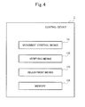
- control means 2 of the library device 100 is configured including a movement control means 101. a verifying means 102 and an adjustment means 103.
- the movement control means 101 moves the medium transfer means 5.
- the verifying means 102 verifies the movement distance of the medium transfer means 5 by comparing: an actual encoder count number counted by an encoder sensor S3 shown in Fig. 3 according to a movement of the medium transfer means 5 when the stepping motor 51 shown in Fig. 3 is driven by the number of pulses according to the movement distance of the medium transfer means 5: and an assumed encoder count number assumed based on the number of pulses according to the movement distance of the medium transfer means 5.
- the adjustment means 103 determines a proof factor to be used when the assumed encoder count number assumed based on the number of pulses according to the movement distance of the medium transfer means 5 is calculated.
- the library device 100 according to the present exemplary embodiment will be described in detail with reference to the accompanying drawing.
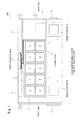
- Fig. 1 is a diagram (top view), viewing the library device 100 from the top
- Fig. 2 is a diagram (side view), viewing the library device 100 from a side and the rear
- Fig. 2 (a) is a diagram when seeing the library device 100 from a first side face shown in Fig. 1
- Fig. 2 (b) is a diagram when seeing the library device 100 from a second side face shown in Fig. 1
- Fig. 2 (c) is a diagram when seeing the library device 100 from the rear side shown in Fig. 1 .
- illustration of the accessor mechanism 5 is omitted.
- the library device 100 is configured including the drive device 1, a control device 2, a power supply device 3, a backboard 4, the accessor mechanism 5, the magazine 6, the medium 7, a LAN connector 8 and an operation panel 9.
- the magazine 6 is an example of a medium storing means for accommodating the medium 7.
- the magazine 6 according to the present exemplary embodiment has plural cells (parts separated by a dashed line) 11 and adopts the deep cell design method capable of accommodating two media 7 for each one cell 11.
- the magazine 6 according to the present exemplary embodiment has three tiers of deep cells in the height direction (Y-direction) of the library device 100. and has five lines of deep cells in the depth direction (X-direction) of the library device 100.
- the magazine 6 has a structure capable of being removed from the front side (front face side) of the library device 100.
- the medium 7 is a computer-readable medium, such as, for example, a cartridge packing a magnetic tape.
- the accessor mechanism is an example of medium transfer means for transferring the medium 7.
- the accessor mechanism 5 according to the present exemplary embodiment can move from the rear side of the library device 100 to the front side as shown in Fig. 1 , or move from the front side to the rear side of the library device 100 (X-direction of Fig. 1 and Fig. 2 (b)).
- the accessor mechanism 5 can move from the bottom base side to the upper surface side of the library device 100, or move from the upper surface side to the bottom base side of the library device 100 (Y-direction of Fig. 2 (b) ).
- the library device 100 is configured such that a stepping motor is used as a motor which is used for moving the accessor mechanism 5 in X-direction of Fig. 1 and Fig. 2 (b), a DC motor is used as a motor which is used for moving it in Y-direction of Fig. 2 (b) , and thus the movement of the accessor mechanism 5 is controlled using separate motors.
- a stepping motor is used as a motor which is used for moving the accessor mechanism 5 in X-direction of Fig. 1 and Fig. 2 (b)
- a DC motor is used as a motor which is used for moving it in Y-direction of Fig. 2 (b) , and thus the movement of the accessor mechanism 5 is controlled using separate motors.
- the accessor mechanism 5 when there is an instruction to read from or write into a predetermined medium 7, for example, the accessor mechanism 5 performs transferring the medium 7. Specifically, according to the instruction from the control device 2, the accessor mechanism 5 pulls the medium 7 designated by the control device 2 out from the magazine 6, transfers the pulled medium 7 to the drive device 1, and insert it in a slot 10. Then, when reading from or writing into the medium 7 ends, the accessor mechanism 5 pull the medium 7 out from the slot 10 of the drive device 1, transfers the pulled medium 7 to the originally stored magazine 6, and put the medium 7 in the originally stored cell 11.
- the drive device 1 is an example of a medium reading and writing means which reads information stored in the medium 7 and writes information in the medium 7.
- the drive device 1 according to the present exemplary embodiment reads data from the medium 7 put in the slot 10 or writes data in the medium 7.
- two drive devices 1 are arranged in a manner being stacked up and down in the height direction of the library device 100 (Y-direction of Fig. 2(b) and (c)).
- the control device 2 is an example of the control means which controls the library device 100.
- the control device 2 When instructions for reading or writing a medium 7 are accepted from a host or the like which is not illustrated, the control device 2 according to the present exemplary embodiment performs control such that the medium 7 stored in the magazine 6 is conveyed into the drive device 1 using the accessor mechanism 5. and the reading or writing processing for the medium 7 is performed by the drive device 1. and the medium 7 stored again in the magazine 6.
- the power supply device 3 is an example of a power supply means which supplies electricity for making the library device 100 operate.
- the backboard 4 is an example of a connecting means which connects each equipment (device) in the library device 100 electrically.
- the backboard 4 according to the present exemplary embodiment is configured so that each of the drive device 1, the control device 2 and the power supply device 3 can be connected to the backboard 4.
- the LAN connector 8 and the operation panel 9 are configured so that they can be connected to the backboard 4 via a cable.
- the accessor mechanism 5 is configured such that it can be connected to the front panel via a cable and relayed by the front panel to be connected to the backboard 4 finally.
- the LAN connector 8 is a connector for connecting the library device 100 to a local area network.
- the operation panel 9 accepts various kinds of operation and indicates various kinds of information.
- the library device 100 is configured so that the control device 2 and the power supply device 3 may be arranged along the first side face, Also, it is configured so that the backboard 4 may be arranged between the control device 2 and the power supply device 3. Meanwhile, it is configured so that the backboard 4 may be arranged in an atmost midsection in the depth direction (X-direction) of the library device 100.
- the library device 100 is configured so that the magazine 6 may be attached next to the control device 2, the backboard 4 and the power supply device 3 arranged along the first side face, and, in addition, the drive device 1 may be arranged next to the power supply device 3. That is, the drive device 1 is configured so that the doorway (insertion and removal gate) for the medium 7 in the slot 10 may face in the direction toward the second side face.
- the library device 100 is configured so that the doorway (insertion and removal gate) for the medium 7 in each deep cell of the magazine 6 may face in the direction toward the second side face. Further, it is configured so that the doorway for the medium 7 in the slot 10 and the doorway for the medium 7 in each deep cell may be in parallel with each other.
- the library device 100 is configured so that the accessor mechanism may be arranged in the second side face. Also, it is configured so that a space which is a movable range of the accessor mechanism 5 (movable scope in X-direction of the library device 100) may be provided along the second side face.
- the library device 100 is configured so that it may have only one backboard 4, and the control device 2, the power supply device 3 and the drive device 1 may be connected to the blackboard 4 directly. That is, it is configured so that one backboard 4 may be shared by three devices 2, 3 and 1.
- the three devices 2, 3 and 1 have a structure such that they can be attached to and detached from the backboard 4, and the control device 2 has a structure such that it can be attached to and detached from the backboard 4 from the front side of the library device 100, For example, as shown in Fig. 1 , the control device 2 is configure so that it can be pulled out toward the front side (direction of the arrow in Fig. 1 ).
- the power supply device 3 and the drive device 1 have structures such that they can be attached to and detached from the blackboard 4 from the rear side of the library device 100. For example, as shown in Fig. 1 , the power supply device 3 and the drive device 1 are configured so that they may be pulled out toward the rear side (direction of the arrow in Fig. 1 ).
- Fig. 3 is a diagram showing an exemplary schematic configuration inside the accessor mechanism 5, and it indicates an exemplary driving configuration when moving the accessor mechanism 5 in X-direction as shown in Fig. 1 .
- Fig. 3 (a) indicates an exemplary schematic configuration inside the accessor mechanism 5
- Fig. 3(b) indicates an expanded exemplary configuration of the part including the stepping motor 51 and a plurality of gears 52 in Fig. 3 (a) .
- the accessor mechanism 5 has the stepping motor 51 and the plurality of gears 52, and the plurality of gears 52 rotate along with rotation of the stepping motor 51, and the accessor mechanism 5 will move in X-direction shown in Fig. 1 and Figs. 3 (a) and (b).
- the encoder sensor 53 is installed in a certain gear 521 among gears of which the accessor mechanism 5 is configured, and the control device 2 will acquire the encoder count number counted by the encoder sensor 53.
- the encoder sensor 53 is a publicly known encoder sensor, and is configured having a light-emitting part which emits light and a light accepting part which receives light.
- light emitted by the light-emitting part passes through a slit provided in the certain gear 521, and, by the light accepting part receiving light which has passed through the slit, the encoder sensor 53 generates output signals of High and Low, and the encoder count number will be counted based on the output signal.
- two encoder sensors 53 are provided in the certain gear 521, the control device 2 acquires encoder count numbers counted by the two encoder sensors 53, and the control device 2 shifts the phases of the two encoder sensors 53 and acquires a highly accurate encoder count number.
- Fig. 3 (b) it has been arranged such that two encoder sensors 53 are provided in the certain gear 521, the control device 2 acquires the encoder count numbers counted by the two sensors 53, and the control device 2 acquires a highly accurate encoder count number using encoder count numbers acquired from the two sensors 53.
- a configuration, in which one encoder sensor 53 is provided in the certain gear 521, and the control device 2 acquires the encoder count number counted by that one encoder sensor 53 is also possible.
- the control device 2 is configured including the movement control means 101, the verifying means 102, the adjustment means 103 and a memory 104.
- the movement control means 101, the verifying means 102 and the adjustment means 103 can be realized by one piece of firmware.
- the movement control means 101 controls movement of the accessor mechanism 5. By driving the stepping motor 51 shown in Fig. 3 by the number of pulses according to the movement distance of the accessor mechanism 5. the movement control means 101 moves the accessor mechanism 5.
- the verifying means 102 verifies the movement distance of the accessor mechanism 5.
- the verifying means 102 compares the encoder count number counted actually by the encoder sensor 53 shown in Fig. 3 according to the movement of the accessor mechanism 5 and the assumed encoder count number assumed based on the number of pulses according to the movement distance of the accessor mechanism 5 to verify the movement distance of the accessor mechanism 5.
- the adjustment means 103 determines the proof factor to be used when the encoder count number that is assumed based on the number of pulses according to the movement distance of the accessor mechanism 5 is calculated.
- the adjustment means 103 determines the above-mentioned proof factor when the library device 100 is powered on, for example.
- the verifying means 102 can calculate, based on the proof factor determined by the adjustment means 103, the encoder count number assumed based on the number of pulses according to the movement distance of the accessor mechanism 5, and verify the movement distance of the accessor mechanism 5 by comparing the assumed encoder count number that has been calculate and the encoder count number counted actually by the encoder sensor 53 shown in Fig. 3 according to the movement of the accessor mechanism 5.
- determination of the proof factor performed by the adjustment means 103 is not limited to the timing when the library device 100 is powered on, and it can be performed at an arbitrary timing.
- the memory 104 manages various kinds of information used by the control device 2.
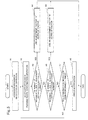
- Fig. 5 indicates an example of processing operations when the library device 100 is powered on
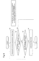
- Fig. 6 indicates an example of processing operations at the time of the designated position verification operation for the accessor mechanism 5.
- the designated position verification operation is performed at the time of the normal operation for the library device 100.
- Step A1 When the power of the library device 100 is turned on, the control device 2 performs the initialization operation of the accessor mechanism 5 (Step A1). Because the initialization operation is a publicly known operation, description of the processing in detail is omitted. On this occasion, the control device 2 initializes the encoder count number counted by the encoder sensor 53, and sets the encoder count number to 0.
- the movement control means 101 performs a running route confirmation operation of the accessor mechanism 5, and confirms whether or not there is an obstacle in a running route of the accessor mechanism 5 (Step A2).
- the running route confirmation operation moves the accessor mechanism 5 from the position of the home position (position of A shown in Fig. 1 ) to the final position of the farthest medium 7 (position of B shown in Fig. 1 ), and confirms whether or not there is an obstacle in the running route from the position A that is the home position to the final position B.
- the movement control means 101 will perform the running route confirmation operation by driving the stepping motor 51 by the number of movement pulses being managed in the memory 104 to move the accessor mechanism 5 from the position A of the home position to the final position B.
- the adjustment means 103 acquires the encoder count number counted by the encoder sensor 53 until the time when the stepping motor 51 has been driven by the number of movement pulses, and determines the adjustment factor used as the proof factor based on the number of movement pulses and the encoder count number (Steps A3-A6).
- the proof factor is a factor used when the verifying means 102 calculates the above-mentioned assumed encoder count number in the processing of the designated position verification operation mentioned later.
- the control device 2 keeps a plurality of adjustment factors (adjustment factor A and adjustment factor B) used as the proof factor in the memory 104 under management in advance (in this regard, however, the adjustment factor A is different from the adjustment factor B), and the adjustment means 103 determines, based on the number of movement pulses, the encoder count number and the plurality of adjustment factors managed in the memory 104 (adjustment factor A and adjustment factor B), an adjustment factor used as the proof factor (Steps A3-A6).
- the adjustment means 103 determines whether or not the relation between the number of movement Pulses, the encoder count number and the adjustment factor A satisfies the following formula 1 or not (Step A3).
- step A3/Yes the adjustment means 103 determines to use the adjustment factor A as the proof factor (Step A4), and ends processing (End).
- step A3/No determines whether the relation between the number of movement pulses, the encoder count number and the adjustment factor B satisfies the following formula 2 (step A5).
- the adjustment means 103 determines to use the adjustment factor B as a proof factor (Step A6), and ends processing (End).
- the adjustment means 103 determines whether or not the movement control means 101 has performed the running route confirmation operation N (N is an arbitrary integer) times (Step A7) and, when having not performed the running route confirmation operation N times (step A7/No), the movement control means 101 performs the running route confirmation operation again (Step A2), the adjustment means 103 acquires the encoder count number which has been counted by the encoder sensor 53 until the time when the stepping motor 51 has been driven by the number of movement pulses, and, based on the number of movement pulses and the encoder count number, determines the adjustment factor used as the proof factor (Steps A3-A6).
- the adjustment means 103 performs the error notification (Step A8) and ends processing (End).
- the error notification processing such as notifying a user to the effect that the proof factor cannot be determined will be performed.
- the accessor mechanism 5 for which the adjustment factor A of Formula I is 0.8 and the adjustment factor B of Formula 2 is 0.9. Also, it is supposed that the number of movement pulses required for moving the accessor mechanism 5 from the position of the home position (position of A shown in Fig. 1 ) to the final position of the farthest medium 7 (position of B shown in Fig. 1 ) is 1000 pulses.
- the adjustment means 103 acquires the encoder count number counted by the encoder sensor 53 until the time when the stepping motor 51 is driven taking the number of movement pulses as 1000 pulses, and it is supposed that the encoder count number which has been acquired is 900.
- the adjustment means 103 can determine the adjustment factor used as the proof factor based on the relation between a count number that has been counted by the encoder sensor 53 until the time when the stepping motor 51 is driven by the number of movement pulses and that number of the movement pulses.
- the adjustment factor used as the proof factor is determined using the number of movement pulses required for moving the accessor mechanism 5 from the position A of the home position to the final position B.
- the number of pulses which is used when the adjustment factor used as the proof factor is determined is not limited to the number of movement pulses mentioned above, and it is possible to determine the adjustment factor used as the proof factor using the predetermined number of pulses required for moving the accessor mechanism 5 from the position A of the home position to a predetermined position.
- the encoder count number which is counted by the encoder sensor 53 until the time when the stepping motor 51 is driven by the predetermined number of pulses required for moving the accessor mechanism 5 from the position A of the home position to a predetermined position, is acquired, and the adjustment factor used as the proof factor is determined based on the above predetermined number of pulses and the encoder count number.
- the movement control means 101 when instructions to move the accessor mechanism 5 are accepted during the normal operation, the movement control means 101 performs the designated position movement operation to move the accessor mechanism 5 to the designated position (position of a cell 11 designated from the user) accepted by the movement instructions (Step B1).
- the movement control means 101 will perform the designated position movement operation by driving the stepping motor 51 by the number of pulses required for moving it from the position A of the home position to the designated position, to move the accessor mechanism 5 from the position A of the home position to the designated position.
- the verifying means 102 acquires the encoder count number which has been counted by the encoder sensor 53 until the time when the stepping motor 51 has been driven by the number of pulses required for moving it to the designated position, performs, based on the number of pulses required for moving the accessor mechanism 5 to the designated position and the encoder count number, designated position verification of the accessor mechanism 5 using the following Formula 3, and confirms whether there is a correlation between the number of pulses required for moving it to the designated position and the encoder count number (Step B2).
- a proof factor X of the following Formula 3 uses the adjustment factor which the adjustment means 103 has determined as the proof factor by the processing of Fig. 5 (in the specific example mentioned above, the adjustment factor B).
- proof factor X encoder count number
- step B2/Yes) the verifying means 102 judges that there is a correction between the number of pulses required for moving the accessor mechanism 5 to the designated position and the encoder count number, determines that it has moved to the designated position, and ends processing (End).
- the encoder count number obtained by the number of pulses required for moving to the designated position * proof factor X indicated by the above-mentioned Formula 3 will be an assumed encoder count number
- the encoder count number counted by the encoder sensor 53 will be identical to the assumed encoder count number.
- the verifying means 102 can judge that there is a correction between the number of pulses required for moving to the designated position and the encoder count number, and determine that the accessor mechanism has been moved to the designated position.
- step B2/No the verifying means 102 judges that there are no correlations between the number of pulses required for moving to the designated position and the encoder count number, and determines that the accessor mechanism 5 has not moved to the designated position.
- the verifying means 102 judges that there are no correlations between the number of pulses required for moving to the designated position and the encoder count number, and can determine that the accessor mechanism 5 has not moved to the designated position.
- the verifying means 102 judges whether the movement control means 101 has performed the designated position movement operation N times (N is an arbitrary integer) (Step B3), and, when having not performed N times (step B3/No), the movement control means 101 performs the designated position movement operation again (Step B1) and the verifying means 102 acquires the encoder count number which has been counted by the encoder sensor 53 until the time when the stepping motor 51 has been driven by the number of pulses required for moving to the designated position, and confirms whether there is a correlation between the number of pulses acquired and the encoder count number (Step B2).
- the verifying means 102 performs the error notification (Step B4) and ends processing (End).
- the error notification processing for notifying the user that the accessor mechanism 5 cannot be moved to the designated position will be performed.
- the control device 2 of the library device 100 manages the plurality of adjustment factors (the adjustment factor A and the adjustment factor B; in this regard, however, the adjustment factor A is different from the adjustment factor B) in the memory 104 in advance. Then, the movement control means 101 drives the stepping motor 51 by the number of movement pulses set in advance and performs the running route confirmation operation, and, at the same time, the adjustment means 103 acquires the encoder count number which has been counted by the encoder sensor 53 until when the stepping motor 51 is driven by the number of movement pulses.
- the verifying means 102 can verify the movement distance of the accessor mechanism 5 by the encoder count number that has been counted by the encoder sensor 53.
- the movement control means 101. the verifying means 102 and the adjustment means 103 can be realized by one piece of firmware, the movement control of the accessor mechanism 5 can be realized by the one piece of firmware. Further, the library device 100 according to the present exemplary embodiment can adjust the relation between the number of pulses required for moving to the designated position and the encoder count number without changing the hardware configuration.
- the exemplary embodiment mentioned above is a preferred exemplary embodiment of the present invention, and the scope of the present invention is not limited only to the above-mentioned exemplary embodiment, and the present invention can be carried out in a form in which various changes are made within a range that does not deviate from the point of the present invention.
- control device 2 has been described about the movement control in X-direction of the accessor mechanism 5 shown in Fig. 1 .
- the stepping motor is also used for movement control in Y-direction of the accessor mechanism at shown in Fig. 2 , the same control as the movement control of X-direction can be performed.
- the adjustment means 103 is arranged such that it performs the processing operations shown in Fig. 5 at the time of the power-ON of the library device 100 and determines the adjustment factor used as the proof factor, and the verifying means 102 performs the designated position verification operation shown in Fig. 6 using the proof factor determined by the adjustment means 103.
- the timing when the adjustment factor used as the proof factor is determined is not limited to the timing when the library device 100 is power-ON, and it can be performed at an arbitrary timing.
- it can be arranged such that, when determination start instructions for the adjustment factor used as the proof factor is accepted from the operation panel 9 or the like, the adjustment means 103 performs the processing operations shown in Fig. 5 .
- the adjustment means 103 performs the processing operations shown in Fig. 5 automatically. That is, the adjustment means 103 can adjust the proof factor before the verifying means 102 uses it, or can adjust the proof factor after the verifying means 102 has used it.
- control operation in each device constituting the library device 100 in the present exemplary embodiment mentioned above can be carried out using hardware or software or a combined structure of the both.
- the program can be recorded in a hard disk and ROM (Read Only Memory) as a recording medium in advance.
- the program can be stored (record) in a removable recording medium temporarily or permanency.
- Such removable recording medium is possible to be provided as so-called packaged software.
- a floppy (registered trademark) disk as the removable recording medium.
- CD-ROM Compact Disc Read Only Memory
- MO Magnetic optical
- DVD Digital Versatile Disc
- a magnetic disk and a semiconductor memory are cited.
- the program will be installed in the computer from the removable recording medium mentioned above. Or, it will be wirelessly transmitted to the computer from a download site. Or, it will be transmitted to the computer by a wire via a network.
- the library device 100 in the present exemplary embodiment can be constructed not only such that it is carried out in a time series manner according to the processing operations described in the above-mentioned exemplary embodiment, but also such that it is carried out in parallel or separately according to the processing capability of a device carrying out the processing or as necessary.
Landscapes
- Automatic Tape Cassette Changers (AREA)
- Automatic Disk Changers (AREA)
Abstract
Description
- The present invention rotates to a library device.
- As a general library device, there is an instance having a configuration disclosed in patent document 1 (Japanese Patent Application Laid-Open No.
2008-217938 - As shown in
Fig. 7 , alibrary device 1 ofpatent document 1 is configured including: a medium storing means (cartridge magazine 5) having acell 4 which individually stores a plurality of media (data cartridge 2) storing various kinds of information: a medium reading and writing means (drive device 3) that loads thedata cartridge 2, to read and write information: and a medium transfer means (accessor mechanism 6) for accessing apredetermined cell 4, to put in or take out thedata cartridge 2, or putting in or taking out a data cartridge into/from the predetermineddrive device 3, and the like. - Furthermore, there is an instance, which controls a move of the
accessor mechanism 6, as shown inFig. 7 (a move in X-direction or Y-direction shown inFig. 7 ) using a stepping motor. - When the move of the
accessor mechanism 6 as shown inFig. 7 (in X-direction shown inFig. 7 , for example) is controlled using the stepping motor, theaccessor mechanism 6 will move by a distance according to a number of pulses of the stepping motor (a movement distance of theaccessor mechanism 6 = the number of pulses of the stepping motor * a movement distance that theaccessor mechanism 6 can move by one pulse). For this reason, as shown inFig. 8 , when theaccessor mechanism 6 is desired to be moved to a specific designated position (the position of B inFig. 8 ) from the home position (the position of A inFig. 8 ), for example, it is possible to move theaccessor mechanism 6 from the home position A to the designated position B by driving the stepping motor by the number of pulses according to the movement distance from the home position A to the designated position B.Fig. 8 shows an example of moving theaccessor mechanism 6 shown inFig. 7 in X-direction using the stepping motor. - However, when a step-out or the like occurs to the stepping motor, although the
accessor mechanism 6 does not move, only the number of pulses of the stepping motor is counted. For this reason, when the step-out or the like occurs to the stepping motor, the number of pulses of the stepping motor and the movement distance of theaccessor mechanism 6 do not synchronize, and thus, even if the stepping motor are driven by the number of pulses according to the movement distance from the home position A to the designated position B, theaccessor mechanism 6 could not be moved from the home position A to the designated position B. - For this reason, there is an instance, in which the
accessor mechanism 6 is moved using the stepping motor and the movement distance of theaccessor mechanism 6 can be verified with an encoder count number counted by an encoder sensor. In this case, the number of pulses of the stepping motor and the encoder count number counted by the encoder sensor will be made to have a correlation. Specifically, it is made such that the encoder count number counted by the encoder sensor when the stepping motor is driven by the predetermined number of pulses (an actual encoder count number) will be an assumed encoder count number obtained by multiplying the predetermined number of pulses by a proof factor (the predetermined number of pulses * the proof factor). That is, it is made such that the assumed encoder count number (the predetermined number of pulses * the proof factor) = the actual encoder count number. - In this case, when the
accessor mechanism 6 is desired to be moved from the home position A to the designated position B, the stepping motor is driven by the number of pulses according to the movement distance from the home position A to the designated position B, and, at the same time, the encoder count number which has been counted by the encoder sensor until the stepping motor is driven by that number of` pulses is cheeked. Then, it is confirmed whether or not there is a correlation between the number of pulses of the stepping motor and the encoder count number (whether they satisfy a relation that the number of pulses of the stepping motor * proof factor = actual encoder count number), and, when there is a correlation between the number of pulses of the stepping motor and the encoder count number (when they satisfy the relation that the number of pulses of a stepping motor * proof factor = actual encoder count number), it is determined that theaccessor mechanism 6 has moved to the designated position B. When there is no correlation between the number of pulses of the stepping motor and an encoder count number (when they do not satisfy the relation that the number of pulses of the stepping motor * proof factor = actual encoder count number), it is determined that theaccessor mechanism 6 has not moved to the designated position B. As a result, it is possible to move theaccessor mechanism 6 using the stepping motor, and check the movement distance of theaccessor mechanism 6 by the encoder count number counted by the encoder sensor. - However, there is a case where, by any extrinsic factors, the relation between the number of pulses of the stepping motor and the encoder count number (the relation that the number of pulses of the stepping motor * proof factor = actual encoder count number) is changed, and, as a result, it becomes impossible to check the movement distance of the
accessor mechanism 6 any more by the encoder count number counted by the encoder sensor. As the extrinsic factor, a case where the module of gears, of which theaccessor mechanism 6 is composed, has been changed or the like is mentioned. - For this reason, development for a mechanism, which can confirm the movement distance of the
accessor mechanism 6 by the encoder count number counted by the encoder sensor even if the relation between the number of pulses of the stepping motor and the encoder count number (the relation that the number of pulses of a stepping motor * proof factor =actual encoder count number) is changed, is needed. - Meanwhile, as a technical document filed prior to the present invention, there is a literature which discloses a technology which can perform, when there is a change in a structure of a library device, processing to update location information on all frames easily in a short time by limiting such cases (for example, refer to patent document 2).
- In the above-mentioned
patent document 2, in a case where an accessor or an accessor component of library device is replaced, by the accessor before the replacement, position control information for a standard unit is measured in advance and is made to be first position control information, and, in addition, position control information for each frame is measured in advance and is made to be second position control information. Next, position control information for the standard unit is measured by the accessor after the replacement and is made be third position control information. Then, a difference value between the first position control information and the third position control information is obtained, then the second position control information is corrected by the difference value and is made to be fourth position control information. Then, the operation of the accessor after the replacement will be controlled based on the fourth position control information. -
- [Patent Literature 1] Japanese Patent Application Laid-Open No.
2008-217938 - [Patent Literature 2] Japanese Patent Application Laid-Open No.
1999-149696 - It is disclosed, in the above-mentioned
patent literature 2, retarding a point of updating position control information on each frame and each cell of a library device after a replacement and controlling, operations of an accessor after the replacement. - However, there is neither description nor suggestion at all in the above-mentioned
patent literature 2 about a mechanism for verifying the movement distance of the accessor mechanism, which is a medium transfer means, by the encoder count number counted by the encoder sensor even if the relation between the number of pulses of the stepping motor and the encoder count number (the relation that the number of pulses of a stepping motor * proof factor = actual encoder count number) changes. - The present invention has been made in view of the above-mentioned circumstances, and the object is to provide a library device, a control method and a program which can verify a movement distance of a medium transfer means by an encoder count number counted by an encoder sensor even if the relation between a number of pulses of a stepping motor and an encoder count number (the relation that the number of pulses of a stepping motor * proof factor = actual encoder count number) changes.
- In order to achieve the above object, the present invention has the following feature.
- A library device according to the present invention, comprises: a medium storing means for accommodating a plurality of computer-readable media: a medium reading and writing means for performing at least one of reading information stored in said medium and writing information in said medium: a medium transfer means for transferring said medium between said medium storing means and said medium reading and writing means: and a control means for controlling said medium transfer means, wherein said control means incudes: a movement control means for moving said medium transfer means by driving a stepping motor by a number of pulses according to a movement distance of said medium transfer means: a verifying means for comparing an actual encoder count number counted, upon said stepping motor having been driven by said number of pulses, by an encoder sensor according to a movement of said medium transfer means, and an assumed encoder count number assumed based on said number of pulses: and an adjustment means for determining a proof factor used at a time of calculating the assumed encoder count number assumed based on said number of pulses.
- A library device according to the present invention comprises: a medium storing means for accommodating a plurality of computer-readable media: a medium reading and writing means for performing at least one of reading information stored in said medium and writing information in said medium: a medium transfer means for transferring said medium between said medium storing means and said medium reading and writing means: and a control means for moving said medium transfer means by driving a stepping motor by a number of pulses according to a movement distance of said medium transfer means, wherein said control means includes: an adjustment means for determining, upon accepting an adjustment instruction, a proof factor used at a time of calculating an assumed encoder count number assumed based on the number of pulses according to the movement distance of said medium transfer means: and a verifying means for comparing, upon verifying said movement distance of said medium transfer means, the assumed encoder count number assumed based on said proof factor determined by said adjustment means and the number of pulses according to the movement distance of said medium transfer means, and an actual encoder count number counted, upon said stepping motor having been driven by the number of pulses according to the movement distance of said medium transfer means, by an encoder sensor.
- A control method according to the present invention is a control method carried out In a library device, configured comprising a medium storing means for accommodating a plurality of computer-readable media, a medium reading and writing means for performing at least one of reading information stored in said medium and writing information in said medium, a medium transfer means for transferring said medium between said medium storing means and said medium reading and writing means, and a control means for controlling said medium transfer means, wherein said control means carrying out: a movement control step of moving said medium transfer means by driving a stepping motor by a number of pulses according to a movement distance of said medium transfer means: a verifying step of comparing an actual encoder count number counted, upon said stepping motor having been driven by said number of pulses, according to a movement of said medium transfer means, and an assumed encoder count number assumed based on said number of pulses: and an adjusting step of determining a proof factor used at a time of calculating the assumed encoder count number assumed based on said number of pulses.
- A program according to the present invention is a program to be executed by a library device, configured comprising a medium storing means for accommodating a plurality of computer-readable media, a medium reading and writing means for performing at least one of reading information stored in said medium and writing information in said medium, a medium transfer means for transferring said medium between said medium storing means and said medium reading and writing means, and a control means for controlling said medium transfer means, said program causing said control means to execute; movement control processing for moving said medium transfer means by driving a stepping motor by a number of pulses according to a movement distance of said medium transfer means: a verifying processing for comparing an factual encoder count number counted, upon said stepping motor having been driven by said number of pulses, according to a movement of said medium transfer means, and an assumed encoder count number assumed based on said number of pulses: and an adjusting processing for determining a proof factor used at a time of calculating the assumed encoder count number assumed based on said number of pulses.
- According to the present invention, even if the relation between the number of pulses of the stepping motor and the encoder count number (the relation that the number of pulses of a stepping motor * proof factor = actual encoder count number) changes, the movement distance of the medium transfer means can be verified by the encoder count number counted by the encoder sensor.
-
-
Fig. 1 is a top view showing an exemplary configuration of alibrary device 100 according to the present exemplary embodiment. -
Fig. 2 is a side view and a rear view showing the exemplary configuration of thelibrary device 100 according to the present exemplary embodiment. -
Fig. 3 is a diagram showing a schematic exemplary configuration of theaccessor mechanism 5. -
Fig. 4 is a diagram showing an exemplary configuration of thecontrol apparatus 2 according to the present exemplary embodiment. -
Fig. 5 is a diagram showing a processing example of operations on power-ON of thelibrary device 100 according to the present exemplary embodiment. -
Fig. 6 is a diagram showing a processing example of operations at the time of a designated position confirmation operation for theaccessor mechanism 5. -
Fig. 7 is a diagram showing an exemplary configuration of a library device related to the present invention. -
Fig. 8 is a diagram showing an example of controlling the movement of theaccessor mechanism 6 shown inFig. 7 using the stepping motor. - First, the outline of the
library device 100 according to the present exemplary embodiment will be described with reference toFig. 1 ,Fig. 3 andFig. 4 . - As shown in
Fig. 1 , thelibrary device 100 according to the present exemplary embodiment is configured including; a medium storing means (corresponding to a magazine 6) which can accommodate plural computer readable medium 7: a medium reading and writing means (corresponding to a drive device 1) which performs at least one of reading information stored in themedium 7 and writing information to the medium 7: a medium transfer means (corresponding to an accessor mechanism 5) which transfers themedium 7 between the medium storing means 6 and the medium reading and writing means 1: and a control means (corresponding to a control device 2) which controls the medium transfer means 5. - As shown in
Fig. 4 . the control means 2 of thelibrary device 100 according to the present exemplary embodiment is configured including a movement control means 101. a verifyingmeans 102 and an adjustment means 103. - By driving a stepping
motor 51 shown inFig. 3 by the number of pulses according to a movement distance of the medium transfer means 5, the movement control means 101 moves the medium transfer means 5. - The verifying
means 102 verifies the movement distance of the medium transfer means 5 by comparing: an actual encoder count number counted by an encoder sensor S3 shown inFig. 3 according to a movement of the medium transfer means 5 when thestepping motor 51 shown inFig. 3 is driven by the number of pulses according to the movement distance of the medium transfer means 5: and an assumed encoder count number assumed based on the number of pulses according to the movement distance of the medium transfer means 5. - The adjustment means 103 determines a proof factor to be used when the assumed encoder count number assumed based on the number of pulses according to the movement distance of the
medium transfer means 5 is calculated. - In the control means 2 of the
library device 100 according to the present exemplary embodiment, the adjustment means 103 will determine a proof factor used on calculating an assumed encoder count number, assumed based on the number of pulses according to the movement distance of the medium transfer means 5. For this reason, because, even if the relation between the number of pulses of thestepping motor 51 and the encoder count number (the relation that the number of pulses of thestepping motor 51 * proof factor = actual encoder count number) changes, the assumed encoder count number assumed based on the number of pulses according to the movement distance of the medium transfer means 5 can be calculated, then the verifyingmeans 102 can verify the movement distance of the medium transfer means 5 by the encoder count number counted by theencoder sensor 53 based on the proof factor determined by the adjustment means 103. Hereinafter, thelibrary device 100 according to the present exemplary embodiment will be described in detail with reference to the accompanying drawing. - First, an exemplary configuration of the
library device 100 according to the present exemplary embodiment will be described with reference toFig. 1 andFig. 2 .Fig. 1 is a diagram (top view), viewing thelibrary device 100 from the top, andFig. 2 is a diagram (side view), viewing thelibrary device 100 from a side and the rear, and Fig. 2 (a) is a diagram when seeing thelibrary device 100 from a first side face shown inFig. 1 , and Fig. 2 (b) is a diagram when seeing thelibrary device 100 from a second side face shown inFig. 1 . and Fig. 2 (c) is a diagram when seeing thelibrary device 100 from the rear side shown inFig. 1 . Meanwhile, inFig. 2 (b) , illustration of theaccessor mechanism 5 is omitted. - The
library device 100 according to the present exemplary embodiment is configured including thedrive device 1, acontrol device 2, apower supply device 3, abackboard 4, theaccessor mechanism 5, themagazine 6, themedium 7, aLAN connector 8 and an operation panel 9. - The
magazine 6 is an example of a medium storing means for accommodating the medium 7. Themagazine 6 according to the present exemplary embodiment has plural cells (parts separated by a dashed line) 11 and adopts the deep cell design method capable of accommodating twomedia 7 for each onecell 11. As shown inFig. 2 (b) , themagazine 6 according to the present exemplary embodiment has three tiers of deep cells in the height direction (Y-direction) of thelibrary device 100. and has five lines of deep cells in the depth direction (X-direction) of thelibrary device 100. As shown inFig. 1 , themagazine 6 has a structure capable of being removed from the front side (front face side) of thelibrary device 100. - The
medium 7 is a computer-readable medium, such as, for example, a cartridge packing a magnetic tape. - the accessor mechanism is an example of medium transfer means for transferring the
medium 7. Theaccessor mechanism 5 according to the present exemplary embodiment can move from the rear side of thelibrary device 100 to the front side as shown inFig. 1 , or move from the front side to the rear side of the library device 100 (X-direction ofFig. 1 and Fig. 2 (b)). - As shown in
Fig. 2 (b) , theaccessor mechanism 5 can move from the bottom base side to the upper surface side of thelibrary device 100, or move from the upper surface side to the bottom base side of the library device 100 (Y-direction ofFig. 2 (b) ). - Meanwhile, the
library device 100 according to the present exemplary embodiment is configured such that a stepping motor is used as a motor which is used for moving theaccessor mechanism 5 in X-direction ofFig. 1 and Fig. 2 (b), a DC motor is used as a motor which is used for moving it in Y-direction ofFig. 2 (b) , and thus the movement of theaccessor mechanism 5 is controlled using separate motors. - Also, when there is an instruction to read from or write into a
predetermined medium 7, for example, theaccessor mechanism 5 performs transferring themedium 7. Specifically, according to the instruction from thecontrol device 2, theaccessor mechanism 5 pulls the medium 7 designated by thecontrol device 2 out from themagazine 6, transfers the pulled medium 7 to thedrive device 1, and insert it in aslot 10. Then, when reading from or writing into the medium 7 ends, theaccessor mechanism 5 pull the medium 7 out from theslot 10 of thedrive device 1, transfers the pulled medium 7 to the originally storedmagazine 6, and put the medium 7 in the originally storedcell 11. - Meanwhile, in the deep cell method, when the designated
medium 7 is stored in the back side (first side face ofFig. 1 ) of thecell 11, evacuation operation which makes the medium 7 stored in the front side of the cell 11 (second side face ofFig. 1 ) be evacuated into an idle cell temporarily is needed, and thus theaccessor mechanism 5 will also perform the evacuation operation. - The
drive device 1 is an example of a medium reading and writing means which reads information stored in themedium 7 and writes information in themedium 7. Thedrive device 1 according to the present exemplary embodiment reads data from the medium 7 put in theslot 10 or writes data in themedium 7. In the present exemplary embodiment, as shown inFig. 2 (b) and Fig. 2(c) , twodrive devices 1 are arranged in a manner being stacked up and down in the height direction of the library device 100 (Y-direction of Fig. 2(b) and (c)). - The
control device 2 is an example of the control means which controls thelibrary device 100. When instructions for reading or writing a medium 7 are accepted from a host or the like which is not illustrated, thecontrol device 2 according to the present exemplary embodiment performs control such that the medium 7 stored in themagazine 6 is conveyed into thedrive device 1 using theaccessor mechanism 5. and the reading or writing processing for themedium 7 is performed by thedrive device 1. and the medium 7 stored again in themagazine 6. - The
power supply device 3 is an example of a power supply means which supplies electricity for making thelibrary device 100 operate. - The
backboard 4 is an example of a connecting means which connects each equipment (device) in thelibrary device 100 electrically. Thebackboard 4 according to the present exemplary embodiment is configured so that each of thedrive device 1, thecontrol device 2 and thepower supply device 3 can be connected to thebackboard 4. TheLAN connector 8 and the operation panel 9 are configured so that they can be connected to thebackboard 4 via a cable. Also, theaccessor mechanism 5 is configured such that it can be connected to the front panel via a cable and relayed by the front panel to be connected to thebackboard 4 finally. - The
LAN connector 8 is a connector for connecting thelibrary device 100 to a local area network. - The operation panel 9 accepts various kinds of operation and indicates various kinds of information.
- As shown in
Fig. 1 and Fig. 2 (a), thelibrary device 100 according to the present exemplary embodiment is configured so that thecontrol device 2 and thepower supply device 3 may be arranged along the first side face, Also, it is configured so that thebackboard 4 may be arranged between thecontrol device 2 and thepower supply device 3. Meanwhile, it is configured so that thebackboard 4 may be arranged in an atmost midsection in the depth direction (X-direction) of thelibrary device 100. - Also, as shown in
Fig. 1 , thelibrary device 100 according to the present exemplary embodiment is configured so that themagazine 6 may be attached next to thecontrol device 2, thebackboard 4 and thepower supply device 3 arranged along the first side face, and, in addition, thedrive device 1 may be arranged next to thepower supply device 3. That is, thedrive device 1 is configured so that the doorway (insertion and removal gate) for the medium 7 in theslot 10 may face in the direction toward the second side face. - As shown in
Fig. 1 , thelibrary device 100 according to the present exemplary embodiment is configured so that the doorway (insertion and removal gate) for the medium 7 in each deep cell of themagazine 6 may face in the direction toward the second side face. Further, it is configured so that the doorway for the medium 7 in theslot 10 and the doorway for the medium 7 in each deep cell may be in parallel with each other. - As shown in
Fig. 1 , thelibrary device 100 according to the present exemplary embodiment is configured so that the accessor mechanism may be arranged in the second side face. Also, it is configured so that a space which is a movable range of the accessor mechanism 5 (movable scope in X-direction of the library device 100) may be provided along the second side face. In thelibrary device 100 according to the present exemplary embodiment, the doorway for the medium 7 in theslot 10 and the doorway for the medium 7 in each deep cell face in the direction to this space, and theaccessor mechanism 5 inserts and removes the medium 7 from those doorways. - As shown in
Fig. 1 , thelibrary device 100 according to the present exemplary embodiment is configured so that it may have only onebackboard 4, and thecontrol device 2, thepower supply device 3 and thedrive device 1 may be connected to theblackboard 4 directly. That is, it is configured so that onebackboard 4 may be shared by threedevices - The three
devices backboard 4, and thecontrol device 2 has a structure such that it can be attached to and detached from thebackboard 4 from the front side of thelibrary device 100, For example, as shown inFig. 1 , thecontrol device 2 is configure so that it can be pulled out toward the front side (direction of the arrow inFig. 1 ). Thepower supply device 3 and thedrive device 1 have structures such that they can be attached to and detached from theblackboard 4 from the rear side of thelibrary device 100. For example, as shown inFig. 1 , thepower supply device 3 and thedrive device 1 are configured so that they may be pulled out toward the rear side (direction of the arrow inFig. 1 ). - Next, an exemplary schematic configuration of the inside of the
accessor mechanism 5 will be described with reference toFig. 3. Fig. 3 is a diagram showing an exemplary schematic configuration inside theaccessor mechanism 5, and it indicates an exemplary driving configuration when moving theaccessor mechanism 5 in X-direction as shown inFig. 1 .Fig. 3 (a) indicates an exemplary schematic configuration inside theaccessor mechanism 5, andFig. 3(b) indicates an expanded exemplary configuration of the part including the steppingmotor 51 and a plurality ofgears 52 inFig. 3 (a) . - As shown in
Figs. 3 (a) and (b) , theaccessor mechanism 5 has the steppingmotor 51 and the plurality ofgears 52, and the plurality ofgears 52 rotate along with rotation of the steppingmotor 51, and theaccessor mechanism 5 will move in X-direction shown inFig. 1 and Figs. 3 (a) and (b). As shown inFig. 3 (b) , theencoder sensor 53 is installed in acertain gear 521 among gears of which theaccessor mechanism 5 is configured, and thecontrol device 2 will acquire the encoder count number counted by theencoder sensor 53. - The
encoder sensor 53 according to the present exemplary embodiment is a publicly known encoder sensor, and is configured having a light-emitting part which emits light and a light accepting part which receives light. In theencoder sensor 53 according to the present exemplary embodiment, light emitted by the light-emitting part passes through a slit provided in thecertain gear 521, and, by the light accepting part receiving light which has passed through the slit, theencoder sensor 53 generates output signals of High and Low, and the encoder count number will be counted based on the output signal. In the present exemplary embodiment, as shown inFig. 3 (b) , twoencoder sensors 53 are provided in thecertain gear 521, thecontrol device 2 acquires encoder count numbers counted by the twoencoder sensors 53, and thecontrol device 2 shifts the phases of the twoencoder sensors 53 and acquires a highly accurate encoder count number. - Meanwhile, in
Fig. 3 (b) , it has been arranged such that twoencoder sensors 53 are provided in thecertain gear 521, thecontrol device 2 acquires the encoder count numbers counted by the twosensors 53, and thecontrol device 2 acquires a highly accurate encoder count number using encoder count numbers acquired from the twosensors 53. However, a configuration, in which oneencoder sensor 53 is provided in thecertain gear 521, and thecontrol device 2 acquires the encoder count number counted by that oneencoder sensor 53, is also possible. - Next, an exemplary inside configuration of the
control device 2 according to the present exemplary embodiment will be described with reference toFig. 4 . - The
control device 2 according to the present exemplary embodiment is configured including the movement control means 101, the verifying means 102, the adjustment means 103 and amemory 104. The movement control means 101, the verifying means 102 and the adjustment means 103 can be realized by one piece of firmware. - The movement control means 101 controls movement of the
accessor mechanism 5. By driving the steppingmotor 51 shown inFig. 3 by the number of pulses according to the movement distance of theaccessor mechanism 5. the movement control means 101 moves theaccessor mechanism 5. - The verifying means 102 verifies the movement distance of the
accessor mechanism 5. When the steppingmotor 51 shown inFig. 3 has been driven by the number of pulses according to the movement distance of theaccessor mechanism 5. the verifying means 102 compares the encoder count number counted actually by theencoder sensor 53 shown inFig. 3 according to the movement of theaccessor mechanism 5 and the assumed encoder count number assumed based on the number of pulses according to the movement distance of theaccessor mechanism 5 to verify the movement distance of theaccessor mechanism 5. The assumed encoder count number will be such that the number of pulses according to the movement distance of theaccessor mechanism 5 * proof factor= assumed encoder count number. - The adjustment means 103 determines the proof factor to be used when the encoder count number that is assumed based on the number of pulses according to the movement distance of the
accessor mechanism 5 is calculated. The adjustment means 103 determines the above-mentioned proof factor when thelibrary device 100 is powered on, for example. As a result, the verifying means 102 can calculate, based on the proof factor determined by the adjustment means 103, the encoder count number assumed based on the number of pulses according to the movement distance of theaccessor mechanism 5, and verify the movement distance of theaccessor mechanism 5 by comparing the assumed encoder count number that has been calculate and the encoder count number counted actually by theencoder sensor 53 shown inFig. 3 according to the movement of theaccessor mechanism 5. Meanwhile, determination of the proof factor performed by the adjustment means 103 is not limited to the timing when thelibrary device 100 is powered on, and it can be performed at an arbitrary timing. - The
memory 104 manages various kinds of information used by thecontrol device 2. - Next, an example of processing operations of the
library device 100 according to the present exemplary embodiment will be described with reference toFig. 5 andFig. 6 .Fig. 5 indicates an example of processing operations when thelibrary device 100 is powered on, andFig. 6 indicates an example of processing operations at the time of the designated position verification operation for theaccessor mechanism 5. The designated position verification operation is performed at the time of the normal operation for thelibrary device 100. - First, an example of processing operations when the
library device 100 is powered on will be described with reference toFig. 5 . - When the power of the
library device 100 is turned on, thecontrol device 2 performs the initialization operation of the accessor mechanism 5 (Step A1). Because the initialization operation is a publicly known operation, description of the processing in detail is omitted. On this occasion, thecontrol device 2 initializes the encoder count number counted by theencoder sensor 53, and sets the encoder count number to 0. - Next, the movement control means 101 performs a running route confirmation operation of the
accessor mechanism 5, and confirms whether or not there is an obstacle in a running route of the accessor mechanism 5 (Step A2). The running route confirmation operation moves theaccessor mechanism 5 from the position of the home position (position of A shown inFig. 1 ) to the final position of the farthest medium 7 (position of B shown inFig. 1 ), and confirms whether or not there is an obstacle in the running route from the position A that is the home position to the final position B. - Because the
control device 2 has been managing the number of movement pulses required for moving theaccessor mechanism 5 from the position A of the home position to the final position B in thememory 104 in advance, the movement control means 101 will perform the running route confirmation operation by driving the steppingmotor 51 by the number of movement pulses being managed in thememory 104 to move theaccessor mechanism 5 from the position A of the home position to the final position B. - Meanwhile, the adjustment means 103 acquires the encoder count number counted by the
encoder sensor 53 until the time when the steppingmotor 51 has been driven by the number of movement pulses, and determines the adjustment factor used as the proof factor based on the number of movement pulses and the encoder count number (Steps A3-A6). The proof factor is a factor used when the verifying means 102 calculates the above-mentioned assumed encoder count number in the processing of the designated position verification operation mentioned later. - In the present exemplary embodiment, the
control device 2 keeps a plurality of adjustment factors (adjustment factor A and adjustment factor B) used as the proof factor in thememory 104 under management in advance (in this regard, however, the adjustment factor A is different from the adjustment factor B), and the adjustment means 103 determines, based on the number of movement pulses, the encoder count number and the plurality of adjustment factors managed in the memory 104 (adjustment factor A and adjustment factor B), an adjustment factor used as the proof factor (Steps A3-A6). - Specifically, the adjustment means 103 determines whether or not the relation between the number of movement Pulses, the encoder count number and the adjustment factor A satisfies the following
formula 1 or not (Step A3). -

- When the above condition of
Formula 1 is satisfied (step A3/Yes), the adjustment means 103 determines to use the adjustment factor A as the proof factor (Step A4), and ends processing (End). - When the condition of the
above Formula 1 is not satisfied (step A3/No), it then determines whether the relation between the number of movement pulses, the encoder count number and the adjustment factor B satisfies the following formula 2 (step A5). -

- When the condition of the
above Formula 2 is satisfied (step A5/Yes), the adjustment means 103 determines to use the adjustment factor B as a proof factor (Step A6), and ends processing (End). - When the condition of the
above Formula 2 is not satisfied (step A5/No), the adjustment means 103 determines whether or not the movement control means 101 has performed the running route confirmation operation N (N is an arbitrary integer) times (Step A7) and, when having not performed the running route confirmation operation N times (step A7/No), the movement control means 101 performs the running route confirmation operation again (Step A2), the adjustment means 103 acquires the encoder count number which has been counted by theencoder sensor 53 until the time when the steppingmotor 51 has been driven by the number of movement pulses, and, based on the number of movement pulses and the encoder count number, determines the adjustment factor used as the proof factor (Steps A3-A6). - When the movement control means 101 cannot determine the adjustment factor used as the proof factor even if the running route confirmation operation has been performed N times (step A7/Yes), the adjustment means 103 performs the error notification (Step A8) and ends processing (End). As the error notification, processing such as notifying a user to the effect that the proof factor cannot be determined will be performed.
- Next, a specific example at the time of determining the proof factor mentioned above will be described.
- For example, it is supposed that there is the
accessor mechanism 5 for which the adjustment factor A of Formula I is 0.8 and the adjustment factor B ofFormula 2 is 0.9. Also, it is supposed that the number of movement pulses required for moving theaccessor mechanism 5 from the position of the home position (position of A shown inFig. 1 ) to the final position of the farthest medium 7 (position of B shown inFig. 1 ) is 1000 pulses. - The adjustment means 103 acquires the encoder count number counted by the
encoder sensor 53 until the time when the steppingmotor 51 is driven taking the number of movement pulses as 1000 pulses, and it is supposed that the encoder count number which has been acquired is 900. In this case, the relation between the number of movement pulses and an encoder count number will be the number of movement pulses (1000) * adjustment factor B (0.9) = encoder count number (900) and it satisfies the condition of the above-mentionedFormula 2, the adjustment factor B is determined to be used as the proof factor. - According to the above, the adjustment means 103 can determine the adjustment factor used as the proof factor based on the relation between a count number that has been counted by the
encoder sensor 53 until the time when the steppingmotor 51 is driven by the number of movement pulses and that number of the movement pulses. - Meanwhile, in the above-mentioned processing, it has been arranged such that the adjustment factor used as the proof factor is determined using the number of movement pulses required for moving the
accessor mechanism 5 from the position A of the home position to the final position B. However, the number of pulses which is used when the adjustment factor used as the proof factor is determined is not limited to the number of movement pulses mentioned above, and it is possible to determine the adjustment factor used as the proof factor using the predetermined number of pulses required for moving theaccessor mechanism 5 from the position A of the home position to a predetermined position. In this case, the encoder count number, which is counted by theencoder sensor 53 until the time when the steppingmotor 51 is driven by the predetermined number of pulses required for moving theaccessor mechanism 5 from the position A of the home position to a predetermined position, is acquired, and the adjustment factor used as the proof factor is determined based on the above predetermined number of pulses and the encoder count number. - Next, an example of processing operations at the time of a designated position verification operation of the
accessor mechanism 5 will be described with reference toFig. 6 . - In the
control device 2, when instructions to move theaccessor mechanism 5 are accepted during the normal operation, the movement control means 101 performs the designated position movement operation to move theaccessor mechanism 5 to the designated position (position of acell 11 designated from the user) accepted by the movement instructions (Step B1). - Because the
control device 2 has managed the number of pulses required for moving theaccessor mechanism 5 from the position A of the home position to the designated position (position of each cell 11) in thememory 104 in advance, the movement control means 101 will perform the designated position movement operation by driving the steppingmotor 51 by the number of pulses required for moving it from the position A of the home position to the designated position, to move theaccessor mechanism 5 from the position A of the home position to the designated position. - Meanwhile, the verifying means 102 acquires the encoder count number which has been counted by the
encoder sensor 53 until the time when the steppingmotor 51 has been driven by the number of pulses required for moving it to the designated position, performs, based on the number of pulses required for moving theaccessor mechanism 5 to the designated position and the encoder count number, designated position verification of theaccessor mechanism 5 using the followingFormula 3, and confirms whether there is a correlation between the number of pulses required for moving it to the designated position and the encoder count number (Step B2). However, a proof factor X of the followingFormula 3 uses the adjustment factor which the adjustment means 103 has determined as the proof factor by the processing ofFig. 5 (in the specific example mentioned above, the adjustment factor B). -

- When the condition of the above-mentioned
Formula 3 is satisfied (step B2/Yes), the verifying means 102 judges that there is a correction between the number of pulses required for moving theaccessor mechanism 5 to the designated position and the encoder count number, determines that it has moved to the designated position, and ends processing (End). - That is, because the encoder count number obtained by the number of pulses required for moving to the designated position * proof factor X indicated by the above-mentioned
Formula 3 will be an assumed encoder count number, when the condition of the above-mentionedFormula 3 is satisfied, the encoder count number counted by theencoder sensor 53 will be identical to the assumed encoder count number. For this reason, when the condition of the above-mentioned Formula a is satisfied, the verifying means 102 can judge that there is a correction between the number of pulses required for moving to the designated position and the encoder count number, and determine that the accessor mechanism has been moved to the designated position. - When the condition of the above-mentioned
Formula 3 is not satisfied (step B2/No), the verifying means 102 judges that there are no correlations between the number of pulses required for moving to the designated position and the encoder count number, and determines that theaccessor mechanism 5 has not moved to the designated position. - That is, when the condition of the above-mentioned
Formula 3 is not satisfied, the encoder count number counted by theencoder sensor 53 will not be identical to the assumed encoder count number. For this reason, when the condition of the above-mentionedFormula 3 is not satisfied, the verifying means 102 judges that there are no correlations between the number of pulses required for moving to the designated position and the encoder count number, and can determine that theaccessor mechanism 5 has not moved to the designated position. - In this case, the verifying means 102 judges whether the movement control means 101 has performed the designated position movement operation N times (N is an arbitrary integer) (Step B3), and, when having not performed N times (step B3/No), the movement control means 101 performs the designated position movement operation again (Step B1) and the verifying means 102 acquires the encoder count number which has been counted by the
encoder sensor 53 until the time when the steppingmotor 51 has been driven by the number of pulses required for moving to the designated position, and confirms whether there is a correlation between the number of pulses acquired and the encoder count number (Step B2). - When the movement control means 101 determines that the condition of the above-mentioned
Formula 3 could not be satisfied in spite of performing the designated position movement operation N times and thus there is no correlation between the number of pulses required for moving to the designated position and the encoder count number (step B3/Yes), the verifying means 102 performs the error notification (Step B4) and ends processing (End). As the error notification, processing for notifying the user that theaccessor mechanism 5 cannot be moved to the designated position will be performed. - Thus, the
control device 2 of thelibrary device 100 according to the present exemplary embodiment manages the plurality of adjustment factors (the adjustment factor A and the adjustment factor B; in this regard, however, the adjustment factor A is different from the adjustment factor B) in thememory 104 in advance. Then, the movement control means 101 drives the steppingmotor 51 by the number of movement pulses set in advance and performs the running route confirmation operation, and, at the same time, the adjustment means 103 acquires the encoder count number which has been counted by theencoder sensor 53 until when the steppingmotor 51 is driven by the number of movement pulses. The adjustment means 103 determines the adjustment factor, by which the relation between the number of movement pulses and the encoder count number becomes the rotation that the number of movement pulses * adjustment factor = encoder coder count number, from the plurality of adjustment factors (the adjustment factor A and the adjustment factor B) managed in thememory 104 or the like of thecontrol device 2, and determines the determined adjustment factor as the proof factor. - As a result, in the
library device 100 according to the present exemplary embodiment, because the adjustment means 103 will adjust the proof factor X even when the relation between the number of pulses of the steppingmotor 51 required for moving to the designated position and the encoder count number (the relation that the number of pulses required for moving to the designated position * proof factor X = actual encoder count number) has been changed, the verifying means 102 can verify the movement distance of theaccessor mechanism 5 by the encoder count number that has been counted by theencoder sensor 53. - In addition, in the
library device 100 according to the present exemplary embodiment, because the movement control means 101. the verifying means 102 and the adjustment means 103 can be realized by one piece of firmware, the movement control of theaccessor mechanism 5 can be realized by the one piece of firmware. Further, thelibrary device 100 according to the present exemplary embodiment can adjust the relation between the number of pulses required for moving to the designated position and the encoder count number without changing the hardware configuration. - Meanwhile, the exemplary embodiment mentioned above is a preferred exemplary embodiment of the present invention, and the scope of the present invention is not limited only to the above-mentioned exemplary embodiment, and the present invention can be carried out in a form in which various changes are made within a range that does not deviate from the point of the present invention.
- For example, in the exemplary embodiment mentioned above, the
control device 2 has been described about the movement control in X-direction of theaccessor mechanism 5 shown inFig. 1 . However, when the stepping motor is also used for movement control in Y-direction of the accessor mechanism at shown inFig. 2 , the same control as the movement control of X-direction can be performed. - Also, according to the exemplary embodiment mentioned above, the adjustment means 103 is arranged such that it performs the processing operations shown in
Fig. 5 at the time of the power-ON of thelibrary device 100 and determines the adjustment factor used as the proof factor, and the verifying means 102 performs the designated position verification operation shown inFig. 6 using the proof factor determined by the adjustment means 103. However, the timing when the adjustment factor used as the proof factor is determined is not limited to the timing when thelibrary device 100 is power-ON, and it can be performed at an arbitrary timing. For example it can be arranged such that, when determination start instructions for the adjustment factor used as the proof factor is accepted from the operation panel 9 or the like, the adjustment means 103 performs the processing operations shown inFig. 5 . It is also possible that, when the error notification of Step B4 is going to be performed in the processing operations shown inFig. 6 . the adjustment means 103 performs the processing operations shown inFig. 5 automatically. That is, the adjustment means 103 can adjust the proof factor before the verifying means 102 uses it, or can adjust the proof factor after the verifying means 102 has used it. - Further, the control operation in each device constituting the
library device 100 in the present exemplary embodiment mentioned above can be carried out using hardware or software or a combined structure of the both. - Meanwhile, when processing is carried out using software, it is possible to install a program recording processing sequences in a memory in a computer incorporated in exclusive hardware. Or, it is possible to instal the program on a general-purpose computer which can carry out various kinds of processing to execute it.
- For example, the program can be recorded in a hard disk and ROM (Read Only Memory) as a recording medium in advance. Or, the program can be stored (record) in a removable recording medium temporarily or permanency. Such removable recording medium is possible to be provided as so-called packaged software. Meanwhile, as the removable recording medium, a floppy (registered trademark) disk. CD-ROM (Compact Disc Read Only Memory), an MO (Magneto optical) disc, a DVD (Digital Versatile Disc), a magnetic disk and a semiconductor memory are cited.
- Meanwhile, the program will be installed in the computer from the removable recording medium mentioned above. Or, it will be wirelessly transmitted to the computer from a download site. Or, it will be transmitted to the computer by a wire via a network.
- The
library device 100 in the present exemplary embodiment can be constructed not only such that it is carried out in a time series manner according to the processing operations described in the above-mentioned exemplary embodiment, but also such that it is carried out in parallel or separately according to the processing capability of a device carrying out the processing or as necessary. - This application claim priority based on Japanese patent application number
2010-068020 filed on March 24, 2010 -
- 100
- Library device
- 1
- Drive device
- 2
- Control device
- 3
- Power supply device
- 4
- Backboard
- 5
- Accessor mechanism
- 6
- Magazine
- 7
- Medium
- 8
- LAN connector
- 9
- Operation panel
- 51
- Stepping motor
- 52
- Gear
- 53
- Encode sensor
- 101
- Movement control means
- 102
- Verifying means
- 103
- Adjustment means
- 104
- Memory (management means)
Claims (7)
- A library device, comprising:a medium storing means that can accommodate a plurality of computer-readable media:a medium reading and writing means for performing at least one of reading information stored in said medium and writing information in said medium;a medium transfer means for transferring said medium between said medium storing means and said medium reading and writing means; anda control means for controlling said medium transfer means, whereinsaid control means includes:a movement control means for moving said medium transfer means by driving a stepping motor by a number of pulses according to a movement distance of said medium transfer means:a verifying means for comparing an actual encoder count number counted, upon said stepping motor having been driven by said number of pulses, by an encoder sensor according to a movement of said medium transfer means, and an assumed encoder count number assumed based on said number of pulse: andan adjustment means for determining a proof factor used at a time of calculating the assumed encoder count number assumed based on said number of pulses.
- The library device according to claim 1. wherein
said adjustment means determines said proof factor based on a relation between a count number counted by said encoder sensor until a time when said stepping motor is driven by a predetermined number of pulses and said predetermined number of pulses. - The library device according to claim 2, wherein
the assumed encoder count number assumed based on said number of pulses has a relation that
said number of pulses * said proof factor = said assumed encoder count number. and wherein
said adjustment means determines an adjustment factor, by which said count number is related to said predetermined number of pulses according to a relation that said predetermined number of pulses * adjustment factor = said count number, as said proof factor. - The library device according to claim 3, further comprising:a management means for managing a plurality of said adjustment factors, whereinsaid adjustment means determines said adjustment factor, by which said count number is related to said predetermined number of pulses according to a relation that said predetermined number of pulses * adjustment factor = said count number, from a plurality of said adjustment factors managed by said management means.
- A library device, comprising:a medium storing means that can accommodate a plurality of computer-readable media;a medium reading and writing means for performing at least one of reading information stored in said medium and writing information in said medium:a medium transfer means for transferring said medium between said medium storing means and said medium reading and writing means; anda control means for moving said medium transfer means by driving a stepping motor by a number of pulses according to a movement distance of said medium transfer means, whereinsaid control means includes:an adjustment means for determining, upon accepting an adjustment instruction, a proof factor used at a time of calculating an assumed encoder count number assumed based on the number of pulses according to the movement distance of said medium transfer means; anda verifying means for comparing, upon verifying said movement distance of said medium transfer means, the assumed encoder count number assumed based on said proof factor determined by said adjustment means and the number of pulses according to the movement distance of said medium transfer means, and an actual encoder count number counted, upon said stepping motor having been driven by the number of pulses according to the movement distance of said medium transfer means, by an encoder sensor.
- A control method carried out in a library device, comprising a medium storing means that can accommodate a plurality of computer-readable media, a medium reading and writing means for performing at least one of reading information stored in said medium and writing information in said medium, a medium transfer means for transferring said medium between said medium storing means and said medium reading and writing means, and a control means for controlling said medium transfer means, wherein
said control means carries out:a movement control step of moving said medium transfer means by driving a stepping motor by a number of pulses according to a movement distance of said medium transfer means;a verifying step of comparing an actual encoder count number counted, upon said stepping motor having been driven by said number of pulses, according to a movement of said medium transfer means, and an assumed encoder count number assumed based on said number of pulses; andan adjusting step of determining a proof factor used at a time of calculating the assumed encoder count number assumed based on said number of pulses. - A program to be executed by a library device, comprising a medium storing means that can accommodate a plurality of computer-readable media, a medium reading and writing means for performing at least one of reading information stored in said medium and writing information in said medium, a medium transfer means for transferring said medium between said medium storing means and said medium reading and writing means, and a control means for controlling said medium transfer means, said program causing said control means to execute:a movement control processing for moving said medium transfer means by driving a stepping motor by a number of pulses according to a movement distance of said medium transfer means;a verifying processing for comparing an actual encoder count number counted, upon said stepping motor having been driven by said number of pulses, according to a movement of said medium transfer means, and an assumed encoder count number assumed based on said number of pulses; andan adjusting processing for determining a proof factor used at a time of calculating the assumed encoder count number assumed based on said number of pulses.
Applications Claiming Priority (2)
| Application Number | Priority Date | Filing Date | Title |
|---|---|---|---|
| JP2010068020A JP5432017B2 (en) | 2010-03-24 | 2010-03-24 | Library apparatus, control method and program |
| PCT/JP2011/054996 WO2011118363A1 (en) | 2010-03-24 | 2011-03-03 | Library device, control method, and program |
Publications (3)
| Publication Number | Publication Date |
|---|---|
| EP2551852A1 true EP2551852A1 (en) | 2013-01-30 |
| EP2551852A4 EP2551852A4 (en) | 2017-04-26 |
| EP2551852B1 EP2551852B1 (en) | 2019-08-07 |
Family
ID=44672931
Family Applications (1)
| Application Number | Title | Priority Date | Filing Date |
|---|---|---|---|
| EP11759171.9A Active EP2551852B1 (en) | 2010-03-24 | 2011-03-03 | Library device, control method, and program |
Country Status (4)
| Country | Link |
|---|---|
| US (1) | US8953270B2 (en) |
| EP (1) | EP2551852B1 (en) |
| JP (1) | JP5432017B2 (en) |
| WO (1) | WO2011118363A1 (en) |
Families Citing this family (3)
| Publication number | Priority date | Publication date | Assignee | Title |
|---|---|---|---|---|
| JP5871319B2 (en) * | 2012-03-29 | 2016-03-01 | Necプラットフォームズ株式会社 | Library device, computer program |
| JP2015084267A (en) * | 2013-10-25 | 2015-04-30 | 日本電気株式会社 | Library apparatus, library control method, and program |
| US10032474B2 (en) * | 2016-12-07 | 2018-07-24 | Quantum Corporation | Unsuccessful storage media movement handling in automated removable storage media environments |
Family Cites Families (13)
| Publication number | Priority date | Publication date | Assignee | Title |
|---|---|---|---|---|
| US4527262A (en) * | 1982-07-28 | 1985-07-02 | Manto Incorporated | Information storer and retriever |
| JPH0833401B2 (en) | 1988-06-13 | 1996-03-29 | 住友金属鉱山株式会社 | Automatic sample feeder |
| JP3096334B2 (en) * | 1991-11-08 | 2000-10-10 | パイオニア株式会社 | Position detection device |
| DE4313373A1 (en) * | 1992-04-28 | 1993-11-04 | Docupoint Inc A California Cor | Archival storage unit for optical disc memory cassettes - incorporates grippers driven by stepping motor programmed in accordance with properties of disc drives installed in pairs |
| JPH09198755A (en) * | 1996-01-19 | 1997-07-31 | Fujitsu Ltd | Library device |
| US6008964A (en) * | 1997-11-14 | 1999-12-28 | Exabyte Corporation | Cartridge library and method of operation thereof |
| JPH11149696A (en) | 1997-11-19 | 1999-06-02 | Fujitsu Ltd | Library apparatus and control method thereof |
| US6612499B2 (en) * | 2002-01-24 | 2003-09-02 | Exabyte Corporation | Calibration cartridge for automated cartridge library and method of using same |
| JP3891142B2 (en) * | 2003-04-23 | 2007-03-14 | 日本電気株式会社 | Cartridge transport and storage apparatus and method, cartridge transport and storage program, and storage medium |
| US7107121B2 (en) * | 2003-08-29 | 2006-09-12 | International Business Machines Corp. | Autonomic fiducial search pattern in an automated tape library |
| JP4159481B2 (en) * | 2004-01-22 | 2008-10-01 | Necパーソナルプロダクツ株式会社 | Library device |
| JP4665918B2 (en) * | 2007-03-06 | 2011-04-06 | 日本電気株式会社 | Library device |
| US8875907B2 (en) | 2007-09-28 | 2014-11-04 | Nec Embedded Products, Ltd. | Storage cell and magazine |
-
2010
- 2010-03-24 JP JP2010068020A patent/JP5432017B2/en not_active Expired - Fee Related
-
2011
- 2011-03-03 WO PCT/JP2011/054996 patent/WO2011118363A1/en not_active Ceased
- 2011-03-03 US US13/636,424 patent/US8953270B2/en not_active Expired - Fee Related
- 2011-03-03 EP EP11759171.9A patent/EP2551852B1/en active Active
Also Published As
| Publication number | Publication date |
|---|---|
| EP2551852A4 (en) | 2017-04-26 |
| JP5432017B2 (en) | 2014-03-05 |
| US8953270B2 (en) | 2015-02-10 |
| JP2011204293A (en) | 2011-10-13 |
| WO2011118363A1 (en) | 2011-09-29 |
| EP2551852B1 (en) | 2019-08-07 |
| US20130057979A1 (en) | 2013-03-07 |
Similar Documents
| Publication | Publication Date | Title |
|---|---|---|
| EP2343708B1 (en) | Electronic apparatus | |
| EP2551852B1 (en) | Library device, control method, and program | |
| EP0982724B1 (en) | System and method for providing power and control signals to a cartridge access device in an cartridge storage system | |
| US9733839B2 (en) | Tape volume access block having data set information stored therein | |
| TW201223384A (en) | Electronic device | |
| US10622013B2 (en) | Mounting a smartphone to robotic accessor of automated data storage library | |
| EP0982722A2 (en) | System and method for providing wireless control signals to a cartridge access device in a cartridge storage system | |
| US10658000B2 (en) | Remotely controlling a magnetic tape cartridge | |
| US9147437B2 (en) | Library apparatus, magazine insertion detection method, and program | |
| US20210294508A1 (en) | Robotic confirmation of column straightness | |
| US9431049B2 (en) | Load balancing and space efficient big data tape management | |
| US20110013314A1 (en) | Housing apparatus, housing method, and library apparatus | |
| JP3655605B2 (en) | Library device | |
| US10205486B2 (en) | Parallel testing of a controller area network bus cable | |
| JP4665918B2 (en) | Library device | |
| US8873195B2 (en) | Library device, accessor, and method of positioning for library device | |
| JP4171953B2 (en) | Disk transport apparatus and disk transport method | |
| US7499242B2 (en) | Scalable and expandable units for data storage system | |
| EP2551853A1 (en) | Library device | |
| CN115509306A (en) | A hard disk hot swap automatic control system and control method | |
| CN116583900B (en) | Optimized re-inventory for tape libraries | |
| US20030081513A1 (en) | System and method utilizing a conductive brush for providing power signals to a cartridge access device | |
| JP3214911B2 (en) | Autoloader | |
| KR20090048001A (en) | Data erasing device of storage medium and method thereof | |
| JP3345442B2 (en) | Autoloader |
Legal Events
| Date | Code | Title | Description |
|---|---|---|---|
| PUAI | Public reference made under article 153(3) epc to a published international application that has entered the european phase |
Free format text: ORIGINAL CODE: 0009012 |
|
| 17P | Request for examination filed |
Effective date: 20121017 |
|
| AK | Designated contracting states |
Kind code of ref document: A1 Designated state(s): AL AT BE BG CH CY CZ DE DK EE ES FI FR GB GR HR HU IE IS IT LI LT LU LV MC MK MT NL NO PL PT RO RS SE SI SK SM TR |
|
| DAX | Request for extension of the european patent (deleted) | ||
| RAP1 | Party data changed (applicant data changed or rights of an application transferred) |
Owner name: NEC PLATFORMS, LTD. |
|
| RA4 | Supplementary search report drawn up and despatched (corrected) |
Effective date: 20170329 |
|
| RIC1 | Information provided on ipc code assigned before grant |
Ipc: G11B 17/28 20060101ALI20170323BHEP Ipc: G11B 15/68 20060101AFI20170323BHEP |
|
| STAA | Information on the status of an ep patent application or granted ep patent |
Free format text: STATUS: EXAMINATION IS IN PROGRESS |
|
| 17Q | First examination report despatched |
Effective date: 20180904 |
|
| GRAP | Despatch of communication of intention to grant a patent |
Free format text: ORIGINAL CODE: EPIDOSNIGR1 |
|
| STAA | Information on the status of an ep patent application or granted ep patent |
Free format text: STATUS: GRANT OF PATENT IS INTENDED |
|
| INTG | Intention to grant announced |
Effective date: 20190219 |
|
| RIN1 | Information on inventor provided before grant (corrected) |
Inventor name: YOSHIDA, TORU Inventor name: SUZUKI, TAKESHI |
|
| GRAS | Grant fee paid |
Free format text: ORIGINAL CODE: EPIDOSNIGR3 |
|
| GRAA | (expected) grant |
Free format text: ORIGINAL CODE: 0009210 |
|
| STAA | Information on the status of an ep patent application or granted ep patent |
Free format text: STATUS: THE PATENT HAS BEEN GRANTED |
|
| AK | Designated contracting states |
Kind code of ref document: B1 Designated state(s): AL AT BE BG CH CY CZ DE DK EE ES FI FR GB GR HR HU IE IS IT LI LT LU LV MC MK MT NL NO PL PT RO RS SE SI SK SM TR |
|
| REG | Reference to a national code |
Ref country code: GB Ref legal event code: FG4D |
|
| REG | Reference to a national code |
Ref country code: CH Ref legal event code: EP Ref country code: AT Ref legal event code: REF Ref document number: 1165066 Country of ref document: AT Kind code of ref document: T Effective date: 20190815 |
|
| REG | Reference to a national code |
Ref country code: DE Ref legal event code: R096 Ref document number: 602011061055 Country of ref document: DE |
|
| REG | Reference to a national code |
Ref country code: IE Ref legal event code: FG4D |
|
| REG | Reference to a national code |
Ref country code: NL Ref legal event code: MP Effective date: 20190807 |
|
| REG | Reference to a national code |
Ref country code: LT Ref legal event code: MG4D |
|
| PG25 | Lapsed in a contracting state [announced via postgrant information from national office to epo] |
Ref country code: NO Free format text: LAPSE BECAUSE OF FAILURE TO SUBMIT A TRANSLATION OF THE DESCRIPTION OR TO PAY THE FEE WITHIN THE PRESCRIBED TIME-LIMIT Effective date: 20191107 Ref country code: BG Free format text: LAPSE BECAUSE OF FAILURE TO SUBMIT A TRANSLATION OF THE DESCRIPTION OR TO PAY THE FEE WITHIN THE PRESCRIBED TIME-LIMIT Effective date: 20191107 Ref country code: HR Free format text: LAPSE BECAUSE OF FAILURE TO SUBMIT A TRANSLATION OF THE DESCRIPTION OR TO PAY THE FEE WITHIN THE PRESCRIBED TIME-LIMIT Effective date: 20190807 Ref country code: SE Free format text: LAPSE BECAUSE OF FAILURE TO SUBMIT A TRANSLATION OF THE DESCRIPTION OR TO PAY THE FEE WITHIN THE PRESCRIBED TIME-LIMIT Effective date: 20190807 Ref country code: PT Free format text: LAPSE BECAUSE OF FAILURE TO SUBMIT A TRANSLATION OF THE DESCRIPTION OR TO PAY THE FEE WITHIN THE PRESCRIBED TIME-LIMIT Effective date: 20191209 Ref country code: FI Free format text: LAPSE BECAUSE OF FAILURE TO SUBMIT A TRANSLATION OF THE DESCRIPTION OR TO PAY THE FEE WITHIN THE PRESCRIBED TIME-LIMIT Effective date: 20190807 Ref country code: LT Free format text: LAPSE BECAUSE OF FAILURE TO SUBMIT A TRANSLATION OF THE DESCRIPTION OR TO PAY THE FEE WITHIN THE PRESCRIBED TIME-LIMIT Effective date: 20190807 Ref country code: NL Free format text: LAPSE BECAUSE OF FAILURE TO SUBMIT A TRANSLATION OF THE DESCRIPTION OR TO PAY THE FEE WITHIN THE PRESCRIBED TIME-LIMIT Effective date: 20190807 |
|
| REG | Reference to a national code |
Ref country code: AT Ref legal event code: MK05 Ref document number: 1165066 Country of ref document: AT Kind code of ref document: T Effective date: 20190807 |
|
| PG25 | Lapsed in a contracting state [announced via postgrant information from national office to epo] |
Ref country code: ES Free format text: LAPSE BECAUSE OF FAILURE TO SUBMIT A TRANSLATION OF THE DESCRIPTION OR TO PAY THE FEE WITHIN THE PRESCRIBED TIME-LIMIT Effective date: 20190807 Ref country code: AL Free format text: LAPSE BECAUSE OF FAILURE TO SUBMIT A TRANSLATION OF THE DESCRIPTION OR TO PAY THE FEE WITHIN THE PRESCRIBED TIME-LIMIT Effective date: 20190807 Ref country code: LV Free format text: LAPSE BECAUSE OF FAILURE TO SUBMIT A TRANSLATION OF THE DESCRIPTION OR TO PAY THE FEE WITHIN THE PRESCRIBED TIME-LIMIT Effective date: 20190807 Ref country code: IS Free format text: LAPSE BECAUSE OF FAILURE TO SUBMIT A TRANSLATION OF THE DESCRIPTION OR TO PAY THE FEE WITHIN THE PRESCRIBED TIME-LIMIT Effective date: 20191207 Ref country code: RS Free format text: LAPSE BECAUSE OF FAILURE TO SUBMIT A TRANSLATION OF THE DESCRIPTION OR TO PAY THE FEE WITHIN THE PRESCRIBED TIME-LIMIT Effective date: 20190807 Ref country code: GR Free format text: LAPSE BECAUSE OF FAILURE TO SUBMIT A TRANSLATION OF THE DESCRIPTION OR TO PAY THE FEE WITHIN THE PRESCRIBED TIME-LIMIT Effective date: 20191108 |
|
| PG25 | Lapsed in a contracting state [announced via postgrant information from national office to epo] |
Ref country code: TR Free format text: LAPSE BECAUSE OF FAILURE TO SUBMIT A TRANSLATION OF THE DESCRIPTION OR TO PAY THE FEE WITHIN THE PRESCRIBED TIME-LIMIT Effective date: 20190807 |
|
| PG25 | Lapsed in a contracting state [announced via postgrant information from national office to epo] |
Ref country code: RO Free format text: LAPSE BECAUSE OF FAILURE TO SUBMIT A TRANSLATION OF THE DESCRIPTION OR TO PAY THE FEE WITHIN THE PRESCRIBED TIME-LIMIT Effective date: 20190807 Ref country code: AT Free format text: LAPSE BECAUSE OF FAILURE TO SUBMIT A TRANSLATION OF THE DESCRIPTION OR TO PAY THE FEE WITHIN THE PRESCRIBED TIME-LIMIT Effective date: 20190807 Ref country code: PL Free format text: LAPSE BECAUSE OF FAILURE TO SUBMIT A TRANSLATION OF THE DESCRIPTION OR TO PAY THE FEE WITHIN THE PRESCRIBED TIME-LIMIT Effective date: 20190807 Ref country code: EE Free format text: LAPSE BECAUSE OF FAILURE TO SUBMIT A TRANSLATION OF THE DESCRIPTION OR TO PAY THE FEE WITHIN THE PRESCRIBED TIME-LIMIT Effective date: 20190807 Ref country code: IT Free format text: LAPSE BECAUSE OF FAILURE TO SUBMIT A TRANSLATION OF THE DESCRIPTION OR TO PAY THE FEE WITHIN THE PRESCRIBED TIME-LIMIT Effective date: 20190807 Ref country code: DK Free format text: LAPSE BECAUSE OF FAILURE TO SUBMIT A TRANSLATION OF THE DESCRIPTION OR TO PAY THE FEE WITHIN THE PRESCRIBED TIME-LIMIT Effective date: 20190807 |
|
| PG25 | Lapsed in a contracting state [announced via postgrant information from national office to epo] |
Ref country code: SM Free format text: LAPSE BECAUSE OF FAILURE TO SUBMIT A TRANSLATION OF THE DESCRIPTION OR TO PAY THE FEE WITHIN THE PRESCRIBED TIME-LIMIT Effective date: 20190807 Ref country code: IS Free format text: LAPSE BECAUSE OF FAILURE TO SUBMIT A TRANSLATION OF THE DESCRIPTION OR TO PAY THE FEE WITHIN THE PRESCRIBED TIME-LIMIT Effective date: 20200224 Ref country code: SK Free format text: LAPSE BECAUSE OF FAILURE TO SUBMIT A TRANSLATION OF THE DESCRIPTION OR TO PAY THE FEE WITHIN THE PRESCRIBED TIME-LIMIT Effective date: 20190807 Ref country code: CZ Free format text: LAPSE BECAUSE OF FAILURE TO SUBMIT A TRANSLATION OF THE DESCRIPTION OR TO PAY THE FEE WITHIN THE PRESCRIBED TIME-LIMIT Effective date: 20190807 |
|
| REG | Reference to a national code |
Ref country code: DE Ref legal event code: R097 Ref document number: 602011061055 Country of ref document: DE |
|
| PLBE | No opposition filed within time limit |
Free format text: ORIGINAL CODE: 0009261 |
|
| STAA | Information on the status of an ep patent application or granted ep patent |
Free format text: STATUS: NO OPPOSITION FILED WITHIN TIME LIMIT |
|
| PG2D | Information on lapse in contracting state deleted |
Ref country code: IS |
|
| 26N | No opposition filed |
Effective date: 20200603 |
|
| PG25 | Lapsed in a contracting state [announced via postgrant information from national office to epo] |
Ref country code: SI Free format text: LAPSE BECAUSE OF FAILURE TO SUBMIT A TRANSLATION OF THE DESCRIPTION OR TO PAY THE FEE WITHIN THE PRESCRIBED TIME-LIMIT Effective date: 20190807 |
|
| PG25 | Lapsed in a contracting state [announced via postgrant information from national office to epo] |
Ref country code: MC Free format text: LAPSE BECAUSE OF FAILURE TO SUBMIT A TRANSLATION OF THE DESCRIPTION OR TO PAY THE FEE WITHIN THE PRESCRIBED TIME-LIMIT Effective date: 20190807 |
|
| REG | Reference to a national code |
Ref country code: CH Ref legal event code: PL |
|
| REG | Reference to a national code |
Ref country code: BE Ref legal event code: MM Effective date: 20200331 |
|
| PG25 | Lapsed in a contracting state [announced via postgrant information from national office to epo] |
Ref country code: LU Free format text: LAPSE BECAUSE OF NON-PAYMENT OF DUE FEES Effective date: 20200303 |
|
| PG25 | Lapsed in a contracting state [announced via postgrant information from national office to epo] |
Ref country code: IE Free format text: LAPSE BECAUSE OF NON-PAYMENT OF DUE FEES Effective date: 20200303 Ref country code: CH Free format text: LAPSE BECAUSE OF NON-PAYMENT OF DUE FEES Effective date: 20200331 Ref country code: LI Free format text: LAPSE BECAUSE OF NON-PAYMENT OF DUE FEES Effective date: 20200331 Ref country code: FR Free format text: LAPSE BECAUSE OF NON-PAYMENT OF DUE FEES Effective date: 20200331 |
|
| PG25 | Lapsed in a contracting state [announced via postgrant information from national office to epo] |
Ref country code: BE Free format text: LAPSE BECAUSE OF NON-PAYMENT OF DUE FEES Effective date: 20200331 |
|
| GBPC | Gb: european patent ceased through non-payment of renewal fee |
Effective date: 20200303 |
|
| PG25 | Lapsed in a contracting state [announced via postgrant information from national office to epo] |
Ref country code: GB Free format text: LAPSE BECAUSE OF NON-PAYMENT OF DUE FEES Effective date: 20200303 |
|
| PGFP | Annual fee paid to national office [announced via postgrant information from national office to epo] |
Ref country code: DE Payment date: 20220322 Year of fee payment: 12 |
|
| PG25 | Lapsed in a contracting state [announced via postgrant information from national office to epo] |
Ref country code: MT Free format text: LAPSE BECAUSE OF FAILURE TO SUBMIT A TRANSLATION OF THE DESCRIPTION OR TO PAY THE FEE WITHIN THE PRESCRIBED TIME-LIMIT Effective date: 20190807 Ref country code: CY Free format text: LAPSE BECAUSE OF FAILURE TO SUBMIT A TRANSLATION OF THE DESCRIPTION OR TO PAY THE FEE WITHIN THE PRESCRIBED TIME-LIMIT Effective date: 20190807 |
|
| PG25 | Lapsed in a contracting state [announced via postgrant information from national office to epo] |
Ref country code: MK Free format text: LAPSE BECAUSE OF FAILURE TO SUBMIT A TRANSLATION OF THE DESCRIPTION OR TO PAY THE FEE WITHIN THE PRESCRIBED TIME-LIMIT Effective date: 20190807 |
|
| REG | Reference to a national code |
Ref country code: DE Ref legal event code: R119 Ref document number: 602011061055 Country of ref document: DE |
|
| PG25 | Lapsed in a contracting state [announced via postgrant information from national office to epo] |
Ref country code: DE Free format text: LAPSE BECAUSE OF NON-PAYMENT OF DUE FEES Effective date: 20231003 |