EP2551528A2 - Motor with cooled rotor - Google Patents
Motor with cooled rotor Download PDFInfo
- Publication number
- EP2551528A2 EP2551528A2 EP12178125A EP12178125A EP2551528A2 EP 2551528 A2 EP2551528 A2 EP 2551528A2 EP 12178125 A EP12178125 A EP 12178125A EP 12178125 A EP12178125 A EP 12178125A EP 2551528 A2 EP2551528 A2 EP 2551528A2
- Authority
- EP
- European Patent Office
- Prior art keywords
- air
- heat exchanger
- fan
- motor
- rotor
- Prior art date
- Legal status (The legal status is an assumption and is not a legal conclusion. Google has not performed a legal analysis and makes no representation as to the accuracy of the status listed.)
- Granted
Links
Images


Classifications
-
- F—MECHANICAL ENGINEERING; LIGHTING; HEATING; WEAPONS; BLASTING
- F04—POSITIVE - DISPLACEMENT MACHINES FOR LIQUIDS; PUMPS FOR LIQUIDS OR ELASTIC FLUIDS
- F04D—NON-POSITIVE-DISPLACEMENT PUMPS
- F04D29/00—Details, component parts, or accessories
- F04D29/26—Rotors specially for elastic fluids
- F04D29/32—Rotors specially for elastic fluids for axial flow pumps
- F04D29/321—Rotors specially for elastic fluids for axial flow pumps for axial flow compressors
-
- F—MECHANICAL ENGINEERING; LIGHTING; HEATING; WEAPONS; BLASTING
- F28—HEAT EXCHANGE IN GENERAL
- F28D—HEAT-EXCHANGE APPARATUS, NOT PROVIDED FOR IN ANOTHER SUBCLASS, IN WHICH THE HEAT-EXCHANGE MEDIA DO NOT COME INTO DIRECT CONTACT
- F28D15/00—Heat-exchange apparatus with the intermediate heat-transfer medium in closed tubes passing into or through the conduit walls ; Heat-exchange apparatus employing intermediate heat-transfer medium or bodies
- F28D15/02—Heat-exchange apparatus with the intermediate heat-transfer medium in closed tubes passing into or through the conduit walls ; Heat-exchange apparatus employing intermediate heat-transfer medium or bodies in which the medium condenses and evaporates, e.g. heat pipes
-
- F—MECHANICAL ENGINEERING; LIGHTING; HEATING; WEAPONS; BLASTING
- F04—POSITIVE - DISPLACEMENT MACHINES FOR LIQUIDS; PUMPS FOR LIQUIDS OR ELASTIC FLUIDS
- F04D—NON-POSITIVE-DISPLACEMENT PUMPS
- F04D13/00—Pumping installations or systems
- F04D13/02—Units comprising pumps and their driving means
- F04D13/06—Units comprising pumps and their driving means the pump being electrically driven
- F04D13/0606—Canned motor pumps
-
- F—MECHANICAL ENGINEERING; LIGHTING; HEATING; WEAPONS; BLASTING
- F04—POSITIVE - DISPLACEMENT MACHINES FOR LIQUIDS; PUMPS FOR LIQUIDS OR ELASTIC FLUIDS
- F04D—NON-POSITIVE-DISPLACEMENT PUMPS
- F04D19/00—Axial-flow pumps
-
- F—MECHANICAL ENGINEERING; LIGHTING; HEATING; WEAPONS; BLASTING
- F04—POSITIVE - DISPLACEMENT MACHINES FOR LIQUIDS; PUMPS FOR LIQUIDS OR ELASTIC FLUIDS
- F04D—NON-POSITIVE-DISPLACEMENT PUMPS
- F04D19/00—Axial-flow pumps
- F04D19/002—Axial flow fans
-
- F—MECHANICAL ENGINEERING; LIGHTING; HEATING; WEAPONS; BLASTING
- F04—POSITIVE - DISPLACEMENT MACHINES FOR LIQUIDS; PUMPS FOR LIQUIDS OR ELASTIC FLUIDS
- F04D—NON-POSITIVE-DISPLACEMENT PUMPS
- F04D25/00—Pumping installations or systems
- F04D25/02—Units comprising pumps and their driving means
- F04D25/06—Units comprising pumps and their driving means the pump being electrically driven
-
- F—MECHANICAL ENGINEERING; LIGHTING; HEATING; WEAPONS; BLASTING
- F04—POSITIVE - DISPLACEMENT MACHINES FOR LIQUIDS; PUMPS FOR LIQUIDS OR ELASTIC FLUIDS
- F04D—NON-POSITIVE-DISPLACEMENT PUMPS
- F04D25/00—Pumping installations or systems
- F04D25/02—Units comprising pumps and their driving means
- F04D25/08—Units comprising pumps and their driving means the working fluid being air, e.g. for ventilation
-
- F—MECHANICAL ENGINEERING; LIGHTING; HEATING; WEAPONS; BLASTING
- F04—POSITIVE - DISPLACEMENT MACHINES FOR LIQUIDS; PUMPS FOR LIQUIDS OR ELASTIC FLUIDS
- F04D—NON-POSITIVE-DISPLACEMENT PUMPS
- F04D25/00—Pumping installations or systems
- F04D25/02—Units comprising pumps and their driving means
- F04D25/08—Units comprising pumps and their driving means the working fluid being air, e.g. for ventilation
- F04D25/082—Units comprising pumps and their driving means the working fluid being air, e.g. for ventilation the unit having provision for cooling the motor
-
- F—MECHANICAL ENGINEERING; LIGHTING; HEATING; WEAPONS; BLASTING
- F04—POSITIVE - DISPLACEMENT MACHINES FOR LIQUIDS; PUMPS FOR LIQUIDS OR ELASTIC FLUIDS
- F04D—NON-POSITIVE-DISPLACEMENT PUMPS
- F04D29/00—Details, component parts, or accessories
- F04D29/26—Rotors specially for elastic fluids
- F04D29/32—Rotors specially for elastic fluids for axial flow pumps
- F04D29/325—Rotors specially for elastic fluids for axial flow pumps for axial flow fans
-
- F—MECHANICAL ENGINEERING; LIGHTING; HEATING; WEAPONS; BLASTING
- F04—POSITIVE - DISPLACEMENT MACHINES FOR LIQUIDS; PUMPS FOR LIQUIDS OR ELASTIC FLUIDS
- F04D—NON-POSITIVE-DISPLACEMENT PUMPS
- F04D29/00—Details, component parts, or accessories
- F04D29/26—Rotors specially for elastic fluids
- F04D29/32—Rotors specially for elastic fluids for axial flow pumps
- F04D29/325—Rotors specially for elastic fluids for axial flow pumps for axial flow fans
- F04D29/329—Details of the hub
-
- F—MECHANICAL ENGINEERING; LIGHTING; HEATING; WEAPONS; BLASTING
- F04—POSITIVE - DISPLACEMENT MACHINES FOR LIQUIDS; PUMPS FOR LIQUIDS OR ELASTIC FLUIDS
- F04D—NON-POSITIVE-DISPLACEMENT PUMPS
- F04D29/00—Details, component parts, or accessories
- F04D29/26—Rotors specially for elastic fluids
- F04D29/32—Rotors specially for elastic fluids for axial flow pumps
- F04D29/38—Blades
-
- F—MECHANICAL ENGINEERING; LIGHTING; HEATING; WEAPONS; BLASTING
- F04—POSITIVE - DISPLACEMENT MACHINES FOR LIQUIDS; PUMPS FOR LIQUIDS OR ELASTIC FLUIDS
- F04D—NON-POSITIVE-DISPLACEMENT PUMPS
- F04D29/00—Details, component parts, or accessories
- F04D29/58—Cooling; Heating; Diminishing heat transfer
- F04D29/5806—Cooling the drive system
-
- F—MECHANICAL ENGINEERING; LIGHTING; HEATING; WEAPONS; BLASTING
- F04—POSITIVE - DISPLACEMENT MACHINES FOR LIQUIDS; PUMPS FOR LIQUIDS OR ELASTIC FLUIDS
- F04D—NON-POSITIVE-DISPLACEMENT PUMPS
- F04D29/00—Details, component parts, or accessories
- F04D29/58—Cooling; Heating; Diminishing heat transfer
- F04D29/582—Cooling; Heating; Diminishing heat transfer specially adapted for elastic fluid pumps
- F04D29/5853—Cooling; Heating; Diminishing heat transfer specially adapted for elastic fluid pumps heat insulation or conduction
-
- H—ELECTRICITY
- H02—GENERATION; CONVERSION OR DISTRIBUTION OF ELECTRIC POWER
- H02K—DYNAMO-ELECTRIC MACHINES
- H02K9/00—Arrangements for cooling or ventilating
Definitions
- the present invention is related to motors and, in particular, to reducing the temperature variations experienced by a rotor of a motor.
- a motor or other machine that includes a rotor that can be placed in systems where it experiences a wide range of temperatures.
- an induction motor can be used to drive an impeller that draws air through a heat exchanger in an aircraft.
- the combination of the motor and the impeller is sometimes referred to as a ram air fan.
- a ram air fan While the aircraft is on the ground, outside air is drawn by the ram air fan through the heat exchanger. The air is used to carry heat away from the heat exchanger.
- Internal portions of the ram air fan are cooled by cooling air that is diverted around the heat exchanger. When the aircraft is in flight, the cooling air is significantly colder than when it is on the ground.
- the internal portions of the motor e.g., the rotor
- a fan that includes an air movement implement including a blade and a motor that drives the air movement implement.
- the motor in this embodiment includes a rotor that includes an internal diameter heat exchanger and a heat pipe having a first end and a second end, the first end in thermal contact with the internal diameter heat exchanger and the second end in thermal contact with the blade.
- a system that includes an air intake, a heat exchanger coupled to the air intake, an air output coupled to the air heat exchanger, and a fan disposed within the air output that causes air to be drawn in the air intake, through the heat exchanger and expelled through the air output.
- the fan includes an air movement implement including a blade and a motor that drives the air movement implement.
- the motor includes a rotor that includes an internal diameter heat exchanger and a heat pipe having a first end and a second end, the first end in thermal contact with the internal diameter heat exchanger and the second end in thermal contact with the blade.
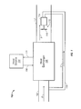
- FIG. 1 is a block diagram illustrating a system in which embodiments of the present invention can be implemented
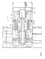
- FIG. 2 is cut-away view of a fan according to one embodiment of the present invention.
- FIG. 3 is a cross-section of an inner diameter heat exchanger
- FIG. 4 is a graph showing simulated temperature variations for a rotor according to the prior art and one embodiment of the present invention.
- FIG. 5 is a cut-away side view of a heat pipe according to one embodiment of the present invention coupled between an inner diameter heat exchanger and an air movement implement.
- FIG. 1 illustrates a system 100 in which embodiments of the present invention may be implemented.
- the system 100 can be part of an aircraft or any other type of device that can cause the system 100 to be moved in a forward direction.
- Embodiments of the present invention are directed to a motor 114 that can be used in the system 100.
- the motor 114 can include a heat pipe that is used to cool or heat the rotor thereof.
- the heat pipe causes the range of a rotor temperature cycle to be reduced as compared to motors that do not include a heat pipe.
- the motor 114 is part of a fan 115 that includes an air movement implement such as a fan blade or impeller generally shown by element 116.
- the motor 114 can be an induction motor in one embodiment but it shall be understood that the motor 114 could be any type of electric motor including, for example, a synchronous motor, a DC motor or a slip-ring AC motor to name but a few.
- the fan 115 is arranged downstream of a heat exchanger 106.
- the terms upstream and downstream refer to the direction of travel of a substance (e.g., air) through a system. In particular, a position is upstream of another position if it is closer to the entry to the system than the other position.
- the heat exchanger 106 is upstream of the fan 115.
- the fan 115 is downstream of heat exchanger 106.
- a heat source 104 is provided from which heat is drawn.
- a cooling fluid circulates through the heat source 104 and is heated therein.
- the heated fluid is provided through output connection 108 to the heat exchanger 106.
- the fluid is cooled as it passes through the heat exchanger 106 and is returned through input connection 110 to the heat source 104 where it can again be used to remove heat from it.
- the heat source 104 includes some or all of the electronics that operate in an aircraft. It shall be understood, however, that the heat source 104 can be any device or system that generates heat and the heat can be carried from it by means other than a fluid.
- the fan 115 causes input air (illustrated by arrow A) to be drawn into an input portion 102, through the heat exchanger 106, and through an output portion 112 where it is expelled back into the atmosphere as output air (illustrated by arrow B).
- a cooling duct 118 is coupled to the input portion 102 such that at least a portion of air drawn into the input portion 102 is diverted to the motor 114 before the air is heated in the heat exchanger 106.
- Such air shall be referred to herein as "cooling air” and is illustrated by arrow C.
- the fan 115 In operation, while the system 100 is at rest (e.g., an aircraft is on the ground) the fan 115 is required to draw in input air A. In such a case, the input air A is at a temperature generally in the 0 to 120 degrees F (-17 to 40 degrees C) range while the output air B is about 200 degrees F (93.3 degrees C). In such a case, the rotor of motor 114 is at a temperature of about 190 degrees F (87.7 degrees C). When the system 100 is motion (e.g., the aircraft is cruising), the motion of the system 100 is all that is need to cause input air A to pass through the heat exchanger 106. In such a case, the motor 114 can be turned off. The motor 114, however, is still cooled with cooling air C.
- the cooling air C is in the range of about -15 degrees F (-26.1 degrees C).
- the motor housing is heated by the output air B (at about 200 degrees F (93.3 degrees C)).
- the heating of the motor housing can heat the rotor to about -10 degrees F (-23.3 degrees C).
- the rotor of motor 114 can experience a 200 degrees F (93.3 degrees C) or more temperature variation each time the system starts and stops moving.
- FIG. 2 shows a cut-away side view of fan 115 according to one embodiment.
- the fan 115 includes air movement implement 116 (e.g., fan or impeller blade) that is coupled to and driven by motor 114.
- the motor 114 includes an outer shell 200 that surrounds a rotor 203 and a stator 208.
- the rotor 203 includes, in this embodiment, a tie rod 204 coupled to and surrounded by an inner diameter heat exchanger 206.
- the rotor 203 can include one or more windings 205 disposed between the inner diameter heat exchanger 206 and the stator 208.
- An inner diameter or internal diameter heat sink is one that is located within a cylindrical part of the rotor, such as radially within the windings.
- the rotor 203 is coupled to and provides a driving force to air movement implement 116 by a shaft 220.
- a heat pipe 202 is coupled to the air movement implement 116 and the inner diameter heat exchanger 206. As illustrated, the heat pipe 202 is within the shaft 220 but the relative locations could be varied based on how the shaft 220 is coupled to the rotor 203.
- FIG. 3 is a cross-section of the rotor 203 taken along lines A-A.
- the rotor 203 includes the tie rod 204 surrounded by the inner diameter heat exchanger 206.
- the inner diameter heat exchanger 206 includes an outer shell 302 that defines an outer perimeter thereof and an inner layer 304.
- One or more fins 306 extend radially between the inner layer 304 and the outer shell 302. The fins 306 define one or more air channels 308 through which cooling air can pass.
- the cooling air C received via cooling duct 118 can travel through several different paths.
- a portion of the cooling air C illustrated as C r can pass through the inner diameter heat exchanger 206.
- This air serves to generally cool the rotor 203.
- the rotor 203 can also be cooled by a portion of the cooling air C illustrated as C r-s that passes between the rotor 203 and the stator 208 as well as portion C s that passes between the stator 208 and the outer shell 200.
- the temperature of the rotor 203 will first be explained assuming that the heat pipe 202 is omitted and then explained with the heat pipe 202 included.
- the fan 115 is arranged in a system as illustrated in FIG. 1 and that the system is part of an aircraft. It shall be understood that the fan 115 need not be disposed in any particular system.
- the cooling air C can have a maximum temperature of about 130 degrees F (54.4 degrees C) and the output air B has a maximum temperature of about 210 degrees F (98.8 degrees C).
- the rotor 203 can have a temperature that is about 190 degrees F (87.7 degrees C).
- the motor 114 can be turned off. The motor 114, however, still receives cooling air C and the cooling air C is now much colder (in the range of about -10 degrees F (-23.3 degrees C)) than when the aircraft was on the ground.
- the output air B can warm the outer shell 200 and, to some extent, the stator 208.
- the rotor 203 becomes much colder due to the cooling air C as described above.
- FIG. 4 graphically shows simulations of the temperature of the rotor 203 as the aircraft is on the ground, in flight, and lands again.
- Trace 402 represents this cycle for the configuration that does not include a heat pipe according to the present invention.
- Peaks 404 and 406 represent the rotor temperature when the aircraft is on the ground and valley 408 represents the rotor temperature when the aircraft is in-flight.
- the rotor temperature 402 can vary by around 200 degrees F (93.3 degrees C) in such a case.
- trace 410 illustrates the rotor temperature for the same cycle when the heat pipe 202 is added.
- the heat pipe 202 lowers the ground rotor temperature (peak 412) because it allows some of the heat to be dissipated through the air movement implement 116.
- the heat pipe 202 can allow heat from the air movement device to be transferred to the rotor 203 when the aircraft is in flight and, thereby, raise the in-flight rotor temperature (valley 414). In one embodiment, only the valley 414 is raised and peak 412 is at about the same level as the peaks 404, 406.
- the heat pipe 202 is illustrated as being solid. It shall be understood that in another embodiment, the heat pipe can include an inner cavity formed therein. In either case, the heat pipe 202 can be arranged such that it contacts an end of the inner diameter heat exchanger 206 and provides a thermal pathway between it and the air movement implement 116.
- FIG. 5 shows a detail in cross-section of the heat pipe 202.
- the heat pipe 202 is in thermal contact with an end 502 of the inner diameter heat exchanger 206 and the air movement implement 116.
- heat is received from the rotor windings (not shown) as indicated by arrows D. This heat is dissipated by the passage of rotor cooling air C r .
- the heat pipe 202 further dissipates the heat.
- the heat pipe 202 can provide a thermal pathway to the air movement implement 116 such that heat (shown by arrows E) can travel out of blades 504 of the air movement implement 116.
- the heat pipe 202 can be formed of two or more different portions. As illustrated, the heat pipe 202 is annular and includes an inner shell 510, ends 512 and outer shell 514. In one embodiment, the ends 512 and outer shell 514 are formed of a single piece. In one embodiment, the inner shell 510 is formed of a material with a lower thermal conductivity than one or both of the outer shell 514 and the ends 512. The inner shell 510 can be formed of copper, aluminum, ULTEM or any other suitable plastic material and one or both of outer shell 514 and the ends 512 can be formed of copper or aluminum.
- the heat pipe 202 includes a cavity 505 formed between the inner and outer shells 510, 514.
- the cavity 504 can have a width w that decreases as the distance from the internal diameter heat exchanger 206 increases.
- the inner shell 510 is substantially cylindrical and has a constant thickness while the outer shell 514 has thickness that varies such that the width w varies as described above.
- the cavity 505 can be filled with a fluid.
- the fluid is one of methanol or ammonia. It shall be understood that the fluid should remain in the liquid state at the coldest expected temperature to which it will be exposed.
- the inner shell 510, the ends 512 and the outer shell 514 are crimped together. In another, they are ultrasonically welded together.
- the cavity 505 shall be described as having narrow end 530 and wide end 532.
- the width w is largest at the wide end 532 and smallest at the narrow end 530.
- the narrow end 530 is located at or near the air movement implement 116 and the wide end 532 abuts the inner diameter heat exchanger 206.
- the inner diameter ID of the heat pipe 202 is less than the outer diameter OD of the inner diameter heat exchanger 206 in one embodiment.
- the fluid can aid in dissipating heat from the rotor while the system in which the motor is placed is stationary (i.e., the aircraft is on the ground).
- heat from the inner diameter heat exchanger 206 can cause the fluid to convert to a vapor or gas. Due to the latent heat of fusion, this change of state can dissipate heat in and of itself.
- the vapor/gas expands and travels towards the narrow end 530 as indicated by arrows F.
- the air movement implement 116 As the vapor/gas reaches the narrow end 530, its heat can be transferred to the air movement implement 116 and bled off by output air B through blades 504.
- the rotation of the air movement implement 116 and, thus, the heat pipe 202 causes the fluid to track the outer shell 514 and travel back towards the wide end 532 as indicated by arrows G where the process can be repeated.
- the rotor cooling air C r can be much colder than when the system 100 was stationary as described above.
- the heat pipe 202 itself and the fluid can provide a path for heat from the output air B to travel from the blades 504 back into the inner diameter heat exchanger 206 and, consequently, reduce the cooling effect of the rotor cooling air C r .
Landscapes
- Engineering & Computer Science (AREA)
- Mechanical Engineering (AREA)
- General Engineering & Computer Science (AREA)
- Physics & Mathematics (AREA)
- Thermal Sciences (AREA)
- Life Sciences & Earth Sciences (AREA)
- Sustainable Development (AREA)
- Power Engineering (AREA)
- Motor Or Generator Cooling System (AREA)
Abstract
Description
- The present invention is related to motors and, in particular, to reducing the temperature variations experienced by a rotor of a motor.
- In many different applications, a motor or other machine that includes a rotor that can be placed in systems where it experiences a wide range of temperatures. For example, an induction motor can be used to drive an impeller that draws air through a heat exchanger in an aircraft. The combination of the motor and the impeller is sometimes referred to as a ram air fan. While the aircraft is on the ground, outside air is drawn by the ram air fan through the heat exchanger. The air is used to carry heat away from the heat exchanger. Internal portions of the ram air fan are cooled by cooling air that is diverted around the heat exchanger. When the aircraft is in flight, the cooling air is significantly colder than when it is on the ground. As such, the internal portions of the motor (e.g., the rotor) can experience wide-ranging temperature cycles that can result in shortened lifecycles for the rotor.
- According to one embodiment, a fan that includes an air movement implement including a blade and a motor that drives the air movement implement is disclosed. The motor in this embodiment includes a rotor that includes an internal diameter heat exchanger and a heat pipe having a first end and a second end, the first end in thermal contact with the internal diameter heat exchanger and the second end in thermal contact with the blade.
- According to another embodiment, a system that includes an air intake, a heat exchanger coupled to the air intake, an air output coupled to the air heat exchanger, and a fan disposed within the air output that causes air to be drawn in the air intake, through the heat exchanger and expelled through the air output is disclosed. The fan includes an air movement implement including a blade and a motor that drives the air movement implement. The motor includes a rotor that includes an internal diameter heat exchanger and a heat pipe having a first end and a second end, the first end in thermal contact with the internal diameter heat exchanger and the second end in thermal contact with the blade.
- The subject matter which is regarded as the invention is particularly pointed out and distinctly claimed in the claims at the conclusion of the specification. The foregoing and other features, and advantages of the invention are apparent from the following detailed description taken in conjunction with the accompanying drawings in which:
-
FIG. 1 is a block diagram illustrating a system in which embodiments of the present invention can be implemented; -
FIG. 2 is cut-away view of a fan according to one embodiment of the present invention; -
FIG. 3 is a cross-section of an inner diameter heat exchanger; -
FIG. 4 is a graph showing simulated temperature variations for a rotor according to the prior art and one embodiment of the present invention; and -
FIG. 5 is a cut-away side view of a heat pipe according to one embodiment of the present invention coupled between an inner diameter heat exchanger and an air movement implement. -
FIG. 1 illustrates asystem 100 in which embodiments of the present invention may be implemented. Thesystem 100 can be part of an aircraft or any other type of device that can cause thesystem 100 to be moved in a forward direction. Embodiments of the present invention are directed to amotor 114 that can be used in thesystem 100. According to one embodiment, themotor 114 can include a heat pipe that is used to cool or heat the rotor thereof. In one embodiment, the heat pipe causes the range of a rotor temperature cycle to be reduced as compared to motors that do not include a heat pipe. - In
FIG. 1 , themotor 114 is part of afan 115 that includes an air movement implement such as a fan blade or impeller generally shown byelement 116. Themotor 114 can be an induction motor in one embodiment but it shall be understood that themotor 114 could be any type of electric motor including, for example, a synchronous motor, a DC motor or a slip-ring AC motor to name but a few. InFIG. 1 , thefan 115 is arranged downstream of aheat exchanger 106. The terms upstream and downstream refer to the direction of travel of a substance (e.g., air) through a system. In particular, a position is upstream of another position if it is closer to the entry to the system than the other position. For example, inFIG. 1 , assuming that air travels in the direction shown by arrows A, theheat exchanger 106 is upstream of thefan 115. Further, and in the same vein, thefan 115 is downstream ofheat exchanger 106. - In operation, a
heat source 104 is provided from which heat is drawn. A cooling fluid circulates through theheat source 104 and is heated therein. The heated fluid is provided throughoutput connection 108 to theheat exchanger 106. The fluid is cooled as it passes through theheat exchanger 106 and is returned throughinput connection 110 to theheat source 104 where it can again be used to remove heat from it. In one embodiment, theheat source 104 includes some or all of the electronics that operate in an aircraft. It shall be understood, however, that theheat source 104 can be any device or system that generates heat and the heat can be carried from it by means other than a fluid. - In
FIG. 1 , thefan 115 causes input air (illustrated by arrow A) to be drawn into aninput portion 102, through theheat exchanger 106, and through anoutput portion 112 where it is expelled back into the atmosphere as output air (illustrated by arrow B). Acooling duct 118 is coupled to theinput portion 102 such that at least a portion of air drawn into theinput portion 102 is diverted to themotor 114 before the air is heated in theheat exchanger 106. Such air shall be referred to herein as "cooling air" and is illustrated by arrow C. - In operation, while the
system 100 is at rest (e.g., an aircraft is on the ground) thefan 115 is required to draw in input air A. In such a case, the input air A is at a temperature generally in the 0 to 120 degrees F (-17 to 40 degrees C) range while the output air B is about 200 degrees F (93.3 degrees C). In such a case, the rotor ofmotor 114 is at a temperature of about 190 degrees F (87.7 degrees C). When thesystem 100 is motion (e.g., the aircraft is cruising), the motion of thesystem 100 is all that is need to cause input air A to pass through theheat exchanger 106. In such a case, themotor 114 can be turned off. Themotor 114, however, is still cooled with cooling air C. In such instances, the cooling air C is in the range of about -15 degrees F (-26.1 degrees C). The motor housing is heated by the output air B (at about 200 degrees F (93.3 degrees C)). The heating of the motor housing can heat the rotor to about -10 degrees F (-23.3 degrees C). Given the above example, it can readily be realized that the rotor ofmotor 114 can experience a 200 degrees F (93.3 degrees C) or more temperature variation each time the system starts and stops moving. -
FIG. 2 shows a cut-away side view offan 115 according to one embodiment. Thefan 115 includes air movement implement 116 (e.g., fan or impeller blade) that is coupled to and driven bymotor 114. Themotor 114 includes anouter shell 200 that surrounds arotor 203 and astator 208. Therotor 203 includes, in this embodiment, atie rod 204 coupled to and surrounded by an innerdiameter heat exchanger 206. In the case where themotor 114 is an induction motor, therotor 203 can include one ormore windings 205 disposed between the innerdiameter heat exchanger 206 and thestator 208. An inner diameter or internal diameter heat sink is one that is located within a cylindrical part of the rotor, such as radially within the windings. As is known in the art, therotor 203 is coupled to and provides a driving force to air movement implement 116 by a shaft 220. According to one embodiment, aheat pipe 202 is coupled to the air movement implement 116 and the innerdiameter heat exchanger 206. As illustrated, theheat pipe 202 is within the shaft 220 but the relative locations could be varied based on how the shaft 220 is coupled to therotor 203. -
FIG. 3 is a cross-section of therotor 203 taken along lines A-A. Therotor 203 includes thetie rod 204 surrounded by the innerdiameter heat exchanger 206. In this embodiment, the innerdiameter heat exchanger 206 includes anouter shell 302 that defines an outer perimeter thereof and aninner layer 304. One ormore fins 306 extend radially between theinner layer 304 and theouter shell 302. Thefins 306 define one ormore air channels 308 through which cooling air can pass. - Referring again to
FIG. 2 , the cooling air C received via cooling duct 118 (FIG. 1 ) can travel through several different paths. For instance, a portion of the cooling air C illustrated as Cr can pass through the innerdiameter heat exchanger 206. This air serves to generally cool therotor 203. Therotor 203 can also be cooled by a portion of the cooling air C illustrated as Cr-s that passes between therotor 203 and thestator 208 as well as portion Cs that passes between thestator 208 and theouter shell 200. - The temperature of the
rotor 203 will first be explained assuming that theheat pipe 202 is omitted and then explained with theheat pipe 202 included. In the following explanation it shall be assumed that thefan 115 is arranged in a system as illustrated inFIG. 1 and that the system is part of an aircraft. It shall be understood that thefan 115 need not be disposed in any particular system. - While on the ground, the cooling air C can have a maximum temperature of about 130 degrees F (54.4 degrees C) and the output air B has a maximum temperature of about 210 degrees F (98.8 degrees C). In such a case, the
rotor 203 can have a temperature that is about 190 degrees F (87.7 degrees C). When the aircraft is in flight, themotor 114 can be turned off. Themotor 114, however, still receives cooling air C and the cooling air C is now much colder (in the range of about -10 degrees F (-23.3 degrees C)) than when the aircraft was on the ground. In flight, the output air B can warm theouter shell 200 and, to some extent, thestator 208. Therotor 203, however, becomes much colder due to the cooling air C as described above. -
FIG. 4 graphically shows simulations of the temperature of therotor 203 as the aircraft is on the ground, in flight, and lands again.Trace 402 represents this cycle for the configuration that does not include a heat pipe according to the present invention.Peaks valley 408 represents the rotor temperature when the aircraft is in-flight. As described above, therotor temperature 402 can vary by around 200 degrees F (93.3 degrees C) in such a case. - In contrast,
trace 410 illustrates the rotor temperature for the same cycle when theheat pipe 202 is added. In general, theheat pipe 202 lowers the ground rotor temperature (peak 412) because it allows some of the heat to be dissipated through the air movement implement 116. Likewise, theheat pipe 202 can allow heat from the air movement device to be transferred to therotor 203 when the aircraft is in flight and, thereby, raise the in-flight rotor temperature (valley 414). In one embodiment, only the valley 414 is raised andpeak 412 is at about the same level as thepeaks - Referring again to
FIG. 2 , theheat pipe 202 is illustrated as being solid. It shall be understood that in another embodiment, the heat pipe can include an inner cavity formed therein. In either case, theheat pipe 202 can be arranged such that it contacts an end of the innerdiameter heat exchanger 206 and provides a thermal pathway between it and the air movement implement 116. -
FIG. 5 shows a detail in cross-section of theheat pipe 202. Theheat pipe 202 is in thermal contact with anend 502 of the innerdiameter heat exchanger 206 and the air movement implement 116. InFIG. 5 , while on the ground, heat is received from the rotor windings (not shown) as indicated by arrows D. This heat is dissipated by the passage of rotor cooling air Cr. Theheat pipe 202 further dissipates the heat. In particular, theheat pipe 202 can provide a thermal pathway to the air movement implement 116 such that heat (shown by arrows E) can travel out ofblades 504 of the air movement implement 116. - The
heat pipe 202 can be formed of two or more different portions. As illustrated, theheat pipe 202 is annular and includes aninner shell 510, ends 512 andouter shell 514. In one embodiment, theends 512 andouter shell 514 are formed of a single piece. In one embodiment, theinner shell 510 is formed of a material with a lower thermal conductivity than one or both of theouter shell 514 and the ends 512. Theinner shell 510 can be formed of copper, aluminum, ULTEM or any other suitable plastic material and one or both ofouter shell 514 and theends 512 can be formed of copper or aluminum. - In one embodiment, the
heat pipe 202 includes acavity 505 formed between the inner andouter shells cavity 504 can have a width w that decreases as the distance from the internaldiameter heat exchanger 206 increases. In one embodiment, theinner shell 510 is substantially cylindrical and has a constant thickness while theouter shell 514 has thickness that varies such that the width w varies as described above. - In one embodiment, the
cavity 505 can be filled with a fluid. In one embodiment, the fluid is one of methanol or ammonia. It shall be understood that the fluid should remain in the liquid state at the coldest expected temperature to which it will be exposed. In one embodiment, theinner shell 510, theends 512 and theouter shell 514 are crimped together. In another, they are ultrasonically welded together. - For ease of explanation, the
cavity 505 shall be described as havingnarrow end 530 andwide end 532. The width w is largest at thewide end 532 and smallest at thenarrow end 530. In one embodiment, thenarrow end 530 is located at or near the air movement implement 116 and thewide end 532 abuts the innerdiameter heat exchanger 206. The inner diameter ID of theheat pipe 202 is less than the outer diameter OD of the innerdiameter heat exchanger 206 in one embodiment. - In one embodiment, the fluid can aid in dissipating heat from the rotor while the system in which the motor is placed is stationary (i.e., the aircraft is on the ground). In particular, heat from the inner
diameter heat exchanger 206 can cause the fluid to convert to a vapor or gas. Due to the latent heat of fusion, this change of state can dissipate heat in and of itself. The vapor/gas expands and travels towards thenarrow end 530 as indicated by arrows F. As the vapor/gas reaches thenarrow end 530, its heat can be transferred to the air movement implement 116 and bled off by output air B throughblades 504. As the vapor/gas loses its heat, it returns to the liquid phase. The rotation of the air movement implement 116 and, thus, theheat pipe 202, causes the fluid to track theouter shell 514 and travel back towards thewide end 532 as indicated by arrows G where the process can be repeated. - When the
system 100 in which themotor 114 is placed is in motion, the rotor cooling air Cr can be much colder than when thesystem 100 was stationary as described above. In such a case, theheat pipe 202 itself and the fluid can provide a path for heat from the output air B to travel from theblades 504 back into the innerdiameter heat exchanger 206 and, consequently, reduce the cooling effect of the rotor cooling air Cr. - While the invention has been described in detail in connection with only a limited number of embodiments, it should be readily understood that the invention is not limited to such disclosed embodiments. Rather, the invention can be modified to incorporate any number of variations, alterations, substitutions or equivalent arrangements not heretofore described, but which are commensurate with the scope of the invention. Additionally, while various embodiments of the invention have been described, it is to be understood that aspects of the invention may include only some of the described embodiments. Accordingly, the invention is not to be seen as limited by the foregoing description, but is only limited by the scope of the appended claims.
Claims (11)
- A fan (115) comprising:an air movement implement (116) including a blade (504); anda motor (114) that drives the air movement implement and includes:a rotor (203) that includes an internal diameter heat exchanger (206); anda heat pipe (202) having a first end and a second end (512), the first end being in thermal contact with the internal diameter heat exchanger (206) and the second end in thermal contact with the blade (504).
- The fan of claim 1, wherein the heat pipe (202) includes an internal cavity (505).
- The fan of claim 2, wherein the internal cavity (505) includes a cooling fluid.
- The fan of claim 3, wherein the cooling fluid is one of: methanol and ammonia.
- The fan of claim 2, 3 or 4, wherein the internal cavity has a width (w) that decreases from the first end to the second end (512).
- The fan of any preceding claim, wherein the heat pipe (202) is an annular heat pipe.
- The fan of any preceding claim, wherein the heat pipe includes inner (510) and outer (514) shells and the inner shell has a lower thermal conductivity than the outer shell.
- A system (100) comprising:an air intake (102);a heat exchanger (106) coupled to the air intake;an air output (112) coupled to the air heat exchanger; anda fan (115) as claimed in any preceding claim disposed within the air output that causes air to be drawn in the air intake, through the heat exchanger and expelled through the air output.
- The system of claim 8, wherein the heat exchanger (106) is coupled to a cooling system (104) of an aircraft.
- The system of claim 8 or 9, wherein the air intake (102), the heat exchanger (106) and the air output (112) are part of an aircraft.
- The system of claim 8, 9 or 10, further comprising:a cooling duct (118) coupled between the air intake (102) and the motor (114) that provides air that has not passed through the heat exchanger (106) to the motor (114).
Applications Claiming Priority (1)
| Application Number | Priority Date | Filing Date | Title |
|---|---|---|---|
| US13/190,824 US8884480B2 (en) | 2011-07-26 | 2011-07-26 | Motor with cooled rotor |
Publications (3)
| Publication Number | Publication Date |
|---|---|
| EP2551528A2 true EP2551528A2 (en) | 2013-01-30 |
| EP2551528A3 EP2551528A3 (en) | 2017-10-18 |
| EP2551528B1 EP2551528B1 (en) | 2020-10-14 |
Family
ID=46603644
Family Applications (1)
| Application Number | Title | Priority Date | Filing Date |
|---|---|---|---|
| EP12178125.6A Active EP2551528B1 (en) | 2011-07-26 | 2012-07-26 | Motor with cooled rotor |
Country Status (2)
| Country | Link |
|---|---|
| US (2) | US8884480B2 (en) |
| EP (1) | EP2551528B1 (en) |
Families Citing this family (8)
| Publication number | Priority date | Publication date | Assignee | Title |
|---|---|---|---|---|
| US9819239B2 (en) | 2015-05-07 | 2017-11-14 | Hamilton Sundstrand Corporation | End winding support and heat sink for liquid-cooled generator |
| EP3869043A1 (en) * | 2015-06-01 | 2021-08-25 | SZ DJI Technology Co., Ltd. | System, kit, and method for dissipating heat generated by a motor assembly |
| US11122715B2 (en) | 2018-05-11 | 2021-09-14 | General Electric Company | Conformal heat pipe assemblies |
| US11092024B2 (en) | 2018-10-09 | 2021-08-17 | General Electric Company | Heat pipe in turbine engine |
| DE102019208039A1 (en) * | 2019-06-03 | 2020-12-03 | Zf Friedrichshafen Ag | Electric machine with a rotor cooling device |
| CN113290826A (en) * | 2021-06-02 | 2021-08-24 | 苏州固泰新材股份有限公司 | Circulating cooling water device for extruder barrel and cooling method |
| US12078105B2 (en) | 2022-06-14 | 2024-09-03 | General Electric Company | System and method for providing cooling in a compressor section of a gas turbine engine |
| US12486800B2 (en) * | 2024-04-19 | 2025-12-02 | Rtx Corporation | Powerplant with integrated heat pipe |
Family Cites Families (12)
| Publication number | Priority date | Publication date | Assignee | Title |
|---|---|---|---|---|
| US3568762A (en) * | 1967-05-23 | 1971-03-09 | Rca Corp | Heat pipe |
| CH516251A (en) * | 1969-01-04 | 1971-11-30 | Siemens Ag | Method for cooling a fixed body rotatable about a hollow shaft |
| DE2220266A1 (en) * | 1972-04-25 | 1973-11-08 | Siemens Ag | ARRANGEMENT FOR COOLING THE RUNNER OF AN ELECTRIC MACHINE USING A HEAT PIPE |
| US4012770A (en) * | 1972-09-28 | 1977-03-15 | Dynatherm Corporation | Cooling a heat-producing electrical or electronic component |
| US4137472A (en) * | 1974-01-31 | 1979-01-30 | S.B.W. Engineers Limited | Cooling system for electric motors |
| US4102770A (en) | 1977-07-18 | 1978-07-25 | American Chemical And Refining Company Incorporated | Electroplating test cell |
| JPS5635869U (en) * | 1979-08-27 | 1981-04-07 | ||
| JPS5678353A (en) * | 1979-11-29 | 1981-06-27 | Fanuc Ltd | Cooling fin for rotary machine |
| US8283818B2 (en) * | 2006-06-19 | 2012-10-09 | Hpev, Inc. | Electric motor with heat pipes |
| US8148858B2 (en) * | 2008-08-06 | 2012-04-03 | Hpev, Inc. | Totally enclosed heat pipe cooled motor |
| US8018110B2 (en) * | 2009-04-30 | 2011-09-13 | General Electric Company | High speed internal permanent magnet machine and method of manufacturing the same |
| TWI424663B (en) * | 2010-07-01 | 2014-01-21 | Joy Ride Tech Co Ltd | A motor with heat pipe |
-
2011
- 2011-07-26 US US13/190,824 patent/US8884480B2/en active Active
-
2012
- 2012-07-26 EP EP12178125.6A patent/EP2551528B1/en active Active
-
2014
- 2014-07-30 US US14/446,892 patent/US9671172B2/en active Active
Non-Patent Citations (1)
| Title |
|---|
| None |
Also Published As
| Publication number | Publication date |
|---|---|
| US20130025828A1 (en) | 2013-01-31 |
| EP2551528B1 (en) | 2020-10-14 |
| US20150300749A1 (en) | 2015-10-22 |
| US9671172B2 (en) | 2017-06-06 |
| US8884480B2 (en) | 2014-11-11 |
| EP2551528A3 (en) | 2017-10-18 |
Similar Documents
| Publication | Publication Date | Title |
|---|---|---|
| US9671172B2 (en) | Motor with cooled rotor | |
| US9178400B2 (en) | Cooling arrangement for a motor assembly and method of cooling a motor assembly | |
| US9331552B2 (en) | Rotor assembly with heat pipe cooling system | |
| US9593594B2 (en) | Method and apparatus for decongealing a lubricating fluid in a heat exchanger apparatus | |
| CN104242549B (en) | Use the cooling of the motor of radially installed fan | |
| US9413208B2 (en) | Enhanced cooling of enclosed air cooled high power motors | |
| CN104246227B (en) | electric motor driven pump | |
| JP2017137047A (en) | Aircraft thermal management system | |
| WO2005039036A3 (en) | Improved belt drive system with outer rotor motor | |
| US9638105B2 (en) | Turbine engine incorporating thermoelectric generators | |
| CN111357170B (en) | Electric machine of a turbomachine comprising a rotor cooled by a cooling channel | |
| EP2258948A2 (en) | Improved refrigerant compressor | |
| EP2752977A2 (en) | Cooling system for an electric machine and method of assembly of same | |
| Raimondo et al. | Development of direct oil cooling solutions for e-mobility traction motors: Part ii: Rotor cooling concept | |
| EP2490323A2 (en) | Cooling of permanent magnet electric machine | |
| Mesalhy et al. | Study of a high-reliability dual-fan system for cooling aerospace electromechanical actuators | |
| US11165309B2 (en) | Motor cooling system and method | |
| US8975838B2 (en) | Electric motor braking using thermoelectric cooling | |
| EP2852036A1 (en) | Electric machine with closed circuit air cooling | |
| JP6413640B2 (en) | Compressor | |
| EP3163722A1 (en) | Laminated stator with cooling lamination layers | |
| US12368349B2 (en) | Composite two-phase fluid cooling motor and composite two-phase fluid cooling device thereof | |
| JP5273232B2 (en) | Electric compressor | |
| US11038390B2 (en) | Electrical machine apparatus having a conduit with a particular arrangement for an inlet and outlet | |
| CN105684275A (en) | Fan directing element for an electric machine |
Legal Events
| Date | Code | Title | Description |
|---|---|---|---|
| PUAI | Public reference made under article 153(3) epc to a published international application that has entered the european phase |
Free format text: ORIGINAL CODE: 0009012 |
|
| AK | Designated contracting states |
Kind code of ref document: A2 Designated state(s): AL AT BE BG CH CY CZ DE DK EE ES FI FR GB GR HR HU IE IS IT LI LT LU LV MC MK MT NL NO PL PT RO RS SE SI SK SM TR |
|
| AX | Request for extension of the european patent |
Extension state: BA ME |
|
| REG | Reference to a national code |
Ref country code: DE Ref legal event code: R079 Ref document number: 602012072771 Country of ref document: DE Free format text: PREVIOUS MAIN CLASS: F04D0025080000 Ipc: F04D0019000000 |
|
| PUAL | Search report despatched |
Free format text: ORIGINAL CODE: 0009013 |
|
| AK | Designated contracting states |
Kind code of ref document: A3 Designated state(s): AL AT BE BG CH CY CZ DE DK EE ES FI FR GB GR HR HU IE IS IT LI LT LU LV MC MK MT NL NO PL PT RO RS SE SI SK SM TR |
|
| AX | Request for extension of the european patent |
Extension state: BA ME |
|
| RIC1 | Information provided on ipc code assigned before grant |
Ipc: F04D 29/58 20060101ALI20170914BHEP Ipc: F04D 25/06 20060101ALI20170914BHEP Ipc: F04D 25/08 20060101ALI20170914BHEP Ipc: F04D 29/32 20060101ALI20170914BHEP Ipc: F04D 19/00 20060101AFI20170914BHEP |
|
| STAA | Information on the status of an ep patent application or granted ep patent |
Free format text: STATUS: REQUEST FOR EXAMINATION WAS MADE |
|
| 17P | Request for examination filed |
Effective date: 20180418 |
|
| RBV | Designated contracting states (corrected) |
Designated state(s): AL AT BE BG CH CY CZ DE DK EE ES FI FR GB GR HR HU IE IS IT LI LT LU LV MC MK MT NL NO PL PT RO RS SE SI SK SM TR |
|
| STAA | Information on the status of an ep patent application or granted ep patent |
Free format text: STATUS: EXAMINATION IS IN PROGRESS |
|
| 17Q | First examination report despatched |
Effective date: 20191030 |
|
| GRAP | Despatch of communication of intention to grant a patent |
Free format text: ORIGINAL CODE: EPIDOSNIGR1 |
|
| STAA | Information on the status of an ep patent application or granted ep patent |
Free format text: STATUS: GRANT OF PATENT IS INTENDED |
|
| INTG | Intention to grant announced |
Effective date: 20200429 |
|
| RAP1 | Party data changed (applicant data changed or rights of an application transferred) |
Owner name: HAMILTON SUNDSTRAND CORPORATION |
|
| GRAS | Grant fee paid |
Free format text: ORIGINAL CODE: EPIDOSNIGR3 |
|
| GRAA | (expected) grant |
Free format text: ORIGINAL CODE: 0009210 |
|
| STAA | Information on the status of an ep patent application or granted ep patent |
Free format text: STATUS: THE PATENT HAS BEEN GRANTED |
|
| AK | Designated contracting states |
Kind code of ref document: B1 Designated state(s): AL AT BE BG CH CY CZ DE DK EE ES FI FR GB GR HR HU IE IS IT LI LT LU LV MC MK MT NL NO PL PT RO RS SE SI SK SM TR |
|
| REG | Reference to a national code |
Ref country code: GB Ref legal event code: FG4D |
|
| REG | Reference to a national code |
Ref country code: AT Ref legal event code: REF Ref document number: 1323872 Country of ref document: AT Kind code of ref document: T Effective date: 20201015 Ref country code: CH Ref legal event code: EP |
|
| REG | Reference to a national code |
Ref country code: DE Ref legal event code: R096 Ref document number: 602012072771 Country of ref document: DE |
|
| REG | Reference to a national code |
Ref country code: IE Ref legal event code: FG4D |
|
| REG | Reference to a national code |
Ref country code: AT Ref legal event code: MK05 Ref document number: 1323872 Country of ref document: AT Kind code of ref document: T Effective date: 20201014 |
|
| REG | Reference to a national code |
Ref country code: NL Ref legal event code: MP Effective date: 20201014 |
|
| PG25 | Lapsed in a contracting state [announced via postgrant information from national office to epo] |
Ref country code: RS Free format text: LAPSE BECAUSE OF FAILURE TO SUBMIT A TRANSLATION OF THE DESCRIPTION OR TO PAY THE FEE WITHIN THE PRESCRIBED TIME-LIMIT Effective date: 20201014 Ref country code: FI Free format text: LAPSE BECAUSE OF FAILURE TO SUBMIT A TRANSLATION OF THE DESCRIPTION OR TO PAY THE FEE WITHIN THE PRESCRIBED TIME-LIMIT Effective date: 20201014 Ref country code: NO Free format text: LAPSE BECAUSE OF FAILURE TO SUBMIT A TRANSLATION OF THE DESCRIPTION OR TO PAY THE FEE WITHIN THE PRESCRIBED TIME-LIMIT Effective date: 20210114 Ref country code: PT Free format text: LAPSE BECAUSE OF FAILURE TO SUBMIT A TRANSLATION OF THE DESCRIPTION OR TO PAY THE FEE WITHIN THE PRESCRIBED TIME-LIMIT Effective date: 20210215 Ref country code: NL Free format text: LAPSE BECAUSE OF FAILURE TO SUBMIT A TRANSLATION OF THE DESCRIPTION OR TO PAY THE FEE WITHIN THE PRESCRIBED TIME-LIMIT Effective date: 20201014 Ref country code: GR Free format text: LAPSE BECAUSE OF FAILURE TO SUBMIT A TRANSLATION OF THE DESCRIPTION OR TO PAY THE FEE WITHIN THE PRESCRIBED TIME-LIMIT Effective date: 20210115 |
|
| REG | Reference to a national code |
Ref country code: LT Ref legal event code: MG4D |
|
| RAP4 | Party data changed (patent owner data changed or rights of a patent transferred) |
Owner name: HAMILTON SUNDSTRAND CORPORATION |
|
| PG25 | Lapsed in a contracting state [announced via postgrant information from national office to epo] |
Ref country code: SE Free format text: LAPSE BECAUSE OF FAILURE TO SUBMIT A TRANSLATION OF THE DESCRIPTION OR TO PAY THE FEE WITHIN THE PRESCRIBED TIME-LIMIT Effective date: 20201014 Ref country code: LV Free format text: LAPSE BECAUSE OF FAILURE TO SUBMIT A TRANSLATION OF THE DESCRIPTION OR TO PAY THE FEE WITHIN THE PRESCRIBED TIME-LIMIT Effective date: 20201014 Ref country code: PL Free format text: LAPSE BECAUSE OF FAILURE TO SUBMIT A TRANSLATION OF THE DESCRIPTION OR TO PAY THE FEE WITHIN THE PRESCRIBED TIME-LIMIT Effective date: 20201014 Ref country code: AT Free format text: LAPSE BECAUSE OF FAILURE TO SUBMIT A TRANSLATION OF THE DESCRIPTION OR TO PAY THE FEE WITHIN THE PRESCRIBED TIME-LIMIT Effective date: 20201014 Ref country code: BG Free format text: LAPSE BECAUSE OF FAILURE TO SUBMIT A TRANSLATION OF THE DESCRIPTION OR TO PAY THE FEE WITHIN THE PRESCRIBED TIME-LIMIT Effective date: 20210114 Ref country code: IS Free format text: LAPSE BECAUSE OF FAILURE TO SUBMIT A TRANSLATION OF THE DESCRIPTION OR TO PAY THE FEE WITHIN THE PRESCRIBED TIME-LIMIT Effective date: 20210214 Ref country code: ES Free format text: LAPSE BECAUSE OF FAILURE TO SUBMIT A TRANSLATION OF THE DESCRIPTION OR TO PAY THE FEE WITHIN THE PRESCRIBED TIME-LIMIT Effective date: 20201014 |
|
| PG25 | Lapsed in a contracting state [announced via postgrant information from national office to epo] |
Ref country code: HR Free format text: LAPSE BECAUSE OF FAILURE TO SUBMIT A TRANSLATION OF THE DESCRIPTION OR TO PAY THE FEE WITHIN THE PRESCRIBED TIME-LIMIT Effective date: 20201014 |
|
| REG | Reference to a national code |
Ref country code: DE Ref legal event code: R097 Ref document number: 602012072771 Country of ref document: DE |
|
| PG25 | Lapsed in a contracting state [announced via postgrant information from national office to epo] |
Ref country code: LT Free format text: LAPSE BECAUSE OF FAILURE TO SUBMIT A TRANSLATION OF THE DESCRIPTION OR TO PAY THE FEE WITHIN THE PRESCRIBED TIME-LIMIT Effective date: 20201014 Ref country code: RO Free format text: LAPSE BECAUSE OF FAILURE TO SUBMIT A TRANSLATION OF THE DESCRIPTION OR TO PAY THE FEE WITHIN THE PRESCRIBED TIME-LIMIT Effective date: 20201014 Ref country code: SK Free format text: LAPSE BECAUSE OF FAILURE TO SUBMIT A TRANSLATION OF THE DESCRIPTION OR TO PAY THE FEE WITHIN THE PRESCRIBED TIME-LIMIT Effective date: 20201014 Ref country code: SM Free format text: LAPSE BECAUSE OF FAILURE TO SUBMIT A TRANSLATION OF THE DESCRIPTION OR TO PAY THE FEE WITHIN THE PRESCRIBED TIME-LIMIT Effective date: 20201014 Ref country code: EE Free format text: LAPSE BECAUSE OF FAILURE TO SUBMIT A TRANSLATION OF THE DESCRIPTION OR TO PAY THE FEE WITHIN THE PRESCRIBED TIME-LIMIT Effective date: 20201014 Ref country code: CZ Free format text: LAPSE BECAUSE OF FAILURE TO SUBMIT A TRANSLATION OF THE DESCRIPTION OR TO PAY THE FEE WITHIN THE PRESCRIBED TIME-LIMIT Effective date: 20201014 |
|
| PLBE | No opposition filed within time limit |
Free format text: ORIGINAL CODE: 0009261 |
|
| STAA | Information on the status of an ep patent application or granted ep patent |
Free format text: STATUS: NO OPPOSITION FILED WITHIN TIME LIMIT |
|
| PG25 | Lapsed in a contracting state [announced via postgrant information from national office to epo] |
Ref country code: DK Free format text: LAPSE BECAUSE OF FAILURE TO SUBMIT A TRANSLATION OF THE DESCRIPTION OR TO PAY THE FEE WITHIN THE PRESCRIBED TIME-LIMIT Effective date: 20201014 |
|
| 26N | No opposition filed |
Effective date: 20210715 |
|
| PG25 | Lapsed in a contracting state [announced via postgrant information from national office to epo] |
Ref country code: IT Free format text: LAPSE BECAUSE OF FAILURE TO SUBMIT A TRANSLATION OF THE DESCRIPTION OR TO PAY THE FEE WITHIN THE PRESCRIBED TIME-LIMIT Effective date: 20201014 Ref country code: AL Free format text: LAPSE BECAUSE OF FAILURE TO SUBMIT A TRANSLATION OF THE DESCRIPTION OR TO PAY THE FEE WITHIN THE PRESCRIBED TIME-LIMIT Effective date: 20201014 |
|
| PG25 | Lapsed in a contracting state [announced via postgrant information from national office to epo] |
Ref country code: SI Free format text: LAPSE BECAUSE OF FAILURE TO SUBMIT A TRANSLATION OF THE DESCRIPTION OR TO PAY THE FEE WITHIN THE PRESCRIBED TIME-LIMIT Effective date: 20201014 |
|
| REG | Reference to a national code |
Ref country code: CH Ref legal event code: PL |
|
| PG25 | Lapsed in a contracting state [announced via postgrant information from national office to epo] |
Ref country code: MC Free format text: LAPSE BECAUSE OF FAILURE TO SUBMIT A TRANSLATION OF THE DESCRIPTION OR TO PAY THE FEE WITHIN THE PRESCRIBED TIME-LIMIT Effective date: 20201014 |
|
| REG | Reference to a national code |
Ref country code: BE Ref legal event code: MM Effective date: 20210731 |
|
| PG25 | Lapsed in a contracting state [announced via postgrant information from national office to epo] |
Ref country code: LI Free format text: LAPSE BECAUSE OF NON-PAYMENT OF DUE FEES Effective date: 20210731 Ref country code: CH Free format text: LAPSE BECAUSE OF NON-PAYMENT OF DUE FEES Effective date: 20210731 |
|
| PG25 | Lapsed in a contracting state [announced via postgrant information from national office to epo] |
Ref country code: IS Free format text: LAPSE BECAUSE OF FAILURE TO SUBMIT A TRANSLATION OF THE DESCRIPTION OR TO PAY THE FEE WITHIN THE PRESCRIBED TIME-LIMIT Effective date: 20210214 Ref country code: LU Free format text: LAPSE BECAUSE OF NON-PAYMENT OF DUE FEES Effective date: 20210726 |
|
| PG25 | Lapsed in a contracting state [announced via postgrant information from national office to epo] |
Ref country code: IE Free format text: LAPSE BECAUSE OF NON-PAYMENT OF DUE FEES Effective date: 20210726 Ref country code: BE Free format text: LAPSE BECAUSE OF NON-PAYMENT OF DUE FEES Effective date: 20210731 |
|
| PG25 | Lapsed in a contracting state [announced via postgrant information from national office to epo] |
Ref country code: HU Free format text: LAPSE BECAUSE OF FAILURE TO SUBMIT A TRANSLATION OF THE DESCRIPTION OR TO PAY THE FEE WITHIN THE PRESCRIBED TIME-LIMIT; INVALID AB INITIO Effective date: 20120726 Ref country code: CY Free format text: LAPSE BECAUSE OF FAILURE TO SUBMIT A TRANSLATION OF THE DESCRIPTION OR TO PAY THE FEE WITHIN THE PRESCRIBED TIME-LIMIT Effective date: 20201014 |
|
| P01 | Opt-out of the competence of the unified patent court (upc) registered |
Effective date: 20230522 |
|
| PG25 | Lapsed in a contracting state [announced via postgrant information from national office to epo] |
Ref country code: MK Free format text: LAPSE BECAUSE OF FAILURE TO SUBMIT A TRANSLATION OF THE DESCRIPTION OR TO PAY THE FEE WITHIN THE PRESCRIBED TIME-LIMIT Effective date: 20201014 |
|
| PG25 | Lapsed in a contracting state [announced via postgrant information from national office to epo] |
Ref country code: MT Free format text: LAPSE BECAUSE OF FAILURE TO SUBMIT A TRANSLATION OF THE DESCRIPTION OR TO PAY THE FEE WITHIN THE PRESCRIBED TIME-LIMIT Effective date: 20201014 |
|
| PGFP | Annual fee paid to national office [announced via postgrant information from national office to epo] |
Ref country code: GB Payment date: 20250619 Year of fee payment: 14 |
|
| PGFP | Annual fee paid to national office [announced via postgrant information from national office to epo] |
Ref country code: FR Payment date: 20250620 Year of fee payment: 14 |
|
| PGFP | Annual fee paid to national office [announced via postgrant information from national office to epo] |
Ref country code: DE Payment date: 20250620 Year of fee payment: 14 |
|
| PG25 | Lapsed in a contracting state [announced via postgrant information from national office to epo] |
Ref country code: TR Free format text: LAPSE BECAUSE OF FAILURE TO SUBMIT A TRANSLATION OF THE DESCRIPTION OR TO PAY THE FEE WITHIN THE PRESCRIBED TIME-LIMIT Effective date: 20201014 |