EP2551485A2 - Gas turbine engine with aft core driven fan section - Google Patents
Gas turbine engine with aft core driven fan section Download PDFInfo
- Publication number
- EP2551485A2 EP2551485A2 EP12177794A EP12177794A EP2551485A2 EP 2551485 A2 EP2551485 A2 EP 2551485A2 EP 12177794 A EP12177794 A EP 12177794A EP 12177794 A EP12177794 A EP 12177794A EP 2551485 A2 EP2551485 A2 EP 2551485A2
- Authority
- EP
- European Patent Office
- Prior art keywords
- section
- aft
- fan section
- cdfs
- core driven
- Prior art date
- Legal status (The legal status is an assumption and is not a legal conclusion. Google has not performed a legal analysis and makes no representation as to the accuracy of the status listed.)
- Granted
Links
- 239000007789 gas Substances 0.000 claims description 23
- 239000000567 combustion gas Substances 0.000 claims description 12
- 238000000034 method Methods 0.000 claims description 4
- 239000000446 fuel Substances 0.000 description 6
- 230000000694 effects Effects 0.000 description 2
- 230000002411 adverse Effects 0.000 description 1
- 230000003247 decreasing effect Effects 0.000 description 1
- 238000012986 modification Methods 0.000 description 1
- 230000004048 modification Effects 0.000 description 1
- 238000010791 quenching Methods 0.000 description 1
- 238000011144 upstream manufacturing Methods 0.000 description 1
Images


Classifications
-
- F—MECHANICAL ENGINEERING; LIGHTING; HEATING; WEAPONS; BLASTING
- F02—COMBUSTION ENGINES; HOT-GAS OR COMBUSTION-PRODUCT ENGINE PLANTS
- F02K—JET-PROPULSION PLANTS
- F02K3/00—Plants including a gas turbine driving a compressor or a ducted fan
- F02K3/02—Plants including a gas turbine driving a compressor or a ducted fan in which part of the working fluid by-passes the turbine and combustion chamber
- F02K3/04—Plants including a gas turbine driving a compressor or a ducted fan in which part of the working fluid by-passes the turbine and combustion chamber the plant including ducted fans, i.e. fans with high volume, low pressure outputs, for augmenting the jet thrust, e.g. of double-flow type
- F02K3/065—Plants including a gas turbine driving a compressor or a ducted fan in which part of the working fluid by-passes the turbine and combustion chamber the plant including ducted fans, i.e. fans with high volume, low pressure outputs, for augmenting the jet thrust, e.g. of double-flow type with front and aft fans
-
- F—MECHANICAL ENGINEERING; LIGHTING; HEATING; WEAPONS; BLASTING
- F02—COMBUSTION ENGINES; HOT-GAS OR COMBUSTION-PRODUCT ENGINE PLANTS
- F02C—GAS-TURBINE PLANTS; AIR INTAKES FOR JET-PROPULSION PLANTS; CONTROLLING FUEL SUPPLY IN AIR-BREATHING JET-PROPULSION PLANTS
- F02C3/00—Gas-turbine plants characterised by the use of combustion products as the working fluid
- F02C3/04—Gas-turbine plants characterised by the use of combustion products as the working fluid having a turbine driving a compressor
- F02C3/13—Gas-turbine plants characterised by the use of combustion products as the working fluid having a turbine driving a compressor having variable working fluid interconnections between turbines or compressors or stages of different rotors
-
- F—MECHANICAL ENGINEERING; LIGHTING; HEATING; WEAPONS; BLASTING
- F02—COMBUSTION ENGINES; HOT-GAS OR COMBUSTION-PRODUCT ENGINE PLANTS
- F02C—GAS-TURBINE PLANTS; AIR INTAKES FOR JET-PROPULSION PLANTS; CONTROLLING FUEL SUPPLY IN AIR-BREATHING JET-PROPULSION PLANTS
- F02C3/00—Gas-turbine plants characterised by the use of combustion products as the working fluid
- F02C3/14—Gas-turbine plants characterised by the use of combustion products as the working fluid characterised by the arrangement of the combustion chamber in the plant
- F02C3/145—Gas-turbine plants characterised by the use of combustion products as the working fluid characterised by the arrangement of the combustion chamber in the plant the combustion chamber being in the reverse flow-type
-
- F—MECHANICAL ENGINEERING; LIGHTING; HEATING; WEAPONS; BLASTING
- F02—COMBUSTION ENGINES; HOT-GAS OR COMBUSTION-PRODUCT ENGINE PLANTS
- F02K—JET-PROPULSION PLANTS
- F02K3/00—Plants including a gas turbine driving a compressor or a ducted fan
- F02K3/02—Plants including a gas turbine driving a compressor or a ducted fan in which part of the working fluid by-passes the turbine and combustion chamber
- F02K3/04—Plants including a gas turbine driving a compressor or a ducted fan in which part of the working fluid by-passes the turbine and combustion chamber the plant including ducted fans, i.e. fans with high volume, low pressure outputs, for augmenting the jet thrust, e.g. of double-flow type
- F02K3/075—Plants including a gas turbine driving a compressor or a ducted fan in which part of the working fluid by-passes the turbine and combustion chamber the plant including ducted fans, i.e. fans with high volume, low pressure outputs, for augmenting the jet thrust, e.g. of double-flow type controlling flow ratio between flows
-
- F—MECHANICAL ENGINEERING; LIGHTING; HEATING; WEAPONS; BLASTING
- F02—COMBUSTION ENGINES; HOT-GAS OR COMBUSTION-PRODUCT ENGINE PLANTS
- F02K—JET-PROPULSION PLANTS
- F02K3/00—Plants including a gas turbine driving a compressor or a ducted fan
- F02K3/02—Plants including a gas turbine driving a compressor or a ducted fan in which part of the working fluid by-passes the turbine and combustion chamber
- F02K3/04—Plants including a gas turbine driving a compressor or a ducted fan in which part of the working fluid by-passes the turbine and combustion chamber the plant including ducted fans, i.e. fans with high volume, low pressure outputs, for augmenting the jet thrust, e.g. of double-flow type
- F02K3/077—Plants including a gas turbine driving a compressor or a ducted fan in which part of the working fluid by-passes the turbine and combustion chamber the plant including ducted fans, i.e. fans with high volume, low pressure outputs, for augmenting the jet thrust, e.g. of double-flow type the plant being of the multiple flow type, i.e. having three or more flows
Definitions
- a gas turbine engine includes a low spool along an engine axis with a forward fan section and a low pressure turbine section.
- CDFS aft core driven fan section
- Air which enters the fan section 22 is divided between a mixed flow along the mixed flow path 72 and a third stream flow along the third stream flow path 74 ( Figure 2 ).
- the mixed flow path 72 is arranged as an annulus just within the inner diameter (ID) of the outer case structure 54 and radially outward of the third stream flow path 74. That is, fan air primarily from the inner diameter of the fan section 22 is used to supercharge the high pressure compressor section 24 as the third stream flow from the third stream flow path 74.
- the aft core driven fan section (CDFS) 32 selectively lowers the inlet temperature to the high pressure compressor section 24 as well as increases the pressure ratio of the third stream flow to facilitate a relatively smaller reverse flow core.
- the power demanded by the aft core driven fan section (CDFS) 32 and the thrust contribution of the aft core driven fan section (CDFS) 32 may be selectively controlled by a combination of the aft inlet guide vane 60 and a variable area throat provided by the third stream exhaust nozzle 82.
Landscapes
- Engineering & Computer Science (AREA)
- Chemical & Material Sciences (AREA)
- Combustion & Propulsion (AREA)
- Mechanical Engineering (AREA)
- General Engineering & Computer Science (AREA)
- Structures Of Non-Positive Displacement Pumps (AREA)
- Supercharger (AREA)
Abstract
Description
- The present disclosure relates to gas turbine engines, and more particularly to a gas turbine engine with a reverse-flow core.
- Variable cycle engines power high performance aircraft over a range of operating conditions yet achieve countervailing objectives such as high specific thrust and low fuel consumption. The variable cycle engine essentially alters a bypass ratio during flight to match varying requirements. This facilitates efficient performance over a broad range of altitudes and flight conditions to generate high thrust when needed for high energy maneuvers yet also optimize fuel efficiency for cruise or loiter conditions.
- A gas turbine engine according to an exemplary aspect of the present disclosure includes a low spool along an engine axis with a forward fan section and a low pressure turbine section. A high spool along the engine axis with a high pressure turbine section and an aft core driven fan section (CDFS), the aft core driven fan section (CDFS) axially aft of the high pressure turbine section along the engine axis.
- A gas turbine engine according to an exemplary aspect of the present disclosure includes an aft core driven fan section (CDFS) axially aft of a forward fan section, said aft core driven fan section (CDFS) in communication with a third stream exhaust duct.
- A method of operating a gas turbine engine according to an exemplary aspect of the present disclosure includes controlling an aft inlet guide vane of an aft core driven fan section (CDFS); and controlling a variable area throat of a third stream exhaust nozzle downstream of the aft core driven fan section.
- Various features will become apparent to those skilled in the art from the following detailed description of the disclosed non-limiting embodiment. The drawings that accompany the detailed description can be briefly described as follows:
-
Figure 1 is a general schematic view an exemplary reverse flow gas turbine engine according to one non-limiting embodiment; -
Figure 2 is an expanded schematic view of a Fan Exit Guide Vane (FEGV) structure; -
Figure 3 is a sectional view of the Fan Exit Guide Vane (FEGV) ofFigure 2 ; -
Figure 4 is a general schematic view of an exemplary reverse flow gas turbine engine according to another non-limiting embodiment; -
Figure 5 is an expanded schematic view of another Fan Exit Guide Vane (FEGV) structure and downstream and flow interchange; and -
Figure 6 is a sectional view of the Fan Exit Guide Vane (FEGV) ofFigure 5 . -
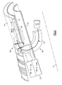
Figure 1 schematically illustrates agas turbine engine 20. Thegas turbine engine 20 is disclosed herein as a two-spool turbofan that generally incorporates aforward fan section 22, a highpressure compressor section 24, acombustor section 26, a highpressure turbine section 28, a lowpressure turbine section 30, an aft core driven fan section (CDFS) 32, anexhaust duct section 34 and anozzle section 36. Additional sections may include an augmentor section (not shown) among other systems or features such as a geared architecture and/or a third spool architecture. The sections are defined along a central longitudinal engine axis A. - The
engine 20 generally includes alow spool 38 and ahigh spool 40 which rotate about the engine central longitudinal axis A relative to anengine case structure 42 viaseveral bearing systems 44. It should be understood that various bearing systems at various locations may alternatively or additionally be provided. - The
forward fan section 22 and the lowpressure turbine section 30 are coupled by alow shaft 46 to define thelow spool 38. In the disclosed non-limiting embodiment, theforward fan section 22 includes two stages with aninlet guide vane 48, afirst fan stator 50A, afirst fan rotor 22A, asecond fan stator 50B and asecond fan rotor 22B. It should be understood that other fan stage architectures may alternatively or additionally be provided. - The high
pressure compressor section 24, thecombustor section 26 and the highpressure turbine section 28 are referred to herein as a reverse core as the highpressure turbine section 28 is arranged mechanically axially forward along the engine axis A of thecombustor section 26 while the highpressure compressor section 24 is arranged mechanically axially aft along the engine axis A of thecombustor section 26. The highpressure compressor section 24, the highpressure turbine section 28 and the aft core driven fan section (CDFS) 32 are coupled by ahigh shaft 52 to define thehigh spool 40. - The
engine case structure 42 generally includes anouter case structure 54, aninner case structure 56 and a thirdstream case structure 58 radially between theouter case structure 54 and theinner case structure 56. It should be understood that various structures individual or collectively within the engine may define thecase structures spools - The aft core driven fan section (CDFS) 32 is located generally within the
outer case structure 54 radially between thethird stream structure 58 and theinner case structure 56. The aft core driven fan section (CDFS) 32 is the axially aftmost rotary section of thehigh spool 40 and may be generally positioned along theexhaust duct section 34. - The aft core driven fan section (CDFS) 32 generally includes an aft
inlet guide vane 60, anaft fan rotor 62 and anaft fan stator 64. The aftinlet guide vane 60 and theaft fan stator 64 may at least partially support theinner case structure 56 relative to the thirdstream case structure 58. The aftinlet guide vane 60 also facilitates adjustment of the swirl into theaft fan rotor 62 without adverse effect on the highpressure compressor section 24 as the aft core driven fan section (CDFS) 32 is mechanically axially aftward thereof. That is, the aftinlet guide vane 60 may be readily adjusted without flow effect upon the highpressure compressor section 24 as the aftinlet guide vane 60 is mechanically aft thereof. - The
engine case structure 42 further includes a radial support structure referred to herein as a Fan Exit Guide Vane (FEGV)structure 66 located axially between theforward fan section 22 and the lowpressure turbine section 30. TheFEGV structure 66 is illustrated somewhat schematically, but may form at least partially hollow struts which integrate, for example, thecase structures spools FEGV structure 66 provides a forward radial support for theouter case structure 54 and theinner case structure 56 and the thirdstream case structure 58 as well as provide aturning flow path 68 from acore flow path 70 to a mixedflow path 72. - A third
stream flow path 74 is defined radially inward of themixed flow path 72 to asplit 76 then continues to thecore flow path 70 as well as to the aft core driven fan section (CDFS) 32 thence through athird stream exhaust 78 radially inward of themixed flow exhaust 80 in theexhaust duct section 34. - The
nozzle section 36 may include a third stream exhaust nozzle 82 (illustrated schematically) and the mixedflow exhaust nozzle 84. It should be understood that various variable, convergent/divergent, two-dimensional and three-dimensional nozzle systems may be utilized herewith. - Air which enters the
fan section 22 is divided between a mixed flow along the mixedflow path 72 and a third stream flow along the third stream flow path 74 (Figure 2 ). In this non-limiting embodiment, the mixedflow path 72 is arranged as an annulus just within the inner diameter (ID) of theouter case structure 54 and radially outward of the thirdstream flow path 74. That is, fan air primarily from the inner diameter of thefan section 22 is used to supercharge the highpressure compressor section 24 as the third stream flow from the thirdstream flow path 74. - The third stream flow from the third
stream flow path 74 is communicated to thesplit 76 thence aftward through the aft core driven fan section (CDFS) 32 as well as forward into thecore flow path 70 as reverse core flow. The reverse core flow is compressed by the highpressure compressor section 24, mixed and burned with fuel within thecombustor section 26, then expanded over the highpressure turbine section 28 and the lowpressure turbine section 30 to generate a relatively hot combustion gas core flow. Theturbines low spool 38 andhigh spool 40 in response to expansion of the hot combustion gas core flow in the reverse core flow arrangement. That is, the reverse core flow flows in a direction generally parallel to the axis A but opposite that of the mixed flow as well as the third stream flow upstream of thesplit 76 and downstream of the aft core driven fan section (CDFS) 32. - The
FEGV structure 66 reorients the relatively hot combustion gas core flow from thecombustor section 26 andturbines mixed flow path 72 downstream of the fan section 22 (Figure 2 ). That is, the mixed flow is "mixed" because it includes both the relatively hot combustion gas core flow and the relatively cool fan flow from the fan section 22 - in this non-limiting embodiment primarily from the OD of thefan section 22. TheFEGV structure 66 turns the combustion gas core flow essentially one hundred and eighty (180) degrees. TheFEGV structure 66 also provides for de-swirl thru flow of the relatively cool fan air which is divided into the mixed flow along the mixedflow path 72 and the third stream flow along the third stream flow path 74 (Figure 3 ). That is, theFEGV structure 66 turns the combustion gas core flow to join with the mixedflow path 72 which is arranged as a radially outermost annulus just within the inner diameter (ID) of theouter case structure 54 and radially outward of the third stream flow path -74. - The third stream flow from the
third stream path 74 is advantageously arranged through an annulus radially within themixed flow path 72 which is essentially the inner diameter (ID) of thefan section 22 and is relatively lower in pressure than the OD of thefan section 22 which sources themixed flow path 72. - The combustion gas core flow is mixed with the fan OD flow to quench the temperature of the combustion gas core from downstream of the
turbines third stream exhaust 78 is radially inboard of the mixedflow exhaust 80. Thethird stream exhaust 78 is radially closer to the engine axis A to essentially sheath the reverse flow core. - The aft core driven fan section (CDFS) 32 selectively lowers the inlet temperature to the high
pressure compressor section 24 as well as increases the pressure ratio of the third stream flow to facilitate a relatively smaller reverse flow core. The power demanded by the aft core driven fan section (CDFS) 32 and the thrust contribution of the aft core driven fan section (CDFS) 32 may be selectively controlled by a combination of the aftinlet guide vane 60 and a variable area throat provided by the thirdstream exhaust nozzle 82. - For high power, the
combustor section 26 fuel flow is increased, the aftinlet guide vane 60 is closed, and the thirdstream exhaust nozzle 82 is closed to minimize the aft core driven fan section (CDFS) 32 air flow and maximize the pressure ratio of the aft core driven fan section (CDFS) 32. This is the high specific thrust mode. One benefit thereof is the work on thehigh spool 40 is increased and the highpressure turbine section 28 exit temperature (T4.5) is lower compared to an engine without the aft core driven fan section (CDFS) 32. - For cruise power, the
combustor section 26 fuel flow is decreased, theaft inlet guide 60 is opened, and the thirdstream exhaust nozzle 82 throat area is opened to reduce the power demand of the aft core driven fan section (CDFS) 32 such that thehigh spool 40 runs relatively faster for a given fuel flow rate to thecombustor section 26. Running thehigh spool 40 faster increases the engine overall pressure ratio which is more efficient. Further, increased flow at a lower pressure ratio through the thirdstream exhaust nozzle 82 is relatively more efficient as a propulsor at cruise power. - With reference to
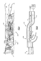
Figure 4 , anothergas turbine engine 20A with a reverse flow core is generally as described above but with a flow interchange 100 (Figure 5 ) downstream of theFEGV structure 66A. Theflow interchange 100 may be defined by theFEGV structure 66A or may be located downstream thereof as separate duct sections formed by theengine case structure 42. - The
FEGV structure 66A turns the combustion gas core flow to initially join with fan flow primarily from the inner diameter (ID) of the fan section 22 (Figure 6 ) to provide the mixed flow. The flow interchange 100 (Figure 5 ) then crosses the mixed flow of the combustion gas core flow and the ID fan air with the OD fan air which becomes the third stream flow such that themixed flow exhaust 80 is radially outboard of thethird stream exhaust 78 as described above. The radially outermostmixed flow exhaust 80 is arranged as an annulus just within the inner diameter (ID) of theouter case structure 54 and radially outward of thethird stream exhaust 78. That is, the relatively higher pressure ratio fan air from the outer diameter (OD) of the fan section 22 - as compared to the relatively lower pressure ratio fan air from the inner diameter (ID) of the fan section 22 (Figure 1 ) - is used as third stream flow to supercharge the highpressure compressor section 24 through theflow interchange 100. - It should be understood that relative positional terms such as "forward," "aft," "upper," "lower," "above," "below," and the like are with reference to the engine but should not be considered otherwise limiting.
- It should be understood that like reference numerals identify corresponding or similar elements throughout the several drawings. It should also be understood that although a particular component arrangement is disclosed in the illustrated embodiment, other arrangements will benefit herefrom.
- Although particular step sequences are shown, described, and claimed, it should be understood that steps may be performed in any order, separated or combined unless otherwise indicated and will still benefit from the present disclosure.
- The foregoing description is exemplary rather than defined by the limitations within. Various non-limiting embodiments are disclosed herein, however, one of ordinary skill in the art would recognize that various modifications and variations in light of the above teachings will fall within the scope of the appended claims. It is therefore to be understood that within the scope of the appended claims, the disclosure may be practiced other than as specifically described. For that reason the appended claims should be studied to determine true scope and content.
Claims (15)
- A gas turbine engine (20) comprising:a low spool (38) along an engine axis (A) with a forward fan section (22) and a low pressure turbine section (30); anda high spool (40) along said engine axis (A) with a high pressure turbine section (28) and an aft core driven fan section (CDFS) (32), said aft core driven fan section (CDFS) (32) axially aft of said high pressure turbine section (28) along said engine axis (A).
- The gas turbine engine as recited in claim 1, wherein said high spool (40) includes a high pressure compressor section (24), and further optionally comprising a combustor (26) section axially between said high pressure turbine section (28) and said high pressure compressor section (24), said high pressure turbine section (28) optionally being axially forward of said high pressure compressor section (24).
- The gas turbine engine as recited in claim 1 or 2, wherein said forward fan section (24) includes a multiple of stages.
- The gas turbine engine as recited in any preceding claim, wherein said low pressure turbine section (30) is axially aft of said forward fan section (22).
- The gas turbine engine as recited in any preceding claim, further comprising a Fan Exit Guide Vane (FEGV) structure (66; 66A) located axially between said forward fan section (22) and said low pressure turbine section (30).
- The gas turbine engine as recited in claim 5, wherein said Fan Exit Guide Vane (FEGV) structure (66) mixes a combustion gas core flow (70) from said high pressure turbine section (28) with a fan air from an outer diameter of said forward fan section (22).
- The gas turbine engine as recited in claim 6, further comprising a third stream flow (74) primarily sourced from an inner diameter of said forward fan section (22), said third stream flow (74) optionally being split between said aft core driven fan section (CDFS) (32) and a or said high pressure compressor (24) axially forward of said aft core driven fan section (CDFS) (32).
- The gas turbine engine as recited in claim 5 or 6, wherein said Fan Exit Guide Vane (FEGV) structure (66A) mixes a combustion gas core flow (70) from said high pressure turbine section (28) with a fan air from an inner diameter of said forward fan section (22).
- The gas turbine engine as recited in claim 8, further comprising a third stream flow (74) primarily sourced from an outer diameter of said forward fan section (22), and wherein, optionally, said third stream flow (74) is split between said aft core driven fan section (CDFS) (32) and a or said high pressure compressor (24) axially forward of said aft core driven fan section (CDFS) (32).
- The gas turbine engine as recited in claim 9, wherein fan air from said inner diameter of said forward fan section (22) crosses fan air from said outer diameter of said forward fan section (22), optionally aft of said Fan Exit Guide Vane (FEGV) structure (66A).
- The gas turbine engine as recited in any preceding claim, wherein said aft core driven fan section (CDFS) (32) is radially between an inner case structure (56) and a third stream case structure (58) which form a third stream exhaust duct (78), said third stream exhaust duct (78) optionally being radially inward of a mixed flow exhaust duct (80).
- A gas turbine engine (20) comprising:a forward fan section (22) in communication with a third stream exhaust duct (78) and a mixed flow exhaust duct (80); andan aft core driven fan section (CDFS) (32) axially aft of said forward fan section (22), said aft core driven fan section (CDFS) (32) in communication with said third stream exhaust duct (78), wherein, optionally, said aft core driven fan section (CDFS) (32) includes an inlet guide vane (60) radially between an inner case structure (56) and a third stream case structure (58) which forms said third stream exhaust duct (78), and/or optionally wherein said mixed flow exhaust duct (78) is radially outward of said third stream exhaust duct (80).
- A method of operating a gas turbine engine comprising:controlling an aft inlet guide vane (60) of an aft core driven fan section (CDFS) (32); andcontrolling a variable area throat of a third stream exhaust nozzle (78) downstream of the aft core driven fan section (32).
- A method as recited in claim 13, further comprising:closing the aft inlet guide vane (60); andclosing the third stream exhaust nozzle (78) to reduce the aft core driven fan section (CDFS) air flow and increase a pressure ratio of the aft core driven fan section (32) (CDFS) for a high power condition.
- A method as recited in claim 13 or 14, further comprising:opening the aft inlet guide vane (60); andopening the third stream exhaust nozzle (78) to increase the aft core driven fan section (CDFS) air flow and decrease a pressure ratio of the aft core driven fan section (CDFS) (32) for a cruise power condition.
Applications Claiming Priority (1)
| Application Number | Priority Date | Filing Date | Title |
|---|---|---|---|
| US13/190,595 US8516789B2 (en) | 2011-07-26 | 2011-07-26 | Gas turbine engine with aft core driven fan section |
Publications (3)
| Publication Number | Publication Date |
|---|---|
| EP2551485A2 true EP2551485A2 (en) | 2013-01-30 |
| EP2551485A3 EP2551485A3 (en) | 2017-05-17 |
| EP2551485B1 EP2551485B1 (en) | 2019-01-09 |
Family
ID=46551435
Family Applications (1)
| Application Number | Title | Priority Date | Filing Date |
|---|---|---|---|
| EP12177794.0A Active EP2551485B1 (en) | 2011-07-26 | 2012-07-25 | Gas turbine engine with aft core driven fan section |
Country Status (2)
| Country | Link |
|---|---|
| US (1) | US8516789B2 (en) |
| EP (1) | EP2551485B1 (en) |
Cited By (1)
| Publication number | Priority date | Publication date | Assignee | Title |
|---|---|---|---|---|
| EP3296542A1 (en) * | 2016-09-19 | 2018-03-21 | United Technologies Corporation | Split compressor turbine engine |
Families Citing this family (29)
| Publication number | Priority date | Publication date | Assignee | Title |
|---|---|---|---|---|
| US9239004B2 (en) | 2012-03-27 | 2016-01-19 | United Technologies Corporation | Reverse core gear turbofan |
| US9140212B2 (en) * | 2012-06-25 | 2015-09-22 | United Technologies Corporation | Gas turbine engine with reverse-flow core having a bypass flow splitter |
| US10202941B2 (en) * | 2012-11-12 | 2019-02-12 | United Technologies Corporation | Reverse core turbine engine mounted above aircraft wing |
| US9726112B2 (en) * | 2013-03-07 | 2017-08-08 | United Technologies Corporation | Reverse flow gas turbine engine airflow bypass |
| US9845159B2 (en) | 2013-03-07 | 2017-12-19 | United Technologies Corporation | Conjoined reverse core flow engine arrangement |
| US9574520B2 (en) | 2013-03-07 | 2017-02-21 | United Technologies Corporation | Reverse core engine thrust reverser for under wing |
| US9897040B2 (en) | 2013-03-07 | 2018-02-20 | United Technologies Corporation | Rear mounted reverse core engine thrust reverser |
| US9523329B2 (en) * | 2013-03-15 | 2016-12-20 | United Technologies Corporation | Gas turbine engine with stream diverter |
| US10072584B2 (en) | 2013-12-03 | 2018-09-11 | United Technologies Corporation | Multi-bypass stream gas turbine engine with enlarged bypass flow area |
| EP3080424B1 (en) | 2013-12-13 | 2022-05-04 | Raytheon Technologies Corporation | Architecture for an axially compact, high performance propulsion system |
| US10711631B2 (en) * | 2014-12-24 | 2020-07-14 | Raytheon Technologies Corporation | Turbine engine with guide vanes forward of its fan blades |
| US10794273B2 (en) | 2015-07-01 | 2020-10-06 | Raytheon Technologies Corporation | Advanced distributed engine architecture-design alternative |
| US11415063B2 (en) | 2016-09-15 | 2022-08-16 | Pratt & Whitney Canada Corp. | Reverse-flow gas turbine engine |
| US10883424B2 (en) | 2016-07-19 | 2021-01-05 | Pratt & Whitney Canada Corp. | Multi-spool gas turbine engine architecture |
| US10287024B2 (en) | 2016-08-04 | 2019-05-14 | United Technologies Corporation | Direct drive aft fan engine |
| US10352274B2 (en) | 2016-08-18 | 2019-07-16 | United Technologies Corporation | Direct drive aft fan engine |
| US10393067B2 (en) * | 2016-08-25 | 2019-08-27 | United Technologies Corporation | Gas turbine engine with cold turbine and multiple core flowpaths |
| US11035293B2 (en) | 2016-09-15 | 2021-06-15 | Pratt & Whitney Canada Corp. | Reverse flow gas turbine engine with offset RGB |
| US10465611B2 (en) | 2016-09-15 | 2019-11-05 | Pratt & Whitney Canada Corp. | Reverse flow multi-spool gas turbine engine with aft-end accessory gearbox drivingly connected to both high pressure spool and low pressure spool |
| US10815899B2 (en) | 2016-11-15 | 2020-10-27 | Pratt & Whitney Canada Corp. | Gas turbine engine accessories arrangement |
| US10823056B2 (en) | 2016-12-07 | 2020-11-03 | Raytheon Technologies Corporation | Boundary layer excitation aft fan gas turbine engine |
| US10738709B2 (en) | 2017-02-09 | 2020-08-11 | Pratt & Whitney Canada Corp. | Multi-spool gas turbine engine |
| US10808624B2 (en) | 2017-02-09 | 2020-10-20 | Pratt & Whitney Canada Corp. | Turbine rotor with low over-speed requirements |
| US10215052B2 (en) | 2017-03-14 | 2019-02-26 | Pratt & Whitney Canada Corp. | Inter-shaft bearing arrangement |
| US10746188B2 (en) | 2017-03-14 | 2020-08-18 | Pratt & Whitney Canada Corp. | Inter-shaft bearing connected to a compressor boost system |
| CN108252823A (en) * | 2017-12-27 | 2018-07-06 | 中国航发四川燃气涡轮研究院 | A kind of outer culvert structure for adapting to become the low adjustable support plate of loss of flow angle |
| CN110821677A (en) | 2018-08-08 | 2020-02-21 | 普拉特 - 惠特尼加拿大公司 | Multi-engine system and method |
| CN109684703B (en) * | 2018-12-17 | 2019-08-23 | 中国航发沈阳发动机研究所 | A kind of aeroengine modeling method with CDFS structure |
| US11781506B2 (en) | 2020-06-03 | 2023-10-10 | Rtx Corporation | Splitter and guide vane arrangement for gas turbine engines |
Family Cites Families (15)
| Publication number | Priority date | Publication date | Assignee | Title |
|---|---|---|---|---|
| US2504181A (en) | 1950-04-18 | Double compound independent rotor | ||
| US2454738A (en) | 1944-01-31 | 1948-11-23 | Power Jets Res And Development | Internal-combustion turbine power plant |
| US2546420A (en) | 1944-03-28 | 1951-03-27 | Power Jets Res & Dev Ltd | Internal-combustion turbine power plant |
| US2704434A (en) | 1950-03-20 | 1955-03-22 | Heinz E Schmitt | High pressure ratio gas turbine of the dual set type |
| US3131536A (en) * | 1961-06-30 | 1964-05-05 | Bristol Siddeley Engines Ltd | Jet propulsion power plants of the combustion turbine type |
| US3677012A (en) * | 1962-05-31 | 1972-07-18 | Gen Electric | Composite cycle turbomachinery |
| US3589132A (en) | 1969-06-04 | 1971-06-29 | Garrett Corp | Gas turbine engine |
| GB1370887A (en) | 1970-09-26 | 1974-10-16 | Secr Defence | Aircraft and gas turbine engines therefor |
| US4055949A (en) * | 1973-05-08 | 1977-11-01 | Societe Nationale D'etude Et De Construction De Moteurs D'aviation | Multiflow gas turbine power plant |
| FR2606081A1 (en) | 1986-10-29 | 1988-05-06 | Snecma | PROPULSION ENGINE WITH CONTRAROTATING WORKING TURBINES |
| US6209311B1 (en) * | 1998-04-13 | 2001-04-03 | Nikkiso Company, Ltd. | Turbofan engine including fans with reduced speed |
| FR2858999B1 (en) * | 2003-08-18 | 2005-11-11 | Snecma Moteurs | TURBOMACHINE FOR AIRCRAFT WITH REDUCED NOISE EMISSIONS |
| US7134271B2 (en) * | 2004-11-05 | 2006-11-14 | General Electric Company | Thrust vectoring aft FLADE engine |
| US20070000232A1 (en) * | 2005-06-29 | 2007-01-04 | General Electric Company | Gas turbine engine and method of operating same |
| US8176725B2 (en) * | 2009-09-09 | 2012-05-15 | United Technologies Corporation | Reversed-flow core for a turbofan with a fan drive gear system |
-
2011
- 2011-07-26 US US13/190,595 patent/US8516789B2/en not_active Expired - Fee Related
-
2012
- 2012-07-25 EP EP12177794.0A patent/EP2551485B1/en active Active
Non-Patent Citations (1)
| Title |
|---|
| None |
Cited By (2)
| Publication number | Priority date | Publication date | Assignee | Title |
|---|---|---|---|---|
| EP3296542A1 (en) * | 2016-09-19 | 2018-03-21 | United Technologies Corporation | Split compressor turbine engine |
| US10385774B2 (en) | 2016-09-19 | 2019-08-20 | United Technologies Corporation | Split compressor turbine engine |
Also Published As
| Publication number | Publication date |
|---|---|
| EP2551485B1 (en) | 2019-01-09 |
| EP2551485A3 (en) | 2017-05-17 |
| US20130025286A1 (en) | 2013-01-31 |
| US8516789B2 (en) | 2013-08-27 |
Similar Documents
| Publication | Publication Date | Title |
|---|---|---|
| EP2551485B1 (en) | Gas turbine engine with aft core driven fan section | |
| US9341121B2 (en) | Gas turbine engine with intercooling turbine section and intercooling turbine section bypass | |
| US9057328B2 (en) | Gas turbine engine with intercooling turbine section | |
| US9016041B2 (en) | Variable-cycle gas turbine engine with front and aft FLADE stages | |
| US9140188B2 (en) | Gas turbine engine with intercooling turbine section | |
| US20110167784A1 (en) | Method of operating a convertible fan engine | |
| US20110167792A1 (en) | Adaptive engine | |
| US8935923B2 (en) | Gas turbine engine with intercooling turbine section and intercooling turbine section bypass | |
| US20190316544A1 (en) | Variable area exhaust mixer for a gas turbine engine | |
| US10378478B2 (en) | Flow path routing within a gas turbine engine | |
| EP3904641A1 (en) | Variable area turbine vane row assembly | |
| US11066989B2 (en) | Gas turbine engine architecture with nested concentric combustor | |
| US10704415B2 (en) | Gas turbine engine with low fan noise | |
| US9752585B2 (en) | Gas turbine engine architecture with intercooled twin centrifugal compressor | |
| US20140165575A1 (en) | Nozzle section for a gas turbine engine |
Legal Events
| Date | Code | Title | Description |
|---|---|---|---|
| PUAI | Public reference made under article 153(3) epc to a published international application that has entered the european phase |
Free format text: ORIGINAL CODE: 0009012 |
|
| AK | Designated contracting states |
Kind code of ref document: A2 Designated state(s): AL AT BE BG CH CY CZ DE DK EE ES FI FR GB GR HR HU IE IS IT LI LT LU LV MC MK MT NL NO PL PT RO RS SE SI SK SM TR |
|
| AX | Request for extension of the european patent |
Extension state: BA ME |
|
| RAP1 | Party data changed (applicant data changed or rights of an application transferred) |
Owner name: UNITED TECHNOLOGIES CORPORATION |
|
| PUAL | Search report despatched |
Free format text: ORIGINAL CODE: 0009013 |
|
| AK | Designated contracting states |
Kind code of ref document: A3 Designated state(s): AL AT BE BG CH CY CZ DE DK EE ES FI FR GB GR HR HU IE IS IT LI LT LU LV MC MK MT NL NO PL PT RO RS SE SI SK SM TR |
|
| AX | Request for extension of the european patent |
Extension state: BA ME |
|
| RIC1 | Information provided on ipc code assigned before grant |
Ipc: F02C 3/14 20060101ALI20170411BHEP Ipc: F02K 3/075 20060101ALI20170411BHEP Ipc: F02C 3/13 20060101AFI20170411BHEP Ipc: F02K 3/077 20060101ALI20170411BHEP Ipc: F02K 3/065 20060101ALI20170411BHEP |
|
| STAA | Information on the status of an ep patent application or granted ep patent |
Free format text: STATUS: REQUEST FOR EXAMINATION WAS MADE |
|
| 17P | Request for examination filed |
Effective date: 20171114 |
|
| RBV | Designated contracting states (corrected) |
Designated state(s): AL AT BE BG CH CY CZ DE DK EE ES FI FR GB GR HR HU IE IS IT LI LT LU LV MC MK MT NL NO PL PT RO RS SE SI SK SM TR |
|
| RIC1 | Information provided on ipc code assigned before grant |
Ipc: F02C 3/14 20060101ALI20171130BHEP Ipc: F02K 3/075 20060101ALI20171130BHEP Ipc: F02C 3/13 20060101AFI20171130BHEP Ipc: F02K 3/077 20060101ALI20171130BHEP Ipc: F02K 3/065 20060101ALI20171130BHEP |
|
| GRAP | Despatch of communication of intention to grant a patent |
Free format text: ORIGINAL CODE: EPIDOSNIGR1 |
|
| STAA | Information on the status of an ep patent application or granted ep patent |
Free format text: STATUS: GRANT OF PATENT IS INTENDED |
|
| INTG | Intention to grant announced |
Effective date: 20180425 |
|
| GRAS | Grant fee paid |
Free format text: ORIGINAL CODE: EPIDOSNIGR3 |
|
| GRAA | (expected) grant |
Free format text: ORIGINAL CODE: 0009210 |
|
| STAA | Information on the status of an ep patent application or granted ep patent |
Free format text: STATUS: THE PATENT HAS BEEN GRANTED |
|
| AK | Designated contracting states |
Kind code of ref document: B1 Designated state(s): AL AT BE BG CH CY CZ DE DK EE ES FI FR GB GR HR HU IE IS IT LI LT LU LV MC MK MT NL NO PL PT RO RS SE SI SK SM TR |
|
| REG | Reference to a national code |
Ref country code: GB Ref legal event code: FG4D |
|
| REG | Reference to a national code |
Ref country code: CH Ref legal event code: EP Ref country code: AT Ref legal event code: REF Ref document number: 1087583 Country of ref document: AT Kind code of ref document: T Effective date: 20190115 |
|
| REG | Reference to a national code |
Ref country code: DE Ref legal event code: R096 Ref document number: 602012055622 Country of ref document: DE |
|
| REG | Reference to a national code |
Ref country code: IE Ref legal event code: FG4D |
|
| REG | Reference to a national code |
Ref country code: NL Ref legal event code: MP Effective date: 20190109 |
|
| REG | Reference to a national code |
Ref country code: LT Ref legal event code: MG4D |
|
| PG25 | Lapsed in a contracting state [announced via postgrant information from national office to epo] |
Ref country code: NL Free format text: LAPSE BECAUSE OF FAILURE TO SUBMIT A TRANSLATION OF THE DESCRIPTION OR TO PAY THE FEE WITHIN THE PRESCRIBED TIME-LIMIT Effective date: 20190109 |
|
| REG | Reference to a national code |
Ref country code: AT Ref legal event code: MK05 Ref document number: 1087583 Country of ref document: AT Kind code of ref document: T Effective date: 20190109 |
|
| PG25 | Lapsed in a contracting state [announced via postgrant information from national office to epo] |
Ref country code: LT Free format text: LAPSE BECAUSE OF FAILURE TO SUBMIT A TRANSLATION OF THE DESCRIPTION OR TO PAY THE FEE WITHIN THE PRESCRIBED TIME-LIMIT Effective date: 20190109 Ref country code: PL Free format text: LAPSE BECAUSE OF FAILURE TO SUBMIT A TRANSLATION OF THE DESCRIPTION OR TO PAY THE FEE WITHIN THE PRESCRIBED TIME-LIMIT Effective date: 20190109 Ref country code: SE Free format text: LAPSE BECAUSE OF FAILURE TO SUBMIT A TRANSLATION OF THE DESCRIPTION OR TO PAY THE FEE WITHIN THE PRESCRIBED TIME-LIMIT Effective date: 20190109 Ref country code: NO Free format text: LAPSE BECAUSE OF FAILURE TO SUBMIT A TRANSLATION OF THE DESCRIPTION OR TO PAY THE FEE WITHIN THE PRESCRIBED TIME-LIMIT Effective date: 20190409 Ref country code: ES Free format text: LAPSE BECAUSE OF FAILURE TO SUBMIT A TRANSLATION OF THE DESCRIPTION OR TO PAY THE FEE WITHIN THE PRESCRIBED TIME-LIMIT Effective date: 20190109 Ref country code: PT Free format text: LAPSE BECAUSE OF FAILURE TO SUBMIT A TRANSLATION OF THE DESCRIPTION OR TO PAY THE FEE WITHIN THE PRESCRIBED TIME-LIMIT Effective date: 20190509 Ref country code: FI Free format text: LAPSE BECAUSE OF FAILURE TO SUBMIT A TRANSLATION OF THE DESCRIPTION OR TO PAY THE FEE WITHIN THE PRESCRIBED TIME-LIMIT Effective date: 20190109 |
|
| PG25 | Lapsed in a contracting state [announced via postgrant information from national office to epo] |
Ref country code: GR Free format text: LAPSE BECAUSE OF FAILURE TO SUBMIT A TRANSLATION OF THE DESCRIPTION OR TO PAY THE FEE WITHIN THE PRESCRIBED TIME-LIMIT Effective date: 20190410 Ref country code: IS Free format text: LAPSE BECAUSE OF FAILURE TO SUBMIT A TRANSLATION OF THE DESCRIPTION OR TO PAY THE FEE WITHIN THE PRESCRIBED TIME-LIMIT Effective date: 20190509 Ref country code: RS Free format text: LAPSE BECAUSE OF FAILURE TO SUBMIT A TRANSLATION OF THE DESCRIPTION OR TO PAY THE FEE WITHIN THE PRESCRIBED TIME-LIMIT Effective date: 20190109 Ref country code: BG Free format text: LAPSE BECAUSE OF FAILURE TO SUBMIT A TRANSLATION OF THE DESCRIPTION OR TO PAY THE FEE WITHIN THE PRESCRIBED TIME-LIMIT Effective date: 20190409 Ref country code: LV Free format text: LAPSE BECAUSE OF FAILURE TO SUBMIT A TRANSLATION OF THE DESCRIPTION OR TO PAY THE FEE WITHIN THE PRESCRIBED TIME-LIMIT Effective date: 20190109 Ref country code: HR Free format text: LAPSE BECAUSE OF FAILURE TO SUBMIT A TRANSLATION OF THE DESCRIPTION OR TO PAY THE FEE WITHIN THE PRESCRIBED TIME-LIMIT Effective date: 20190109 |
|
| REG | Reference to a national code |
Ref country code: DE Ref legal event code: R097 Ref document number: 602012055622 Country of ref document: DE |
|
| PG25 | Lapsed in a contracting state [announced via postgrant information from national office to epo] |
Ref country code: AL Free format text: LAPSE BECAUSE OF FAILURE TO SUBMIT A TRANSLATION OF THE DESCRIPTION OR TO PAY THE FEE WITHIN THE PRESCRIBED TIME-LIMIT Effective date: 20190109 Ref country code: DK Free format text: LAPSE BECAUSE OF FAILURE TO SUBMIT A TRANSLATION OF THE DESCRIPTION OR TO PAY THE FEE WITHIN THE PRESCRIBED TIME-LIMIT Effective date: 20190109 Ref country code: SK Free format text: LAPSE BECAUSE OF FAILURE TO SUBMIT A TRANSLATION OF THE DESCRIPTION OR TO PAY THE FEE WITHIN THE PRESCRIBED TIME-LIMIT Effective date: 20190109 Ref country code: EE Free format text: LAPSE BECAUSE OF FAILURE TO SUBMIT A TRANSLATION OF THE DESCRIPTION OR TO PAY THE FEE WITHIN THE PRESCRIBED TIME-LIMIT Effective date: 20190109 Ref country code: IT Free format text: LAPSE BECAUSE OF FAILURE TO SUBMIT A TRANSLATION OF THE DESCRIPTION OR TO PAY THE FEE WITHIN THE PRESCRIBED TIME-LIMIT Effective date: 20190109 Ref country code: CZ Free format text: LAPSE BECAUSE OF FAILURE TO SUBMIT A TRANSLATION OF THE DESCRIPTION OR TO PAY THE FEE WITHIN THE PRESCRIBED TIME-LIMIT Effective date: 20190109 Ref country code: AT Free format text: LAPSE BECAUSE OF FAILURE TO SUBMIT A TRANSLATION OF THE DESCRIPTION OR TO PAY THE FEE WITHIN THE PRESCRIBED TIME-LIMIT Effective date: 20190109 Ref country code: RO Free format text: LAPSE BECAUSE OF FAILURE TO SUBMIT A TRANSLATION OF THE DESCRIPTION OR TO PAY THE FEE WITHIN THE PRESCRIBED TIME-LIMIT Effective date: 20190109 |
|
| PLBE | No opposition filed within time limit |
Free format text: ORIGINAL CODE: 0009261 |
|
| STAA | Information on the status of an ep patent application or granted ep patent |
Free format text: STATUS: NO OPPOSITION FILED WITHIN TIME LIMIT |
|
| PG25 | Lapsed in a contracting state [announced via postgrant information from national office to epo] |
Ref country code: SM Free format text: LAPSE BECAUSE OF FAILURE TO SUBMIT A TRANSLATION OF THE DESCRIPTION OR TO PAY THE FEE WITHIN THE PRESCRIBED TIME-LIMIT Effective date: 20190109 |
|
| 26N | No opposition filed |
Effective date: 20191010 |
|
| PG25 | Lapsed in a contracting state [announced via postgrant information from national office to epo] |
Ref country code: MC Free format text: LAPSE BECAUSE OF FAILURE TO SUBMIT A TRANSLATION OF THE DESCRIPTION OR TO PAY THE FEE WITHIN THE PRESCRIBED TIME-LIMIT Effective date: 20190109 Ref country code: SI Free format text: LAPSE BECAUSE OF FAILURE TO SUBMIT A TRANSLATION OF THE DESCRIPTION OR TO PAY THE FEE WITHIN THE PRESCRIBED TIME-LIMIT Effective date: 20190109 |
|
| REG | Reference to a national code |
Ref country code: CH Ref legal event code: PL |
|
| PG25 | Lapsed in a contracting state [announced via postgrant information from national office to epo] |
Ref country code: TR Free format text: LAPSE BECAUSE OF FAILURE TO SUBMIT A TRANSLATION OF THE DESCRIPTION OR TO PAY THE FEE WITHIN THE PRESCRIBED TIME-LIMIT Effective date: 20190109 |
|
| REG | Reference to a national code |
Ref country code: BE Ref legal event code: MM Effective date: 20190731 |
|
| PG25 | Lapsed in a contracting state [announced via postgrant information from national office to epo] |
Ref country code: LI Free format text: LAPSE BECAUSE OF NON-PAYMENT OF DUE FEES Effective date: 20190731 Ref country code: CH Free format text: LAPSE BECAUSE OF NON-PAYMENT OF DUE FEES Effective date: 20190731 Ref country code: LU Free format text: LAPSE BECAUSE OF NON-PAYMENT OF DUE FEES Effective date: 20190725 Ref country code: BE Free format text: LAPSE BECAUSE OF NON-PAYMENT OF DUE FEES Effective date: 20190731 |
|
| PG25 | Lapsed in a contracting state [announced via postgrant information from national office to epo] |
Ref country code: FR Free format text: LAPSE BECAUSE OF NON-PAYMENT OF DUE FEES Effective date: 20190731 |
|
| PG25 | Lapsed in a contracting state [announced via postgrant information from national office to epo] |
Ref country code: IE Free format text: LAPSE BECAUSE OF NON-PAYMENT OF DUE FEES Effective date: 20190725 |
|
| PG25 | Lapsed in a contracting state [announced via postgrant information from national office to epo] |
Ref country code: CY Free format text: LAPSE BECAUSE OF FAILURE TO SUBMIT A TRANSLATION OF THE DESCRIPTION OR TO PAY THE FEE WITHIN THE PRESCRIBED TIME-LIMIT Effective date: 20190109 |
|
| PG25 | Lapsed in a contracting state [announced via postgrant information from national office to epo] |
Ref country code: HU Free format text: LAPSE BECAUSE OF FAILURE TO SUBMIT A TRANSLATION OF THE DESCRIPTION OR TO PAY THE FEE WITHIN THE PRESCRIBED TIME-LIMIT; INVALID AB INITIO Effective date: 20120725 Ref country code: MT Free format text: LAPSE BECAUSE OF FAILURE TO SUBMIT A TRANSLATION OF THE DESCRIPTION OR TO PAY THE FEE WITHIN THE PRESCRIBED TIME-LIMIT Effective date: 20190109 |
|
| PG25 | Lapsed in a contracting state [announced via postgrant information from national office to epo] |
Ref country code: MK Free format text: LAPSE BECAUSE OF FAILURE TO SUBMIT A TRANSLATION OF THE DESCRIPTION OR TO PAY THE FEE WITHIN THE PRESCRIBED TIME-LIMIT Effective date: 20190109 |
|
| REG | Reference to a national code |
Ref country code: DE Ref legal event code: R081 Ref document number: 602012055622 Country of ref document: DE Owner name: RAYTHEON TECHNOLOGIES CORPORATION (N.D.GES.D.S, US Free format text: FORMER OWNER: UNITED TECHNOLOGIES CORPORATION, FARMINGTON, CONN., US |
|
| P01 | Opt-out of the competence of the unified patent court (upc) registered |
Effective date: 20230520 |
|
| PGFP | Annual fee paid to national office [announced via postgrant information from national office to epo] |
Ref country code: DE Payment date: 20230620 Year of fee payment: 12 |
|
| PGFP | Annual fee paid to national office [announced via postgrant information from national office to epo] |
Ref country code: GB Payment date: 20240620 Year of fee payment: 13 |