EP2551474A2 - System and method for supporting a shaft inside a turbine - Google Patents
System and method for supporting a shaft inside a turbine Download PDFInfo
- Publication number
- EP2551474A2 EP2551474A2 EP12178223A EP12178223A EP2551474A2 EP 2551474 A2 EP2551474 A2 EP 2551474A2 EP 12178223 A EP12178223 A EP 12178223A EP 12178223 A EP12178223 A EP 12178223A EP 2551474 A2 EP2551474 A2 EP 2551474A2
- Authority
- EP
- European Patent Office
- Prior art keywords
- support member
- shaft
- counterweight
- turbine
- fulcrum
- Prior art date
- Legal status (The legal status is an assumption and is not a legal conclusion. Google has not performed a legal analysis and makes no representation as to the accuracy of the status listed.)
- Granted
Links
Images


Classifications
-
- F—MECHANICAL ENGINEERING; LIGHTING; HEATING; WEAPONS; BLASTING
- F01—MACHINES OR ENGINES IN GENERAL; ENGINE PLANTS IN GENERAL; STEAM ENGINES
- F01D—NON-POSITIVE DISPLACEMENT MACHINES OR ENGINES, e.g. STEAM TURBINES
- F01D25/00—Component parts, details, or accessories, not provided for in, or of interest apart from, other groups
- F01D25/28—Supporting or mounting arrangements, e.g. for turbine casing
- F01D25/285—Temporary support structures, e.g. for testing, assembling, installing, repairing; Assembly methods using such structures
-
- F—MECHANICAL ENGINEERING; LIGHTING; HEATING; WEAPONS; BLASTING
- F05—INDEXING SCHEMES RELATING TO ENGINES OR PUMPS IN VARIOUS SUBCLASSES OF CLASSES F01-F04
- F05D—INDEXING SCHEME FOR ASPECTS RELATING TO NON-POSITIVE-DISPLACEMENT MACHINES OR ENGINES, GAS-TURBINES OR JET-PROPULSION PLANTS
- F05D2230/00—Manufacture
- F05D2230/60—Assembly methods
- F05D2230/68—Assembly methods using auxiliary equipment for lifting or holding
-
- F—MECHANICAL ENGINEERING; LIGHTING; HEATING; WEAPONS; BLASTING
- F05—INDEXING SCHEMES RELATING TO ENGINES OR PUMPS IN VARIOUS SUBCLASSES OF CLASSES F01-F04
- F05D—INDEXING SCHEME FOR ASPECTS RELATING TO NON-POSITIVE-DISPLACEMENT MACHINES OR ENGINES, GAS-TURBINES OR JET-PROPULSION PLANTS
- F05D2230/00—Manufacture
- F05D2230/72—Maintenance
-
- F—MECHANICAL ENGINEERING; LIGHTING; HEATING; WEAPONS; BLASTING
- F05—INDEXING SCHEMES RELATING TO ENGINES OR PUMPS IN VARIOUS SUBCLASSES OF CLASSES F01-F04
- F05D—INDEXING SCHEME FOR ASPECTS RELATING TO NON-POSITIVE-DISPLACEMENT MACHINES OR ENGINES, GAS-TURBINES OR JET-PROPULSION PLANTS
- F05D2230/00—Manufacture
- F05D2230/80—Repairing, retrofitting or upgrading methods
-
- F—MECHANICAL ENGINEERING; LIGHTING; HEATING; WEAPONS; BLASTING
- F05—INDEXING SCHEMES RELATING TO ENGINES OR PUMPS IN VARIOUS SUBCLASSES OF CLASSES F01-F04
- F05D—INDEXING SCHEME FOR ASPECTS RELATING TO NON-POSITIVE-DISPLACEMENT MACHINES OR ENGINES, GAS-TURBINES OR JET-PROPULSION PLANTS
- F05D2240/00—Components
- F05D2240/60—Shafts
Definitions
- the present invention generally involves a system and method for supporting a shaft inside a turbine.
- the system and method may be used to install and/or remove the shaft from the turbine during maintenance and repairs.
- Turbines are known in the art for extracting energy from a fluid and converting the extracted energy into work.
- a typical turbine includes alternating stages of stationary nozzles attached to an outer casing and rotating blades attached to a rotor.
- a working fluid such as steam, air, or combustion gases
- the stationary nozzles redirect and accelerate the working fluid onto the subsequent stage of rotating blades to cause the rotating blades to turn the rotor.
- a shaft typically couples the rotor to a work piece so that rotation of the rotor turns the work piece.
- the shaft may couple the rotor to a generator so that rotation of the rotor operates the generator to produce electricity.
- the shaft typically extends through a tunnel that is itself located inside an exhaust frame that surrounds the turbine. Occasionally, sections of the shaft must be removed from the turbine to facilitate maintenance and/or repairs to the turbine or associated components. Sections of the shaft are delicately balanced and may weigh anywhere from several hundred to several thousand pounds, or more. In addition, access to the shaft is somewhat restricted by the surrounding tunnel and exhaust frame. As a result, removal and installation of the shaft presents a number of difficulties such as a confined space, pinch points, and awkward manual lifting of the shaft. In addition, no special tools exist to lift, support, and remove the shaft with the exhaust frame installed. As a result, the weight of the shaft implicates safety and health concerns to avoid personnel injuries and/or damage to the shaft or nearby equipment, and the time required to safely move the shaft implicates the duration of the outage associated with the maintenance and/or repairs.
- the shaft may be manually supported by a sufficient number of workers until the shaft is clear of the exhaust frame and can be supported by chain falls and/or a crane.
- this method is relatively expedient, it may create unacceptable health or safety risks to the workers, may require partial or complete removal of the exhaust frame, and may not be possible for heavier shafts.
- Another technique is to construct a temporary track in the tunnel or exhaust frame to support the shaft. Although the track reduces the health and safety risks, the construction and subsequent removal of the track is itself time consuming and may extend the duration of the outage associated with the maintenance and/or repairs. Therefore, an improved system and method for supporting the shaft during installation and/or removal would be useful.
- One embodiment of the present invention is a system for supporting a shaft inside a turbine.
- the system includes a support member having a load portion and a counterweight portion.
- a fulcrum on the support member is between the load portion and the counterweight portion, and the load portion is configured to fit inside the turbine.
- a plurality of nests are connected to the support member between the load portion and the counterweight portion, and the plurality of nests are configured to rigidly connect the shaft to the support member.
- a counterweight is connected to move along the support member only on the counterweight portion of the support member.
- Another embodiment of the present invention is a system for supporting a shaft inside a turbine that includes a support member having a load portion and a counterweight portion.
- a fulcrum on the support member is between the load portion and the counterweight portion.
- a plurality of fasteners extend from the support member between the load portion and the counterweight portion and are configured to rigidly connect the shaft to the support member.
- the system further includes means for moving a counterweight only on the counterweight portion toward or away from the fulcrum.
- the present invention may also include a method for supporting a shaft inside a turbine.
- the method includes inserting a support member at least partially inside the turbine and connecting the shaft to the support member.
- the method further includes connecting a crane to a fulcrum on the support member, lifting the support member and shaft with the crane, and moving a counterweight on the support member to change a horizontal angle of the support member.
- Various embodiments of the present invention include a system and method for supporting a shaft in a turbine.
- a support member may be inserted into the tunnel adjacent to the shaft and rigidly attached to the shaft.
- a counterweight may be used to balance the weight of the shaft on the support member as a crane attached to a fulcrum on the support member lifts the support member and attached shaft out of the turbine. The system and method thus reduces the health and safety risks as well as the time required to remove and/or install the shaft with respect to the turbine.
- Fig. 1 is a simplified plan view of an exemplary gas turbine 10.
- the gas turbine 10 generally includes an axial compressor 12 at the front, one or more combustors 14 downstream from the compressor 12, and a turbine 16 downstream from the combustors 14.
- upstream and downstream refer to the relative location of components in a fluid pathway.
- component A is upstream of component B if a fluid flows from component A to component B.
- component B is downstream of component A if component B receives a fluid flow from component A.
- Ambient air may be supplied to the compressor 12, and rotating blades 18 and stationary vanes 20 in the compressor 12 progressively impart kinetic energy to the working fluid (air) to produce a compressed working fluid at a highly energized state.
- the compressed working fluid exits the compressor 12 and flows into a combustion chamber 22 in each combustor 14.
- a fuel supply 24 in fluid communication with each combustor 14 supplies a fuel to each combustion chamber 22, and the compressed working fluid mixes with the fuel and ignites to generate combustion gases having a high temperature and pressure.
- the combustion gases flow along a hot gas path 26 through the turbine 16 where they expand to produce work.
- the combustion gases may flow across alternating stages of stationary nozzles 28 and rotating buckets 30 in the hot gas path 26 to rotate a shaft 32.
- at least a portion of the shaft 32 may extend through a tunnel 34 inside and exhaust frame 36 of the turbine 16. In this manner, the shaft 32 may connect to a workpiece 38 outside of the turbine 16 to produce work.
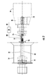
- Figs. 2-4 provide perspective, top, and side views, respectively, of a system 40 for supporting the shaft 32 according to one embodiment of the present invention
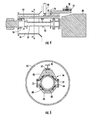
- Fig. 5 provides an axial cross-section view of the system 40 shown in Fig. 4 taken along line A-A rigidly connected to the shaft 32.
- the system 40 may comprise a support member 42, a plurality of nests 44, and a counterweight 46.
- the support member 42 may comprise any suitable structure for supporting the combined weight of the shaft 32, nests 42, and counterweight 46, if present.
- the support member 42 may comprise an I-beam, a reinforced bar, or another suitable structure known to one of ordinary skill in the art.
- the support member 42 is generally divided into a load portion 48 and a counterweight portion 50 separated by a fulcrum 52 between the load portion 48 and the counterweight portion 50.
- the support member 42 may be symmetric or asymmetric between the load portion 48 and the counterweight portion 50.
- the load portion 48 is configured or sized to fit or extend inside the turbine 16, exhaust frame 36, and/or the tunnel 34, depending on the particular embodiment.
- the load portion 48 of the support member 42 may be inserted inside the turbine 16, exhaust frame 36, and/or tunnel 34, and a crane 54 may be connected to the fulcrum 52 to lift the system 40 as desired.
- the crane 54 may comprise any suitable device rated to lift the combined weight of the system 40 and shaft 32.
- the crane 54 may comprise a stationary crane, a portable crane, or an overhead crane, as shown in Figs. 2 and 4 .
- the plurality of nests 44 may be connected to the support member 42 at desired positions between the load portion 48 and the counterweight portion 50 to rigidly connect the shaft 32 to the support member 42.
- the nests 44 may comprise, for example, clamps, ropes, cords, brackets, and/or fasteners 56, as shown most clearly in Figs. 2 and 5 .
- the fasteners 56 may extend downward from the support member 42 to rigidly connect the shaft 32 to the support member 42.
- each fastener 56 may comprise a first portion or an upper section 58 releasably connected to a second portion or a lower section 60.
- the upper section 58 may be fixedly connected to the support member 42, such as by bolting a flange 62 of the upper section 58 to the support member 42.
- the upper section 58 of one or more fasteners 56 may be slidingly connected to the support member 42 so that the position of one or more fasteners 56 may be adjusted between the load portion 48 and the counterweight portion 50, depending on the particular dimensions, shape, and length of the shaft 32.
- the support member 42 may include a plurality of bolt holes 64 that allow the flange 62 of the upper section 58 to slide along the support member 42 before being bolted in the desired position.
- the lower section 60 is opposed to the upper section 58 and may releasably connect to the upper section 58 using, for example, bolts, clamps, or turnbuckles 66 as shown in Figs. 2 and 5 .
- the upper and lower sections 58, 60 When the upper and lower sections 58, 60 are connected to one another, they may define an internal surface 68 that substantially conforms to an external surface 70 of the shaft 32 to rigidly connect the shaft 32 to the support member 42.
- the internal surface 68 of the fastener 56 may be circular to more precisely conform to the external surface 70 of the shaft 32.
- the internal surface 68 may be polygonal to substantially conform to shafts 32 having a varying and/or non-circular external surface 70.
- the nests 44 or fasteners 56 may further include one or more pads 72 or similar shock absorbing material to further support and cushion the shaft 32 when connected to the support member 42.
- the counterweight 46 may be connected to the support member 42 and configured to move along the support member 42 only on the counterweight portion 50 of the support member 42 to balance the weight of the shaft 32 across the fulcrum 52.
- the system 40 may include means for moving the counterweight 46 along the counterweight portion 50 of the support member 42 toward or away from the fulcrum 52.
- the means for moving the counterweight 46 may comprise any suitable mechanism for moving one object with respect to another.
- the means for moving the counterweight 46 may comprise a pneumatic piston, a hydraulic piston, a gear, a ratchet and pawl, or other mechanical or servo-mechanical device known to one of ordinary skill in the art. In the particular embodiment shown in Figs.
- the means for moving the counterweight 46 comprises a bolt 74 in threaded engagement with the support member 42.
- a wrench, drill, or other suitable tool may be applied to the bolt 74 to rotate the bolt 74 clockwise or counterclockwise to alternately move the counterweight toward or away from the fulcrum 52 on the counterweight portion 50 of the support member 42.
- the system 40 may include a sensor 76 connected to the support member 42 to measure or determine a horizontal angle of the support member 42.
- the sensor 76 may comprise any suitable instrument for detecting and measuring the horizontal attitude of the support member 42.
- the sensor 76 may comprise a level containing a viscous fluid that readily indicates the horizontal attitude of the support member 42.
- the sensor 76 will indicate any change in the horizontal attitude of the support member 42, and the position of the counterweight 46 on the counterweight portion 50 of the support member 42 may be adjusted to achieve a desired horizontal attitude of the support member 42 to facilitate movement of the shaft 32 into or out of the turbine 16, exhaust frame 36, and/or tunnel 34.
- the system 40 may further include a controller 78 connected to the sensor 76 and the means for moving the counterweight 46.
- the technical effect of the controller 78 is to receive an attitude signal 80 from the sensor 76 and generate a control signal 82 to the means for moving the counterweight 46 to move the counterweight 46 on the support member 42 to position the support member 42 at a predetermined horizontal angle or attitude.
- the controller 78 may comprise any combination of microprocessors, circuitry, or other programmed logic circuit and is not limited to any particular hardware architecture or configuration. Embodiments of the systems and methods set forth herein may be implemented by one or more general-purpose or customized controllers 78 adapted in any suitable manner to provide the desired functionality.
- the controller 78 may be adapted to provide additional functionality, either complementary or unrelated to the present subject matter.
- one or more controllers 78 may be adapted to provide the described functionality by accessing software instructions rendered in a computer-readable form.
- any suitable programming, scripting, or other type of language or combinations of languages may be used to implement the teachings contained herein.
- software need not be used exclusively, or at all.
- some embodiments of the systems and methods set forth and disclosed herein may also be implemented by hardwired logic or other circuitry, including, but not limited to application-specific circuits. Of course, various combinations of computer-executed software and hardwired logic or other circuitry may be suitable, as well.
- the system 40 described and illustrated with respect to Figs. 2-5 may thus provide a method for supporting the shaft 32 inside the turbine 16.
- the method generally includes inserting the support member 42 at least partially inside the turbine 16, positioning the nests 44 on the support member 42 to correspond to a predetermined position on the shaft 32, and connecting the shaft 32 to the support member.
- the shaft 32 may then be supported by the system 40 and disconnected from the turbine 16 and workpiece 38.
- the crane 54 may be connected to the fulcrum 48 to lift the support member 42 and shaft 32, and the counterweight 46 may be moved on the support member 42 achieve a desired horizontal attitude of the support member 42 while moving the shaft 32.
- the method may further include measuring the horizontal angle of the support member 42 and adjusting the position of the counterweight 46 as the shaft 32 is moved inside the turbine 16.
- the method allows the shaft 32 to be safely, reliably, and efficiently supported as the shaft 32 is installed or removed from the turbine 16.
Landscapes
- Engineering & Computer Science (AREA)
- Mechanical Engineering (AREA)
- General Engineering & Computer Science (AREA)
- Jib Cranes (AREA)
- Load-Engaging Elements For Cranes (AREA)
- Structures Of Non-Positive Displacement Pumps (AREA)
Abstract
Description
- The present invention generally involves a system and method for supporting a shaft inside a turbine. In particular embodiments, the system and method may be used to install and/or remove the shaft from the turbine during maintenance and repairs.
- Turbines are known in the art for extracting energy from a fluid and converting the extracted energy into work. For example, a typical turbine includes alternating stages of stationary nozzles attached to an outer casing and rotating blades attached to a rotor. As a working fluid, such as steam, air, or combustion gases, flows through the turbine, the stationary nozzles redirect and accelerate the working fluid onto the subsequent stage of rotating blades to cause the rotating blades to turn the rotor. A shaft typically couples the rotor to a work piece so that rotation of the rotor turns the work piece. For example, the shaft may couple the rotor to a generator so that rotation of the rotor operates the generator to produce electricity.
- The shaft typically extends through a tunnel that is itself located inside an exhaust frame that surrounds the turbine. Occasionally, sections of the shaft must be removed from the turbine to facilitate maintenance and/or repairs to the turbine or associated components. Sections of the shaft are delicately balanced and may weigh anywhere from several hundred to several thousand pounds, or more. In addition, access to the shaft is somewhat restricted by the surrounding tunnel and exhaust frame. As a result, removal and installation of the shaft presents a number of difficulties such as a confined space, pinch points, and awkward manual lifting of the shaft. In addition, no special tools exist to lift, support, and remove the shaft with the exhaust frame installed. As a result, the weight of the shaft implicates safety and health concerns to avoid personnel injuries and/or damage to the shaft or nearby equipment, and the time required to safely move the shaft implicates the duration of the outage associated with the maintenance and/or repairs.
- Various systems and methods have been used to support the shaft during installation and removal of the shaft from the turbine. For example, the shaft may be manually supported by a sufficient number of workers until the shaft is clear of the exhaust frame and can be supported by chain falls and/or a crane. Although this method is relatively expedient, it may create unacceptable health or safety risks to the workers, may require partial or complete removal of the exhaust frame, and may not be possible for heavier shafts. Another technique is to construct a temporary track in the tunnel or exhaust frame to support the shaft. Although the track reduces the health and safety risks, the construction and subsequent removal of the track is itself time consuming and may extend the duration of the outage associated with the maintenance and/or repairs. Therefore, an improved system and method for supporting the shaft during installation and/or removal would be useful.
- Aspects and advantages of the invention are set forth below in the following description, or may be apparent from the description, or may be learned through practice of the invention.
- One embodiment of the present invention is a system for supporting a shaft inside a turbine. The system includes a support member having a load portion and a counterweight portion. A fulcrum on the support member is between the load portion and the counterweight portion, and the load portion is configured to fit inside the turbine. A plurality of nests are connected to the support member between the load portion and the counterweight portion, and the plurality of nests are configured to rigidly connect the shaft to the support member. A counterweight is connected to move along the support member only on the counterweight portion of the support member.
- Another embodiment of the present invention is a system for supporting a shaft inside a turbine that includes a support member having a load portion and a counterweight portion. A fulcrum on the support member is between the load portion and the counterweight portion. A plurality of fasteners extend from the support member between the load portion and the counterweight portion and are configured to rigidly connect the shaft to the support member. The system further includes means for moving a counterweight only on the counterweight portion toward or away from the fulcrum.
- The present invention may also include a method for supporting a shaft inside a turbine. The method includes inserting a support member at least partially inside the turbine and connecting the shaft to the support member. The method further includes connecting a crane to a fulcrum on the support member, lifting the support member and shaft with the crane, and moving a counterweight on the support member to change a horizontal angle of the support member.
- Those of ordinary skill in the art will better appreciate the features and aspects of such embodiments, and others, upon review of the specification.
- A full and enabling disclosure of the present invention, including the best mode thereof to one skilled in the art, is set forth more particularly in the remainder of the specification, including reference to the accompanying figures, in which:
-
Fig. 1 is a simplified plan view of an exemplary gas turbine; -
Fig. 2 is a perspective view of a system for supporting the shaft according to one embodiment of the present invention; -
Fig. 3 is a top plan view of the system shown inFig. 2 removing the shaft; -
Fig. 4 is a side plan view of the system shown inFig. 2 removing the shaft; and -
Fig. 5 is an axial cross-section view of the system shown inFig. 4 taken along line A-A rigidly connected to the shaft. - Reference will now be made in detail to present embodiments of the invention, one or more examples of which are illustrated in the accompanying drawings. The detailed description uses numerical and letter designations to refer to features in the drawings. Like or similar designations in the drawings and description have been used to refer to like or similar parts of the invention.
- Each example is provided by way of explanation of the invention, not limitation of the invention. In fact, it will be apparent to those skilled in the art that modifications and variations can be made in the present invention without departing from the scope thereof. For instance, features illustrated or described as part of one embodiment may be used on another embodiment to yield a still further embodiment. Thus, it is intended that the present invention covers such modifications and variations as come within the scope of the appended claims and their equivalents.
- Various embodiments of the present invention include a system and method for supporting a shaft in a turbine. In particular embodiments, a support member may be inserted into the tunnel adjacent to the shaft and rigidly attached to the shaft. A counterweight may be used to balance the weight of the shaft on the support member as a crane attached to a fulcrum on the support member lifts the support member and attached shaft out of the turbine. The system and method thus reduces the health and safety risks as well as the time required to remove and/or install the shaft with respect to the turbine.
-
Fig. 1 is a simplified plan view of anexemplary gas turbine 10. As shown, thegas turbine 10 generally includes anaxial compressor 12 at the front, one ormore combustors 14 downstream from thecompressor 12, and aturbine 16 downstream from thecombustors 14. As used herein, the terms "upstream" and "downstream" refer to the relative location of components in a fluid pathway. For example, component A is upstream of component B if a fluid flows from component A to component B. Conversely, component B is downstream of component A if component B receives a fluid flow from component A. - Ambient air may be supplied to the
compressor 12, and rotatingblades 18 andstationary vanes 20 in thecompressor 12 progressively impart kinetic energy to the working fluid (air) to produce a compressed working fluid at a highly energized state. The compressed working fluid exits thecompressor 12 and flows into acombustion chamber 22 in eachcombustor 14. Afuel supply 24 in fluid communication with eachcombustor 14 supplies a fuel to eachcombustion chamber 22, and the compressed working fluid mixes with the fuel and ignites to generate combustion gases having a high temperature and pressure. The combustion gases flow along ahot gas path 26 through theturbine 16 where they expand to produce work. Specifically, the combustion gases may flow across alternating stages ofstationary nozzles 28 and rotatingbuckets 30 in thehot gas path 26 to rotate ashaft 32. As shown inFig. 1 , at least a portion of theshaft 32 may extend through atunnel 34 inside andexhaust frame 36 of theturbine 16. In this manner, theshaft 32 may connect to aworkpiece 38 outside of theturbine 16 to produce work. -
Figs. 2-4 provide perspective, top, and side views, respectively, of asystem 40 for supporting theshaft 32 according to one embodiment of the present invention, andFig. 5 provides an axial cross-section view of thesystem 40 shown inFig. 4 taken along line A-A rigidly connected to theshaft 32. In particular embodiments, thesystem 40 may comprise asupport member 42, a plurality ofnests 44, and acounterweight 46. Thesupport member 42 may comprise any suitable structure for supporting the combined weight of theshaft 32,nests 42, andcounterweight 46, if present. For example, thesupport member 42 may comprise an I-beam, a reinforced bar, or another suitable structure known to one of ordinary skill in the art. Thesupport member 42 is generally divided into aload portion 48 and acounterweight portion 50 separated by a fulcrum 52 between theload portion 48 and thecounterweight portion 50. Thesupport member 42 may be symmetric or asymmetric between theload portion 48 and thecounterweight portion 50. In any event, theload portion 48 is configured or sized to fit or extend inside theturbine 16,exhaust frame 36, and/or thetunnel 34, depending on the particular embodiment. In this manner, theload portion 48 of thesupport member 42 may be inserted inside theturbine 16,exhaust frame 36, and/ortunnel 34, and acrane 54 may be connected to the fulcrum 52 to lift thesystem 40 as desired. Thecrane 54 may comprise any suitable device rated to lift the combined weight of thesystem 40 andshaft 32. For example, thecrane 54 may comprise a stationary crane, a portable crane, or an overhead crane, as shown inFigs. 2 and4 . - The plurality of
nests 44 may be connected to thesupport member 42 at desired positions between theload portion 48 and thecounterweight portion 50 to rigidly connect theshaft 32 to thesupport member 42. Thenests 44 may comprise, for example, clamps, ropes, cords, brackets, and/orfasteners 56, as shown most clearly inFigs. 2 and5 . Thefasteners 56 may extend downward from thesupport member 42 to rigidly connect theshaft 32 to thesupport member 42. For example, as shown most clearly inFigs. 2 and5 , eachfastener 56 may comprise a first portion or anupper section 58 releasably connected to a second portion or alower section 60. - The
upper section 58 may be fixedly connected to thesupport member 42, such as by bolting aflange 62 of theupper section 58 to thesupport member 42. In particular embodiments, theupper section 58 of one ormore fasteners 56 may be slidingly connected to thesupport member 42 so that the position of one ormore fasteners 56 may be adjusted between theload portion 48 and thecounterweight portion 50, depending on the particular dimensions, shape, and length of theshaft 32. For example, as shown most clearly inFig. 2 , thesupport member 42 may include a plurality of bolt holes 64 that allow theflange 62 of theupper section 58 to slide along thesupport member 42 before being bolted in the desired position. - The
lower section 60 is opposed to theupper section 58 and may releasably connect to theupper section 58 using, for example, bolts, clamps, orturnbuckles 66 as shown inFigs. 2 and5 . When the upper andlower sections internal surface 68 that substantially conforms to anexternal surface 70 of theshaft 32 to rigidly connect theshaft 32 to thesupport member 42. For example, theinternal surface 68 of thefastener 56 may be circular to more precisely conform to theexternal surface 70 of theshaft 32. Alternately, as shown inFigs. 2 and5 , theinternal surface 68 may be polygonal to substantially conform toshafts 32 having a varying and/or non-circularexternal surface 70. In particular embodiments, thenests 44 orfasteners 56 may further include one ormore pads 72 or similar shock absorbing material to further support and cushion theshaft 32 when connected to thesupport member 42. - As shown most clearly in
Figs. 2 and4 , thecounterweight 46 may be connected to thesupport member 42 and configured to move along thesupport member 42 only on thecounterweight portion 50 of thesupport member 42 to balance the weight of theshaft 32 across thefulcrum 52. For example, thesystem 40 may include means for moving thecounterweight 46 along thecounterweight portion 50 of thesupport member 42 toward or away from thefulcrum 52. The means for moving thecounterweight 46 may comprise any suitable mechanism for moving one object with respect to another. For example, the means for moving thecounterweight 46 may comprise a pneumatic piston, a hydraulic piston, a gear, a ratchet and pawl, or other mechanical or servo-mechanical device known to one of ordinary skill in the art. In the particular embodiment shown inFigs. 2-4 , the means for moving thecounterweight 46 comprises abolt 74 in threaded engagement with thesupport member 42. A wrench, drill, or other suitable tool may be applied to thebolt 74 to rotate thebolt 74 clockwise or counterclockwise to alternately move the counterweight toward or away from the fulcrum 52 on thecounterweight portion 50 of thesupport member 42. - The precise position of the
counterweight 46 on thecounterweight portion 50 of thesupport member 42 required to balance the weight of theshaft 32 across the fulcrum 52 may be determined by calculations factoring in the weight of theshaft 32, the weight of thecounterweight 46, and the moment arms of the load andcounterweight portions system 40 may include asensor 76 connected to thesupport member 42 to measure or determine a horizontal angle of thesupport member 42. Thesensor 76 may comprise any suitable instrument for detecting and measuring the horizontal attitude of thesupport member 42. For example, as shown most clearly inFigs. 2 and3 , thesensor 76 may comprise a level containing a viscous fluid that readily indicates the horizontal attitude of thesupport member 42. In this manner, as thenests 44 rigidly connect theshaft 32 to thesupport member 42, thesensor 76 will indicate any change in the horizontal attitude of thesupport member 42, and the position of thecounterweight 46 on thecounterweight portion 50 of thesupport member 42 may be adjusted to achieve a desired horizontal attitude of thesupport member 42 to facilitate movement of theshaft 32 into or out of theturbine 16,exhaust frame 36, and/ortunnel 34. - In particular embodiments, the
system 40 may further include acontroller 78 connected to thesensor 76 and the means for moving thecounterweight 46. The technical effect of thecontroller 78 is to receive anattitude signal 80 from thesensor 76 and generate acontrol signal 82 to the means for moving thecounterweight 46 to move thecounterweight 46 on thesupport member 42 to position thesupport member 42 at a predetermined horizontal angle or attitude. As used herein, thecontroller 78 may comprise any combination of microprocessors, circuitry, or other programmed logic circuit and is not limited to any particular hardware architecture or configuration. Embodiments of the systems and methods set forth herein may be implemented by one or more general-purpose or customizedcontrollers 78 adapted in any suitable manner to provide the desired functionality. Thecontroller 78 may be adapted to provide additional functionality, either complementary or unrelated to the present subject matter. For instance, one ormore controllers 78 may be adapted to provide the described functionality by accessing software instructions rendered in a computer-readable form. When software is used, any suitable programming, scripting, or other type of language or combinations of languages may be used to implement the teachings contained herein. However, software need not be used exclusively, or at all. For example, as will be understood by those of ordinary skill in the art without required additional detailed discussion, some embodiments of the systems and methods set forth and disclosed herein may also be implemented by hardwired logic or other circuitry, including, but not limited to application-specific circuits. Of course, various combinations of computer-executed software and hardwired logic or other circuitry may be suitable, as well. - The
system 40 described and illustrated with respect toFigs. 2-5 may thus provide a method for supporting theshaft 32 inside theturbine 16. The method generally includes inserting thesupport member 42 at least partially inside theturbine 16, positioning thenests 44 on thesupport member 42 to correspond to a predetermined position on theshaft 32, and connecting theshaft 32 to the support member. Theshaft 32 may then be supported by thesystem 40 and disconnected from theturbine 16 andworkpiece 38. Thecrane 54 may be connected to the fulcrum 48 to lift thesupport member 42 andshaft 32, and thecounterweight 46 may be moved on thesupport member 42 achieve a desired horizontal attitude of thesupport member 42 while moving theshaft 32. Depending on the particular embodiment, the method may further include measuring the horizontal angle of thesupport member 42 and adjusting the position of thecounterweight 46 as theshaft 32 is moved inside theturbine 16. As a result, the method allows theshaft 32 to be safely, reliably, and efficiently supported as theshaft 32 is installed or removed from theturbine 16. - This written description uses examples to disclose the invention, including the best mode, and also to enable any person skilled in the art to practice the invention, including making and using any devices or systems and performing any incorporated methods. The patentable scope of the invention is defined by the claims, and may include other examples that occur to those skilled in the art. Such other examples are intended to be within the scope of the claims if they include structural elements that do not differ from the literal language of the claims, or if they include equivalent structural elements with insubstantial differences from the literal language of the claims.
Claims (14)
- A system (40) for supporting a shaft (32) inside a turbine (16), comprising:a. a support member (42), wherein said support member (42) comprises a load portion (48) and a counterweight portion (50);b. a fulcrum (52) on said support member (42) between said load portion (48) and said counterweight portion (50), wherein said load portion (48) is configured to fit inside the turbine (16);c. a plurality of nests (44) connected to said support member (42) between said load portion (48) and said counterweight portion (50), wherein said plurality of nests (44) are configured to rigidly connect the shaft (32) to said support member (42); andd. a counterweight (46) connected to move along said support member (42) only on said counterweight portion (50) of said support member (42).
- The system (40) as in any preceding claim, wherein each nest (44) comprises a clamp having a first portion (58) fixedly attached to said support member (42) and a second portion (60) opposed to said first portion (58).
- The system (40) as in any preceding claim, wherein each nest (44) comprises an internal surface (68) that substantially conforms to an external surface of the shaft (70).
- The system (40) as in any preceding claim, where at least one nest (44) is slidingly connected to said support member (42).
- The system (40) as in any preceding claim, further comprising means for moving said counterweight (46) along said counterweight portion (50) of said support member (42).
- The system (40) as in any preceding claim, further comprising a crane (54) connected to said fulcrum (52).
- The system (40) as in any preceding claim, further comprising a sensor (76) connected to said support member (42), wherein said sensor (76) determines a horizontal angle of said support member (42).
- The system (40) as in any preceding claim, further comprising a controller (78) configured to move said counterweight (46) on said support member (42) to position said support member (42) at a predetermined horizontal angle.
- A method for supporting a shaft (32) inside a turbine (16), comprising:a. inserting a support member (42) at least partially inside said turbine (16);b. connecting said shaft (32) to said support member (42);c. connecting a crane (54) to a fulcrum (52) on said support member (42);d. lifting said support member (42) and said shaft (32) with said crane (54); ande. moving a counterweight (46) on said support member (42) to change a horizontal angle of said support member (42).
- The method as in claim 9, further comprising measuring a horizontal angle of said support member (42).
- The method as in any of claims 9-10, wherein connecting said shaft (32) to said support member (42) includes rigidly connecting said shaft (32) to said support member (42).
- The method as in any of claims 9-11, further comprising positioning a nest (44) on said support member (42) to correspond with a predetermined position on said shaft (32).
- The method as in any of claims 9-12, further comprising cushioning said shaft (32) against said support member (42).
- The method as in any of claims 9-13, further comprising withdrawing said support member (42) connected to said shaft (32) from said turbine (16).
Applications Claiming Priority (1)
| Application Number | Priority Date | Filing Date | Title |
|---|---|---|---|
| US13/191,744 US8789866B2 (en) | 2011-07-27 | 2011-07-27 | System and method for supporting a shaft inside a turbine |
Publications (3)
| Publication Number | Publication Date |
|---|---|
| EP2551474A2 true EP2551474A2 (en) | 2013-01-30 |
| EP2551474A3 EP2551474A3 (en) | 2018-03-21 |
| EP2551474B1 EP2551474B1 (en) | 2021-03-10 |
Family
ID=46603658
Family Applications (1)
| Application Number | Title | Priority Date | Filing Date |
|---|---|---|---|
| EP12178223.9A Active EP2551474B1 (en) | 2011-07-27 | 2012-07-27 | Method for supporting a shaft inside a turbine |
Country Status (3)
| Country | Link |
|---|---|
| US (1) | US8789866B2 (en) |
| EP (1) | EP2551474B1 (en) |
| CN (1) | CN102900541B (en) |
Cited By (3)
| Publication number | Priority date | Publication date | Assignee | Title |
|---|---|---|---|---|
| EP3034450A1 (en) * | 2014-12-19 | 2016-06-22 | Airbus Defence and Space, S.A. | Device for hoisting and controlling loads |
| FR3160728A1 (en) * | 2024-03-27 | 2025-10-03 | Safran Aircraft Engines | Turbomachine assembly device |
| FR3160727A1 (en) * | 2024-03-27 | 2025-10-03 | Safran Aircraft Engines | Turbomachine assembly device |
Families Citing this family (7)
| Publication number | Priority date | Publication date | Assignee | Title |
|---|---|---|---|---|
| DE102011056631A1 (en) * | 2011-12-19 | 2013-06-20 | Rud Ketten Rieger & Dietz Gmbh U. Co. Kg | Rocker for hangers with display arrangement |
| EP3217748B1 (en) * | 2014-11-06 | 2021-02-17 | Huawei Technologies Co., Ltd. | Data transmission method and apparatus |
| RU2671611C1 (en) * | 2015-07-06 | 2018-11-02 | Дрессер-Рэнд Компани | Reinforced construction for rotating mechanisms |
| CN105347168B (en) * | 2015-11-03 | 2017-12-29 | 中国北车集团大连机车车辆有限公司 | Diesel-engine body bent axle cylinder sleeve chamber core hoisting appliance |
| US10788398B2 (en) * | 2016-12-23 | 2020-09-29 | Rolls-Royce Corporation | Gas turbine engine test stand |
| CN107098260B (en) * | 2017-06-08 | 2018-06-22 | 北京天朔新能源汽车有限公司 | A kind of automatic handling robot of electric vehicle special (purpose) rubber tire |
| FR3085710B1 (en) * | 2018-09-12 | 2020-09-11 | Safran Aircraft Engines | REMOVABLE SUPPORT INTERFACE FOR TURBOMACHINE ANNULAR CASE |
Family Cites Families (21)
| Publication number | Priority date | Publication date | Assignee | Title |
|---|---|---|---|---|
| US2246142A (en) * | 1940-12-24 | 1941-06-17 | Carl E Moore | Balanced lifting device |
| US3253851A (en) * | 1963-11-07 | 1966-05-31 | Presray Corp | Rotating sling |
| US3433459A (en) * | 1967-05-02 | 1969-03-18 | Federal Sign And Signal Corp | Load handling apparatus |
| US3596968A (en) * | 1970-01-09 | 1971-08-03 | Behring Corp | Lifting apparatus |
| US3675961A (en) * | 1970-06-24 | 1972-07-11 | Charles B Wheeler | Horizontal load positioner |
| US3762755A (en) * | 1971-06-21 | 1973-10-02 | K Saether | Hoisting accessory |
| US3847429A (en) * | 1973-05-07 | 1974-11-12 | Gulf & Western Mfg Co | Balance bar for handling wrapper rolls of a strip coiling machine |
| US4017109A (en) * | 1976-01-07 | 1977-04-12 | Belinsky Sidney I | Hoisting device for a crane |
| US4251098A (en) * | 1978-12-04 | 1981-02-17 | Belinsky Sidney I | Under-the-roof loader |
| US4433830A (en) * | 1981-12-03 | 1984-02-28 | Westinghouse Electric Corp. | Lifting system for a turbine disc |
| US5800000A (en) * | 1996-12-23 | 1998-09-01 | Shockley; James D. | Load adjusting device for a hoist |
| US6048012A (en) | 1997-06-12 | 2000-04-11 | Selby; Cloyd R. | Understructure lifting beam |
| EP0962653B1 (en) * | 1998-06-04 | 2003-12-17 | Pietro Barozzi | Impulse-turbine |
| US7017963B1 (en) | 2004-05-17 | 2006-03-28 | Selby Arm, Inc. | Counter weighted lifting beam |
| US7396058B2 (en) * | 2006-01-17 | 2008-07-08 | Northrop Grumman Corporation | Balancing apparatus |
| US7559280B2 (en) * | 2006-04-28 | 2009-07-14 | United Technologies Corporation | Adjustable link system |
| ITMI20061460A1 (en) * | 2006-07-26 | 2008-01-27 | Techint Spa | LOCKING DEVICE FOR LAMINATION CYLINDER HANDLING SYSTEMS |
| US8000835B2 (en) * | 2006-12-01 | 2011-08-16 | Lockheed Martin Corporation | Center of gravity sensing and adjusting load bar, program product, and related methods |
| US8317244B1 (en) * | 2008-08-22 | 2012-11-27 | Jay Wesley Schuyleman | Apparatus and method for positioning an object in a building |
| CN201713287U (en) * | 2010-04-15 | 2011-01-19 | 上海电气电站设备有限公司 | Gas turbine rotor hoisting device |
| US8608143B2 (en) * | 2011-12-13 | 2013-12-17 | Wayne Michael Williams | Pipe clamp device and a method for its use |
-
2011
- 2011-07-27 US US13/191,744 patent/US8789866B2/en active Active
-
2012
- 2012-07-26 CN CN201210260815.4A patent/CN102900541B/en active Active
- 2012-07-27 EP EP12178223.9A patent/EP2551474B1/en active Active
Non-Patent Citations (1)
| Title |
|---|
| None |
Cited By (4)
| Publication number | Priority date | Publication date | Assignee | Title |
|---|---|---|---|---|
| EP3034450A1 (en) * | 2014-12-19 | 2016-06-22 | Airbus Defence and Space, S.A. | Device for hoisting and controlling loads |
| US10106376B2 (en) | 2014-12-19 | 2018-10-23 | Airbus Defence And Space, S.A. | Device for hoisting and controlling loads |
| FR3160728A1 (en) * | 2024-03-27 | 2025-10-03 | Safran Aircraft Engines | Turbomachine assembly device |
| FR3160727A1 (en) * | 2024-03-27 | 2025-10-03 | Safran Aircraft Engines | Turbomachine assembly device |
Also Published As
| Publication number | Publication date |
|---|---|
| US20130028699A1 (en) | 2013-01-31 |
| CN102900541B (en) | 2016-10-05 |
| US8789866B2 (en) | 2014-07-29 |
| EP2551474A3 (en) | 2018-03-21 |
| EP2551474B1 (en) | 2021-03-10 |
| CN102900541A (en) | 2013-01-30 |
Similar Documents
| Publication | Publication Date | Title |
|---|---|---|
| US8789866B2 (en) | System and method for supporting a shaft inside a turbine | |
| US8402625B2 (en) | System and method for modifying a rotor | |
| US9885255B2 (en) | System for positioning of equipment | |
| US20190072005A1 (en) | Turbine bearing maintenance apparatus and method | |
| US9322504B2 (en) | Apparatus and system for positioning of equipment | |
| EP2226475A2 (en) | Alignment device for gas turbine casings | |
| JP7034665B2 (en) | Installing or removing turbine blades at the base of the turbine blades | |
| US8984730B2 (en) | System and method for rotating a turbine shell | |
| US10132243B2 (en) | Mounting and dismounting device for a liner of a gas turbine and a related method | |
| CN105000462A (en) | Split type hoisting method for 5MW land type wind generating set | |
| EP2514924A2 (en) | System and method for modifying a slot in a rotor | |
| US9896973B2 (en) | Assembly tool for exhaust turbochargers | |
| EP2557277A2 (en) | Method and Apparatus to Facilitate Turbine Casing Assembly | |
| EP2811123A1 (en) | Apparatus for pivoting an upper portion of a turbine shell | |
| US10519810B2 (en) | Manipulation of turbomachine combustors | |
| EP2730753B1 (en) | A system for assembling and disassembling a turbine section of a gas turbine | |
| EP3293359B1 (en) | Manipulation of turbomachine combustors | |
| EP3477066B1 (en) | Installation apparatus for a load-coupling of a turbine system and method of installing a load-coupling in a turbine system | |
| KR20160065599A (en) | Turbine case lifting system and the method using the system | |
| US10024164B2 (en) | Fixture for restraining a turbine wheel | |
| KR20240135983A (en) | Exchanging apparatus and method | |
| CN118979614A (en) | A maintenance platform for turbine seat ring | |
| WO2018063667A1 (en) | Fixture for restraining a turbine wheel and corresponding method |
Legal Events
| Date | Code | Title | Description |
|---|---|---|---|
| PUAI | Public reference made under article 153(3) epc to a published international application that has entered the european phase |
Free format text: ORIGINAL CODE: 0009012 |
|
| AK | Designated contracting states |
Kind code of ref document: A2 Designated state(s): AL AT BE BG CH CY CZ DE DK EE ES FI FR GB GR HR HU IE IS IT LI LT LU LV MC MK MT NL NO PL PT RO RS SE SI SK SM TR |
|
| AX | Request for extension of the european patent |
Extension state: BA ME |
|
| PUAL | Search report despatched |
Free format text: ORIGINAL CODE: 0009013 |
|
| AK | Designated contracting states |
Kind code of ref document: A3 Designated state(s): AL AT BE BG CH CY CZ DE DK EE ES FI FR GB GR HR HU IE IS IT LI LT LU LV MC MK MT NL NO PL PT RO RS SE SI SK SM TR |
|
| AX | Request for extension of the european patent |
Extension state: BA ME |
|
| RIC1 | Information provided on ipc code assigned before grant |
Ipc: F01D 25/28 20060101AFI20180212BHEP |
|
| STAA | Information on the status of an ep patent application or granted ep patent |
Free format text: STATUS: REQUEST FOR EXAMINATION WAS MADE |
|
| 17P | Request for examination filed |
Effective date: 20180921 |
|
| RBV | Designated contracting states (corrected) |
Designated state(s): AL AT BE BG CH CY CZ DE DK EE ES FI FR GB GR HR HU IE IS IT LI LT LU LV MC MK MT NL NO PL PT RO RS SE SI SK SM TR |
|
| STAA | Information on the status of an ep patent application or granted ep patent |
Free format text: STATUS: EXAMINATION IS IN PROGRESS |
|
| 17Q | First examination report despatched |
Effective date: 20191204 |
|
| GRAP | Despatch of communication of intention to grant a patent |
Free format text: ORIGINAL CODE: EPIDOSNIGR1 |
|
| STAA | Information on the status of an ep patent application or granted ep patent |
Free format text: STATUS: GRANT OF PATENT IS INTENDED |
|
| INTG | Intention to grant announced |
Effective date: 20201217 |
|
| GRAS | Grant fee paid |
Free format text: ORIGINAL CODE: EPIDOSNIGR3 |
|
| GRAA | (expected) grant |
Free format text: ORIGINAL CODE: 0009210 |
|
| STAA | Information on the status of an ep patent application or granted ep patent |
Free format text: STATUS: THE PATENT HAS BEEN GRANTED |
|
| AK | Designated contracting states |
Kind code of ref document: B1 Designated state(s): AL AT BE BG CH CY CZ DE DK EE ES FI FR GB GR HR HU IE IS IT LI LT LU LV MC MK MT NL NO PL PT RO RS SE SI SK SM TR |
|
| REG | Reference to a national code |
Ref country code: GB Ref legal event code: FG4D |
|
| REG | Reference to a national code |
Ref country code: AT Ref legal event code: REF Ref document number: 1370019 Country of ref document: AT Kind code of ref document: T Effective date: 20210315 Ref country code: CH Ref legal event code: EP |
|
| REG | Reference to a national code |
Ref country code: DE Ref legal event code: R096 Ref document number: 602012074697 Country of ref document: DE |
|
| REG | Reference to a national code |
Ref country code: IE Ref legal event code: FG4D |
|
| REG | Reference to a national code |
Ref country code: LT Ref legal event code: MG9D |
|
| PG25 | Lapsed in a contracting state [announced via postgrant information from national office to epo] |
Ref country code: LT Free format text: LAPSE BECAUSE OF FAILURE TO SUBMIT A TRANSLATION OF THE DESCRIPTION OR TO PAY THE FEE WITHIN THE PRESCRIBED TIME-LIMIT Effective date: 20210310 Ref country code: GR Free format text: LAPSE BECAUSE OF FAILURE TO SUBMIT A TRANSLATION OF THE DESCRIPTION OR TO PAY THE FEE WITHIN THE PRESCRIBED TIME-LIMIT Effective date: 20210611 Ref country code: HR Free format text: LAPSE BECAUSE OF FAILURE TO SUBMIT A TRANSLATION OF THE DESCRIPTION OR TO PAY THE FEE WITHIN THE PRESCRIBED TIME-LIMIT Effective date: 20210310 Ref country code: FI Free format text: LAPSE BECAUSE OF FAILURE TO SUBMIT A TRANSLATION OF THE DESCRIPTION OR TO PAY THE FEE WITHIN THE PRESCRIBED TIME-LIMIT Effective date: 20210310 Ref country code: NO Free format text: LAPSE BECAUSE OF FAILURE TO SUBMIT A TRANSLATION OF THE DESCRIPTION OR TO PAY THE FEE WITHIN THE PRESCRIBED TIME-LIMIT Effective date: 20210610 Ref country code: BG Free format text: LAPSE BECAUSE OF FAILURE TO SUBMIT A TRANSLATION OF THE DESCRIPTION OR TO PAY THE FEE WITHIN THE PRESCRIBED TIME-LIMIT Effective date: 20210610 |
|
| REG | Reference to a national code |
Ref country code: AT Ref legal event code: MK05 Ref document number: 1370019 Country of ref document: AT Kind code of ref document: T Effective date: 20210310 |
|
| REG | Reference to a national code |
Ref country code: NL Ref legal event code: MP Effective date: 20210310 |
|
| PG25 | Lapsed in a contracting state [announced via postgrant information from national office to epo] |
Ref country code: SE Free format text: LAPSE BECAUSE OF FAILURE TO SUBMIT A TRANSLATION OF THE DESCRIPTION OR TO PAY THE FEE WITHIN THE PRESCRIBED TIME-LIMIT Effective date: 20210310 Ref country code: RS Free format text: LAPSE BECAUSE OF FAILURE TO SUBMIT A TRANSLATION OF THE DESCRIPTION OR TO PAY THE FEE WITHIN THE PRESCRIBED TIME-LIMIT Effective date: 20210310 Ref country code: LV Free format text: LAPSE BECAUSE OF FAILURE TO SUBMIT A TRANSLATION OF THE DESCRIPTION OR TO PAY THE FEE WITHIN THE PRESCRIBED TIME-LIMIT Effective date: 20210310 |
|
| PG25 | Lapsed in a contracting state [announced via postgrant information from national office to epo] |
Ref country code: NL Free format text: LAPSE BECAUSE OF FAILURE TO SUBMIT A TRANSLATION OF THE DESCRIPTION OR TO PAY THE FEE WITHIN THE PRESCRIBED TIME-LIMIT Effective date: 20210310 |
|
| PG25 | Lapsed in a contracting state [announced via postgrant information from national office to epo] |
Ref country code: CZ Free format text: LAPSE BECAUSE OF FAILURE TO SUBMIT A TRANSLATION OF THE DESCRIPTION OR TO PAY THE FEE WITHIN THE PRESCRIBED TIME-LIMIT Effective date: 20210310 Ref country code: EE Free format text: LAPSE BECAUSE OF FAILURE TO SUBMIT A TRANSLATION OF THE DESCRIPTION OR TO PAY THE FEE WITHIN THE PRESCRIBED TIME-LIMIT Effective date: 20210310 Ref country code: AT Free format text: LAPSE BECAUSE OF FAILURE TO SUBMIT A TRANSLATION OF THE DESCRIPTION OR TO PAY THE FEE WITHIN THE PRESCRIBED TIME-LIMIT Effective date: 20210310 Ref country code: SM Free format text: LAPSE BECAUSE OF FAILURE TO SUBMIT A TRANSLATION OF THE DESCRIPTION OR TO PAY THE FEE WITHIN THE PRESCRIBED TIME-LIMIT Effective date: 20210310 |
|
| PG25 | Lapsed in a contracting state [announced via postgrant information from national office to epo] |
Ref country code: RO Free format text: LAPSE BECAUSE OF FAILURE TO SUBMIT A TRANSLATION OF THE DESCRIPTION OR TO PAY THE FEE WITHIN THE PRESCRIBED TIME-LIMIT Effective date: 20210310 Ref country code: IS Free format text: LAPSE BECAUSE OF FAILURE TO SUBMIT A TRANSLATION OF THE DESCRIPTION OR TO PAY THE FEE WITHIN THE PRESCRIBED TIME-LIMIT Effective date: 20210710 Ref country code: PL Free format text: LAPSE BECAUSE OF FAILURE TO SUBMIT A TRANSLATION OF THE DESCRIPTION OR TO PAY THE FEE WITHIN THE PRESCRIBED TIME-LIMIT Effective date: 20210310 Ref country code: PT Free format text: LAPSE BECAUSE OF FAILURE TO SUBMIT A TRANSLATION OF THE DESCRIPTION OR TO PAY THE FEE WITHIN THE PRESCRIBED TIME-LIMIT Effective date: 20210712 Ref country code: ES Free format text: LAPSE BECAUSE OF FAILURE TO SUBMIT A TRANSLATION OF THE DESCRIPTION OR TO PAY THE FEE WITHIN THE PRESCRIBED TIME-LIMIT Effective date: 20210310 Ref country code: SK Free format text: LAPSE BECAUSE OF FAILURE TO SUBMIT A TRANSLATION OF THE DESCRIPTION OR TO PAY THE FEE WITHIN THE PRESCRIBED TIME-LIMIT Effective date: 20210310 |
|
| REG | Reference to a national code |
Ref country code: DE Ref legal event code: R097 Ref document number: 602012074697 Country of ref document: DE |
|
| PLBE | No opposition filed within time limit |
Free format text: ORIGINAL CODE: 0009261 |
|
| STAA | Information on the status of an ep patent application or granted ep patent |
Free format text: STATUS: NO OPPOSITION FILED WITHIN TIME LIMIT |
|
| PG25 | Lapsed in a contracting state [announced via postgrant information from national office to epo] |
Ref country code: AL Free format text: LAPSE BECAUSE OF FAILURE TO SUBMIT A TRANSLATION OF THE DESCRIPTION OR TO PAY THE FEE WITHIN THE PRESCRIBED TIME-LIMIT Effective date: 20210310 Ref country code: DK Free format text: LAPSE BECAUSE OF FAILURE TO SUBMIT A TRANSLATION OF THE DESCRIPTION OR TO PAY THE FEE WITHIN THE PRESCRIBED TIME-LIMIT Effective date: 20210310 |
|
| 26N | No opposition filed |
Effective date: 20211213 |
|
| PG25 | Lapsed in a contracting state [announced via postgrant information from national office to epo] |
Ref country code: SI Free format text: LAPSE BECAUSE OF FAILURE TO SUBMIT A TRANSLATION OF THE DESCRIPTION OR TO PAY THE FEE WITHIN THE PRESCRIBED TIME-LIMIT Effective date: 20210310 |
|
| REG | Reference to a national code |
Ref country code: CH Ref legal event code: PL |
|
| PG25 | Lapsed in a contracting state [announced via postgrant information from national office to epo] |
Ref country code: MC Free format text: LAPSE BECAUSE OF FAILURE TO SUBMIT A TRANSLATION OF THE DESCRIPTION OR TO PAY THE FEE WITHIN THE PRESCRIBED TIME-LIMIT Effective date: 20210310 |
|
| REG | Reference to a national code |
Ref country code: BE Ref legal event code: MM Effective date: 20210731 |
|
| PG25 | Lapsed in a contracting state [announced via postgrant information from national office to epo] |
Ref country code: LI Free format text: LAPSE BECAUSE OF NON-PAYMENT OF DUE FEES Effective date: 20210731 Ref country code: CH Free format text: LAPSE BECAUSE OF NON-PAYMENT OF DUE FEES Effective date: 20210731 |
|
| PG25 | Lapsed in a contracting state [announced via postgrant information from national office to epo] |
Ref country code: IS Free format text: LAPSE BECAUSE OF FAILURE TO SUBMIT A TRANSLATION OF THE DESCRIPTION OR TO PAY THE FEE WITHIN THE PRESCRIBED TIME-LIMIT Effective date: 20210710 Ref country code: LU Free format text: LAPSE BECAUSE OF NON-PAYMENT OF DUE FEES Effective date: 20210727 Ref country code: FR Free format text: LAPSE BECAUSE OF NON-PAYMENT OF DUE FEES Effective date: 20210731 |
|
| PG25 | Lapsed in a contracting state [announced via postgrant information from national office to epo] |
Ref country code: IE Free format text: LAPSE BECAUSE OF NON-PAYMENT OF DUE FEES Effective date: 20210727 Ref country code: BE Free format text: LAPSE BECAUSE OF NON-PAYMENT OF DUE FEES Effective date: 20210731 |
|
| PG25 | Lapsed in a contracting state [announced via postgrant information from national office to epo] |
Ref country code: HU Free format text: LAPSE BECAUSE OF FAILURE TO SUBMIT A TRANSLATION OF THE DESCRIPTION OR TO PAY THE FEE WITHIN THE PRESCRIBED TIME-LIMIT; INVALID AB INITIO Effective date: 20120727 Ref country code: CY Free format text: LAPSE BECAUSE OF FAILURE TO SUBMIT A TRANSLATION OF THE DESCRIPTION OR TO PAY THE FEE WITHIN THE PRESCRIBED TIME-LIMIT Effective date: 20210310 |
|
| REG | Reference to a national code |
Ref country code: DE Ref legal event code: R081 Ref document number: 602012074697 Country of ref document: DE Owner name: GENERAL ELECTRIC TECHNOLOGY GMBH, CH Free format text: FORMER OWNER: GENERAL ELECTRIC COMPANY, SCHENECTADY, NY, US |
|
| REG | Reference to a national code |
Ref country code: GB Ref legal event code: 732E Free format text: REGISTERED BETWEEN 20240222 AND 20240228 |
|
| PG25 | Lapsed in a contracting state [announced via postgrant information from national office to epo] |
Ref country code: MK Free format text: LAPSE BECAUSE OF FAILURE TO SUBMIT A TRANSLATION OF THE DESCRIPTION OR TO PAY THE FEE WITHIN THE PRESCRIBED TIME-LIMIT Effective date: 20210310 |
|
| PG25 | Lapsed in a contracting state [announced via postgrant information from national office to epo] |
Ref country code: TR Free format text: LAPSE BECAUSE OF FAILURE TO SUBMIT A TRANSLATION OF THE DESCRIPTION OR TO PAY THE FEE WITHIN THE PRESCRIBED TIME-LIMIT Effective date: 20210310 |
|
| PG25 | Lapsed in a contracting state [announced via postgrant information from national office to epo] |
Ref country code: MT Free format text: LAPSE BECAUSE OF FAILURE TO SUBMIT A TRANSLATION OF THE DESCRIPTION OR TO PAY THE FEE WITHIN THE PRESCRIBED TIME-LIMIT Effective date: 20210310 |
|
| PGFP | Annual fee paid to national office [announced via postgrant information from national office to epo] |
Ref country code: GB Payment date: 20250619 Year of fee payment: 14 |
|
| PGFP | Annual fee paid to national office [announced via postgrant information from national office to epo] |
Ref country code: DE Payment date: 20250620 Year of fee payment: 14 |
|
| PGFP | Annual fee paid to national office [announced via postgrant information from national office to epo] |
Ref country code: IT Payment date: 20250619 Year of fee payment: 14 |