EP2551193A1 - Avion convertible - Google Patents
Avion convertible Download PDFInfo
- Publication number
- EP2551193A1 EP2551193A1 EP11425210A EP11425210A EP2551193A1 EP 2551193 A1 EP2551193 A1 EP 2551193A1 EP 11425210 A EP11425210 A EP 11425210A EP 11425210 A EP11425210 A EP 11425210A EP 2551193 A1 EP2551193 A1 EP 2551193A1
- Authority
- EP
- European Patent Office
- Prior art keywords
- relative
- convertiplane
- rotor
- axes
- axis
- Prior art date
- Legal status (The legal status is an assumption and is not a legal conclusion. Google has not performed a legal analysis and makes no representation as to the accuracy of the status listed.)
- Granted
Links
- 230000007704 transition Effects 0.000 claims description 10
- RZVHIXYEVGDQDX-UHFFFAOYSA-N 9,10-anthraquinone Chemical compound C1=CC=C2C(=O)C3=CC=CC=C3C(=O)C2=C1 RZVHIXYEVGDQDX-UHFFFAOYSA-N 0.000 claims description 5
- 125000004122 cyclic group Chemical group 0.000 description 9
- 230000033001 locomotion Effects 0.000 description 7
- 238000012423 maintenance Methods 0.000 description 4
- 238000002485 combustion reaction Methods 0.000 description 3
- 230000004907 flux Effects 0.000 description 3
- 230000007423 decrease Effects 0.000 description 2
- 230000003247 decreasing effect Effects 0.000 description 2
- 230000000712 assembly Effects 0.000 description 1
- 238000000429 assembly Methods 0.000 description 1
- 230000005540 biological transmission Effects 0.000 description 1
- 230000015572 biosynthetic process Effects 0.000 description 1
- 238000005755 formation reaction Methods 0.000 description 1
- 239000000446 fuel Substances 0.000 description 1
- 229910001416 lithium ion Inorganic materials 0.000 description 1
- 230000002093 peripheral effect Effects 0.000 description 1
Images


Classifications
-
- B—PERFORMING OPERATIONS; TRANSPORTING
- B64—AIRCRAFT; AVIATION; COSMONAUTICS
- B64C—AEROPLANES; HELICOPTERS
- B64C29/00—Aircraft capable of landing or taking-off vertically, e.g. vertical take-off and landing [VTOL] aircraft
- B64C29/0008—Aircraft capable of landing or taking-off vertically, e.g. vertical take-off and landing [VTOL] aircraft having its flight directional axis horizontal when grounded
- B64C29/0016—Aircraft capable of landing or taking-off vertically, e.g. vertical take-off and landing [VTOL] aircraft having its flight directional axis horizontal when grounded the lift during taking-off being created by free or ducted propellers or by blowers
- B64C29/0033—Aircraft capable of landing or taking-off vertically, e.g. vertical take-off and landing [VTOL] aircraft having its flight directional axis horizontal when grounded the lift during taking-off being created by free or ducted propellers or by blowers the propellers being tiltable relative to the fuselage
-
- B—PERFORMING OPERATIONS; TRANSPORTING
- B64—AIRCRAFT; AVIATION; COSMONAUTICS
- B64C—AEROPLANES; HELICOPTERS
- B64C27/00—Rotorcraft; Rotors peculiar thereto
- B64C27/22—Compound rotorcraft, i.e. aircraft using in flight the features of both aeroplane and rotorcraft
-
- B—PERFORMING OPERATIONS; TRANSPORTING
- B64—AIRCRAFT; AVIATION; COSMONAUTICS
- B64C—AEROPLANES; HELICOPTERS
- B64C1/00—Fuselages; Constructional features common to fuselages, wings, stabilising surfaces or the like
- B64C1/06—Frames; Stringers; Longerons ; Fuselage sections
-
- B—PERFORMING OPERATIONS; TRANSPORTING
- B64—AIRCRAFT; AVIATION; COSMONAUTICS
- B64C—AEROPLANES; HELICOPTERS
- B64C13/00—Control systems or transmitting systems for actuating flying-control surfaces, lift-increasing flaps, air brakes, or spoilers
- B64C13/02—Initiating means
- B64C13/16—Initiating means actuated automatically, e.g. responsive to gust detectors
- B64C13/18—Initiating means actuated automatically, e.g. responsive to gust detectors using automatic pilot
-
- B—PERFORMING OPERATIONS; TRANSPORTING
- B64—AIRCRAFT; AVIATION; COSMONAUTICS
- B64C—AEROPLANES; HELICOPTERS
- B64C37/00—Convertible aircraft
Definitions
- the present invention relates to a convertiplane, i.e. a hybrid aircraft with adjustable rotors, capable of selectively assuming an "aeroplane” configuration, in which the rotors are positioned with their axes substantially parallel to the longitudinal axis of the aircraft, and a "helicopter” configuration, in which the rotors are positioned with their axes substantially vertical and crosswise to the longitudinal axis of the aircraft, so as to combine the advantages of a fixed-wing turboprop aircraft and a helicopter.
- a convertiplane i.e. a hybrid aircraft with adjustable rotors
- the ability to adjust its rotors as described enables a convertiplane to take off and land like a helicopter, i.e. with no need for a runway and along extremely steep trajectories, to minimize ground noise and, for example, even take off and land in urban areas; and to fly like an aeroplane capable of reaching and maintaining a cruising speed of roughly 500 km/h, or at any rate higher than the roughly 300 km/h cruising speed of a helicopter, and a typical cruising height of 7500 metres, which is roughly twice that of a helicopter, and enables it to fly above most cloud formations and atmospheric disturbance.
- a convertiplane has the advantages of almost twice the cruising speed; substantially twice the flying distance and time for a given payload and fuel supply, thus making it cheaper to operate; and over twice the cruising height, thus making it insensitive to weather conditions (clouds, turbulence) over most of the flight.
- a convertiplane has the advantages of being able to hover, and to take off and land in confined spaces, even in urban areas.
- the semi-wings remain substantially fixed, and only the motor-rotor assemblies rotate relative to the semi-wings.
- the tilt mechanism comprises a pair of actuators for tilting relative rotors and an shaft which connects the actuators.
- tilt Rotor configuration and of relative tilt mechanism are shown in US 6,220,545 or in US-A-2009/0256026 .
- each rotor substantially comprises a shaft rotating about its own axis and a plurality of blades which are articulated onto the shaft.
- Each blade has a variable angle of attack, i.e. a variable angle between a reference line on such blade and a vector defining the relative motion between the blade and air.
- Known convertiplanes comprise a cyclic control for changing the angles of attack of all the blades cyclically during the rotation of the blades about the axis of the shaft.
- the angle of attack of the blades changes on the basis of the angular position of the blades relative to the axis of the shaft.
- the cyclic control results in the tilting of the rotor disk relative to the fixed axis of the shaft in a particular direction. Accordingly, the tilting of the rotor disk generates a thrust in the particular direction and, therefore, the helicopter advances in the particular direction.
- the yaw is controlled in the helicopter configuration by tilting forward the disk of one rotor and simultaneously tilting backward the disk of the other rotor.
- one rotor generates a thrust in the forward direction and the other rotor generates a thrust in the backward direction.
- yaw in hovering is controlled by making use of the cyclic control in the known convertiplanes.
- a need is felt within the industry to reduce the stresses generated on the rotors components by the yawing motion, so as to increase the life and reduce the maintenance cost of the rotors.
- the maximum yawing moment and, therefore, the promptness of the yawing depends on the maximum variation of the angles of the attack of the rotor blades and on the distance between the axis of the rotors.
- the promptness of yawing is penalized by the fact that there is an upper limit to the maximum variation of the angles of attack of the blades.
- the low speed transition between the helicopter mode and the aeroplane is achieved through the inclination of the rotor disks, i.e. by cyclically varying the angles of attack of the blades.
- convertiplanes move rearward in a very similar way to traditional helicopters. More precisely, in the helicopter mode, disk rotors are inclined rearward, so as to generate a rearward thrust on the convertiplane.
- shafts of the rotors are subjected to considerable control moments, and, therefore, to considerable resulting stresses.
- a convertiplane comprising:
- the present invention also relates to a convertiplane comprising:
- Number 1 in Figures 1 to 3 indicates as a whole a convertiplane, i.e. a hybrid aircraft capable of being selectively operated in an aeroplane mode ( Figure 1 ) or in a helicopter mode ( Figure 2 ).
- Convertiplane 1 substantially comprises:
- fuselage 2 has a forward end 15 a backward end 16 which are opposite to each other, along direction A and define opposite ends of convertiplane 1.
- Fuselage 2 also comprises ( Figure 6 ):
- Each rotor 4 substantially comprises:
- Each rotor 4 also comprises a plurality of blades 27, three in the embodiment shown, which are articulated relative to shaft 6 through the interposition of a hub 28.
- convertiplane 1 does not need an anti-rotation device.
- the transversal section of fuselage 2 in a plane parallel to direction A and orthogonal to axis C is shaped as airfoil 35.
- airfoil 35 comprises:
- Topside and bottom side 37, 38 are, in the embodiment shown both, convex.
- Topside and bottom side 37, 38 are, in the embodiment shown, symmetrical relative to a rectilinear chord 39 which connects edges 15, 16.
- Convertiplane 1 also comprises:
- Each rotor 4 may also tilt together with its respective axis B relative to respective semi-wing 3.
- rotor 4 and relative axis B tilt about a respective axis C which is orthogonal to direction A.
- Axes B are also orthogonal to relative axes C.
- axes B of rotors 4 are substantially orthogonal to direction A, when convertiplane 1 is operated in the helicopter mode ( Figure 2 ).
- convertiplane 1 is a "so-called" tilt rotor convertiplane.
- Axes B of rotors 4 are substantially parallel to direction A, when convertiplane 1 is operated in the aeroplane mode ( Figure 1 ).
- Convertiplane 1 defines a pair of through openings 8 within which relative rotors 4 may tilt about relative axis C, when convertiplane 1 moves between helicopter and aeroplane mode.
- each semi-wing 3 defines a relative opening 8.
- Each semi-wing 3 substantially comprises:
- Leading edges 10 converge, on respective opposite sides, towards fuselage 2, when proceeding from V-shaped tail 7 to end 15.
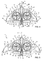
- Each leading edge 10 comprises ( Figures 4 and 5 ):
- Each trailing edge 11 comprises:
- semi-wings 3 are configured as "so-called" delta wings.
- Corresponding edges 42, 45 protrude upwardly from a plane defined by direction A and axis C, so as to form relative winglets 19 which are arranged on respective opposite sides of fuselage 2.
- Each opening 8 is arranged between fuselage 2 and relative winglet 19 parallel to relative axis C and is arranged between edges 10, 11 parallel to direction A.
- Each opening 8 extends about an axis D and is, in the embodiment shown, circular.
- each opening 8 has an edge 29, circular in the embodiment shown.
- axes B are orthogonal to respective axes D and rotors 4 protrudes from opposite, top and bottom, sides of relative openings 8.
- the thickness of rotors 4 parallel to axes D is less than or equal to the thickness of relative openings 8 parallel to axes D.
- Each semi-wing 3 comprises ( Figure 4 and 5 ):
- convertiplane 1 may be operated:
- body 17 comprises fuselage 2 and V-shaped tail 7 and openings 8.
- Body 17 is bounded by stretches 41, stretches 43, 44 and by a pair of walls 32 which lies on a plane orthogonal to axis C.
- the cross section of body 17 taken in a plane orthogonal to axis C comprises a pair of airfoils 60, 65 ( Figure 7 ).
- Airfoil 60 is bounded between a leading edge 10 and a forward portion 47 of edge 29 along direction A.
- Airfoil 60 comprises a topside 61 and a bottom side 62 which join edge 10 and forward portion 47.
- Airfoil 60 extends symmetrically about a rectilinear chord 63 which joins edge 11 and forward portion 47.
- Topside and bottom side 61, 62 are, in the embodiment shown, both convex.
- Airfoil 65 is bounded between a rearward portion 48 of edge 29 and trailing edge 11 along direction A.
- Airfoil 65 comprises a topside 66 and a bottom side 67 which join rearward portion 48 and edge 11.
- Airfoil 65 extends symmetrically about a rectilinear chord 68 which joins edge 11 and forward portion 47.
- Topside and bottom side 65, 66 are, in the embodiment shown, both convex.
- Each wing 18 comprises relative winglet 19 and is bounded by relative stretches 42, 45 on opposite sides.
- Each wing 18 is also bounded by a wall 33 on the opposite side of relative winglet 19.
- Wall 33 of each wing 18 is detachably connected to a relative wall 32 of body 17.
- Each wing 18 is, in particular, backward swept to provide roll stability and reducing wing span for obtaining a given amount of lift.
- Convertiplane 1 also comprises pair of elevons 40 which are arranged on respective stretches 45 and on respective sides of V-shaped tail 7.
- Elevons 40 are hinged to body 17 about an axis H parallel to axis C. In this way, elevons 40 may move upwardly and downwardly relative to body 17 for controlling the pitch and the roll during horizontal flight.
- Each rotor 4 comprises:
- shroud 20 and spokes 30 rotate integrally with blades 27 of each rotor 4 about relative axis C, when convertiplane 1 moves from helicopter and aeroplane mode and vice-versa.
- shroud 20 and spokes 30 are fixed relative to axis B of each rotor 4.
- each shroud 20 extends about relative axis B and has a thickness about a relative axis E orthogonal to relative axis B ( Figures 9 and 10 ).
- Each shroud 20 comprises:
- the cross section of shroud 20 taken in the plane defined by relative axes E, B is configured as an airfoil 25.
- topside 23 and bottom side 24 are antisymmetrical relative to a chord 26 which joins leading and trailing edges 21, 22.
- topside 23 and bottom side 24 are convex.
- rotors 4 about relative axes may tilt independently of each other.
- convertiplane 1 comprises:
- Each actuator 52 comprises, in turn,
- Each actuator 52 also comprises a control unit 51 for controlling the movement of ram 54 parallel to direction A.
- Control units 51 are, in turn, controlled by flight control system 49 on the basis of a plurality of flight and mission parameters.
- the movement of ram 54 relative to fixed part 53 is caused by an electric motor (not-shown).
- each actuator 52 comprises a bar 59 which extends parallel to relative axis C.
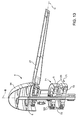
- Bar 59 of each actuator 52 comprises ( Figures 11 and 12 ):
- convertiplane 1 comprises a plurality of connecting elements 92 (only one of which is shown in Figure 12 ) for connecting relative spokes 30 to shroud 20.
- each connecting element 92 comprises a pair of walls 94 fitted to relative spoke 30, and a central portion 95 fitted to a peripheral portion of shroud 20 and coupled with end 91 of bar 59.
- each end 91 and corresponding central portion 95 are coupled by using a splined fitting.
- central portions 95 and ends 91 of bars 59 are partially housed within a cavity defined by shroud 20 ( Figure 12 ).
- each actuator 52 may tilt relative rotor 4 towards end 15 or towards end 16.
- each actuator 52 may tilt relative rotor 4 forward or rearwards relative to axis D.
- convertiplane 1 comprises an electrical power storage device 70; and two pairs of electric machines 71.
- Each electric machine 71 comprises, in turn, a stator 72 electrically connected to storage device 70, and a rotor 73 connected to shaft 6 of relative rotor 4.
- Each electric machine 71 may be operated as:
- rotors 73 are directly connected to shafts 6.
- electric machines 71 when operated as electric motors, they are fed with electrical current by storage device 70.
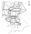
- stator 72 of each electric machine 71 is fitted within housing 5 of relative rotor 4; and rotor 73 of each electric machine 71 is rotatably supported by stator 72 ( Figure 13 ).
- Stator 72 of each electric machine 71 comprises an annular body 120 elongated along relative axes B and defining a plurality of angularly-spaced seats 121.
- seats 121 of each electric machine 71 extend radially relative to respective axis B.
- Stator 72 also comprises a magnetic core 79 which defines a helical slot 78 (not shown in Figure 13 but only in Figure 14 ).
- Core 79 is housed within body 120 and slot 78 is annular relative to axis B.
- Rotor 73 of each electric machine 71 comprises a pair of annular plates arranged on relative opposite axial sides of relative stator 72.
- Electric machines 71 are, in the embodiment shown, axial flux brushless electric machines, i.e. of the type that generates a magnetic flux predominantly extending about axis B.
- Each electric machine 71 also comprises:
- Permanent magnets 76 of each electric machine 71 are angularly equi-spaced about relative axis B.
- Electric machines 71 of each rotor 4 are arranged in series in relation to shaft 6.
- the overall torque to which shaft 6 is subjected about axis B equals the sum of torques exerted by each electric motor 71.
- Coils 75 are electrically connected to storage device 70 by using wires.
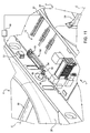
- Storage device 70 may comprise ( Figures 15 and 16 ):
- internal combustion engine 83 recharges hybrid battery 82.
- internal combustion engine 83 is a Diesel engine and comprises a tank 84.
- Convertiplane 1 also comprises:
- Storage device 70 is, in the embodiment shown, a Li-Ion battery.
- Convertiplane 1 also comprises a motor controller 130 ( Figures 15 and 16 ) which receives electrical power from storage device 70 and regulates the power input into electrical machines 71 to control the motion of shafts 6 of rotors 4.
- motor controller 130 is fed by storage device 70 with a continuous current, converts this continuous current into alternate current and feeds electrical machines 71 with alternate current.
- Electric machines 71 may also be operated as an electrical generator during a braking phase of relative shaft 6. In this condition, electrical machines 71 generate electrical current which is stored within battery 81 or battery 82. In other words, electrical machines 71, when operated as an electrical generator, define braking means for braking shafts 6 of relative rotors 4.
- convertiplane 1 may be arranged in the aeroplane mode, after that the landing has been completed.
- electrical machines 71 are operated as electrical generator and generate electrical current which is stored within storage device 70.
- Actuators 52 and battery 81 (or 82) are arranged in portion 13 of fuselage 2.
- Fuselage 2 may house a payload pallet and/or a sensor package.
- Convertiplane 1 also comprises, for each rotor 4, three variable-length actuators 100 which are interposed between housing 5 and relative blades 27 ( Figure 17 ).
- each blade 27 (only schematically shown in Figure 17 ) extends along a relative axis G and is connected to hub 28 by a relative root connecting element 99.
- Each blade 27 comprises a C-shaped appendix 101 which is eccentric relative to respective axis G.
- Each actuator 100 has a first end 102 connected to housing 5 and a second end 103 connected to appendix 101 of relative blade 27.
- End 103 of each actuator 100 may also slide relative to end 102.
- actuators 100 cause the rotation of relative blades 27 about relative axis G.
- each blade 27 is varied.
- actuators 100 may both vary:
- Each actuator 100 may also be used for exerting a given force onto relative blade 27, so as to suppress the vibration of this blade 27.
- actuators 100 are electromechanical.
- convertiplane 1 The operation of convertiplane 1 is described starting from a situation in which convertiplane 1 is operated in the helicopter mode and wings 18 are connected to body 17, which is formed by fuselage 2 and semi-wings 3.
- This configuration is typical of the taking off and/or the landing of convertiplane 1.
- Wings 18 are connected to body 17 when an increased value of lift is required.
- axes B are orthogonal to direction A and parallel to axes D.
- rotors 4 and relative shrouds 20 are fully contained within relative openings 8.
- the thickness of rotors 4 and shrouds 20 is contained within the size of relative openings 8 parallel to corresponding axes D.
- Rotors 4 rotate about relative axes C in opposite direction relative to each other, so that the torques exerted by rotors 4 on convertiplane 1 are balanced.
- shaft 6 of each rotor 4 is driven in rotation about relative axis B by relative each electric machines 71 which are operated, in this case, as electric motors.
- coils 75 are fed with alternate current by storage device 70 and generate a variable magnetic flux on permanent magnets 76.
- Actuators 100 are used for both:
- convertiplane 1 When convertiplane 1 is operated in the helicopter mode, the yawing is controlled by tilting one rotor 4 towards end 15 of fuselage 2 and other rotor 4 towards end 16 of fuselage 2 ( Figure 18 ).
- rotors 4 generate respective forces parallel to direction A which are equal and opposite to each other. As a result, rotor 4 may yaw.
- flight control system 49 control actuators 52 which tilt relative rotors 4 about relative axes C and independently of each other.
- Each control unit 51 controls the sliding of ram 54 parallel to direction A.
- actuators 52 tilt rotors 4 and relative shrouds 20 about relative axes C and towards end 15.
- axes B are firstly slightly inclined relative to axes D ( Figure 3 ) and then are arranged substantially parallel to direction A ( Figure 1 ).
- convertiplane 1 flies, when operated in the aeroplane mode, with direction A slightly inclined relative to a horizontal plane, so that air current defines a not null angle with chords 39, 63, 68 of respective airfoils 36, 60, 65.
- the majority of the lift is provided by wings 18.
- the remaining part of the lift is provided by fuselage 2 and shrouds 20 which duct relative rotors 4.
- Winglets 19 increase the overall aerodynamic efficiency of convertiplane 1.
- elevons 40 may be controlled independently of each other.
- V-shaped tail 7 ensures longitudinal stability in the horizontal flight, thanks to its not-shown customary movable vertical surfaces.
- Rotors 4 can be braked by operating electrical machines 71 as alternate current electrical generator, instead of electric motor.
- Convertiplane 1 can move rearwards, by tilting both rotors 4 towards end 16, without varying the cyclical pitch of blades 27.
- a low-speed transition between the helicopter mode and the aircraft mode may be achieved by tilting rotors 4 towards end 15 or end 16, without varying the cyclical pitch of blades 27. In this transition, fuselage 2 is kept level.
- electrical machines 71 are operated as electrical power generators which re-charge storage device 70.
- rotors 4 may be tilted independently of each other about relative axes C.
- convertiplane 1 when convertediplane 1 is operated as an helicopter, it is possible to generate a yawing moment without varying the collective pitch of blades 27 of rotors 4.
- the yawing may be easily controlled by tilting one rotor 4 forwards (i.e. towards end 15) and the other rotor 4 rearwards (i.e. towards end 16) for the same angle relative to axis D ( Figure 18 ).
- the yawing of convertiplane 1 may be achieved without intervening on the cyclic control of blades 27 of rotors 4.
- the shafts 6 are subjected to reduced control moments and, therefore, to reduced stress, when compared with the solution described in the introductory part of the present description.
- the yaw moment available to convertiplane 1 is increased by the possibility of tilting one rotor 4 towards end 15 and the other rotor 4 towards end 16.
- the yawing moment reaches a maximum value, which is equal to the thrust of each rotor 4 multiplied by the distance between axes C.
- rotors 4 may tilt about relative axes C rearwards - i.e. towards end 16 -, starting from the helicopter mode.
- convertiplane 1 can move rearwards, without intervening on the cyclic control of blades 27 of rotors 4.
- the forward (or backward) low-speed transition between helicopter and aeroplane mode may be carried out by simply tilting both rotors 4 about relative axes C and towards end 15 (or end 16).
- fuselage 2 is kept level.
- shafts 6 are subjected to reduced control moments and, therefore, to reduced stress, when compared with the solution described in the introductory part of the present description.
Landscapes
- Engineering & Computer Science (AREA)
- Aviation & Aerospace Engineering (AREA)
- Mechanical Engineering (AREA)
- Automation & Control Theory (AREA)
- Toys (AREA)
- Transmission Devices (AREA)
Priority Applications (6)
| Application Number | Priority Date | Filing Date | Title |
|---|---|---|---|
| EP11425210.9A EP2551193B1 (fr) | 2011-07-29 | 2011-07-29 | Avion convertible |
| RU2012132335/11A RU2012132335A (ru) | 2011-07-29 | 2012-07-27 | Конвертоплан |
| JP2012167213A JP2013032146A (ja) | 2011-07-29 | 2012-07-27 | 転換式航空機 |
| US13/560,219 US8777150B2 (en) | 2011-07-29 | 2012-07-27 | Convertiplane |
| CN2012102668583A CN102897315A (zh) | 2011-07-29 | 2012-07-30 | 垂直升降飞机 |
| KR1020120083541A KR101958246B1 (ko) | 2011-07-29 | 2012-07-30 | 전환식 항공기 |
Applications Claiming Priority (1)
| Application Number | Priority Date | Filing Date | Title |
|---|---|---|---|
| EP11425210.9A EP2551193B1 (fr) | 2011-07-29 | 2011-07-29 | Avion convertible |
Publications (2)
| Publication Number | Publication Date |
|---|---|
| EP2551193A1 true EP2551193A1 (fr) | 2013-01-30 |
| EP2551193B1 EP2551193B1 (fr) | 2016-04-13 |
Family
ID=44925466
Family Applications (1)
| Application Number | Title | Priority Date | Filing Date |
|---|---|---|---|
| EP11425210.9A Active EP2551193B1 (fr) | 2011-07-29 | 2011-07-29 | Avion convertible |
Country Status (6)
| Country | Link |
|---|---|
| US (1) | US8777150B2 (fr) |
| EP (1) | EP2551193B1 (fr) |
| JP (1) | JP2013032146A (fr) |
| KR (1) | KR101958246B1 (fr) |
| CN (1) | CN102897315A (fr) |
| RU (1) | RU2012132335A (fr) |
Cited By (16)
| Publication number | Priority date | Publication date | Assignee | Title |
|---|---|---|---|---|
| WO2015189684A1 (fr) * | 2014-06-12 | 2015-12-17 | BERMOND, Gérome | Aéronef convertible à aile basculante |
| EP3184425A1 (fr) | 2015-12-21 | 2017-06-28 | AIRBUS HELICOPTERS DEUTSCHLAND GmbH | Aéronef à multirotor |
| EP3354560A1 (fr) * | 2017-01-26 | 2018-08-01 | AIRBUS HELICOPTERS DEUTSCHLAND GmbH | Unité de production de poussée avec au moins deux ensembles rotor et un carénage |
| EP3354566A1 (fr) | 2017-01-26 | 2018-08-01 | AIRBUS HELICOPTERS DEUTSCHLAND GmbH | Unité de propulsion avec deux rotors et un carénage |
| EP3366582A1 (fr) | 2017-02-28 | 2018-08-29 | AIRBUS HELICOPTERS DEUTSCHLAND GmbH | Aéronef multirotor ayant une cellule et un agencement d'unités de production de poussée |
| EP3366586A1 (fr) | 2017-02-27 | 2018-08-29 | AIRBUS HELICOPTERS DEUTSCHLAND GmbH | Unité de production de poussée avec au moins deux ensembles de rotor et un bandage |
| WO2018232430A1 (fr) * | 2017-06-22 | 2018-12-27 | Werner Holzer | Cadre de protection d'hélice pivotant à hélices intégrées à entraînement électrique |
| EP3470332A1 (fr) | 2017-10-13 | 2019-04-17 | AIRBUS HELICOPTERS DEUTSCHLAND GmbH | Aéronef multirotor ayant une cellule et au moins une aile |
| EP3483064A1 (fr) * | 2017-11-13 | 2019-05-15 | Bell Helicopter Textron Inc. | Conduit segmenté pour rotors orientables inclinables |
| EP3581490A1 (fr) | 2018-06-13 | 2019-12-18 | AIRBUS HELICOPTERS DEUTSCHLAND GmbH | Aéronef multirotor avec une unité de production de poussée comprenant un bandage à aérodynamisme optimisé |
| EP3656669A1 (fr) | 2018-11-26 | 2020-05-27 | AIRBUS HELICOPTERS DEUTSCHLAND GmbH | Aéronef multirotor à décollage et atterrissage verticaux comportant au moins huit unités de production de poussée |
| EP3702276A1 (fr) | 2019-02-27 | 2020-09-02 | AIRBUS HELICOPTERS DEUTSCHLAND GmbH | Aéronef multirotor à aile jointe avec des capacités de décollage et atterrissage verticaux (adav) |
| EP3702277A1 (fr) | 2019-02-27 | 2020-09-02 | AIRBUS HELICOPTERS DEUTSCHLAND GmbH | Aéronef multirotor adapté pour décollage et atterrissage verticaux (adav) |
| CN112722260A (zh) * | 2021-01-19 | 2021-04-30 | 西北工业大学 | 一种自适应鼓包增升装置 |
| US11242139B2 (en) * | 2019-12-31 | 2022-02-08 | Textron Innovations Inc. | Spindle to primary duct stator attachment |
| US11634233B2 (en) * | 2020-06-22 | 2023-04-25 | Textron Innovations Inc. | Distributed battery bank for ducted-rotor aircraft |
Families Citing this family (37)
| Publication number | Priority date | Publication date | Assignee | Title |
|---|---|---|---|---|
| US20150274289A1 (en) * | 2014-03-31 | 2015-10-01 | The Boeing Corporation | Vertically landing aircraft |
| WO2016018486A2 (fr) | 2014-05-07 | 2016-02-04 | XTI Aircraft Company | Aéronef à décollage et atterrissage verticaux |
| USD741247S1 (en) * | 2014-06-02 | 2015-10-20 | XTI Aircraft Company | VTOL aircraft |
| CN105292444A (zh) * | 2014-07-08 | 2016-02-03 | 吴建伟 | 一种垂直起降飞行器 |
| KR101693299B1 (ko) * | 2014-10-28 | 2017-01-06 | 주식회사 류테크 | 비행체의 로터헤드 및 무인헬기 |
| KR101666777B1 (ko) * | 2014-10-28 | 2016-10-17 | 주식회사 두레텍 | 회전익 구조체 및 비행 방법 |
| CN104742673A (zh) * | 2015-03-09 | 2015-07-01 | 陆华扬 | 水陆两栖空天直升机 |
| CN106184692A (zh) * | 2015-04-30 | 2016-12-07 | 郑州航空工业管理学院 | 一种可拆装倾转动力的飞翼式复合升力飞艇 |
| JP6435991B2 (ja) * | 2015-05-28 | 2018-12-12 | 株式会社村田製作所 | 電動式航空機 |
| US11034443B2 (en) * | 2015-06-12 | 2021-06-15 | Sunlight Aerospace Inc. | Modular aircraft assembly for airborne and ground transport |
| USD772756S1 (en) * | 2015-09-03 | 2016-11-29 | Neva Aerospaces Limited | Drone |
| CN105346715A (zh) * | 2015-09-29 | 2016-02-24 | 上海圣尧智能科技有限公司 | 一种垂直起降无人机 |
| CN105197230A (zh) * | 2015-10-30 | 2015-12-30 | 佛山市神风航空科技有限公司 | 一种双旋翼飞机 |
| US10926874B2 (en) * | 2016-01-15 | 2021-02-23 | Aurora Flight Sciences Corporation | Hybrid propulsion vertical take-off and landing aircraft |
| EP3366585A4 (fr) * | 2016-02-26 | 2019-07-31 | IHI Corporation | Aéronef à décollage et atterrissage verticaux |
| RU2629473C1 (ru) * | 2016-05-04 | 2017-08-29 | Дмитрий Сергеевич Дуров | Беспилотный конвертоплан с канальными винтами |
| US10040548B2 (en) | 2016-06-28 | 2018-08-07 | Saeid A. ALZAHRANI | Multi-mode aerial vehicle |
| US10293932B2 (en) | 2016-06-28 | 2019-05-21 | Saeid A. ALZAHRANI | Multi-mode unmanned aerial vehicle |
| US10384774B2 (en) | 2016-09-08 | 2019-08-20 | General Electric Company | Tiltrotor propulsion system for an aircraft |
| US10392106B2 (en) | 2016-09-08 | 2019-08-27 | General Electric Company | Tiltrotor propulsion system for an aircraft |
| US10384773B2 (en) | 2016-09-08 | 2019-08-20 | General Electric Company | Tiltrotor propulsion system for an aircraft |
| US10252797B2 (en) | 2016-09-08 | 2019-04-09 | General Electric Company | Tiltrotor propulsion system for an aircraft |
| KR102353513B1 (ko) * | 2017-03-16 | 2022-01-20 | 주식회사 히타치엘지 데이터 스토리지 코리아 | 회전 거리 측정 장치 |
| CN107128489A (zh) * | 2017-05-10 | 2017-09-05 | 优飞科技(苏州)有限公司 | 一种油电混合的垂直起降固定翼飞机 |
| US10313592B1 (en) * | 2017-05-30 | 2019-06-04 | Vance Burberry | Airfoil payload stabilizer |
| US20190004403A1 (en) * | 2017-05-30 | 2019-01-03 | Vance Burberry | Contoured Airfoil Payload Stabilizer |
| CN206856999U (zh) * | 2017-06-22 | 2018-01-09 | 付晓杰 | 旋翼翼尖融合升力飞环装置 |
| US10737797B2 (en) * | 2017-07-21 | 2020-08-11 | General Electric Company | Vertical takeoff and landing aircraft |
| US11724801B2 (en) | 2017-11-03 | 2023-08-15 | Textron Systems Corporation | VTOL aircraft having fixed-wing and rotorcraft configurations |
| CN108176062B (zh) * | 2017-12-28 | 2019-03-29 | 聂梓蕴 | 一种飞行状态可转换的航模 |
| CN108263594B (zh) * | 2018-01-31 | 2019-05-10 | 曹蔚萌 | 一种无叶风扇动力垂直起降无人机 |
| EP3587259B1 (fr) * | 2018-06-28 | 2022-08-10 | Leonardo S.p.A. | Modèle d'assise à l'arrière et procédé de commande associé |
| CN109353500A (zh) * | 2018-11-08 | 2019-02-19 | 南京航空航天大学 | 一种加装水翼的多栖飞行器 |
| KR20220137029A (ko) | 2020-02-10 | 2022-10-11 | 위스크 에어로 엘엘씨 | 푸셔 프로펠러를 가진 항공기 |
| US11643195B2 (en) * | 2020-05-19 | 2023-05-09 | Textron Innovations Inc. | Low-drag blade tip |
| US20210362849A1 (en) * | 2020-05-19 | 2021-11-25 | Archer Aviation, Inc. | Vertical take-off and landing aircraft |
| US11919631B2 (en) | 2021-02-08 | 2024-03-05 | Archer Aviation, Inc. | Vertical take-off and landing aircraft with aft rotor tilting |
Citations (4)
| Publication number | Priority date | Publication date | Assignee | Title |
|---|---|---|---|---|
| US3335977A (en) * | 1965-06-16 | 1967-08-15 | Ludwig F Meditz | Convertiplane |
| EP1057724A2 (fr) | 1999-06-02 | 2000-12-06 | Agusta S.p.A. | Aéronef à rotor basculant |
| US6220545B1 (en) | 1999-08-06 | 2001-04-24 | Bell Helicopter Textron Inc. | Method and apparatus for sensing preload in a tilt rotor downstop |
| US20090256026A1 (en) | 2008-04-11 | 2009-10-15 | Karem Aircraft, Inc. | Tilt Actuation for a Rotorcraft |
Family Cites Families (15)
| Publication number | Priority date | Publication date | Assignee | Title |
|---|---|---|---|---|
| US2620888A (en) * | 1947-03-10 | 1952-12-09 | Harold T Avery | Blade tracking mechanism for lifting rotors |
| US2708081A (en) * | 1950-09-11 | 1955-05-10 | Black John Oliver | Convertible aircraft structure |
| US2991026A (en) * | 1956-06-28 | 1961-07-04 | Doak Aircraft Co Inc | Aircraft flight control system |
| US3039719A (en) * | 1956-11-16 | 1962-06-19 | Haviland H Platt | Vertical take-off airplane |
| US2974900A (en) * | 1959-03-11 | 1961-03-14 | Doak Aircraft Co Inc | Aircraft flight control system |
| US3061242A (en) * | 1960-09-23 | 1962-10-30 | Bell Aerospace Corp | Automatic control apparatus |
| US3284027A (en) * | 1964-01-09 | 1966-11-08 | Nord Aviation | Vtol aircraft having freely pivoted propulsion means |
| US3360217A (en) * | 1965-05-26 | 1967-12-26 | John C Trotter | Duct rotation system for vtol aircraft |
| DE3929886A1 (de) * | 1989-09-08 | 1991-03-28 | Dornier Conrado | Flugzeug mit um eine querachse kippbaren triebwerksgondeln |
| JP2003137192A (ja) * | 2001-10-31 | 2003-05-14 | Mitsubishi Heavy Ind Ltd | 垂直離着陸機 |
| CN1907806A (zh) * | 2005-08-02 | 2007-02-07 | 韩培洲 | 前旋翼倾转式垂直起落飞机 |
| US8152096B2 (en) * | 2005-10-18 | 2012-04-10 | Smith Frick A | Apparatus and method for vertical take-off and landing aircraft |
| US7874513B1 (en) * | 2005-10-18 | 2011-01-25 | Smith Frick A | Apparatus and method for vertical take-off and landing aircraft |
| US8016226B1 (en) * | 2007-07-10 | 2011-09-13 | Wood Victor A | Vertical take off and landing aircraft system with energy recapture technology |
| PL2551190T3 (pl) * | 2011-07-29 | 2014-04-30 | Agustawestland Spa | Zmiennopłat |
-
2011
- 2011-07-29 EP EP11425210.9A patent/EP2551193B1/fr active Active
-
2012
- 2012-07-27 JP JP2012167213A patent/JP2013032146A/ja not_active Ceased
- 2012-07-27 US US13/560,219 patent/US8777150B2/en active Active
- 2012-07-27 RU RU2012132335/11A patent/RU2012132335A/ru not_active Application Discontinuation
- 2012-07-30 KR KR1020120083541A patent/KR101958246B1/ko active IP Right Grant
- 2012-07-30 CN CN2012102668583A patent/CN102897315A/zh active Pending
Patent Citations (4)
| Publication number | Priority date | Publication date | Assignee | Title |
|---|---|---|---|---|
| US3335977A (en) * | 1965-06-16 | 1967-08-15 | Ludwig F Meditz | Convertiplane |
| EP1057724A2 (fr) | 1999-06-02 | 2000-12-06 | Agusta S.p.A. | Aéronef à rotor basculant |
| US6220545B1 (en) | 1999-08-06 | 2001-04-24 | Bell Helicopter Textron Inc. | Method and apparatus for sensing preload in a tilt rotor downstop |
| US20090256026A1 (en) | 2008-04-11 | 2009-10-15 | Karem Aircraft, Inc. | Tilt Actuation for a Rotorcraft |
Cited By (32)
| Publication number | Priority date | Publication date | Assignee | Title |
|---|---|---|---|---|
| FR3022217A1 (fr) * | 2014-06-12 | 2015-12-18 | Bermond Gerome | Aeronef convertible a aile basculante |
| WO2015189684A1 (fr) * | 2014-06-12 | 2015-12-17 | BERMOND, Gérome | Aéronef convertible à aile basculante |
| EP3184425A1 (fr) | 2015-12-21 | 2017-06-28 | AIRBUS HELICOPTERS DEUTSCHLAND GmbH | Aéronef à multirotor |
| US11052998B2 (en) | 2015-12-21 | 2021-07-06 | Airbus Helicopters Deutschland GmbH | Multirotor electric aircraft with redundant security architecture |
| US10737766B2 (en) | 2017-01-26 | 2020-08-11 | Airbus Helicopters Deutschland GmbH | Thrust producing unit with at least two rotor assemblies and a shrouding |
| EP3354560A1 (fr) * | 2017-01-26 | 2018-08-01 | AIRBUS HELICOPTERS DEUTSCHLAND GmbH | Unité de production de poussée avec au moins deux ensembles rotor et un carénage |
| EP3354559A1 (fr) | 2017-01-26 | 2018-08-01 | AIRBUS HELICOPTERS DEUTSCHLAND GmbH | Unité de production de poussée avec au moins deux ensembles rotor et un carénage |
| EP3354566A1 (fr) | 2017-01-26 | 2018-08-01 | AIRBUS HELICOPTERS DEUTSCHLAND GmbH | Unité de propulsion avec deux rotors et un carénage |
| EP3366586A1 (fr) | 2017-02-27 | 2018-08-29 | AIRBUS HELICOPTERS DEUTSCHLAND GmbH | Unité de production de poussée avec au moins deux ensembles de rotor et un bandage |
| US11220325B2 (en) | 2017-02-27 | 2022-01-11 | Airbus Helicopters Deutschland GmbH | Thrust producing unit with at least two rotor assemblies and a shrouding |
| EP3366582A1 (fr) | 2017-02-28 | 2018-08-29 | AIRBUS HELICOPTERS DEUTSCHLAND GmbH | Aéronef multirotor ayant une cellule et un agencement d'unités de production de poussée |
| US10933987B2 (en) | 2017-02-28 | 2021-03-02 | Airbus Helicopters Deutschland GmbH | Multirotor aircraft with an airframe and a thrust producing units arrangement |
| WO2018232430A1 (fr) * | 2017-06-22 | 2018-12-27 | Werner Holzer | Cadre de protection d'hélice pivotant à hélices intégrées à entraînement électrique |
| US10836475B2 (en) | 2017-10-13 | 2020-11-17 | Airbus Helicopters Deutschland GmbH | Multirotor aircraft with an airframe and at least one wing |
| EP3470332A1 (fr) | 2017-10-13 | 2019-04-17 | AIRBUS HELICOPTERS DEUTSCHLAND GmbH | Aéronef multirotor ayant une cellule et au moins une aile |
| EP3483064A1 (fr) * | 2017-11-13 | 2019-05-15 | Bell Helicopter Textron Inc. | Conduit segmenté pour rotors orientables inclinables |
| US20190144107A1 (en) * | 2017-11-13 | 2019-05-16 | Bell Helicopter Textron Inc. | Segmented Duct for Tilting Proprotors |
| US10988245B2 (en) * | 2017-11-13 | 2021-04-27 | Bell Textron Inc. | Segmented duct for tilting proprotors |
| EP3581490A1 (fr) | 2018-06-13 | 2019-12-18 | AIRBUS HELICOPTERS DEUTSCHLAND GmbH | Aéronef multirotor avec une unité de production de poussée comprenant un bandage à aérodynamisme optimisé |
| EP3581491A1 (fr) | 2018-06-13 | 2019-12-18 | AIRBUS HELICOPTERS DEUTSCHLAND GmbH | Aéronef multirotor avec une unité de production de poussée comprenant un bandage à aérodynamisme optimisé |
| US10974815B2 (en) | 2018-06-13 | 2021-04-13 | Airbus Helicopters Deutschland GmbH | Multirotor aircraft with a thrust producing unit that comprises an aerodynamically optimized shrouding |
| US11465733B2 (en) | 2018-06-13 | 2022-10-11 | Airbus Helicopters Deutschland GmbH | Multirotor aircraft with a thrust producing unit that comprises an aerodynamically optimized shrouding |
| EP3656669A1 (fr) | 2018-11-26 | 2020-05-27 | AIRBUS HELICOPTERS DEUTSCHLAND GmbH | Aéronef multirotor à décollage et atterrissage verticaux comportant au moins huit unités de production de poussée |
| US11554862B2 (en) | 2018-11-26 | 2023-01-17 | Airbus Helicopters Deutschland GmbH | Vertical take-off and landing multirotor aircraft with at least eight thrust producing units |
| EP3702277A1 (fr) | 2019-02-27 | 2020-09-02 | AIRBUS HELICOPTERS DEUTSCHLAND GmbH | Aéronef multirotor adapté pour décollage et atterrissage verticaux (adav) |
| US10981650B2 (en) | 2019-02-27 | 2021-04-20 | Airbus Helicopters Deutschland GmbH | Multirotor joined-wing aircraft with VTOL capabilities |
| EP3702276A1 (fr) | 2019-02-27 | 2020-09-02 | AIRBUS HELICOPTERS DEUTSCHLAND GmbH | Aéronef multirotor à aile jointe avec des capacités de décollage et atterrissage verticaux (adav) |
| US11691722B2 (en) | 2019-02-27 | 2023-07-04 | Airbus Urban Mobility Gmbh | Multirotor aircraft that is adapted for vertical take-off and landing |
| US11242139B2 (en) * | 2019-12-31 | 2022-02-08 | Textron Innovations Inc. | Spindle to primary duct stator attachment |
| US11634233B2 (en) * | 2020-06-22 | 2023-04-25 | Textron Innovations Inc. | Distributed battery bank for ducted-rotor aircraft |
| CN112722260A (zh) * | 2021-01-19 | 2021-04-30 | 西北工业大学 | 一种自适应鼓包增升装置 |
| CN112722260B (zh) * | 2021-01-19 | 2022-09-09 | 西北工业大学 | 一种自适应鼓包增升装置 |
Also Published As
| Publication number | Publication date |
|---|---|
| EP2551193B1 (fr) | 2016-04-13 |
| RU2012132335A (ru) | 2014-02-10 |
| US8777150B2 (en) | 2014-07-15 |
| CN102897315A (zh) | 2013-01-30 |
| JP2013032146A (ja) | 2013-02-14 |
| US20130026305A1 (en) | 2013-01-31 |
| KR101958246B1 (ko) | 2019-03-14 |
| KR20130014453A (ko) | 2013-02-07 |
Similar Documents
| Publication | Publication Date | Title |
|---|---|---|
| EP2551193B1 (fr) | Avion convertible | |
| EP2551190B1 (fr) | Avion convertible | |
| EP2551198B1 (fr) | Avion convertible | |
| US12006036B2 (en) | Distributed propulsion system | |
| CN106927030B (zh) | 一种油电混合动力多旋翼飞行器及其飞行控制方法 | |
| US10131426B2 (en) | Aircraft capable of vertical take-off | |
| US20190071174A1 (en) | Vertical take off and landing aircraft with four tilting wings and electric motors | |
| CA3099918C (fr) | Propulsion distribuee | |
| US9139298B2 (en) | Rotorcraft control system for rotorcraft with two or more rotor systems | |
| JP2023508614A (ja) | 翼端に位置付けられたプロペラを伴う航空機 | |
| CN113508080A (zh) | 垂直起降载具 |
Legal Events
| Date | Code | Title | Description |
|---|---|---|---|
| PUAI | Public reference made under article 153(3) epc to a published international application that has entered the european phase |
Free format text: ORIGINAL CODE: 0009012 |
|
| 17P | Request for examination filed |
Effective date: 20120412 |
|
| AK | Designated contracting states |
Kind code of ref document: A1 Designated state(s): AL AT BE BG CH CY CZ DE DK EE ES FI FR GB GR HR HU IE IS IT LI LT LU LV MC MK MT NL NO PL PT RO RS SE SI SK SM TR |
|
| AX | Request for extension of the european patent |
Extension state: BA ME |
|
| 17Q | First examination report despatched |
Effective date: 20130404 |
|
| RAP1 | Party data changed (applicant data changed or rights of an application transferred) |
Owner name: AGUSTAWESTLAND S.P.A. |
|
| RAP1 | Party data changed (applicant data changed or rights of an application transferred) |
Owner name: AGUSTAWESTLAND S.P.A. |
|
| GRAP | Despatch of communication of intention to grant a patent |
Free format text: ORIGINAL CODE: EPIDOSNIGR1 |
|
| INTG | Intention to grant announced |
Effective date: 20151014 |
|
| GRAS | Grant fee paid |
Free format text: ORIGINAL CODE: EPIDOSNIGR3 |
|
| GRAA | (expected) grant |
Free format text: ORIGINAL CODE: 0009210 |
|
| AK | Designated contracting states |
Kind code of ref document: B1 Designated state(s): AL AT BE BG CH CY CZ DE DK EE ES FI FR GB GR HR HU IE IS IT LI LT LU LV MC MK MT NL NO PL PT RO RS SE SI SK SM TR |
|
| REG | Reference to a national code |
Ref country code: GB Ref legal event code: FG4D |
|
| REG | Reference to a national code |
Ref country code: AT Ref legal event code: REF Ref document number: 789814 Country of ref document: AT Kind code of ref document: T Effective date: 20160415 Ref country code: CH Ref legal event code: EP |
|
| REG | Reference to a national code |
Ref country code: IE Ref legal event code: FG4D |
|
| REG | Reference to a national code |
Ref country code: DE Ref legal event code: R096 Ref document number: 602011025242 Country of ref document: DE |
|
| REG | Reference to a national code |
Ref country code: FR Ref legal event code: PLFP Year of fee payment: 6 |
|
| REG | Reference to a national code |
Ref country code: LT Ref legal event code: MG4D |
|
| REG | Reference to a national code |
Ref country code: AT Ref legal event code: MK05 Ref document number: 789814 Country of ref document: AT Kind code of ref document: T Effective date: 20160413 |
|
| REG | Reference to a national code |
Ref country code: NL Ref legal event code: MP Effective date: 20160413 |
|
| PG25 | Lapsed in a contracting state [announced via postgrant information from national office to epo] |
Ref country code: NO Free format text: LAPSE BECAUSE OF FAILURE TO SUBMIT A TRANSLATION OF THE DESCRIPTION OR TO PAY THE FEE WITHIN THE PRESCRIBED TIME-LIMIT Effective date: 20160713 Ref country code: LT Free format text: LAPSE BECAUSE OF FAILURE TO SUBMIT A TRANSLATION OF THE DESCRIPTION OR TO PAY THE FEE WITHIN THE PRESCRIBED TIME-LIMIT Effective date: 20160413 Ref country code: FI Free format text: LAPSE BECAUSE OF FAILURE TO SUBMIT A TRANSLATION OF THE DESCRIPTION OR TO PAY THE FEE WITHIN THE PRESCRIBED TIME-LIMIT Effective date: 20160413 Ref country code: PL Free format text: LAPSE BECAUSE OF FAILURE TO SUBMIT A TRANSLATION OF THE DESCRIPTION OR TO PAY THE FEE WITHIN THE PRESCRIBED TIME-LIMIT Effective date: 20160413 Ref country code: NL Free format text: LAPSE BECAUSE OF FAILURE TO SUBMIT A TRANSLATION OF THE DESCRIPTION OR TO PAY THE FEE WITHIN THE PRESCRIBED TIME-LIMIT Effective date: 20160413 |
|
| PG25 | Lapsed in a contracting state [announced via postgrant information from national office to epo] |
Ref country code: SE Free format text: LAPSE BECAUSE OF FAILURE TO SUBMIT A TRANSLATION OF THE DESCRIPTION OR TO PAY THE FEE WITHIN THE PRESCRIBED TIME-LIMIT Effective date: 20160413 Ref country code: PT Free format text: LAPSE BECAUSE OF FAILURE TO SUBMIT A TRANSLATION OF THE DESCRIPTION OR TO PAY THE FEE WITHIN THE PRESCRIBED TIME-LIMIT Effective date: 20160816 Ref country code: ES Free format text: LAPSE BECAUSE OF FAILURE TO SUBMIT A TRANSLATION OF THE DESCRIPTION OR TO PAY THE FEE WITHIN THE PRESCRIBED TIME-LIMIT Effective date: 20160413 Ref country code: RS Free format text: LAPSE BECAUSE OF FAILURE TO SUBMIT A TRANSLATION OF THE DESCRIPTION OR TO PAY THE FEE WITHIN THE PRESCRIBED TIME-LIMIT Effective date: 20160413 Ref country code: LV Free format text: LAPSE BECAUSE OF FAILURE TO SUBMIT A TRANSLATION OF THE DESCRIPTION OR TO PAY THE FEE WITHIN THE PRESCRIBED TIME-LIMIT Effective date: 20160413 Ref country code: AT Free format text: LAPSE BECAUSE OF FAILURE TO SUBMIT A TRANSLATION OF THE DESCRIPTION OR TO PAY THE FEE WITHIN THE PRESCRIBED TIME-LIMIT Effective date: 20160413 Ref country code: GR Free format text: LAPSE BECAUSE OF FAILURE TO SUBMIT A TRANSLATION OF THE DESCRIPTION OR TO PAY THE FEE WITHIN THE PRESCRIBED TIME-LIMIT Effective date: 20160714 Ref country code: HR Free format text: LAPSE BECAUSE OF FAILURE TO SUBMIT A TRANSLATION OF THE DESCRIPTION OR TO PAY THE FEE WITHIN THE PRESCRIBED TIME-LIMIT Effective date: 20160413 |
|
| PG25 | Lapsed in a contracting state [announced via postgrant information from national office to epo] |
Ref country code: BE Free format text: LAPSE BECAUSE OF FAILURE TO SUBMIT A TRANSLATION OF THE DESCRIPTION OR TO PAY THE FEE WITHIN THE PRESCRIBED TIME-LIMIT Effective date: 20160413 |
|
| REG | Reference to a national code |
Ref country code: DE Ref legal event code: R097 Ref document number: 602011025242 Country of ref document: DE |
|
| PG25 | Lapsed in a contracting state [announced via postgrant information from national office to epo] |
Ref country code: DK Free format text: LAPSE BECAUSE OF FAILURE TO SUBMIT A TRANSLATION OF THE DESCRIPTION OR TO PAY THE FEE WITHIN THE PRESCRIBED TIME-LIMIT Effective date: 20160413 Ref country code: SK Free format text: LAPSE BECAUSE OF FAILURE TO SUBMIT A TRANSLATION OF THE DESCRIPTION OR TO PAY THE FEE WITHIN THE PRESCRIBED TIME-LIMIT Effective date: 20160413 Ref country code: CZ Free format text: LAPSE BECAUSE OF FAILURE TO SUBMIT A TRANSLATION OF THE DESCRIPTION OR TO PAY THE FEE WITHIN THE PRESCRIBED TIME-LIMIT Effective date: 20160413 Ref country code: EE Free format text: LAPSE BECAUSE OF FAILURE TO SUBMIT A TRANSLATION OF THE DESCRIPTION OR TO PAY THE FEE WITHIN THE PRESCRIBED TIME-LIMIT Effective date: 20160413 Ref country code: RO Free format text: LAPSE BECAUSE OF FAILURE TO SUBMIT A TRANSLATION OF THE DESCRIPTION OR TO PAY THE FEE WITHIN THE PRESCRIBED TIME-LIMIT Effective date: 20160413 |
|
| PLBE | No opposition filed within time limit |
Free format text: ORIGINAL CODE: 0009261 |
|
| STAA | Information on the status of an ep patent application or granted ep patent |
Free format text: STATUS: NO OPPOSITION FILED WITHIN TIME LIMIT |
|
| PG25 | Lapsed in a contracting state [announced via postgrant information from national office to epo] |
Ref country code: SM Free format text: LAPSE BECAUSE OF FAILURE TO SUBMIT A TRANSLATION OF THE DESCRIPTION OR TO PAY THE FEE WITHIN THE PRESCRIBED TIME-LIMIT Effective date: 20160413 |
|
| REG | Reference to a national code |
Ref country code: CH Ref legal event code: PL |
|
| 26N | No opposition filed |
Effective date: 20170116 |
|
| PG25 | Lapsed in a contracting state [announced via postgrant information from national office to epo] |
Ref country code: MC Free format text: LAPSE BECAUSE OF FAILURE TO SUBMIT A TRANSLATION OF THE DESCRIPTION OR TO PAY THE FEE WITHIN THE PRESCRIBED TIME-LIMIT Effective date: 20160413 |
|
| PG25 | Lapsed in a contracting state [announced via postgrant information from national office to epo] |
Ref country code: CH Free format text: LAPSE BECAUSE OF NON-PAYMENT OF DUE FEES Effective date: 20160731 Ref country code: LI Free format text: LAPSE BECAUSE OF NON-PAYMENT OF DUE FEES Effective date: 20160731 |
|
| REG | Reference to a national code |
Ref country code: IE Ref legal event code: MM4A |
|
| PG25 | Lapsed in a contracting state [announced via postgrant information from national office to epo] |
Ref country code: SI Free format text: LAPSE BECAUSE OF FAILURE TO SUBMIT A TRANSLATION OF THE DESCRIPTION OR TO PAY THE FEE WITHIN THE PRESCRIBED TIME-LIMIT Effective date: 20160413 |
|
| REG | Reference to a national code |
Ref country code: FR Ref legal event code: PLFP Year of fee payment: 7 |
|
| PG25 | Lapsed in a contracting state [announced via postgrant information from national office to epo] |
Ref country code: IE Free format text: LAPSE BECAUSE OF NON-PAYMENT OF DUE FEES Effective date: 20160729 |
|
| PG25 | Lapsed in a contracting state [announced via postgrant information from national office to epo] |
Ref country code: LU Free format text: LAPSE BECAUSE OF NON-PAYMENT OF DUE FEES Effective date: 20160729 |
|
| PG25 | Lapsed in a contracting state [announced via postgrant information from national office to epo] |
Ref country code: CY Free format text: LAPSE BECAUSE OF FAILURE TO SUBMIT A TRANSLATION OF THE DESCRIPTION OR TO PAY THE FEE WITHIN THE PRESCRIBED TIME-LIMIT Effective date: 20160413 Ref country code: HU Free format text: LAPSE BECAUSE OF FAILURE TO SUBMIT A TRANSLATION OF THE DESCRIPTION OR TO PAY THE FEE WITHIN THE PRESCRIBED TIME-LIMIT; INVALID AB INITIO Effective date: 20110729 |
|
| PG25 | Lapsed in a contracting state [announced via postgrant information from national office to epo] |
Ref country code: IS Free format text: LAPSE BECAUSE OF FAILURE TO SUBMIT A TRANSLATION OF THE DESCRIPTION OR TO PAY THE FEE WITHIN THE PRESCRIBED TIME-LIMIT Effective date: 20160413 Ref country code: TR Free format text: LAPSE BECAUSE OF FAILURE TO SUBMIT A TRANSLATION OF THE DESCRIPTION OR TO PAY THE FEE WITHIN THE PRESCRIBED TIME-LIMIT Effective date: 20160413 Ref country code: MK Free format text: LAPSE BECAUSE OF FAILURE TO SUBMIT A TRANSLATION OF THE DESCRIPTION OR TO PAY THE FEE WITHIN THE PRESCRIBED TIME-LIMIT Effective date: 20160413 Ref country code: MT Free format text: LAPSE BECAUSE OF NON-PAYMENT OF DUE FEES Effective date: 20160731 |
|
| REG | Reference to a national code |
Ref country code: FR Ref legal event code: PLFP Year of fee payment: 8 |
|
| PG25 | Lapsed in a contracting state [announced via postgrant information from national office to epo] |
Ref country code: BG Free format text: LAPSE BECAUSE OF FAILURE TO SUBMIT A TRANSLATION OF THE DESCRIPTION OR TO PAY THE FEE WITHIN THE PRESCRIBED TIME-LIMIT Effective date: 20160413 |
|
| PG25 | Lapsed in a contracting state [announced via postgrant information from national office to epo] |
Ref country code: AL Free format text: LAPSE BECAUSE OF FAILURE TO SUBMIT A TRANSLATION OF THE DESCRIPTION OR TO PAY THE FEE WITHIN THE PRESCRIBED TIME-LIMIT Effective date: 20160413 |
|
| REG | Reference to a national code |
Ref country code: DE Ref legal event code: R082 Ref document number: 602011025242 Country of ref document: DE Representative=s name: TER MEER STEINMEISTER & PARTNER PATENTANWAELTE, DE Ref country code: DE Ref legal event code: R081 Ref document number: 602011025242 Country of ref document: DE Owner name: LEONARDO S.P.A., IT Free format text: FORMER OWNER: AGUSTAWESTLAND S.P.A, ROM, IT |
|
| PGFP | Annual fee paid to national office [announced via postgrant information from national office to epo] |
Ref country code: IT Payment date: 20230706 Year of fee payment: 13 |
|
| P01 | Opt-out of the competence of the unified patent court (upc) registered |
Effective date: 20231005 |
|
| PGFP | Annual fee paid to national office [announced via postgrant information from national office to epo] |
Ref country code: DE Payment date: 20240730 Year of fee payment: 14 |
|
| PGFP | Annual fee paid to national office [announced via postgrant information from national office to epo] |
Ref country code: GB Payment date: 20240724 Year of fee payment: 14 |
|
| PGFP | Annual fee paid to national office [announced via postgrant information from national office to epo] |
Ref country code: FR Payment date: 20240725 Year of fee payment: 14 |