EP2550823B1 - Action temporisée de contrôle de flux dans des communications wcdma à couche de réseau de transport - Google Patents
Action temporisée de contrôle de flux dans des communications wcdma à couche de réseau de transport Download PDFInfo
- Publication number
- EP2550823B1 EP2550823B1 EP11759789.8A EP11759789A EP2550823B1 EP 2550823 B1 EP2550823 B1 EP 2550823B1 EP 11759789 A EP11759789 A EP 11759789A EP 2550823 B1 EP2550823 B1 EP 2550823B1
- Authority
- EP
- European Patent Office
- Prior art keywords
- congestion
- transport network
- flow control
- radio access
- control action
- Prior art date
- Legal status (The legal status is an assumption and is not a legal conclusion. Google has not performed a legal analysis and makes no representation as to the accuracy of the status listed.)
- Active
Links
- 230000009471 action Effects 0.000 title claims description 63
- 238000004891 communication Methods 0.000 title claims description 19
- 230000003111 delayed effect Effects 0.000 title description 9
- 238000001514 detection method Methods 0.000 claims description 51
- 238000000034 method Methods 0.000 claims description 23
- 230000004044 response Effects 0.000 claims description 12
- 238000012544 monitoring process Methods 0.000 claims 1
- 238000004364 calculation method Methods 0.000 description 9
- 238000005516 engineering process Methods 0.000 description 8
- 230000005540 biological transmission Effects 0.000 description 6
- 230000007246 mechanism Effects 0.000 description 4
- 101000741965 Homo sapiens Inactive tyrosine-protein kinase PRAG1 Proteins 0.000 description 2
- 102100038659 Inactive tyrosine-protein kinase PRAG1 Human genes 0.000 description 2
- 235000009421 Myristica fragrans Nutrition 0.000 description 2
- 244000270834 Myristica fragrans Species 0.000 description 2
- 239000000654 additive Substances 0.000 description 2
- 230000000996 additive effect Effects 0.000 description 2
- 230000001413 cellular effect Effects 0.000 description 2
- 238000009432 framing Methods 0.000 description 2
- 238000007493 shaping process Methods 0.000 description 2
- 230000011664 signaling Effects 0.000 description 2
- 230000001360 synchronised effect Effects 0.000 description 2
- 229910000906 Bronze Inorganic materials 0.000 description 1
- BQCADISMDOOEFD-UHFFFAOYSA-N Silver Chemical compound [Ag] BQCADISMDOOEFD-UHFFFAOYSA-N 0.000 description 1
- 230000004931 aggregating effect Effects 0.000 description 1
- 230000009286 beneficial effect Effects 0.000 description 1
- 230000008901 benefit Effects 0.000 description 1
- 239000010974 bronze Substances 0.000 description 1
- 230000010267 cellular communication Effects 0.000 description 1
- KUNSUQLRTQLHQQ-UHFFFAOYSA-N copper tin Chemical compound [Cu].[Sn] KUNSUQLRTQLHQQ-UHFFFAOYSA-N 0.000 description 1
- 230000001934 delay Effects 0.000 description 1
- 238000010586 diagram Methods 0.000 description 1
- 230000000694 effects Effects 0.000 description 1
- PCHJSUWPFVWCPO-UHFFFAOYSA-N gold Chemical compound [Au] PCHJSUWPFVWCPO-UHFFFAOYSA-N 0.000 description 1
- 229910052737 gold Inorganic materials 0.000 description 1
- 239000010931 gold Substances 0.000 description 1
- 238000007726 management method Methods 0.000 description 1
- 229920001690 polydopamine Polymers 0.000 description 1
- 238000000926 separation method Methods 0.000 description 1
- 229910052709 silver Inorganic materials 0.000 description 1
- 239000004332 silver Substances 0.000 description 1
Images


Classifications
-
- H—ELECTRICITY
- H04—ELECTRIC COMMUNICATION TECHNIQUE
- H04W—WIRELESS COMMUNICATION NETWORKS
- H04W8/00—Network data management
- H04W8/02—Processing of mobility data, e.g. registration information at HLR [Home Location Register] or VLR [Visitor Location Register]; Transfer of mobility data, e.g. between HLR, VLR or external networks
- H04W8/04—Registration at HLR or HSS [Home Subscriber Server]
-
- H—ELECTRICITY
- H04—ELECTRIC COMMUNICATION TECHNIQUE
- H04L—TRANSMISSION OF DIGITAL INFORMATION, e.g. TELEGRAPHIC COMMUNICATION
- H04L47/00—Traffic control in data switching networks
- H04L47/10—Flow control; Congestion control
- H04L47/11—Identifying congestion
-
- H—ELECTRICITY
- H04—ELECTRIC COMMUNICATION TECHNIQUE
- H04L—TRANSMISSION OF DIGITAL INFORMATION, e.g. TELEGRAPHIC COMMUNICATION
- H04L47/00—Traffic control in data switching networks
- H04L47/10—Flow control; Congestion control
- H04L47/24—Traffic characterised by specific attributes, e.g. priority or QoS
- H04L47/2441—Traffic characterised by specific attributes, e.g. priority or QoS relying on flow classification, e.g. using integrated services [IntServ]
-
- H—ELECTRICITY
- H04—ELECTRIC COMMUNICATION TECHNIQUE
- H04L—TRANSMISSION OF DIGITAL INFORMATION, e.g. TELEGRAPHIC COMMUNICATION
- H04L47/00—Traffic control in data switching networks
- H04L47/10—Flow control; Congestion control
- H04L47/28—Flow control; Congestion control in relation to timing considerations
-
- H—ELECTRICITY
- H04—ELECTRIC COMMUNICATION TECHNIQUE
- H04W—WIRELESS COMMUNICATION NETWORKS
- H04W28/00—Network traffic management; Network resource management
- H04W28/02—Traffic management, e.g. flow control or congestion control
- H04W28/0247—Traffic management, e.g. flow control or congestion control based on conditions of the access network or the infrastructure network
-
- H—ELECTRICITY
- H04—ELECTRIC COMMUNICATION TECHNIQUE
- H04W—WIRELESS COMMUNICATION NETWORKS
- H04W28/00—Network traffic management; Network resource management
- H04W28/02—Traffic management, e.g. flow control or congestion control
- H04W28/0252—Traffic management, e.g. flow control or congestion control per individual bearer or channel
-
- H—ELECTRICITY
- H04—ELECTRIC COMMUNICATION TECHNIQUE
- H04W—WIRELESS COMMUNICATION NETWORKS
- H04W28/00—Network traffic management; Network resource management
- H04W28/02—Traffic management, e.g. flow control or congestion control
- H04W28/0284—Traffic management, e.g. flow control or congestion control detecting congestion or overload during communication
-
- H—ELECTRICITY
- H04—ELECTRIC COMMUNICATION TECHNIQUE
- H04W—WIRELESS COMMUNICATION NETWORKS
- H04W28/00—Network traffic management; Network resource management
- H04W28/02—Traffic management, e.g. flow control or congestion control
- H04W28/10—Flow control between communication endpoints
- H04W28/12—Flow control between communication endpoints using signalling between network elements
-
- H—ELECTRICITY
- H04—ELECTRIC COMMUNICATION TECHNIQUE
- H04L—TRANSMISSION OF DIGITAL INFORMATION, e.g. TELEGRAPHIC COMMUNICATION
- H04L43/00—Arrangements for monitoring or testing data switching networks
- H04L43/08—Monitoring or testing based on specific metrics, e.g. QoS, energy consumption or environmental parameters
- H04L43/0876—Network utilisation, e.g. volume of load or congestion level
- H04L43/0882—Utilisation of link capacity
Definitions
- the technical field relates to radio communications systems, and more particularly, to detecting congestion in a radio access transport network.
- HSPA High Speed Packet Access
- WCDMA Wideband Code Division Multiple Access
- RAN Wideband Code Division Multiple Access
- FIG 1 illustrates a WCDMA network 10 with one or more user equipments (UEs) 12 communicating with a WCDMA radio access network (WCDMA RAN) over a Uu air interface, and one or more core networks 18 communicate with radio network controllers (RNCs) 16 in the WCDMA RAN over an Iu interface.
- WCDMA RAN is also called Universal Mobile Telecommunications System (UMTS) Terrestrial Radio Access Network (UTRAN).
- UMTS Universal Mobile Telecommunications System
- UTRAN Universal Mobile Telecommunications System
- the WCDMA RAN handles all tasks that relate to radio access control such as radio resource management and handover control.
- the core network connects the access network to one or more external networks (PSTN, Internet, etc.).
- PSTN public switched telephone network
- the user equipment (sometimes called a Mobile Terminal or Mobile Station) 12 is connected to one or more radio base stations (Node Bs) 13 over the WCDMA air interface (Uu).
- Node Bs radio base stations
- One or more base stations are coupled to an RNC 16 over an Iub interface, and the RNCs communicate over an Iur interface.
- RNC radio base stations
- the WCDMA RAN Transport Network transmits data and control information between the Radio Network Controller (RNC) and the Node Bs (Iub interface) or between RNCs (Iur interface).
- RNC Radio Network Controller
- Iub interface the Node Bs
- RNCs Iur interface
- SRNC Serving RNC
- the transport network layer provides data and signaling bearers for the radio network application protocols between RAN nodes and includes transport network control-plane functions for establishing and releasing such bearers when instructed to do so by the radio network layer.
- the first release of the 3GPP specification was called Release 99.
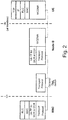
- Figure 2 shows the Release 99 protocol stack at the Iub interface for transferring data streams on common transport channels (CCH) and dedicated transport channels (DCH) to the air interface.
- the acknowledged retransmission mechanism of the radio link control (RLC) protocol ensures reliable transmission of loss-sensitive traffic over the air interface.
- RLC provides three types of service to the upper layers: transparent (no additional protocol information), unacknowledged (delivery not guaranteed), and acknowledged data transfer mode.
- the normal RLC mode for packet-type services is the acknowledged mode, so RLC works in this mode in case of HSPA as well.
- the RLC protocol is used by both signaling radio bearers and radio bearers for packet-switched data services, but not by radio bearers for circuit-switched services.
- RLC Acknowledged Mode which is a Selective Repeat Automatic Repeat-request (SR-ARQ) protocol, provides transport service to upper layers between UE and the RNC.
- RLC AM does not include congestion control functionality because it assumes that RLC Protocol Data Units (PDUs) are transmitted by the Medium Access Control - dedicated (MAC-d) layer according to the available capacity allocated on the air interface Uu and the Transport Network.
- RLC status messages are sent regularly based on preset events and trigger retransmission of all missing PDUs.
- the receiver side detects missing RLC PDUs based on gaps in the PDU sequence numbers.
- the receiver side RLC requests retransmission by sending back a status PDU, informing which PDUs within the receiving window have been acknowledged (ACK) or lost (negative ACK, NACK).
- ACK acknowledged
- NACK negative ACK
- the sender can slide its transmission window (Tx window) if one or more in-sequence frames are acknowledged, so that new PDUs can be sent. If there are NACKs in the status message, the sender retransmits the missing PDUs giving them priority over new ones.
- Several unsuccessful retransmissions of the same PDU trigger an RLC reset, and the whole RLC Tx window is discarded.
- FIG. 2 shows a user plane protocol stack between the RNC and Node B for Release 99.
- the MAC-d protocol forms sets of transport blocks in the air interface and schedules them according to the timing requirements of WCDMA. Each scheduled period, called a transmission time interval (TTI), is 10 ms in length or multiples thereof. Release 99 WCDMA radio connections, or radio access bearers (RAB), have practical bit rate values between 8 and 384 kbps.
- the size of the MAC transport blocks and length of the TTI are RAB-specific.
- the MAC transport blocks are encapsulated into Iub frames according to the Iub user-plane (UP) protocol for CCH or DCH data streams. Each Iub user-plane data stream needs a separate transport network connection between the RNC and Node B. The transport network thus establishes one transport network layer connection for each data stream.
- an optional TNL switch may used for building/aggregating transport networks.
- the WCDMA 3GPP Release 5 extended the WCDMA specification with the High Speed Downlink Packet Access (HSDPA), and Release 6 introduced Enhanced Dedicated Channel (E-DCH), often referred as Enhanced Uplink (EUL) or High Speed Uplink Packet Access (HSUPA).
- HSDPA and HSUPA together are called HSPA.
- HSPA certain parts of radio resource control are moved from the RNC to the Node Bs.
- MIMO multiple input multiple output
- transport network bandwidth can be reserved using admission control for Dedicated Channels (DCHs) traffic in the access transport network
- DCHs Dedicated Channels
- flow corresponds to a logical connection in the radio access transport network that carries data packets associated with a UE connection. Packets associated with a flow are carried using one or more communications channels on a physical link connecting nodes in the transport network. Because bandwidth reservation is not used, congestion may occur in both the Iub transport network and over the air interface. Congestion occurs when the available communications capacity is exceeded by the sum of the current data packet flow rates.
- the TCP protocol layer in the UE and in the uplink server cannot efficiently resolve a congestion situation in the radio access network because RLC AM retransmissions between the RNC and the UE hide congestion situations from TCP.
- Congestion is particularly a problem given the increased air interface capacity provided by HSPA. That increased air interface capacity does not necessarily mean there is increased Iub transport network capacity. Network operators often upgrade the Node Bs first and delay the upgrade of the transport network until there is significant HSPA traffic. In some cases, the cost of Iub transport links is still high, and thus, it is a common scenario that throughput is limited by the capacity available on the Iub transport network links and not by the capacity of the air interface.
- a typical scenario is that the Node B is connected to the RNC through an E1 link of capacity about 2 Mbps, and the available Uu capacity for HSDPA can be significantly larger that this 2 Mbps. So a single UE given good radio conditions can overload the radio transport network (TN). "Bottleneck" transport network links or nodes can therefore be a serious problem.
- TN radio transport network
- TCP "slow start" normally quickly increases a TCP congestion window size to its maximum, and it is kept at that value. Due to RLC retransmissions, TCP does not experience packet loss. In case of transport network congestion, the RLC layer keeps retransmitting lost PDUs until they are successfully received (or until RLC resets). Unfortunately, these retransmissions increase the congestion level, and TCP is only notified about the transport network congestion at a significantly later time. Accordingly, because the RLC layer does not have congestion control functionality and TCP congestion control does not operate efficiently in the transport network, HSPA data packet flow control is necessary. Although fair sharing of radio resources over the Uu air interface is the task of the Uu scheduler in the Node B, the Uu scheduler can not solve the bottleneck problem in the transport network.
- a flow control (FC) mechanism may be introduced in the RNC and/or Node B to regulate each data packet flow.
- An important goal for transport network flow congestion detection and control is to fairly allocate the transport network communication resources (e.g., bit rate) to ongoing data packet flows based on the available link capacity in the transport network.
- the fairness of HSPA flow control depends on the fairness of transport network congestion detection.
- an Additive Increase Multiplicative Decrease (AIMD) type congestion control procedure requires synchronous congestion signals for fair bandwidth sharing. Synchronous congestion signals means that when a transport network link is congested, all the flows using that link need to detect or otherwise be aware of the transport network congestion situation.
- AIMD Additive Increase Multiplicative Decrease
- the patent publication WO2009/058085 discloses a mechanism to resolve the Iub transport network congestion efficiently for HSDPA by dynamic adjustment of the transmit window of the RLC. Further, the patent publication WO2006/075951 , discloses a method for managing an uplink overload or congestion condition between nodes in a radio access network.
- Congestion is detected in a radio access transport network that includes one or more radio network controllers each coupled to one or more radio base stations. Multiple data packet flows are each associated with a mobile radio terminal communication, and each flow is controlled in the radio access transport network by a corresponding flow control entity. Each flow is monitored for congestion in the transport network. A flow control action is determined in response to detected congestion. Performance of the flow control action is delayed for a predetermined delay period before the flow control action may be performed. Delaying flow control action after congestion is detected for that flow allows other affected flows to detect or be notified of the congestion, thereby making congestion detection more fair.
- a flow control action message e.g., decrease the bit rate of a flow affected by the congestion bottleneck
- transmission of the generated flow control action message is delayed for a predetermined delay period.
- the generated flow control action message is then sent so that one or more of the flow control entities may take a flow control action based on the detected congestion.
- a flow control action message may be generated in response to the detected congestion and sent. The receiving entity then waits the predetermined delay period after the generated flow control action message is received before performing a flow control action in response to the flow control action message.
- the detected congestion area may be for example a shared congested communications link in the radio access transport network, a shared congested radio network controller, or a shared congested radio base station.
- delaying performance of the flow control action for the predetermined delay period occurs whenever congestion is detected in the radio access transport network. In another example embodiment, delaying performance of the flow control action for the predetermined delay period occurs only for some but not all of the times when congestion is detected in the radio access transport network In another example embodiment, delaying performance of the flow control action for the predetermined delay period occurs only if the detected congestion is a predetermined type of congestion. In another example embodiment, delaying performance of the flow control action for the predetermined delay period occurs only if the monitored data packet flow is associated with a particular service class.
- the predetermined delay period may include different predetermined delay period values.
- the predetermined delay period may include a first delay associated with detecting a soft type of congestion and a second, shorter delay associated with detecting a hard type of congestion.
- a maximum delay value actually waited in a recent prior time interval may be determined. If the maximum delay value exceeds the predetermined delay period, then the flow control action is performed or a flow control action message is sent without waiting predetermined delay period.
- the detected congestion may be in a downlink direction from radio network controller to radio base station or in an uplink direction from radio base station to radio network controller.
- the congestion detection and notification may be performed in a radio base station, e.g., in the downlink, or in a radio network controller, e.g., in the uplink.
- the technology may be used in any type of cellular radio communications.
- the term mobile radio terminal encompasses any kind of radio communications terminal/device like user equipment (UE), PDAs, cell phones, laptops, etc.
- UE user equipment
- PDAs personal area network
- cell phones cell phones
- laptops etc.
- the data packet flow control technology described in this application may be used for example in a WCDMA based communications system 10 in Figure 1 described above. But those skilled in the art will appreciate that the technology may be used in any radio access transport network where congestion detection and control are useful.
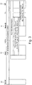
- Figure 3 illustrates protocol layers performing congestion control and/or retransmission in the WCDMA network example.
- TCP retransmission and congestion control is not effective in detecting and fairly implementing congestion control in the transport network. Therefore, transport network congestion detection and control is implemented, e.g., in the RNC and Node B.
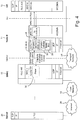
- FIG. 4 shows an example HSPDA protocol stack and flow control architecture that can be used in this non-limiting WCDMA network example.
- a server 22 communicates at the TCP layer with the UE 12 via the internet 20, a core network 18, a serving RNC 16, and a Node B radio base station 14 over corresponding interfaces.
- Each flow-controlled flow has a corresponding logical flow controller implemented in functionality of the Node B and RNC serving that flow. (There may be other flows that are not flow-controlled in the transport network).
- each data packet flow controller is implemented using congestion detection functionality, maximum allowed transport network bit rate determination functionality, and flow shaping functionality for implementing/enforcing that maximum allowed transport network bit rate. While the following description distributes these flow control functionalities to particular nodes and protocol layers for illustration purposes only, the flow control functionalities may be implemented centrally, in some other distribution, or in any other suitable manner.
- the congestion detection functionality 30 receives packets with frame sequence numbers (FSNs) and delay reference times (DRTs) from the RNC 16.
- FSNs frame sequence numbers
- DRTs delay reference times
- the Iub/Iur Framing Protocol E-DCH data frame (DF) contains the user data, the Frame Sequence Number (FSN), the Connection Frame Number (CFN), and Subframe Number.
- FSN and DRT can be used for transport network congestion detection.
- the DRT field contains the value of a DRT reference counter corresponding to when the data frame was sent. The DRT counter may be increased for example every 1ms.
- the congestion detection 30 function analyzes packets for its data packet flow from the RNC and interprets a gap in sequence numbers of arriving packets as "hard” congestion because this gap is likely due to packet loss in the transport network caused by congestion.
- the congestion detection 30 function also measures the variation of the one-way packet delay between RNC and Node B using a time-stamp, e.g., in a DRT field, in some of the received packets. In on example implementation, if this delay starts to increase, probably due to queue build up in the transport network, the condition may be interpreted as "soft” congestion. But if this delay build up is larger than a predetermined threshold, e.g. 60 ms, the condition may be interpreted as "hard” congestion.
- RNC-RNC-A there are two RNCs-RNC-A and RNC-B. Each has its own counter used to provide a time stamp in the DRT field. Assume also each counter is set to zero when started and is incremented every 1 msec. If RNC-B's counter starts 3 seconds after RNC-A's counter, then RNC-B's counter will be zero when RNC-A's counter reaches 3000 msecs.
- both RNC-A and RNC-B send a packet at the same time, e.g., at 6 seconds
- RNC-A inserts 6000 into the DRT field for the packet associated with one flow while RNC-B inserts 3000 into the DRT field of a packet associated with another flow.
- the Node B determines there is a significant difference between the two DRT values and correctly concludes that the two packets are coming from different RNCs.
- the assumption is that flows from the same RNC experience the same or at least similar congestion. So once congestion is detected, the approach described in this paragraph is one example way of determining a group of flows that share the same congestion area.
- Another factor that may be used to detect congestion is to detect the length of the Node B packet queue (PQ) for the flow. If the PQ length is too long, e.g., exceeds a threshold, then a congested condition is detected.
- PQ Node B packet queue
- a congestion controller 38 in the Node B 14 receives detected congestion information from each congestion detection entity 30 associated with flows detected as congested.
- the congestion controller 38 identifies from the detected congestion information provided by the other congestion detection entities 30 which other flows share the same transport network bottleneck (a congested transport network link, a congested RNC, etc.).
- the congestion controller 38 then distributes information concerning the detected congestion to the flow control entities for those identified flows. That way most and preferably all of the flow entities using the congested transport network communications resource (the bottleneck) know about the congestion and can take necessary actions to reduce or avoid the congestion.
- These flow entities should be unaware of the congestion situation because either they detected the congestion themselves or they were informed of the congestion.
- the beneficial result is fair congestion detection which can lead to fair sharing of limited resources.
- the bit rate calculation functionality 32 determines an appropriate maximum allowable transport network bit rate for its data packet flow.
- a slow-start like mechanism may be used to discover a suitable starting maximum allowed bit rate for the flow. If transport network congestion is detected by congestion detection entity 30, then it generates a signal to reduce transport network resource use in the congested area, e.g., reduce bit rate of a flow.
- the bit rate calculation function 32 responds to hard and soft congestion in different ways.
- the bit rate calculation function 32 calculates the current maximum bit rate allowed by the transport network for each flow. For example, that maximum allowed rate may conform with an Additive Increase Multiplicative Decrease (AIMD) property that guarantees convergence to fairness, i.e., the flows converge to an equal share of resources in steady state, assuming no flows join or leave.
- AIMD Additive Increase Multiplicative Decrease
- a maximum bit rate for each flow is maintained. That maximum bit rate is increased (e.g., linearly, additively, etc.) for a flow if there is no reported congestion from congestion detection function 30 for that flow. But if congestion is reported for a flow, then its maximum bit rate typically will be reduced.
- the bit rate might be reduced for example by 50% in the case of hard congestion and for example by 10% in the case of soft congestion.
- a shaper function 36 in the serving RNC 16 may be informed about the new bit rate (or other resource use parameter) through a control frame, e.g., a Capacity Allocation (CA) control frame is shown in Figure 4 .
- the shaper 36 shapes each data packet flow according to its corresponding signaled maximum allowed flow bit rate.
- the Iub Framing Protocol (FP) puts them into Iub Data Frames and sends them to the Node B.
- Each frame contains a Frame Sequence Number (FSN), and some frames contain an absolute value of a Delay Reference Time (DRT). For example, this DRT value may incremented in the RNC every 1 ms.
- FSN Frame Sequence Number
- DRT Delay Reference Time
- TCI transport congestion information
- the RNC sends transport congestion information (TCI) for all flows supported by a Node B.
- TCI transport congestion information
- the RNC sends transport congestion information (TCI) for all flows supported by a Node B.
- TCI transport congestion information
- flows coming from the same Node B are identified based on the DRT values. All flows coming from the same Node B can be informed about congestion using a TCI control frame.
- Another example option relates to downlink transport network bottlenecks already identified in a Node B.
- the TCI includes all EUL flows affected by the same bottleneck.
- the central congestion controller receives the TCI, then all flows coming from the same RNC may be informed about the congestion.
- flow control action in response to congestion detection is preferably delayed.
- transmission of the CA control frame may be delayed for a predetermined time delay.
- predetermined time delay might be 100 ms. Any suitable delay value may be used that enables fair congestion detection.
- the detected buffer levels a measure of transport network delay
- the detected buffer levels grow and more loss events occur for those flows, which makes congestion detection by all of the congestion-affected flows more likely, and thus, congestion detection is more fair. For example, if a congestion detection threshold is almost but not yet exceeded, after waiting for the predetermined delay, that threshold will be exceeded for affected flows and therefore detected with a higher probability.
- the likelihood of the detecting packet loss increases for congestion-affected flows.
- One way of implementing the predetermined delay time is to use a prohibit timer 39 for each congestion-affected flow.
- An example location for the prohibit timers 39 is in the congestion controller 38 as shown in Figure 4 .
- the congestion controller 38 starts the prohibit timer 39 when congestion detection 30 detects congestion for a flow.
- the congestion controller 38 instructs the bit rate calculator 32 for the flow to transmit the CA control frame to the shaper 36 to shape the affected data packet flow according to its corresponding signaled maximum allowed flow bit rate.
- the prohibit timer 39 may be implemented in the shaper 36 and started when the CA control frame is received.
- the shaper 36 waits until the timer times out before implementing the signaled maximum allowed flow bit rate.
- the delayed flow control action may be implemented in any suitable way.
- FIG. 5 illustrates an example HSUPA protocol stack and flow control architecture that can be used in this non-limiting WCDMA network example.
- the basic approach used in the downlink direction in Figure 4 applies in the uplink direction in Figure 5 except that the congestion detection, bit rate calculation, and shaping functionalities are distributed (in this example) to different nodes.
- Each flow control congestion detection functionality 40 is implemented in the RNC 16 at the Iub/Iur FP layer.
- the UE 12 sends MAC-e packets (PDUs) uplink to the Node B which forwards them to the RNC 16.
- the congestion detection functionality 40 in the RNC 16 receives packets with frame sequence numbers (FSNs) and DRT times from the Node B 14 to determine whether a congestion bottleneck is affecting its corresponding flow.
- FSNs frame sequence numbers
- the congestion detection functionality 40 sends a transport network layer (TNL) congestion indication control frame including a maximum bit rate to the bit rate calculation functionality 42 for that flow control in the Node B 14.
- TNL transport network layer
- the new maximum flow bit rate is provided to a Uu scheduler 44 in the Node B 14 and sent on to a shaper 46 in the MAC-es/MAC-e layer of the UE-12.
- the timing of these messages and actions depends on the flow congestion action delay implementation used.
- prohibit timers 39 may be implemented in the congestion controller 38 located in the RNC as shown in Figure 5 .
- the congestion controller 38 starts the prohibit timer 39 when congestion detection 40 detects congestion for a flow.
- the congestion controller 38 instructs the flow's congestion detection 40 to transmit the TNL congestion indication control frame to the flow's bit rate calculation 42 which sends it on to the Uu scheduler 44.
- the Uu scheduler 44 sends the new maximum bit rate for the flow in an absolute grant or relative grant message to the shaper 46 which shapes the data packet flow according to its corresponding signaled maximum allowed flow bit rate.
- the prohibit timer 39 may be implemented in the shaper 46 and started when the grant message is received.
- the shaper 36 waits until the timer times out before implementing the signaled maximum allowed flow bit rate.
- Another example implementation is to have the bit rate calculation 42 or Uu scheduler 44 effect the delay. Any suitable delay implementation may be used.
- An AG is used to signal the maximum transport network allowed bit rate at which the UE may send data to Node B taking into account congestion information from the congestion detection 40.
- the RG can modify this rate up/down in the serving cell or down in the non-serving cell.
- the shaper 46 shapes the outgoing MAC-e PDUs according to the signaled maximum flow bit rate and sends them to the Node B.
- the MAC-e layer in the Node B demultiplexes MACes PDUs and sends them to the Iub FP layer which puts arriving MACes PDUs into Iub data frames and forwards them to the RNC for congestion detection.
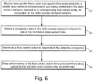
- FIG. 6 is a flow chart illustrating non-limiting example procedures for congestion detection and notification in a radio access transport network.
- Multiple data packet flows are each associated with a mobile radio terminal communication, and each flow is controlled in the radio access transport network by a corresponding flow control entity. They are monitored for congestion in the transport network (step S1). If a congestion area in the transport network is detected for one of the monitored data packet flows (step S2), then a flow control action is determined in response to the detected congestion (step S3).
- the detected congestion area may be for example a shared congested communications link in the radio access transport network, a shared congested radio network controller, or a shared congested radio base station. Performance of the flow control action is delayed for a predetermined delay period before the flow control action may be performed (step S4). Delaying flow control action after congestion is detected allows other affected flows to detect or be notified of the congestion, thereby making congestion detection more fair.
- Figure 7 shows a non-limiting example implementation with both downlink (DL) and uplink (UL) flow congestion detection, notification, and control.
- Downlink flow congestion detection, notification, and control are shown in the upper portion of the figure and uplink flow flow congestion detection, notification, and control in the lower portion.
- a DRT timer 38 is shown in the RNC and periodically generates time stamp values, e.g., every 1 ms, which are inserted in the downlink data frame Iub/Iur DF sent to the Node B.
- the Node B also shows a packet queue (PQ) coupled to the Uu scheduler 34 with a line from the PQ 37 to the congestion detection functionality 30 indicating that the queue length is monitored for congestion detection purposes.
- the congestion controllers 38 in this example include prohibit timers 39 as described above.
- Figure 8A and 8B show example HS-DSCH data frame structures. Both include frame sequence number (FSN) and DRT fields.
- Figure 9 shows an example E-DCH UL data frame structure which includes an FSN field. There is no a dedicated field for DRT in EUL, but from FSN and CFN field and the sub frame number the DRT value may be calculated.
- FIG 10 shows an example transport network congestion information (TCI) control frame that carries congestion status information about one or more data packet flows affected by a particular congestion bottleneck in the transport network.
- the TCI may contain a congestion status field, which can for example indicate for each flow no congestion, congestion due to delay build-up, congestion due to frame loss, etc.
- the congestion controller in the Node B for the downlink and in the RNC for the uplink may be used to generate and send TCI control frames to bit rate calculation functionalities associated with affected flows as shown in Figure 7 .
- a congestion-relevant decision might be the SRNC previously identified for this flow based on a DRT value. Based on such a table, the most probable SRNC is identified. This additional information permits more robust decision-making. For example, if the last four decisions identified RNC-X as a congestion area for certain flows, and there is some uncertainty for a current decision between RNC-X and RNC-Y based on the current DRT value, then this history can be used to select RNC-X for the current congestion decision.
- the congestion area may be the same SRNC or the same Node B, but it may also be the same transport network link or parallel transport network links that have the same SRNC and the same Node B. For example, assume there are two physical connections between an RNC and a Node B. In this situation, in addition to the DRT-based bottleneck detection, it is useful to determine one-way delay and/or packet loss pattern for flows. Based on DRT values, it is determined that two flows have the same RNC and Node B and share the same congestion area. But if there is a significant difference in the packet loss pattern or one-way delay for these flows, then it is determined that they are affected by different congestion areas.
- the decision may be made that the two flows are experiencing congestion at different transport network bottlenecks.
- Different transport network quality of service (QoS) levels may also be identified in a similar way as with parallel transport network links to identify multiple transport network bottlenecks.
- Congestion detection for a particular flow may also be facilitated by grouping of flows having the same RNC and similar queuing delay estimated based on previously-detected DRT values of the flows in the group or a history of DRT values for the group. For example, if the queuing delays within a group are significantly different while their DRT values are similar, then it can be determined that there are parallel transport network links for flows within that group.
- a group of flows may also be generated based on observing packet loss patterns for different flows. If a group of flows have similar packet loss patterns, then those flows are probably affected by the same bottleneck. Notification of the congestion affecting a group of flows may be limited to just those flows in the group.
- delaying performance of the flow control action for the predetermined delay period occurs whenever congestion is detected in the radio access transport network. In another example embodiment, delaying performance of the flow control action for the predetermined delay period occurs for some but not all of the times when congestion is detected in the radio access transport network.
- delaying performance of the flow control action for the predetermined delay period occurs only if the detected congestion is a predetermined type of congestion.
- different delay values may be used for different congestion types.
- congestion types might include hard congestion and soft congestion as described earlier.
- the predetermined delay period may include a first delay associated with detecting a soft type of congestion and a second, shorter delay associated with detecting a hard type of congestion. Assume for a non-limiting example that a soft congestion delay limit is 40 ms and a hard congestion delay limit is 60 ms. Congestion action might be delayed for 150 ms for the soft congestion but only for 100 ms for the hard congestion.
- delaying performance of the flow control action for the predetermined delay period occurs only if the monitored data packet flow is associated with a particular service class or user class (e.g., gold, silver, or bronze user classes).
- a particular service class or user class e.g., gold, silver, or bronze user classes.
- a maximum delay value actually waited in a recent prior time interval may be determined. If the maximum delay value exceeds the predetermined delay period, then the flow control action initiated for a current congestion detection is performed or a flow control action message is sent without waiting predetermined delay period.
- a maximum delay value for a particular data packet flow is already determined during a most recent 100 ms interval. If soft congestion is now detected, but the previously determined delay value is significantly larger than the 40 ms delay limit normally used for soft congestion, then no further delay of the flow control action is imposed.
- the fair transport network congestion detection and notification technology described allows fairness in use of limited transport network communication resources by multiple data packet flows that are subject to a congestion bottleneck associated with those resources. Because all or at least most of the affected flows become or are made aware of the congestion situation, their bit rates, for example, can be reduced fairly. This technology is also useful for short buffer cases where the buffer is not large enough for delay based congestion detection. For example, if the delay limit for soft congestion is 40 ms and the buffer is shorter than 40 ms, then soft congestion is not detected. In these short buffer cases, congestion detection may be based on packet loss.
- Another advantage of this fair transport network congestion detection and notification technology is that it maintains separation between the Iur and Iub interfaces. If only the Iur interface is congested, then the flows using only the Iub interface will not detect congestion. As a result, the Iur and Iub interfaces are handled correctly in the sense that flows using a common Iub transport network link are not informed about congestion on an Iur transport network link.
- the fair transport network congestion detection and notification technology also provides a robust way to identify the RNC of a data packet flow, is relatively easy to implement, can be used for both downlink and uplink HSPA, and does not pose an interoperability problem.
Landscapes
- Engineering & Computer Science (AREA)
- Computer Networks & Wireless Communication (AREA)
- Signal Processing (AREA)
- Databases & Information Systems (AREA)
- Data Exchanges In Wide-Area Networks (AREA)
- Mobile Radio Communication Systems (AREA)
Claims (26)
- Procédé de détection et de notification d'encombrement dans un réseau de transport d'accès radio incluant un ou plusieurs contrôleurs de réseau radio couplés à une ou plusieurs stations de base radio, comprenant :la surveillance (S1) de flux de paquets de données, chaque flux de paquets de données associé à une communication de terminal radio mobile et étant commandé dans le réseau de transport d'accès radio par une entité de commande de flux correspondante, à la recherche d'un encombrement dans le réseau de transport d'accès radio ;la détection (S2) d'un encombrement dans le réseau de transport d'accès radio pour l'un des flux de paquets de données surveillés ;la détermination (S3) d'une action de commande de flux en réponse à l'encombrement détecté ; etle retardement (S4) de la mise en oeuvre de l'action de commande de flux pendant une période de retard prédéterminée.
- Procédé selon la revendication 1, dans lequel la période de retard prédéterminée peut être variée sur la base de différentes valeurs de période de retard prédéterminées.
- Procédé selon la revendication 1 ou 2, dans lequel l'encombrement détecté dans le réseau de transport d'accès radio est une liaison de communication encombrée partagée dans le réseau de transport d'accès radio, un contrôleur de réseau radio encombré partagé, ou une station de base radio encombrée partagée.
- Procédé selon l'une quelconque des revendications 1 à 3, dans lequel le retardement de mise en oeuvre de l'action de commande de flux pendant la période de retard prédéterminée se produit chaque fois qu'un encombrement est détecté dans le réseau de transport d'accès radio.
- Procédé selon l'une quelconque des revendications 1 à 3, dans lequel le retardement de mise en oeuvre de l'action de commande de flux pendant la période de retard prédéterminée se produit pour certaines fois, mais pas toutes, où un encombrement est détecté dans le réseau de transport d'accès radio
- Procédé selon la revendication 5, dans lequel le retardement de mise en oeuvre de l'action de commande de flux pendant la période de retard prédéterminée se produit uniquement si l'encombrement détecté est l'un parmi un ensemble de types prédéterminés d'encombrement.
- Procédé selon la revendication 5, dans lequel le retardement de mise en oeuvre de l'action de commande de flux pendant la période de retard prédéterminée se produit si le flux de paquets de données surveillé est associé à une classe de service particulière.
- Procédé selon l'une quelconque des revendications 1 à 7, dans lequel la période de retard prédéterminée inclut un premier retard associé à la détection d'un type d'encombrement logiciel et un deuxième retard plus court associé à la détection d'un type d'encombrement matériel.
- Procédé selon l'une quelconque des revendications 1 à 8, dans lequel l'action de commande de flux inclut la réduction d'un débit binaire pour l'un des flux de paquets de données surveillés, détecté comme étant encombré.
- Procédé selon l'une quelconque des revendications 1 à 9, le procédé comprenant en outre :la détermination d'une valeur de retard maximale réellement attendue pour ce flux de paquets de données dans un intervalle de temps antérieur récent ; etsi la valeur de retard maximale dépasse la période de retard prédéterminée, l'envoi alors du message d'action de commande de flux généré pour ce flux de paquets de données sans attendre la période de retard prédéterminée.
- Procédé selon l'une quelconque des revendications 1 à 10, implémenté dans une direction de liaison descendante depuis un contrôleur de réseau radio jusqu'à une station de base radio ou dans une direction de liaison montante depuis une station de base radio jusqu'à un contrôleur de réseau radio.
- Procédé selon l'une quelconque des revendications 1 à 11, le procédé comprenant en outre :la génération d'un message d'action de commande de flux généré en réponse à l'encombrement détecté ;le retardement d'envoi du message d'action de commande de flux généré pendant la période de retard prédéterminée ; etaprès avoir attendu pendant la période de retard prédéterminée, l'envoi du message d'action de commande de flux généré de sorte qu'une ou plusieurs des entités de commande de flux peuvent entreprendre une action de commande de flux sur la base de l'encombrement détecté.
- Procédé selon l'une quelconque des revendications 1 à 11, le procédé comprenant en outre :la génération d'un message d'action de commande de flux généré en réponse à l'encombrement détecté ;l'envoi du message d'action de commande de flux généré ; etl'attente pendant la période de retard prédéterminée après que le message d'action de commande de flux généré est reçu, puis la mise en oeuvre d'une action de commande de flux en réponse au message d'action de commande de flux.
- Noeud de réseau de transport d'accès radio (14, 16) pour une utilisation dans un réseau de transport d'accès radio incluant un ou plusieurs contrôleurs de réseau radio (16) couplés à une ou plusieurs stations de base radio (14), comprenant des circuits électroniques configurés pour :surveiller des flux de paquets de données, chaque flux de paquets de données associé à une communication de terminal radio mobile et étant commandé dans le réseau de transport d'accès radio par une entité de commande de flux correspondante, à la recherche d'un encombrement dans le réseau de transport d'accès radio ;détecter un encombrement dans le réseau de transport d'accès radio pour l'un des flux de paquets de données surveillés ;déterminer une action de commande de flux en réponse à l'encombrement détecté ; etretarder la mise en oeuvre de l'action de commande de flux pendant une période de retard prédéterminée avant que l'action de commande de flux puisse être mise en oeuvre.
- Noeud de réseau de transport d'accès radio selon la revendication 14, dans lequel la période de retard prédéterminée peut être variée sur la base de différentes valeurs de période de retard prédéterminées.
- Noeud de réseau de transport d'accès radio selon la revendication 14 ou 15, dans lequel l'encombrement détecté dans le réseau de transport d'accès radio est une liaison de communication encombrée partagée dans le réseau de transport d'accès radio, un contrôleur de réseau radio encombré partagé, ou une station de base radio encombrée partagée.
- Noeud de réseau de transport d'accès radio selon l'une quelconque des revendications 14 à 16, dans lequel le retard de mise en oeuvre de l'action de commande de flux pendant la période de retard prédéterminée se produit chaque fois qu'un encombrement est détecté dans le réseau de transport d'accès radio.
- Noeud de réseau de transport d'accès radio selon l'une quelconque des revendications 14 à 16, dans lequel le retard de mise en oeuvre de l'action de commande de flux pendant la période de retard prédéterminée se produit pour certaines fois, mais pas toutes, où un encombrement est détecté dans le réseau de transport d'accès radio
- Noeud de réseau de transport d'accès radio selon la revendication 18, dans lequel le retard de mise en oeuvre de l'action de commande de flux pendant la période de retard prédéterminée se produit uniquement si l'encombrement détecté est l'un parmi un ensemble de types prédéterminés d'encombrement.
- Noeud de réseau de transport d'accès radio selon la revendication 18, dans lequel le retard de mise en oeuvre de l'action de commande de flux pendant la période de retard prédéterminée se produit si le flux de paquets de données surveillé est associé à une classe de service particulière.
- Noeud de réseau de transport d'accès radio selon l'une quelconque des revendications 14 à 20, dans lequel la période de retard prédéterminée inclut un premier retard associé à la détection d'un type d'encombrement logiciel et un deuxième retard plus court associé à la détection d'un type d'encombrement matériel
- Noeud de réseau de transport d'accès radio selon l'une quelconque des revendications 14 à 21, dans lequel l'action de commande de flux inclut la réduction d'un débit binaire pour l'un des flux de paquets de données surveillés, détecté comme étant encombré.
- Noeud de réseau de transport d'accès radio selon l'une quelconque des revendications 14 à 22, dans lequel les circuits électroniques sont configurés en outre pour :déterminer une valeur de retard maximale réellement attendue pour ce flux de paquets de données dans un intervalle de temps antérieur récent ; etenvoyer un message d'action de commande de flux pour ce flux de paquets de données sans attendre la période de retard prédéterminée si la valeur de retard maximale dépasse la période de retard prédéterminée.
- Noeud de réseau de transport d'accès radio selon l'une quelconque des revendications 14 à 23, dans lequel le noeud de réseau de transport d'accès radio est une station de base radio.
- Noeud de réseau de transport d'accès radio selon l'une quelconque des revendications 14 à 23, dans lequel le noeud de réseau de transport d'accès radio est un contrôleur de réseau radio.
- Système de communications radio incluant un réseau de transport d'accès radio incluant un ou plusieurs des noeuds de réseau de transport d'accès radio selon la revendication 14 et un ou plusieurs terminaux radio communiquant via le réseau de transport d'accès radio.
Applications Claiming Priority (2)
| Application Number | Priority Date | Filing Date | Title |
|---|---|---|---|
| US12/730,752 US8619573B2 (en) | 2010-03-24 | 2010-03-24 | Delayed flow control action in transport network layer WCDMA communications |
| PCT/SE2011/050228 WO2011119087A1 (fr) | 2010-03-24 | 2011-02-28 | Action temporisée de contrôle de flux dans des communications wcdma à couche de réseau de transport |
Publications (3)
| Publication Number | Publication Date |
|---|---|
| EP2550823A1 EP2550823A1 (fr) | 2013-01-30 |
| EP2550823A4 EP2550823A4 (fr) | 2016-08-31 |
| EP2550823B1 true EP2550823B1 (fr) | 2019-01-09 |
Family
ID=44656389
Family Applications (1)
| Application Number | Title | Priority Date | Filing Date |
|---|---|---|---|
| EP11759789.8A Active EP2550823B1 (fr) | 2010-03-24 | 2011-02-28 | Action temporisée de contrôle de flux dans des communications wcdma à couche de réseau de transport |
Country Status (3)
| Country | Link |
|---|---|
| US (1) | US8619573B2 (fr) |
| EP (1) | EP2550823B1 (fr) |
| WO (1) | WO2011119087A1 (fr) |
Families Citing this family (14)
| Publication number | Priority date | Publication date | Assignee | Title |
|---|---|---|---|---|
| US8891356B2 (en) | 2010-06-28 | 2014-11-18 | Qualcomm Incorporated | System and method for multi-point HSDPA communication utilizing a multi-link RLC sublayer |
| US20120163205A1 (en) * | 2010-06-28 | 2012-06-28 | Qualcomm Incorporated | System and method for flow control in a multi-point hsdpa communication network |
| US8989140B2 (en) | 2010-06-28 | 2015-03-24 | Qualcomm Incorporated | System and method for mobility in a multi-point HSDPA communication network |
| US8565091B2 (en) * | 2010-10-28 | 2013-10-22 | Telefonaktiebolaget L M Ericsson (Publ) | Dynamic control of air interface throughput |
| US8989004B2 (en) | 2010-11-08 | 2015-03-24 | Qualcomm Incorporated | System and method for multi-point HSDPA communication utilizing a multi-link PDCP sublayer |
| US8737211B2 (en) | 2011-08-03 | 2014-05-27 | Qualcomm Incorporated | Methods and apparatuses for network configuration of user equipment communication modes in multiflow systems |
| US9125098B2 (en) | 2011-08-03 | 2015-09-01 | Qualcomm Incorporated | Method and apparatus for flow congestion control in multiflow networks |
| US8780722B2 (en) * | 2012-02-03 | 2014-07-15 | Apple Inc. | Scheduling packet transmission on a client device using packet classifications including high priority network control packets |
| US10341245B2 (en) * | 2014-03-24 | 2019-07-02 | Vmware, Inc. | Bursty data transmission in a congestion controlled network |
| CN106470126A (zh) * | 2015-08-14 | 2017-03-01 | 中兴通讯股份有限公司 | 端口队列堵塞的监控方法及系统 |
| WO2017063717A1 (fr) * | 2015-10-16 | 2017-04-20 | Telefonaktiebolaget Lm Ericsson (Publ) | Procédé et appareil de communication en réseau par une interface |
| US10404609B2 (en) * | 2017-12-14 | 2019-09-03 | Litepoint Corporation | Method for delaying signal transmissions from a device under test (DUT) by transmitting congestive communication channel signals |
| TWI769298B (zh) | 2018-08-31 | 2022-07-01 | 佳能企業股份有限公司 | 光學鏡頭 |
| CN114938350B (zh) * | 2022-06-15 | 2023-08-22 | 长沙理工大学 | 数据中心无损网络中基于拥塞反馈的数据流传输控制方法 |
Family Cites Families (23)
| Publication number | Priority date | Publication date | Assignee | Title |
|---|---|---|---|---|
| EP0955749A1 (fr) | 1998-05-08 | 1999-11-10 | Nortel Networks Corporation | Commande d'encombrement par un récepteur et avis d'encombrement du routeur |
| US6728211B1 (en) * | 2000-03-07 | 2004-04-27 | Cisco Technology, Inc. | Method and apparatus for delaying packets being sent from a component of a packet switching system |
| US6826147B1 (en) | 2000-07-25 | 2004-11-30 | Nortel Networks Limited | Method and apparatus for aggregate flow control in a differentiated services network |
| US6889050B1 (en) * | 2000-11-22 | 2005-05-03 | Telefonaktiebolaget Lm Ericsson (Publ) | Variable transmission rate services in a radio access network |
| US7961616B2 (en) * | 2001-06-07 | 2011-06-14 | Qualcomm Incorporated | Method and apparatus for congestion control in a wireless communication system |
| US7295516B1 (en) | 2001-11-13 | 2007-11-13 | Verizon Services Corp. | Early traffic regulation techniques to protect against network flooding |
| US9414255B2 (en) | 2002-09-13 | 2016-08-09 | Alcatel Lucent | Packet flow control in a wireless communications network based on an indication contained in a packet |
| US20070286132A1 (en) * | 2004-03-12 | 2007-12-13 | Vikberg Jari | Unlicensed-Licensed Interworking Enhancement Through the Implementation of an Specific Link Control Protocol Layer with Packet Prioritization |
| US7593329B2 (en) | 2004-10-29 | 2009-09-22 | Broadcom Corporation | Service aware flow control |
| US7626926B2 (en) * | 2004-12-09 | 2009-12-01 | Airvana, Inc. | Traffic management in a wireless data network |
| US7724656B2 (en) * | 2005-01-14 | 2010-05-25 | Telefonaktiebolaget Lm Ericsson (Publ) | Uplink congestion detection and control between nodes in a radio access network |
| FR2895616A1 (fr) * | 2005-12-27 | 2007-06-29 | France Telecom | Mecanisme auto-adaptatif de gestion de flux dans un reseau partage a acces multiple |
| US9306853B2 (en) * | 2006-07-06 | 2016-04-05 | Alcatel Lucent | Maintaining quality of service for multi-media packet data services in a transport network |
| US8000242B2 (en) * | 2006-07-06 | 2011-08-16 | Alcatel Lucent | Reducing packet loss for a packet data service during congestion in a transport network |
| US8125967B1 (en) * | 2006-11-10 | 2012-02-28 | Sprint Spectrum L.P. | Prioritized EV-DO paging based on type of packet flow |
| EP1926257A1 (fr) | 2006-11-27 | 2008-05-28 | Nokia Siemens Networks Gmbh & Co. Kg | Contrôle de la congestion dans un réseau d'accès radio |
| WO2008066427A1 (fr) * | 2006-11-28 | 2008-06-05 | Telefonaktiebolaget Lm Ericsson (Publ) | Procédé pour une détection et une régulation améliorées d'encombrement et commande dans un système de télécommunications sans fil |
| CN101543112A (zh) * | 2006-11-28 | 2009-09-23 | 艾利森电话股份有限公司 | 蜂窝电话系统中的增强流控制 |
| EP2204017B1 (fr) | 2007-11-01 | 2012-05-16 | Telefonaktiebolaget L M Ericsson (publ) | Régulation efficace d'un flux dans un rnc |
| US8917598B2 (en) * | 2007-12-21 | 2014-12-23 | Qualcomm Incorporated | Downlink flow control |
| US8553554B2 (en) * | 2008-05-16 | 2013-10-08 | Alcatel Lucent | Method and apparatus for providing congestion control in radio access networks |
| WO2009155031A2 (fr) | 2008-05-28 | 2009-12-23 | Camiant, Inc. | Procédé et système de gestion pour une utilisation équitable |
| ES2334963B1 (es) * | 2008-08-14 | 2011-02-09 | Vodafone España, S.A.U. | Metodo para reducir la congestion en la interfaz iub en redes utran segun el establecimiento de prioridad del usuario. |
-
2010
- 2010-03-24 US US12/730,752 patent/US8619573B2/en active Active
-
2011
- 2011-02-28 WO PCT/SE2011/050228 patent/WO2011119087A1/fr active Application Filing
- 2011-02-28 EP EP11759789.8A patent/EP2550823B1/fr active Active
Non-Patent Citations (1)
| Title |
|---|
| None * |
Also Published As
| Publication number | Publication date |
|---|---|
| EP2550823A1 (fr) | 2013-01-30 |
| WO2011119087A1 (fr) | 2011-09-29 |
| US20110235519A1 (en) | 2011-09-29 |
| US8619573B2 (en) | 2013-12-31 |
| EP2550823A4 (fr) | 2016-08-31 |
Similar Documents
| Publication | Publication Date | Title |
|---|---|---|
| US8493860B2 (en) | Fair congestion detection for transport network layer WCDMA communications | |
| EP2550823B1 (fr) | Action temporisée de contrôle de flux dans des communications wcdma à couche de réseau de transport | |
| US9232430B2 (en) | Congestion control within a radio access network | |
| US8107440B2 (en) | Transport network congestion control for enhanced uplink communications | |
| EP1836866B1 (fr) | Detection et prevention des encombrements des liaisons remontante entre noeuds dans un reseau d'acces radio | |
| US9100871B2 (en) | Hybrid congestion control | |
| RU2515997C2 (ru) | Активное управление очередью для восходящей линии связи в сети беспроводной связи | |
| US8369221B2 (en) | Efficient flow control in a radio network controller (RNC) | |
| US20060203760A1 (en) | Base station device and transmission method | |
| KR101850664B1 (ko) | 무선 통신 시스템, 이동국, 기지국 및 무선 통신 방법 | |
| US9497647B2 (en) | Methods and devices for reporting in a cellular radio network | |
| US20150180786A1 (en) | Method for setting parameter in data transmission service, terminal, and base station | |
| EP2087663A1 (fr) | Commande de flux améliorée dans un système de téléphonie cellulaire | |
| CN101631008B (zh) | 一种通知负荷状态的方法及装置 | |
| JP6481711B2 (ja) | 無線通信システム、移動局、基地局及び無線通信方法 | |
| KR20060082733A (ko) | 이동통신 시스템에서 이벤트 트리거드로 버퍼 상태 보고를효율적으로 하는 방법 및 장치 | |
| KR20070053370A (ko) | 무선 액세스 네트워크 내의 정체 제어 |
Legal Events
| Date | Code | Title | Description |
|---|---|---|---|
| PUAI | Public reference made under article 153(3) epc to a published international application that has entered the european phase |
Free format text: ORIGINAL CODE: 0009012 |
|
| 17P | Request for examination filed |
Effective date: 20120913 |
|
| AK | Designated contracting states |
Kind code of ref document: A1 Designated state(s): AL AT BE BG CH CY CZ DE DK EE ES FI FR GB GR HR HU IE IS IT LI LT LU LV MC MK MT NL NO PL PT RO RS SE SI SK SM TR |
|
| DAX | Request for extension of the european patent (deleted) | ||
| RA4 | Supplementary search report drawn up and despatched (corrected) |
Effective date: 20160803 |
|
| RIC1 | Information provided on ipc code assigned before grant |
Ipc: H04W 72/00 20090101ALI20160728BHEP Ipc: H04W 28/02 20090101AFI20160728BHEP |
|
| 17Q | First examination report despatched |
Effective date: 20160819 |
|
| STAA | Information on the status of an ep patent application or granted ep patent |
Free format text: STATUS: EXAMINATION IS IN PROGRESS |
|
| GRAP | Despatch of communication of intention to grant a patent |
Free format text: ORIGINAL CODE: EPIDOSNIGR1 |
|
| STAA | Information on the status of an ep patent application or granted ep patent |
Free format text: STATUS: GRANT OF PATENT IS INTENDED |
|
| GRAS | Grant fee paid |
Free format text: ORIGINAL CODE: EPIDOSNIGR3 |
|
| INTG | Intention to grant announced |
Effective date: 20181109 |
|
| GRAA | (expected) grant |
Free format text: ORIGINAL CODE: 0009210 |
|
| STAA | Information on the status of an ep patent application or granted ep patent |
Free format text: STATUS: THE PATENT HAS BEEN GRANTED |
|
| AK | Designated contracting states |
Kind code of ref document: B1 Designated state(s): AL AT BE BG CH CY CZ DE DK EE ES FI FR GB GR HR HU IE IS IT LI LT LU LV MC MK MT NL NO PL PT RO RS SE SI SK SM TR |
|
| REG | Reference to a national code |
Ref country code: GB Ref legal event code: FG4D |
|
| REG | Reference to a national code |
Ref country code: CH Ref legal event code: EP Ref country code: AT Ref legal event code: REF Ref document number: 1088854 Country of ref document: AT Kind code of ref document: T Effective date: 20190115 |
|
| REG | Reference to a national code |
Ref country code: DE Ref legal event code: R096 Ref document number: 602011055573 Country of ref document: DE |
|
| REG | Reference to a national code |
Ref country code: IE Ref legal event code: FG4D |
|
| REG | Reference to a national code |
Ref country code: NL Ref legal event code: FP |
|
| REG | Reference to a national code |
Ref country code: LT Ref legal event code: MG4D |
|
| REG | Reference to a national code |
Ref country code: AT Ref legal event code: MK05 Ref document number: 1088854 Country of ref document: AT Kind code of ref document: T Effective date: 20190109 |
|
| PG25 | Lapsed in a contracting state [announced via postgrant information from national office to epo] |
Ref country code: ES Free format text: LAPSE BECAUSE OF FAILURE TO SUBMIT A TRANSLATION OF THE DESCRIPTION OR TO PAY THE FEE WITHIN THE PRESCRIBED TIME-LIMIT Effective date: 20190109 Ref country code: PL Free format text: LAPSE BECAUSE OF FAILURE TO SUBMIT A TRANSLATION OF THE DESCRIPTION OR TO PAY THE FEE WITHIN THE PRESCRIBED TIME-LIMIT Effective date: 20190109 Ref country code: FI Free format text: LAPSE BECAUSE OF FAILURE TO SUBMIT A TRANSLATION OF THE DESCRIPTION OR TO PAY THE FEE WITHIN THE PRESCRIBED TIME-LIMIT Effective date: 20190109 Ref country code: LT Free format text: LAPSE BECAUSE OF FAILURE TO SUBMIT A TRANSLATION OF THE DESCRIPTION OR TO PAY THE FEE WITHIN THE PRESCRIBED TIME-LIMIT Effective date: 20190109 Ref country code: PT Free format text: LAPSE BECAUSE OF FAILURE TO SUBMIT A TRANSLATION OF THE DESCRIPTION OR TO PAY THE FEE WITHIN THE PRESCRIBED TIME-LIMIT Effective date: 20190509 Ref country code: NO Free format text: LAPSE BECAUSE OF FAILURE TO SUBMIT A TRANSLATION OF THE DESCRIPTION OR TO PAY THE FEE WITHIN THE PRESCRIBED TIME-LIMIT Effective date: 20190409 Ref country code: SE Free format text: LAPSE BECAUSE OF FAILURE TO SUBMIT A TRANSLATION OF THE DESCRIPTION OR TO PAY THE FEE WITHIN THE PRESCRIBED TIME-LIMIT Effective date: 20190109 |
|
| PG25 | Lapsed in a contracting state [announced via postgrant information from national office to epo] |
Ref country code: RS Free format text: LAPSE BECAUSE OF FAILURE TO SUBMIT A TRANSLATION OF THE DESCRIPTION OR TO PAY THE FEE WITHIN THE PRESCRIBED TIME-LIMIT Effective date: 20190109 Ref country code: BG Free format text: LAPSE BECAUSE OF FAILURE TO SUBMIT A TRANSLATION OF THE DESCRIPTION OR TO PAY THE FEE WITHIN THE PRESCRIBED TIME-LIMIT Effective date: 20190409 Ref country code: LV Free format text: LAPSE BECAUSE OF FAILURE TO SUBMIT A TRANSLATION OF THE DESCRIPTION OR TO PAY THE FEE WITHIN THE PRESCRIBED TIME-LIMIT Effective date: 20190109 Ref country code: IS Free format text: LAPSE BECAUSE OF FAILURE TO SUBMIT A TRANSLATION OF THE DESCRIPTION OR TO PAY THE FEE WITHIN THE PRESCRIBED TIME-LIMIT Effective date: 20190509 Ref country code: HR Free format text: LAPSE BECAUSE OF FAILURE TO SUBMIT A TRANSLATION OF THE DESCRIPTION OR TO PAY THE FEE WITHIN THE PRESCRIBED TIME-LIMIT Effective date: 20190109 Ref country code: GR Free format text: LAPSE BECAUSE OF FAILURE TO SUBMIT A TRANSLATION OF THE DESCRIPTION OR TO PAY THE FEE WITHIN THE PRESCRIBED TIME-LIMIT Effective date: 20190410 |
|
| REG | Reference to a national code |
Ref country code: CH Ref legal event code: PL |
|
| REG | Reference to a national code |
Ref country code: DE Ref legal event code: R097 Ref document number: 602011055573 Country of ref document: DE |
|
| PG25 | Lapsed in a contracting state [announced via postgrant information from national office to epo] |
Ref country code: SK Free format text: LAPSE BECAUSE OF FAILURE TO SUBMIT A TRANSLATION OF THE DESCRIPTION OR TO PAY THE FEE WITHIN THE PRESCRIBED TIME-LIMIT Effective date: 20190109 Ref country code: EE Free format text: LAPSE BECAUSE OF FAILURE TO SUBMIT A TRANSLATION OF THE DESCRIPTION OR TO PAY THE FEE WITHIN THE PRESCRIBED TIME-LIMIT Effective date: 20190109 Ref country code: CZ Free format text: LAPSE BECAUSE OF FAILURE TO SUBMIT A TRANSLATION OF THE DESCRIPTION OR TO PAY THE FEE WITHIN THE PRESCRIBED TIME-LIMIT Effective date: 20190109 Ref country code: RO Free format text: LAPSE BECAUSE OF FAILURE TO SUBMIT A TRANSLATION OF THE DESCRIPTION OR TO PAY THE FEE WITHIN THE PRESCRIBED TIME-LIMIT Effective date: 20190109 Ref country code: MC Free format text: LAPSE BECAUSE OF FAILURE TO SUBMIT A TRANSLATION OF THE DESCRIPTION OR TO PAY THE FEE WITHIN THE PRESCRIBED TIME-LIMIT Effective date: 20190109 Ref country code: AL Free format text: LAPSE BECAUSE OF FAILURE TO SUBMIT A TRANSLATION OF THE DESCRIPTION OR TO PAY THE FEE WITHIN THE PRESCRIBED TIME-LIMIT Effective date: 20190109 Ref country code: LU Free format text: LAPSE BECAUSE OF NON-PAYMENT OF DUE FEES Effective date: 20190228 Ref country code: AT Free format text: LAPSE BECAUSE OF FAILURE TO SUBMIT A TRANSLATION OF THE DESCRIPTION OR TO PAY THE FEE WITHIN THE PRESCRIBED TIME-LIMIT Effective date: 20190109 Ref country code: DK Free format text: LAPSE BECAUSE OF FAILURE TO SUBMIT A TRANSLATION OF THE DESCRIPTION OR TO PAY THE FEE WITHIN THE PRESCRIBED TIME-LIMIT Effective date: 20190109 Ref country code: IT Free format text: LAPSE BECAUSE OF FAILURE TO SUBMIT A TRANSLATION OF THE DESCRIPTION OR TO PAY THE FEE WITHIN THE PRESCRIBED TIME-LIMIT Effective date: 20190109 |
|
| PLBE | No opposition filed within time limit |
Free format text: ORIGINAL CODE: 0009261 |
|
| STAA | Information on the status of an ep patent application or granted ep patent |
Free format text: STATUS: NO OPPOSITION FILED WITHIN TIME LIMIT |
|
| REG | Reference to a national code |
Ref country code: BE Ref legal event code: MM Effective date: 20190228 |
|
| REG | Reference to a national code |
Ref country code: IE Ref legal event code: MM4A |
|
| PG25 | Lapsed in a contracting state [announced via postgrant information from national office to epo] |
Ref country code: SM Free format text: LAPSE BECAUSE OF FAILURE TO SUBMIT A TRANSLATION OF THE DESCRIPTION OR TO PAY THE FEE WITHIN THE PRESCRIBED TIME-LIMIT Effective date: 20190109 |
|
| 26N | No opposition filed |
Effective date: 20191010 |
|
| PG25 | Lapsed in a contracting state [announced via postgrant information from national office to epo] |
Ref country code: CH Free format text: LAPSE BECAUSE OF NON-PAYMENT OF DUE FEES Effective date: 20190228 Ref country code: LI Free format text: LAPSE BECAUSE OF NON-PAYMENT OF DUE FEES Effective date: 20190228 |
|
| PG25 | Lapsed in a contracting state [announced via postgrant information from national office to epo] |
Ref country code: IE Free format text: LAPSE BECAUSE OF NON-PAYMENT OF DUE FEES Effective date: 20190228 |
|
| PG25 | Lapsed in a contracting state [announced via postgrant information from national office to epo] |
Ref country code: BE Free format text: LAPSE BECAUSE OF NON-PAYMENT OF DUE FEES Effective date: 20190228 Ref country code: FR Free format text: LAPSE BECAUSE OF NON-PAYMENT OF DUE FEES Effective date: 20190309 Ref country code: SI Free format text: LAPSE BECAUSE OF FAILURE TO SUBMIT A TRANSLATION OF THE DESCRIPTION OR TO PAY THE FEE WITHIN THE PRESCRIBED TIME-LIMIT Effective date: 20190109 |
|
| PG25 | Lapsed in a contracting state [announced via postgrant information from national office to epo] |
Ref country code: TR Free format text: LAPSE BECAUSE OF FAILURE TO SUBMIT A TRANSLATION OF THE DESCRIPTION OR TO PAY THE FEE WITHIN THE PRESCRIBED TIME-LIMIT Effective date: 20190109 |
|
| PG25 | Lapsed in a contracting state [announced via postgrant information from national office to epo] |
Ref country code: MT Free format text: LAPSE BECAUSE OF NON-PAYMENT OF DUE FEES Effective date: 20190228 |
|
| PG25 | Lapsed in a contracting state [announced via postgrant information from national office to epo] |
Ref country code: CY Free format text: LAPSE BECAUSE OF FAILURE TO SUBMIT A TRANSLATION OF THE DESCRIPTION OR TO PAY THE FEE WITHIN THE PRESCRIBED TIME-LIMIT Effective date: 20190109 |
|
| PG25 | Lapsed in a contracting state [announced via postgrant information from national office to epo] |
Ref country code: HU Free format text: LAPSE BECAUSE OF FAILURE TO SUBMIT A TRANSLATION OF THE DESCRIPTION OR TO PAY THE FEE WITHIN THE PRESCRIBED TIME-LIMIT; INVALID AB INITIO Effective date: 20110228 |
|
| PG25 | Lapsed in a contracting state [announced via postgrant information from national office to epo] |
Ref country code: MK Free format text: LAPSE BECAUSE OF FAILURE TO SUBMIT A TRANSLATION OF THE DESCRIPTION OR TO PAY THE FEE WITHIN THE PRESCRIBED TIME-LIMIT Effective date: 20190109 |
|
| PGFP | Annual fee paid to national office [announced via postgrant information from national office to epo] |
Ref country code: NL Payment date: 20240226 Year of fee payment: 14 |
|
| PGFP | Annual fee paid to national office [announced via postgrant information from national office to epo] |
Ref country code: DE Payment date: 20240228 Year of fee payment: 14 Ref country code: GB Payment date: 20240227 Year of fee payment: 14 |