EP2550669B1 - Sealed circuit breaker - Google Patents
Sealed circuit breaker Download PDFInfo
- Publication number
- EP2550669B1 EP2550669B1 EP10727538.0A EP10727538A EP2550669B1 EP 2550669 B1 EP2550669 B1 EP 2550669B1 EP 10727538 A EP10727538 A EP 10727538A EP 2550669 B1 EP2550669 B1 EP 2550669B1
- Authority
- EP
- European Patent Office
- Prior art keywords
- circuit breaker
- bottom housing
- electrical
- end wall
- aperture
- Prior art date
- Legal status (The legal status is an assumption and is not a legal conclusion. Google has not performed a legal analysis and makes no representation as to the accuracy of the status listed.)
- Active
Links
Images







Classifications
-
- H—ELECTRICITY
- H01—ELECTRIC ELEMENTS
- H01H—ELECTRIC SWITCHES; RELAYS; SELECTORS; EMERGENCY PROTECTIVE DEVICES
- H01H9/00—Details of switching devices, not covered by groups H01H1/00 - H01H7/00
- H01H9/02—Bases, casings, or covers
- H01H9/04—Dustproof, splashproof, drip-proof, waterproof, or flameproof casings
- H01H9/042—Explosion-proof cases
-
- H—ELECTRICITY
- H01—ELECTRIC ELEMENTS
- H01H—ELECTRIC SWITCHES; RELAYS; SELECTORS; EMERGENCY PROTECTIVE DEVICES
- H01H71/00—Details of the protective switches or relays covered by groups H01H73/00 - H01H83/00
- H01H71/02—Housings; Casings; Bases; Mountings
-
- H—ELECTRICITY
- H01—ELECTRIC ELEMENTS
- H01H—ELECTRIC SWITCHES; RELAYS; SELECTORS; EMERGENCY PROTECTIVE DEVICES
- H01H9/00—Details of switching devices, not covered by groups H01H1/00 - H01H7/00
- H01H9/02—Bases, casings, or covers
- H01H9/04—Dustproof, splashproof, drip-proof, waterproof, or flameproof casings
- H01H9/047—Dustproof, splashproof, drip-proof, waterproof, or flameproof casings provided with venting means
Definitions
- This application relates generally to sealed electrical enclosures for use in hazardous locations for a variety of electrical components, such as circuit breakers, motor switches, GFI devices, and photocells.
- each circuit breaker or other electrical device is separately and permanently sealed (often potted in epoxy) to provide a flame proof device.
- Such circuit breakers are available from Stahl, CEAG, and ATX.
- Each flame proof sealed circuit breaker or electrical device is then typically placed in a non-metallic or sheet metal enclosure. In the event that a circuit breaker needs to be replaced, the flame proof circuit breaker is removed, and a replacement flame proof circuit breaker installed.
- a drawback to this methodology is that it is more costly to replace each separately sealed flame proof circuit breakers than it is to replace non-flame proof circuit breakers.
- circuit breakers in North America, to use circuit breakers in a hazardous (classified) area, standard circuit breakers are placed in a cast metal housing such as aluminum, wherein the cast metal housing is bolted shut. In such an arrangement, the circuit breaker switches may be manipulated through a cast metal door that is bolted to the cast metal housing. In North America, this construction is suitable for Class I Division 1 and Class I Division 2 applications. A drawback of this arrangement is that the cast iron enclosures are heavy and cumbersome. Furthermore, it can be time consuming and laborious to remove the often extensive number of bolts from the cast metal housing to access the circuit breakers within. Thus, replacing circuit breakers using enclosures with this construction can be time consuming and costly.
- US 2010/033907 relates to a sealed electrical enclosure used in hazardous locations for enclosing circuit breakers having a bottom housing and a top housing with a labyrinth seal or joint formed therebetween, the bottom housing adapted to receive one or more circuit breakers, a first metal bus extending from a point internal to the bottom housing through a first end wall to a point external thereto, and a second metal bus extending from a point internal to the bottom housing through a second end wall to a point external to thereto, where the first and second metal buses are adapted to contact first and second electrical terminals of a circuit breaker when placed within the bottom housing.
- the present application provides a sealed electrical enclosure for use in hazardous locations for enclosing circuit breakers or other electrical components comprising: a bottom housing having a first end wall and a second end wall, a top housing positioned above the bottom housing, a labyrinth joint or serrated joint or combination of both being formed between the bottom housing and the top housing, a first aperture extending through the first end wall and positioned adjacent a first contact terminal of a first circuit breaker when the first circuit breaker is positioned within the bottom housing, the first aperture further including a first metal bus extending through the first aperture and in electrical contact with the first contact terminal and also extending to a point external to the bottom housing, and a second aperture extending through the second end wall and positioned adjacent a second contact terminal of the first circuit breaker when the first circuit breaker is positioned within the bottom housing, the second aperture further including a second metal bus extending through the second aperture and in electrical contact with the second contact terminal and also extending to a point external to the bottom housing, and a first actuating mechanism
- bottom housing 12 and top housing 14 are comprised of hard non-conductive material such as a plastic or composite material, preferably Solvay IXEF 1022, although IXEF 1521 or Ryton R-4 may also be suitable.
- Sealed electrical enclosure 10 further includes an actuating mechanism knob 20 that allows for the manipulation of the switches of circuit breakers or other electrical components positioned within the enclosure 10.
- the actuating mechanism 20 provides for rotary actuation, although linear actuation could be used as well.
- Enclosure 10 may be used to house various types of circuit breakers and other electrical components such as circuit interrupters, motor switches, GFI devices, and photocells to name a few. Further, enclosure 10 may be used to house either or both IEC and NEC approved products.
- contact terminal holder assemblies 30, 32, and 34 are shown positioned between vertically extending ribs 42 positioned on a first sidewall 40 of the enclosure 10.
- Circuit breakers or other electrical products may be positioned entirely within enclosure 10 and electrically connected to electrical terminals in an electrical panel box (not shown).
- sealed enclosure 10 provides for a flame proof housing for use in IEC Zone 1 and Zone 2, and possibly in other hazardous locations or areas classified by divisions or zones such as Class I, Zone 1, or Class I, Division 2
- top housing 14 may be removed from bottom housing 12.
- the circuit breakers or other electrical products positioned within the enclosure 10 may be removed and replaced, while allowing sealed electrical enclosure 10 to be reused.
- the circuit breakers or other electrical devices may be manipulated by the use of actuating mechanism knob 20 positioned outside of the electrical enclosure 10.
- the actuating mechanism knob 20 positioned outside of the enclosure 10 allows the enclosure 10 to be positioned within an electrical panel box (not shown), and still allow for the actuating mechanism knob to manipulate the switch of a circuit breaker or other electrical device positioned within enclosure 10.
- FIG. 2 shows a sectional, perspective view of sealed electrical enclosure 10 with actuating mechanism knob 20 on top housing 14 wherein the knob 20 is attached to actuator shaft 24 which extends through the top cover 14 of enclosure 10 to a point within the enclosure 10.
- Actuator shaft 24 extends through link 60 and actuator block 78.
- the actuator shaft 24 rotates to cause toggle operator 70 to manipulate the switch 74 positioned on top of circuit breaker or electrical device 80 positioned within the enclosure 10.
- the circuit breaker or electrical device 80 is positioned on din rail 82 on the bottom of enclosure 10. Positioned on either side of the din rail 82 are venting plates 84.
- Figure 3 shows a close up view of the actuating mechanism shown in Figure 2 .
- actuator shaft 24 is shown extending through and connecting with link 60.
- the link 60 includes a slot positioned about switch manipulator 86 that is in turn positioned on actuator block 78. Rotation of link 60 causes the switch manipulator 86 to move in a linear direction which serves to manipulate the switch of the circuit breaker or other electrical device within the enclosure (not shown).
- Figure 2 discloses what can be referred to as an internal actuator mechanism.
- the electrical enclosure 10, including the actuating knob 20 is positioned within a distribution panel or enclosure. Because the actuator mechanism knob 20 is positioned within the distribution panel or enclosure, the enclosure has what is referred to as an internal actuator mechanism.
- the electrical enclosure 10 may include an external actuator mechanism which is designed to have the actuator knob 20 positioned outside the distribution panel or enclosure 27 when the electrical enclosure 10 is positioned within the distribution panel or enclosure 27.
- the actuator shaft 24 extends outwardly from the enclosure 10 a distance sufficient to extend through door 27a of distribution panel or enclosure 27.
- the knob 20 may be rotated to manipulate the switch of the circuit breaker or other electrical device 80 of the electrical enclosure 10, which is positioned inside the distribution panel or enclosure 27.
- Figure 4a is a close up cutaway view showing actuator shaft 24 extending through door 27a to the interior of the distribution panel or enclosure, while the knob 20 may be manipulated in a location external to the distribution panel or enclosure.
- FIG. 5 shows a perspective view of bottom housing 12 with a cavity 13 for housing circuit breakers or other electrical components.
- Bottom housing 12 includes a combination of a labyrinth joint and a serrated joint.
- bottom housing 12 includes serrations 17 that are designed to engage in a mating relationship with serrations on the bottom surface of the top housing of the enclosure (not shown).
- bottom housing 12 includes a labyrinth extension 19 that is designed to engage in a mating relationship with a labyrinth joint channel located on the bottom surface of the top housing of the enclosure (not shown).
- Figure 5a shows the mating relationship of the serrated teeth 17 between the bottom housing 12 and the top housing 14 of the enclosure.
- FIG. 5a is a closeup view of the circled section 65 shown in Figure 2 .
- this embodiment further includes a labyrinth joint between the bottom housing 12 and the top housing 14 where the labyrinth extension 19 of the bottom housing 12 extends into and engages a corresponding labyrinth channel 19a positioned on the top housing 14.
- the enclosure could be provided with preferably only a labyrinth joint, although only a serrated joint, or a combination of a labyrinth joint and a serrated joint may be used.
- FIG. 6 is a cutaway view of bottom housing 12.
- Two venting plates 84 are shown positioned on the bottom wall 12b of bottom housing 12.
- the venting plates 84 allow for pressure and heat to dissipate within the enclosure.
- Venting plate 84 is preferably formed of a sintered bronze material. Other materials could be used as the vent material such as stainless steel or aluminum depending upon the application.
- a din rail 82 is positioned between the venting plates and attached to the bottom wall 12b by use of mounting screws 92a and 92b, which in this embodiment are M4 x 6 screws.
- a stopper plate 96 is positioned between mounting screw 92b and din rail 82.
- a base comprising the din rail 82 (as well as the stopper plate 96) may be positioned on the bottom wall 12b of the bottom housing 12 to allow for a variety of circuit breakers and other electrical devices to be positioned within cavity 13 of the enclosure.
- the din rail 82 includes oppositely disposed lips 82b that are designed to engage a bottom portion of a circuit breaker or other electrical device for mounting purposes.
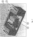
- Figure 7 depicts the installation of a circuit breaker 99 onto the din rail 82 to mount the circuit breaker 99 onto the bottom wall 12b of the bottom housing 12.
- the circuit breaker 99 is tilted to one side and a portion of the bottom of the circuit breaker 99 engages the lip 82b of the din rail 82.
- the circuit breaker is then tilted back to its normal position where it engages the other lip 82b of din rail 82. In this manner, the circuit breaker 99 becomes removably attached to the din rail 82.
- Other types of circuit breakers and electrical devices may be attached to the din rail in the same manner.
- the stopper plate (shown in Figure 6 ) is used to prevent lateral movement of the circuit breaker 99 or other electrical devices and to properly align the terminals of the circuit breaker 99 or other electrical devices with the sidewalls of the bottom housing 12.
- Figure 8 is a perspective view of bottom housing 12 with circuit breaker 99 positioned therein.
- Vertical extending ribs 42 are shown extending outwardly from first sidewall 40 of bottom housing 12.
- Terminal holder assemblies 30, 32, and 34 are shown prior to positioning between vertically extending ribs 42 as shown in Figure 1 .
- Terminal holder auxiliary assembly 36 is also shown prior to positioning between vertically extending ribs 42.
- Figure 9 is a perspective view of bottom housing 12 with circuit breaker 99 positioned therein.
- Terminal holder assemblies 30, 32, and 34 are shown positioned between vertically extending ribs 42 on sidewall 40.
- Terminal holder auxiliary assembly 36 is also shown positioned between vertical extending ribs 42 on sidewall 40.
- Also shown awaiting positioning in the terminal holder assemblies 30, 32, and 34 are contact terminal buses 50, 52, and 54.
- Terminal holder auxiliary assembly 36 is also shown positioned between vertically extending ribs 42.
- Contact terminal bus with flexible wire assembly 56 is also shown awaiting positioning between ribs 42.
- the present embodiments envision the use of a variety of different types of circuit breakers and other electrical components positioned within the enclosure.
- the present embodiments are designed for use with a wide variety of different circuit breakers and components made by a variety of different manufacturers.
- An example of the variety of different types of circuit breakers available and the varying geometries used is illustrated in Figure 10 .
- the present embodiments envision machining/drilling holes into the sidewalls of the bottom housing 12, with the locations of such holes dependent upon the geometry of the particular circuit breaker chosen. The drilling of holes adapted for use with a specific circuit breaker allows the housing to be customized for use with such specific circuit breaker.
- holes are drilled at specified locations in the sidewalls of the bottom housing 12 corresponding to the location of the bus ports of the particular circuit breaker.
- IEC 60079-1/IECEx 60079-1 Electrical apparatus for explosive gas atmospheres, Part 1: Construction and verification test of flameproof enclosures of electrical apparatus
- the holes must be drilled very accurately with tolerances on diameter of +0.02/+0.05mm.
- softer plastics like many thermoplastics, tend to tear when local load concentrations occur.
- Thermoplastics are a good thermal insulator, meaning that the high energy imparted by cutting tools turns into frictional heat that, because it does not dissipate easily, quickly reaches the melting point of many plastics and even the burning point of others.
- Essentially all plastics have heat-distortion limits where the plastics lose rigidity and strength. Therefore, for machining operations, it is beneficial to use special cutting tools and techniques to achieve desired results.
- drills that are not made of high-speed steel or solid carbide should have carbide or diamond tips.
- drills should have highly polished flutes and chrome-plated or nitrided surfaces.
- the drill design preferably has the conventional land, the spiral with regular or slower helix angles (16-30 degrees), the rake with positive angle (0 to +5 degrees), the point angle conventional angles (90-118 degrees), the end angle with conventional values (120-135 degrees), and the lip clearance angle with conventional values (12-18 degrees).
- high-speed or carbide-steel machine reamers will ream accurately sized holes in thermoplastic. It is preferable to use a reamer 0.015-0.126mm larger than the desired hole size to allow for the resiliency of the plastic. Tolerances as close to +/-0.01mm can be held in through holes 15 mm in diameter. Fluted reamers are best for obtaining a good finished surface. In addition, reamer speeds preferably approximate those used for drilling. The amount of material removed per cut will vary with the hardness of the plastic, and although reaming can be dry, it is preferable to use water soluble coolants to produce better finishes.
- the present enclosure is designed to house a plurality of different circuit breakers or other electrical components. Although it could be used to house a single circuit breaker or electrical component, it preferably is designed to house a plurality of such components.
- a 3.5 module design is provided.
- the enclosure may house one two pole circuit breaker and an auxiliary contact. It also may be used with one (pole + neutral) circuit breaker with GFI and an auxiliary contact.
- Figure 11 illustrates the various electrical devices that may be positioned within the enclosure 10. For example, circuit breaker 130 having three poles and one auxiliary contact could be placed in enclosure 10. Similarly GFI breaker 140, motor starter 150, and contactor/relay 160 could also be placed within enclosure 10.
- the enclosure 10 is shown with actuator knob 20 designed for use as an internal actuator mechanism as the enclosure 10 (and knob 20) are designed to be enclosed within stainless steel enclosure 32a or plastic enclosure 32b.
- configuration 118 includes three single pole breakers 118a and an auxiliary contact 118b.
- Configuration 120 includes one two pole breaker 120a, one single pole breaker 120b, and one auxiliary contact 120c.
- Configuration 122 includes one three pole breaker 122a and one auxiliary contact 122b, configuration 124 is a GFI breaker, configuration 126 is a motor starter, and configuration 128 is a contactor/relay.
- Each of the configurations 118, 120, 122, 124, 126, and 128 may be positioned within bottom housing 12, and once top housing 14 is secured to bottom housing 14, a sealed electrical enclosure 10 is created.
- sealed enclosures 10 are shown mounted on an electrical panel 170. It is contemplated that sealed enclosures 10 may be mounted in suitable electrical panels boxes, including stainless steel, plastic, and thin-wall cast panel boxes. Figure 14 shows that sealed enclosures 10 are provided with external actuators, as actuator knobs 20 may be manipulated externally from electrical panel 170.
- bus 200 is shown installed in the enclosure 10.
- bus 200 extends through a drilled hole in sidewall 40 of bottom housing 12 where a first end of bus 200 extends into engagement with contact port 85 of circuit breaker 80.
- a second end of bus 200 is positioned in a location external to the inside of bottom housing 12 and where it engages terminal assembly 30.
- bus 200a extends through a drilled hole in sidewall 40a of bottom housing 12 where a first end of bus 200a extends into engagement with contact port 85a of circuit breaker 80.
- a second end of bus 200a is positioned in a location external to the inside of bottom housing 12 and where it engages terminal assembly 30a.
- Electrical bus 200 has a first end 201 that includes flats 203 for engaging the contact port of a circuit breaker or other electrical device within the sealed electrical enclosure.
- electrical bus 210 has a first end 211 that includes a flexible wire and is adapted for connection to an auxiliary contact within the sealed electrical enclosure.
- Both electrical bus 200 and 210 include a second end 202 and 212 respectively that is shown including a flat section to improve manipulation of the bus during assembly.
- Electrical bus 200 includes two slots 204 that are designed to engage with slots on the ribs of the sidewall of the bottom housing (not shown).
- Electrical bus 210 similarly includes two slots 214 that are designed to engage with slots on the ribs of the sidewall of the bottom housing (not shown).
- the electrical buses 200 and 210 are preferably made of a conductive material such as brass with tinning finish, or a copper strip with nickel plating.
- a screw or other self collapsing locking mechanism on the circuit breaker is used to secure the end of the electrical bus to the circuit breaker.
- electrical bus 200 is shown just prior to positioning through sidewall 40 of bottom housing 12. Hole 95 is shown that has been drilled through sidewall 40 and in alignment with the contact port 85 of circuit breaker 80. The electrical bus is press fit through hole 95 in sidewall 40 and the first end 201 of the electrical bus is moved into engagement with contact port 85 of the circuit breaker 80. A screw may be inserted through aperture 83 of the circuit breaker 80 to secure the first end 201 of the electrical bus 200 within the contact port 85 of circuit breaker 80.
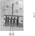
- the flat surface of second end 202 of the electrical bus 200 should be coplanar with the ribs 42 of bottom housing 12 as shown. As shown in Figure 17 , the flat second end 202 of electrical bus 200 is inserted between the ribs 42 of bottom housing 12 and passes through the inwardly directed ridges 230 and 231 that extend from vertical ribs 42.
- FIG. 18 shows the electrical bus 200 properly positioned and connected to circuit breaker 80.
- first end 201 of electrical bus 200 is shown positioned in contact port 85 of circuit breaker 80.
- Electrical bus extends through sidewall 40 of the bottom housing and the second end 202 of the electrical bus 200 is positioned between ribs 42 of the sidewall. The second end 202 has been rotated 90 degrees so that slot 204 is engaged with the ridge 231 extending vertically and inwardly from rib 42.
- Figure 19 shows three electrical buses positioned on each side of the sealed enclosure. First end 202 of each electrical bus is shown with slots 204 in engagement with ridges 230 and 231 on ribs 42. Electrical bus 210 is also shown in proper engagement for connection to an auxiliary contact within the enclosure.
- Figure 20 shows a cutaway view of sealed electrical enclosure 10 with electrical bus 210 extending through sidewall 40 of bottom housing 12 and having a first end 211 with a flexible wire inserted into contact port 182 of auxiliary contact 180.
- a sealed enclosure 310 is shown in Figure 21 in a 9 module design.
- up to 9 different circuit breakers or electrical components could be positioned within the housing.
- terminal assemblies 350, 352, and 354 are shown positioned between vertical ribs 342.
- other embodiments having even more (or less) modules could also be used.
- the following configurations of electrical components could be accommodated including four two pole breakers, three two pole breakers and three auxiliary contacts, three (pole + neutral) compact breakers and GFI and three auxiliary contacts, three three pole breakers, a two pole breaker and GFI, two four pole breakers, two three pole breakers and two auxiliary contacts, two compact four pole breakers and GFI with one auxiliary contact, or one three or four pole breaker and a GFI block of three modules, and an auxiliary contact.
- the embodiments disclosed provide a flame proof enclosure for use in hazardous (classified) areas with the manipulation of the switch external to the enclosure.
- the circuit breakers within the sealed electrical enclosure do not themselves need to be flame proof and can be more easily removed and replaced simply by removing top housing while allowing sealed electrical enclosure to be reused.
- the present invention is shown in a particular configuration for illustrative purposes only.
- the sealed electrical enclosure may have varying geometries to accommodate various sized circuit breakers and electrical components. It is contemplated that the enclosure may be used with circuit breakers skus currently available from ABB. With some possible modification to the geometry of the housing, it is contemplated that the present design would be suitable for use for many different types of available or yet to be released circuit breakers.
- enclosure could be enlarged to house additional circuit breakers and its geometry could be modified to accommodate circuit breakers of varying size.
- embodiments of the sealed enclosure described herein may be used in hazardous (classified) locations such as IEC Zone 1 and Zone 2 environments, as well as Class I, Division 2 and Class I, Zone 1 environments.
Landscapes
- Breakers (AREA)
- Switch Cases, Indication, And Locking (AREA)
Description
- This application relates generally to sealed electrical enclosures for use in hazardous locations for a variety of electrical components, such as circuit breakers, motor switches, GFI devices, and photocells.
- Traditionally, in Europe, in accordance with IEC methodology, each circuit breaker or other electrical device is separately and permanently sealed (often potted in epoxy) to provide a flame proof device. Such circuit breakers are available from Stahl, CEAG, and ATX. Each flame proof sealed circuit breaker or electrical device is then typically placed in a non-metallic or sheet metal enclosure. In the event that a circuit breaker needs to be replaced, the flame proof circuit breaker is removed, and a replacement flame proof circuit breaker installed. A drawback to this methodology is that it is more costly to replace each separately sealed flame proof circuit breakers than it is to replace non-flame proof circuit breakers.
- Alternatively, in North America, to use circuit breakers in a hazardous (classified) area, standard circuit breakers are placed in a cast metal housing such as aluminum, wherein the cast metal housing is bolted shut. In such an arrangement, the circuit breaker switches may be manipulated through a cast metal door that is bolted to the cast metal housing. In North America, this construction is suitable for Class I Division 1 and Class I Division 2 applications. A drawback of this arrangement is that the cast iron enclosures are heavy and cumbersome. Furthermore, it can be time consuming and laborious to remove the often extensive number of bolts from the cast metal housing to access the circuit breakers within. Thus, replacing circuit breakers using enclosures with this construction can be time consuming and costly.
- There has been an increased demand for sealed breakers in North America and around the world. Thus, there is a need to provide an electrical enclosure for use in hazardous (classified) locations that can provide for the removal and replacement of circuit breakers or other electrical components from a reusable electrical enclosure.
-
US 2010/033907 relates to a sealed electrical enclosure used in hazardous locations for enclosing circuit breakers having a bottom housing and a top housing with a labyrinth seal or joint formed therebetween, the bottom housing adapted to receive one or more circuit breakers, a first metal bus extending from a point internal to the bottom housing through a first end wall to a point external thereto, and a second metal bus extending from a point internal to the bottom housing through a second end wall to a point external to thereto, where the first and second metal buses are adapted to contact first and second electrical terminals of a circuit breaker when placed within the bottom housing. - The present application provides a sealed electrical enclosure for use in hazardous locations for enclosing circuit breakers or other electrical components comprising: a bottom housing having a first end wall and a second end wall, a top housing positioned above the bottom housing, a labyrinth joint or serrated joint or combination of both being formed between the bottom housing and the top housing, a first aperture extending through the first end wall and positioned adjacent a first contact terminal of a first circuit breaker when the first circuit breaker is positioned within the bottom housing, the first aperture further including a first metal bus extending through the first aperture and in electrical contact with the first contact terminal and also extending to a point external to the bottom housing, and a second aperture extending through the second end wall and positioned adjacent a second contact terminal of the first circuit breaker when the first circuit breaker is positioned within the bottom housing, the second aperture further including a second metal bus extending through the second aperture and in electrical contact with the second contact terminal and also extending to a point external to the bottom housing, and a first actuating mechanism positioned on the top housing adapted for manipulating a switch of the first circuit breaker, and wherein the top housing is removably secured to the bottom housing to allow for removal and replacement of the first circuit breaker or the first electrical component within the housing.
- Exemplary embodiments of the invention are described herein with reference to the drawings, in which:
-
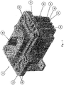
Figure 1 is a perspective view of an embodiment of a sealed electrical enclosure; -
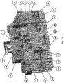
Figure 2 is a cutaway view of an embodiment of the sealed electrical enclosure ofFigure 1 ; -
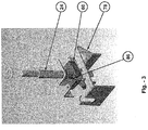
Figure 3 is a perspective view of the actuator mechanism ofFigure 2 ; -
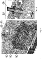
Figure 4 is a cutaway view of a sealed electrical enclosure with an external actuator mechanism; -
Figure 4a is a cutaway close up view of the external actuator mechanism ofFigure 4 ; -
Figure 5 is a perspective view of the bottom housing of the sealed electrical enclosure ofFigure 1 ; -
Figure 5a is a cutaway view of the serrated and labyrinth joint between the top housing and the bottom housing; -
Figure 6 is a cutaway view of a the bottom housing showing placement of a din rail; -
Figure 7 is a perspective cutaway view of a circuit breaker being mounted onto the din rail in the bottom housing of the sealed electrical enclosure ofFigure 1 ; -
Figure 8 is a perspective view of the bottom housing; -
Figure 9 is a perspective view of the bottom housing of the sealed electrical enclosure ofFigure 1 showing positioning of the electrical buses prior to assembly; -
Figure 10 is a view of a variety of various circuit breakers; -
Figure 11 is a perspective view of various electrical components that could be positioned in the sealed electrical enclosure ofFigure 1 ; -
Figure 12 is another perspective view showing various configurations of electrical components that could be positioned in the sealed electrical enclosure; -
Figure 13 is a perspective view showing sealed electrical enclosure positioned within an electrical panel box; -
Figure 14 is a perspective view of sealed electrical enclosures positioned within an electrical panel box with an external actuator mechanism; -
Figure 15a is a perspective view of an electrical bus for use in the sealed electrical enclosure ofFigure 1 ; -
Figure 15b is a perspective view of an electrical bus for use in connecting an auxiliary contact in the sealed enclosure ofFigure 1 ; -
Figure 16 is a cutaway view of the sealed electrical enclosure showing the electrical bus just prior to assembly into the enclosure; -
Figure 17 is a perspective view of the side wall and extending ribs of the bottom housing of the sealed electrical enclosure; -
Figure 18 is a cutaway view of the sealed electrical enclosure showing the placement of the electrical bus through the sidewall an into engagement with the circuit breaker positioned within the bottom housing; -
Figure 19 is a bottom view of the electrical buses positioned within the bottom housing of the sealed electrical enclosure; -
Figure 20 is a cutaway view of the sealed electrical enclosure showing the positioning of the electrical bus through the sidewall and into engagement with the auxiliary contact positioned within the bottom housing; -
Figure 21 is a perspective view of a nine-module embodiment of a sealed electrical enclosure. - Referring to
Figure 1 , a perspective view of sealedelectrical enclosure 10 is shown havingbottom housing 12 andtop housing 14, withtop housing 14 being removably secured tobottom housing 12 usingallenhead screws 22. Of course, the use of allenhead screws is not required, as any other suitable means of removably securingtop housing 14 tobottom housing 12 could be used such as bolts, clips, screws, clamps, latches, etc. Preferablybottom housing 12 andtop housing 14 are comprised of hard non-conductive material such as a plastic or composite material, preferably Solvay IXEF 1022, although IXEF 1521 or Ryton R-4 may also be suitable. - Sealed
electrical enclosure 10 further includes anactuating mechanism knob 20 that allows for the manipulation of the switches of circuit breakers or other electrical components positioned within theenclosure 10. Theactuating mechanism 20 provides for rotary actuation, although linear actuation could be used as well.Enclosure 10 may be used to house various types of circuit breakers and other electrical components such as circuit interrupters, motor switches, GFI devices, and photocells to name a few. Further,enclosure 10 may be used to house either or both IEC and NEC approved products. - As shown in
Figure 1 , contact terminal holder assemblies 30, 32, and 34 are shown positioned between vertically extendingribs 42 positioned on afirst sidewall 40 of theenclosure 10. Circuit breakers or other electrical products may be positioned entirely withinenclosure 10 and electrically connected to electrical terminals in an electrical panel box (not shown). Using the configuration shown, sealedenclosure 10 provides for a flame proof housing for use in IEC Zone 1 and Zone 2, and possibly in other hazardous locations or areas classified by divisions or zones such as Class I, Zone 1, or Class I, Division 2 - With the configuration of sealed
electrical enclosure 10, by removingallenhead screws 22,top housing 14 may be removed frombottom housing 12. As a result, the circuit breakers or other electrical products positioned within theenclosure 10 may be removed and replaced, while allowing sealedelectrical enclosure 10 to be reused. The circuit breakers or other electrical devices may be manipulated by the use ofactuating mechanism knob 20 positioned outside of theelectrical enclosure 10. Thus, theactuating mechanism knob 20 positioned outside of theenclosure 10, allows theenclosure 10 to be positioned within an electrical panel box (not shown), and still allow for the actuating mechanism knob to manipulate the switch of a circuit breaker or other electrical device positioned withinenclosure 10. -
Figure 2 shows a sectional, perspective view of sealedelectrical enclosure 10 withactuating mechanism knob 20 ontop housing 14 wherein theknob 20 is attached toactuator shaft 24 which extends through thetop cover 14 ofenclosure 10 to a point within theenclosure 10.Actuator shaft 24 extends throughlink 60 andactuator block 78. Asknob 20 is rotated, theactuator shaft 24 rotates to causetoggle operator 70 to manipulate theswitch 74 positioned on top of circuit breaker orelectrical device 80 positioned within theenclosure 10. As shown inFigure 2 , the circuit breaker orelectrical device 80 is positioned ondin rail 82 on the bottom ofenclosure 10. Positioned on either side of thedin rail 82 are ventingplates 84. -
Figure 3 shows a close up view of the actuating mechanism shown inFigure 2 . In particular,actuator shaft 24 is shown extending through and connecting withlink 60. When theactuator shaft 24 is rotated, thelink 60 includes a slot positioned aboutswitch manipulator 86 that is in turn positioned onactuator block 78. Rotation oflink 60 causes theswitch manipulator 86 to move in a linear direction which serves to manipulate the switch of the circuit breaker or other electrical device within the enclosure (not shown). -
Figure 2 discloses what can be referred to as an internal actuator mechanism. With an internal actuator mechanism, theelectrical enclosure 10, including theactuating knob 20 is positioned within a distribution panel or enclosure. Because theactuator mechanism knob 20 is positioned within the distribution panel or enclosure, the enclosure has what is referred to as an internal actuator mechanism. Alternatively, as shown inFigure 4 , theelectrical enclosure 10 may include an external actuator mechanism which is designed to have theactuator knob 20 positioned outside the distribution panel orenclosure 27 when theelectrical enclosure 10 is positioned within the distribution panel orenclosure 27. In this embodiment, theactuator shaft 24 extends outwardly from the enclosure 10 a distance sufficient to extend throughdoor 27a of distribution panel orenclosure 27. In this external actuator mechanism embodiment, theknob 20 may be rotated to manipulate the switch of the circuit breaker or otherelectrical device 80 of theelectrical enclosure 10, which is positioned inside the distribution panel orenclosure 27.Figure 4a is a close up cutaway view showingactuator shaft 24 extending throughdoor 27a to the interior of the distribution panel or enclosure, while theknob 20 may be manipulated in a location external to the distribution panel or enclosure. -
Figure 5 shows a perspective view ofbottom housing 12 with acavity 13 for housing circuit breakers or other electrical components.Bottom housing 12 includes a combination of a labyrinth joint and a serrated joint. In particular,bottom housing 12 includesserrations 17 that are designed to engage in a mating relationship with serrations on the bottom surface of the top housing of the enclosure (not shown). In addition,bottom housing 12 includes alabyrinth extension 19 that is designed to engage in a mating relationship with a labyrinth joint channel located on the bottom surface of the top housing of the enclosure (not shown).Figure 5a shows the mating relationship of theserrated teeth 17 between thebottom housing 12 and thetop housing 14 of the enclosure. The portion shown inFigure 5a is a closeup view of the circledsection 65 shown inFigure 2 . In this Figure, five fully engaged serrations are shown, although in some instances fewer or more engaged serrations may be appropriate, and teeth of varying size may be appropriate. In addition to the serrated teeth shown inFigures 5 and5a , this embodiment further includes a labyrinth joint between thebottom housing 12 and thetop housing 14 where thelabyrinth extension 19 of thebottom housing 12 extends into and engages acorresponding labyrinth channel 19a positioned on thetop housing 14. In this manner, with both a labyrinth joint and a serrated joint between thebottom housing 12 and thetop housing 14, a greater deal of protection is provided allowing the device to qualify as an explosion proof housing, and meeting the flame path requirements needed to operate in IEC Zone 1, and Zone 2 environments, and possibly in Class I Division 2 environments, and in Class 1, Zone 1 environments. The enclosure could be provided with preferably only a labyrinth joint, although only a serrated joint, or a combination of a labyrinth joint and a serrated joint may be used. - The next series of Figures shows how to configure, assemble, and mount the circuit breakers or other electrical devices within the enclosure.
Figure 6 is a cutaway view ofbottom housing 12. Two ventingplates 84 are shown positioned on thebottom wall 12b ofbottom housing 12. The ventingplates 84 allow for pressure and heat to dissipate within the enclosure. Ventingplate 84 is preferably formed of a sintered bronze material. Other materials could be used as the vent material such as stainless steel or aluminum depending upon the application. InFigure 6 , there are twoseparate venting plates 84 shown positioned in thebottom wall 12b ofbottom housing 12. However, a single venting plate could also be used, as could additional venting plates. - Turning back to
Figure 6 , two mountingholes 90 are shown onbottom wall 12b positioned between the ventingplates 84. Adin rail 82 is positioned between the venting plates and attached to thebottom wall 12b by use of mountingscrews stopper plate 96 is positioned between mountingscrew 92b anddin rail 82. In this manner, a base comprising the din rail 82 (as well as the stopper plate 96) may be positioned on thebottom wall 12b of thebottom housing 12 to allow for a variety of circuit breakers and other electrical devices to be positioned withincavity 13 of the enclosure. Thedin rail 82 includes oppositely disposedlips 82b that are designed to engage a bottom portion of a circuit breaker or other electrical device for mounting purposes. -
Figure 7 depicts the installation of acircuit breaker 99 onto thedin rail 82 to mount thecircuit breaker 99 onto thebottom wall 12b of thebottom housing 12. In practice, thecircuit breaker 99 is tilted to one side and a portion of the bottom of thecircuit breaker 99 engages thelip 82b of thedin rail 82. The circuit breaker is then tilted back to its normal position where it engages theother lip 82b ofdin rail 82. In this manner, thecircuit breaker 99 becomes removably attached to thedin rail 82. Other types of circuit breakers and electrical devices may be attached to the din rail in the same manner. The stopper plate (shown inFigure 6 ) is used to prevent lateral movement of thecircuit breaker 99 or other electrical devices and to properly align the terminals of thecircuit breaker 99 or other electrical devices with the sidewalls of thebottom housing 12. -
Figure 8 is a perspective view ofbottom housing 12 withcircuit breaker 99 positioned therein. Vertical extendingribs 42 are shown extending outwardly fromfirst sidewall 40 ofbottom housing 12.Terminal holder assemblies ribs 42 as shown inFigure 1 . Terminal holderauxiliary assembly 36 is also shown prior to positioning between vertically extendingribs 42. -
Figure 9 is a perspective view ofbottom housing 12 withcircuit breaker 99 positioned therein.Terminal holder assemblies ribs 42 onsidewall 40. Terminal holderauxiliary assembly 36 is also shown positioned between vertical extendingribs 42 onsidewall 40. Also shown awaiting positioning in theterminal holder assemblies contact terminal buses auxiliary assembly 36 is also shown positioned between vertically extendingribs 42. Contact terminal bus withflexible wire assembly 56 is also shown awaiting positioning betweenribs 42. - The present embodiments envision the use of a variety of different types of circuit breakers and other electrical components positioned within the enclosure. The present embodiments are designed for use with a wide variety of different circuit breakers and components made by a variety of different manufacturers. An example of the variety of different types of circuit breakers available and the varying geometries used is illustrated in
Figure 10 . Given the variety and geometry of the different circuit breakers available, the present embodiments envision machining/drilling holes into the sidewalls of thebottom housing 12, with the locations of such holes dependent upon the geometry of the particular circuit breaker chosen. The drilling of holes adapted for use with a specific circuit breaker allows the housing to be customized for use with such specific circuit breaker. To adapt thebottom housing 12 for use with a particular circuit breaker, holes are drilled at specified locations in the sidewalls of thebottom housing 12 corresponding to the location of the bus ports of the particular circuit breaker. To fulfill the requirements of IEC 60079-1/IECEx 60079-1 (Electrical apparatus for explosive gas atmospheres, Part 1: Construction and verification test of flameproof enclosures of electrical apparatus), the holes must be drilled very accurately with tolerances on diameter of +0.02/+0.05mm. - Softer plastics, like many thermoplastics, tend to tear when local load concentrations occur. Thermoplastics are a good thermal insulator, meaning that the high energy imparted by cutting tools turns into frictional heat that, because it does not dissipate easily, quickly reaches the melting point of many plastics and even the burning point of others. Essentially all plastics have heat-distortion limits where the plastics lose rigidity and strength. Therefore, for machining operations, it is beneficial to use special cutting tools and techniques to achieve desired results.
- For example, drills that are not made of high-speed steel or solid carbide should have carbide or diamond tips. Also, drills should have highly polished flutes and chrome-plated or nitrided surfaces. The drill design preferably has the conventional land, the spiral with regular or slower helix angles (16-30 degrees), the rake with positive angle (0 to +5 degrees), the point angle conventional angles (90-118 degrees), the end angle with conventional values (120-135 degrees), and the lip clearance angle with conventional values (12-18 degrees).
- With regard to reaming, high-speed or carbide-steel machine reamers will ream accurately sized holes in thermoplastic. It is preferable to use a reamer 0.015-0.126mm larger than the desired hole size to allow for the resiliency of the plastic. Tolerances as close to +/-0.01mm can be held in through holes 15 mm in diameter. Fluted reamers are best for obtaining a good finished surface. In addition, reamer speeds preferably approximate those used for drilling. The amount of material removed per cut will vary with the hardness of the plastic, and although reaming can be dry, it is preferable to use water soluble coolants to produce better finishes.
- The present enclosure is designed to house a plurality of different circuit breakers or other electrical components. Although it could be used to house a single circuit breaker or electrical component, it preferably is designed to house a plurality of such components. In one embodiment, a 3.5 module design is provided. In the 3.5 module design, the enclosure may house one two pole circuit breaker and an auxiliary contact. It also may be used with one (pole + neutral) circuit breaker with GFI and an auxiliary contact.
Figure 11 illustrates the various electrical devices that may be positioned within theenclosure 10. For example,circuit breaker 130 having three poles and one auxiliary contact could be placed inenclosure 10. SimilarlyGFI breaker 140,motor starter 150, and contactor/relay 160 could also be placed withinenclosure 10. InFigure 11 , theenclosure 10 is shown withactuator knob 20 designed for use as an internal actuator mechanism as the enclosure 10 (and knob 20) are designed to be enclosed withinstainless steel enclosure 32a orplastic enclosure 32b. - In
Figure 12 , another illustration is shown regarding the various configurations of circuit breakers and electrical components that can be positioned within the sealed breaker. For example,configuration 118 includes threesingle pole breakers 118a and anauxiliary contact 118b.Configuration 120 includes one twopole breaker 120a, onesingle pole breaker 120b, and oneauxiliary contact 120c.Configuration 122 includes one threepole breaker 122a and oneauxiliary contact 122b,configuration 124 is a GFI breaker,configuration 126 is a motor starter, andconfiguration 128 is a contactor/relay. Each of theconfigurations bottom housing 12, and oncetop housing 14 is secured tobottom housing 14, a sealedelectrical enclosure 10 is created. InFigure 13 , eight different sealeddevices 10 are shown mounted on anelectrical panel 170. It is contemplated that sealedenclosures 10 may be mounted in suitable electrical panels boxes, including stainless steel, plastic, and thin-wall cast panel boxes.Figure 14 shows that sealedenclosures 10 are provided with external actuators, as actuator knobs 20 may be manipulated externally fromelectrical panel 170. - Returning now back to the assembly and installation of the circuit breakers within the
enclosure 10, once the determination is made regarding which circuit breakers or other electrical components will be positioned within the enclosure and removably secured to the din rail positioned on the bottom wall of the bottom housing, then the holes for the buses must be drilled in the locations associated with the geometry for that particular circuit breaker or other electrical device. - Once the holes for the buses are drilled, then the buses must be installed. Referring back to
Figure 2 ,bus 200 is shown installed in theenclosure 10. In particular,bus 200 extends through a drilled hole insidewall 40 ofbottom housing 12 where a first end ofbus 200 extends into engagement withcontact port 85 ofcircuit breaker 80. A second end ofbus 200 is positioned in a location external to the inside ofbottom housing 12 and where it engagesterminal assembly 30. A similar configuration exists on theopposite wall 40a of thebottom housing 12, wherebus 200a extends through a drilled hole insidewall 40a ofbottom housing 12 where a first end ofbus 200a extends into engagement withcontact port 85a ofcircuit breaker 80. A second end ofbus 200a is positioned in a location external to the inside ofbottom housing 12 and where it engagesterminal assembly 30a. - In
Figures 15a and 15b , theelectrical buses Electrical bus 200 has afirst end 201 that includesflats 203 for engaging the contact port of a circuit breaker or other electrical device within the sealed electrical enclosure. Similarly,electrical bus 210 has afirst end 211 that includes a flexible wire and is adapted for connection to an auxiliary contact within the sealed electrical enclosure. Bothelectrical bus second end Electrical bus 200 includes twoslots 204 that are designed to engage with slots on the ribs of the sidewall of the bottom housing (not shown).Electrical bus 210 similarly includes twoslots 214 that are designed to engage with slots on the ribs of the sidewall of the bottom housing (not shown). Theelectrical buses - In
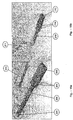
Figure 16 ,electrical bus 200 is shown just prior to positioning throughsidewall 40 ofbottom housing 12.Hole 95 is shown that has been drilled throughsidewall 40 and in alignment with thecontact port 85 ofcircuit breaker 80. The electrical bus is press fit throughhole 95 insidewall 40 and thefirst end 201 of the electrical bus is moved into engagement withcontact port 85 of thecircuit breaker 80. A screw may be inserted throughaperture 83 of thecircuit breaker 80 to secure thefirst end 201 of theelectrical bus 200 within thecontact port 85 ofcircuit breaker 80. When inserting theelectrical bus 200, the flat surface ofsecond end 202 of theelectrical bus 200 should be coplanar with theribs 42 ofbottom housing 12 as shown. As shown inFigure 17 , the flatsecond end 202 ofelectrical bus 200 is inserted between theribs 42 ofbottom housing 12 and passes through the inwardly directedridges vertical ribs 42. - Once the first end of the bus is inserted into the contact port of the circuit breaker, then the electrical bus should be rotated 90 degrees so that the
slots 204 engage withridges Figure 18 shows theelectrical bus 200 properly positioned and connected tocircuit breaker 80. In particular,first end 201 ofelectrical bus 200 is shown positioned incontact port 85 ofcircuit breaker 80. Electrical bus extends throughsidewall 40 of the bottom housing and thesecond end 202 of theelectrical bus 200 is positioned betweenribs 42 of the sidewall. Thesecond end 202 has been rotated 90 degrees so thatslot 204 is engaged with theridge 231 extending vertically and inwardly fromrib 42. -
Figure 19 shows three electrical buses positioned on each side of the sealed enclosure.First end 202 of each electrical bus is shown withslots 204 in engagement withridges ribs 42.Electrical bus 210 is also shown in proper engagement for connection to an auxiliary contact within the enclosure.Figure 20 shows a cutaway view of sealedelectrical enclosure 10 withelectrical bus 210 extending throughsidewall 40 ofbottom housing 12 and having afirst end 211 with a flexible wire inserted intocontact port 182 ofauxiliary contact 180. - In an alternate embodiment, a sealed
enclosure 310 is shown inFigure 21 in a 9 module design. In this embodiment, up to 9 different circuit breakers or electrical components could be positioned within the housing. As shown inFigure 21 , there are nine sets ofvertical ribs 342 on the outer surface of the bottom housing of the enclosure. InFigure 21 ,terminal assemblies vertical ribs 342. Of course, other embodiments having even more (or less) modules could also be used. With the 9 module design, the following configurations of electrical components could be accommodated including four two pole breakers, three two pole breakers and three auxiliary contacts, three (pole + neutral) compact breakers and GFI and three auxiliary contacts, three three pole breakers, a two pole breaker and GFI, two four pole breakers, two three pole breakers and two auxiliary contacts, two compact four pole breakers and GFI with one auxiliary contact, or one three or four pole breaker and a GFI block of three modules, and an auxiliary contact. - The embodiments disclosed provide a flame proof enclosure for use in hazardous (classified) areas with the manipulation of the switch external to the enclosure. With such a design, the circuit breakers within the sealed electrical enclosure do not themselves need to be flame proof and can be more easily removed and replaced simply by removing top housing while allowing sealed electrical enclosure to be reused.
- The present invention is shown in a particular configuration for illustrative purposes only. The sealed electrical enclosure may have varying geometries to accommodate various sized circuit breakers and electrical components. It is contemplated that the enclosure may be used with circuit breakers skus currently available from ABB. With some possible modification to the geometry of the housing, it is contemplated that the present design would be suitable for use for many different types of available or yet to be released circuit breakers.
- It will be appreciated that the enclosure could be enlarged to house additional circuit breakers and its geometry could be modified to accommodate circuit breakers of varying size.
- It is contemplated that embodiments of the sealed enclosure described herein may be used in hazardous (classified) locations such as IEC Zone 1 and Zone 2 environments, as well as Class I, Division 2 and Class I, Zone 1 environments.
- While certain features and embodiments of the present application have been described in detail herein, it is to be understood that the application encompasses all modifications and enhancements within the scope of the following claims. Further, in method claims there is no requirement as to the order of the steps unless specifically stated.
Claims (13)
- A sealed electrical enclosure (10) for use in hazardous locations for enclosing circuit breakers or other electrical components comprising:a bottom housing (12) having a first end wall (40) and a second end wall (40a) opposite the first end wall (40);a top housing (14) positioned above the bottom housing (12);a labyrinth joint or serrated joint or combination of both being formed between the bottom housing (12) and the top housing (14);the bottom housing (12) adapted to receive a first circuit breaker (80) and a first electrical component (140, 150, or 160);a first aperture (95) extending through the first end wall (40), the first aperture (95) further including a first contact terminal bus (200) extending through the first aperture (95) and which may be in electrical contact with a first contact terminal (85) of a first circuit breaker (80) when the first circuit breaker (80) is positioned within the bottom housing (12), the first terminal bus (200) also extending to a point external to the bottom housing (12);a second aperture extending through the second end wall (40a), the second aperture further including a second contact terminal bus (200a) extending through the second aperture and which may be in electrical contact with a second contact terminal (85a) of the first circuit breaker (80) when the first circuit breaker (80) is positioned within the bottom housing (12), the second contact terminal bus (200a) also extending to a point external to the bottom housing (12);a first actuating mechanism (20) positioned on the top housing (14) adapted for manipulating a switch (74) of the first circuit breaker (80);wherein the top housing (14) is removably secured to the bottom housing (12) to allow for removal and replacement of the first circuit breaker (80) or the first electrical component within the housing;characterized in that:the first (95) and second apertures are machined apertures;the first contact terminal bus (200) is configured to be positioned through the first aperture (95); andthe second contact terminal bus (200a) is configured to be positioned through the second aperture.
- The sealed electrical enclosure of claim 1, wherein a labyrinth joint (19, 19a) is formed between the bottom housing (12) and the top housing (14).
- The sealed electrical enclosure of claim 1, wherein a serrated joint (17) is formed between the bottom housing (12) and the top housing (14).
- The sealed electrical enclosure of claim 1, further including a third metal bus (52) extending from a point internal to the bottom housing (12) through the first end wall (40) to a point external to the bottom housing (12);
a fourth metal bus extending from a point internal to the bottom housing through the second end wall (40a) to a point external to the bottom housing (12);
where the third metal bus and the fourth metal bus are adapted to contact the first and second electrical terminals of a second circuit breaker when placed within the bottom housing. - The sealed electrical enclosure of claim 1, wherein vertical ribs (42) extend down at least a portion of the first end wall (40), and vertical ribs extend down at least a portion of the second end wall (40a).
- The sealed electrical enclosure of claim 5, wherein a first terminal assembly (30) is positioned between ribs (42) on the first end wall (40), and a second terminal assembly is positioned between ribs on the second end wall.
- The sealed electrical enclosure of claim 5, wherein a first vertical ridge (230) extends inwardly from one of the ribs (42) on the first end wall (40) and a second vertical ridge (231) extends inwardly from an adjacent rib (42) on the first end wall (40) towards the first vertical ridge (230), and wherein a second end of the first metal bus (200) includes a first slot (204) that engages the first vertical ridge (230) and a second slot (204) that engages the second vertical ridge (231) when the first metal bus (200) is positioned through the first end wall (40).
- The sealed electrical enclosure of claim 1, further comprising the first circuit breaker (80) wherein the first circuit breaker (80) is positioned within the bottom housing (12) and wherein the first metal bus (200) extends through the first aperture (95) drilled in the first end wall (40) that is in alignment with the first electrical contact (85) of the first circuit breaker (80), and the second metal bus (200a) extends through the second aperture drilled in the second end wall (40a) that is in alignment with the second electrical contact (85a) of the first circuit breaker (80).
- The sealed electrical enclosure of claim 1, further including:the first circuit breaker (80) wherein the first circuit breaker (80) is positioned within the bottom housing (12);a second circuit breaker wherein the second circuit breaker is positioned within the bottom housing (12);a third metal bus (52) extending from a point internal to the bottom housing (12) through the first end wall (40) to a point external to the bottom housing (12); anda fourth metal bus extending from a point internal to the bottom housing (12) through the second end wall to a point external to the bottom housing (12);where the third metal bus and the fourth metal bus are in contact with first and second electrical terminals of the second circuit breaker, and whereinthe first metal bus (200) extends through the first aperture (95) drilled in the first end wall (40) that is in alignment with the first electrical contact (85) of the first circuit breaker (80), and the second metal bus (200a) extends through the second aperture drilled in the second end wall (40a) that is in alignment with the second electrical contact (85a) of the first circuit breaker (80), and the third metal bus (52) extends through a third aperture drilled in the first end wall (40) that is in alignment with the first electrical contact of the second circuit breaker, and the fourth metal bus extends through a fourth aperture drilled in the second end wall (40a) that is in alignment with the second electrical contact of the second circuit breaker.
- The sealed electrical enclosure of claim 1, further including a third metal bus (52) extending from a point internal to the bottom housing (12) through the first end wall (40) to a point external to the bottom housing (12);
a fourth metal bus extending from a point internal to the bottom housing (12) through the second end wall (40a) to a point external to the bottom housing (12);
where the third metal bus and the fourth metal bus are adapted to contact the first and second electrical terminals of an auxiliary contact when placed within the bottom housing (12). - A method of positioning a circuit breaker or other electrical component within a sealed electrical enclosure comprising the steps of:providing a bottom housing (12) having a first end wall (40) and a second end wall (40a) opposite the first end wall (40);providing a top housing (14) removably positioned above the bottom housing (12);forming a serrated joint (17) between the bottom housing (12) and the top housing (14) when the top housing (14) is placed over the bottom housing (12);positioning a first circuit breaker (80) or electrical component in the bottom housing (12);drilling a first aperture (95) through the first end wall (40) in a position adjacent to a first contact terminal (85) of the first circuit breaker (80) or electrical component;positioning a first metal bus (200) through the first aperture (95) and into electrical contact with the first contact terminal (85);drilling a second aperture through the second end wall (40a) in a position adjacent to a second contact terminal (85a) of the first circuit breaker (80) or electrical component;positioning a second metal bus (200a) through the second aperture and into electrical contact with the second contact terminal (85a),wherein the first and second metal buses (200, 200a) extend to a point external to the bottom housing (12) to allow for further electrical connection,providing a first actuating mechanism (20) positioned on the top housing (14) adapted for manipulating a switch (74) of the first circuit breaker (80), andsecuring the top housing (14) to the bottom housing (12).
- The method of claim 11 wherein the step of forming a serrated joint (17) further includes the formation of a labyrinth joint (19, 19a) when the top housing (14) is placed over the bottom housing (12).
- The method of claim 11 further including the steps of:positioning a second circuit breaker or electrical component in the bottom housing;drilling a third aperture through the first end wall (40) in a position adjacent to a first contact terminal of the second circuit breaker or electrical component;positioning a third metal bus (52) through the third aperture and into electrical contact with the first contact terminal of the second circuit breaker or electrical component;drilling a fourth aperture through the second end wall (40a) in a position adjacent to a second contact terminal of the second circuit breaker or electrical component;positioning a fourth metal bus through the fourth aperture and into electrical contact with the second contact terminal of the second circuit breaker or electrical component,wherein the third and fourth metal buses extend to a point external to the bottom housing (12) to allow for further electrical connection.
Applications Claiming Priority (2)
| Application Number | Priority Date | Filing Date | Title |
|---|---|---|---|
| IN864MU2010 | 2010-03-26 | ||
| PCT/US2010/036442 WO2011119176A1 (en) | 2010-03-26 | 2010-05-27 | Sealed circuit breaker |
Publications (2)
| Publication Number | Publication Date |
|---|---|
| EP2550669A1 EP2550669A1 (en) | 2013-01-30 |
| EP2550669B1 true EP2550669B1 (en) | 2018-10-17 |
Family
ID=43085926
Family Applications (1)
| Application Number | Title | Priority Date | Filing Date |
|---|---|---|---|
| EP10727538.0A Active EP2550669B1 (en) | 2010-03-26 | 2010-05-27 | Sealed circuit breaker |
Country Status (4)
| Country | Link |
|---|---|
| EP (1) | EP2550669B1 (en) |
| CN (1) | CN102959663B (en) |
| CA (1) | CA2794027C (en) |
| WO (1) | WO2011119176A1 (en) |
Families Citing this family (3)
| Publication number | Priority date | Publication date | Assignee | Title |
|---|---|---|---|---|
| DE102013210208A1 (en) | 2013-05-31 | 2014-12-04 | Tyco Electronics Amp Gmbh | Switching contact chamber sealing |
| EP3188329A1 (en) * | 2015-12-30 | 2017-07-05 | Bomar S.A. w upadlosci ukladowej | Switching device |
| CN115954234A (en) * | 2022-11-18 | 2023-04-11 | 浙江天正电气股份有限公司 | An explosion-proof circuit breaker and its assembly process |
Family Cites Families (4)
| Publication number | Priority date | Publication date | Assignee | Title |
|---|---|---|---|---|
| FR2622734B1 (en) * | 1987-11-04 | 1994-03-18 | Legrand | HOUSING FOR CUTTING APPARATUS, IN PARTICULAR CIRCUIT-BREAKER OR SWITCH, FOR USE IN EXPLOSIVE ATMOSPHERE |
| DE8805069U1 (en) * | 1988-04-16 | 1988-07-14 | BBC Brown Boveri AG, 6800 Mannheim | Explosion-proof electrical installation device |
| DE502006001382D1 (en) * | 2006-01-11 | 2008-10-02 | Siemens Ag | Electrical device with elimination of the load circuit in potentially explosive environments |
| US7907389B2 (en) * | 2008-08-06 | 2011-03-15 | Egs Electrical Group Llc | Sealed circuit breaker |
-
2010
- 2010-05-27 EP EP10727538.0A patent/EP2550669B1/en active Active
- 2010-05-27 WO PCT/US2010/036442 patent/WO2011119176A1/en not_active Ceased
- 2010-05-27 CA CA2794027A patent/CA2794027C/en active Active
- 2010-05-27 CN CN201080067035.7A patent/CN102959663B/en active Active
Non-Patent Citations (1)
| Title |
|---|
| None * |
Also Published As
| Publication number | Publication date |
|---|---|
| CA2794027C (en) | 2014-10-21 |
| CA2794027A1 (en) | 2011-09-29 |
| EP2550669A1 (en) | 2013-01-30 |
| CN102959663A (en) | 2013-03-06 |
| CN102959663B (en) | 2016-04-20 |
| WO2011119176A1 (en) | 2011-09-29 |
Similar Documents
| Publication | Publication Date | Title |
|---|---|---|
| US8508917B2 (en) | Sealed circuit breaker | |
| CA2639500C (en) | Sealed circuit breaker | |
| US8497424B2 (en) | Universal box system | |
| EP3357136B1 (en) | Sealed modular power distribution apparatus | |
| KR100964260B1 (en) | Circuit breaker | |
| US8593791B2 (en) | Sealed circuit breaker | |
| CA2794027C (en) | Sealed circuit breaker | |
| US6784393B2 (en) | Arc quenching device for low-voltage switching devices | |
| JP2021114803A (en) | Electric connection box and structure for covering electrical connection place | |
| CN120834529B (en) | Bus duct plugging device | |
| CN102438415B (en) | For order and signal instrument are fixed to the installation unit on panel | |
| EP2306591A1 (en) | Connector module and plug-in module system | |
| US10485122B2 (en) | Electrically insulative case including frame having plurality of possible orientations | |
| JP4291036B2 (en) | Circuit breakers and distribution boards | |
| EP3065157B1 (en) | Circuit breaker assembly including a circuit breaker connector member | |
| EP4184547B1 (en) | Fuse module with clamped fuse installation | |
| CN1130741C (en) | Safety switch | |
| JP6751917B2 (en) | Switch and distribution board | |
| CN223598638U (en) | A type of cover | |
| US20250323459A1 (en) | Waterproof quick coupling mechanism for switch device | |
| KR100474381B1 (en) | Instant trip device of mccb | |
| CN121601970A (en) | Battery pack and energy storage cabinet | |
| CN122029630A (en) | Circuit breakers for wiring | |
| WO2019161519A1 (en) | Switch device for electrical power distribution systems | |
| KR20100028871A (en) | Parts of box for automobile |
Legal Events
| Date | Code | Title | Description |
|---|---|---|---|
| PUAI | Public reference made under article 153(3) epc to a published international application that has entered the european phase |
Free format text: ORIGINAL CODE: 0009012 |
|
| 17P | Request for examination filed |
Effective date: 20121025 |
|
| AK | Designated contracting states |
Kind code of ref document: A1 Designated state(s): AL AT BE BG CH CY CZ DE DK EE ES FI FR GB GR HR HU IE IS IT LI LT LU LV MC MK MT NL NO PL PT RO SE SI SK SM TR |
|
| RIN1 | Information on inventor provided before grant (corrected) |
Inventor name: RUS, VILIAN Inventor name: KANOLE, YOGESH Inventor name: NADGERI, VIJAY |
|
| DAX | Request for extension of the european patent (deleted) | ||
| RAP1 | Party data changed (applicant data changed or rights of an application transferred) |
Owner name: APPLETON GRP LLC |
|
| STAA | Information on the status of an ep patent application or granted ep patent |
Free format text: STATUS: EXAMINATION IS IN PROGRESS |
|
| 17Q | First examination report despatched |
Effective date: 20171018 |
|
| RIC1 | Information provided on ipc code assigned before grant |
Ipc: H01H 71/02 20060101ALN20180309BHEP Ipc: H01H 9/04 20060101AFI20180309BHEP |
|
| GRAP | Despatch of communication of intention to grant a patent |
Free format text: ORIGINAL CODE: EPIDOSNIGR1 |
|
| RIC1 | Information provided on ipc code assigned before grant |
Ipc: H01H 71/02 20060101ALN20180326BHEP Ipc: H01H 9/04 20060101AFI20180326BHEP |
|
| STAA | Information on the status of an ep patent application or granted ep patent |
Free format text: STATUS: GRANT OF PATENT IS INTENDED |
|
| RIC1 | Information provided on ipc code assigned before grant |
Ipc: H01H 71/02 20060101ALN20180413BHEP Ipc: H01H 9/04 20060101AFI20180413BHEP |
|
| INTG | Intention to grant announced |
Effective date: 20180503 |
|
| RIN1 | Information on inventor provided before grant (corrected) |
Inventor name: NADGERI, VIJAY Inventor name: KANOLE, YOGESH Inventor name: RUS, VILIAN |
|
| GRAS | Grant fee paid |
Free format text: ORIGINAL CODE: EPIDOSNIGR3 |
|
| GRAA | (expected) grant |
Free format text: ORIGINAL CODE: 0009210 |
|
| STAA | Information on the status of an ep patent application or granted ep patent |
Free format text: STATUS: THE PATENT HAS BEEN GRANTED |
|
| AK | Designated contracting states |
Kind code of ref document: B1 Designated state(s): AL AT BE BG CH CY CZ DE DK EE ES FI FR GB GR HR HU IE IS IT LI LT LU LV MC MK MT NL NO PL PT RO SE SI SK SM TR |
|
| REG | Reference to a national code |
Ref country code: GB Ref legal event code: FG4D |
|
| RIN1 | Information on inventor provided before grant (corrected) |
Inventor name: KANOLE, YOGESH Inventor name: RUS, VILIAN Inventor name: NADGERI, VIJAY |
|
| REG | Reference to a national code |
Ref country code: CH Ref legal event code: EP |
|
| REG | Reference to a national code |
Ref country code: IE Ref legal event code: FG4D |
|
| REG | Reference to a national code |
Ref country code: DE Ref legal event code: R096 Ref document number: 602010054388 Country of ref document: DE Ref country code: AT Ref legal event code: REF Ref document number: 1054959 Country of ref document: AT Kind code of ref document: T Effective date: 20181115 |
|
| REG | Reference to a national code |
Ref country code: NL Ref legal event code: MP Effective date: 20181017 |
|
| REG | Reference to a national code |
Ref country code: LT Ref legal event code: MG4D |
|
| REG | Reference to a national code |
Ref country code: AT Ref legal event code: MK05 Ref document number: 1054959 Country of ref document: AT Kind code of ref document: T Effective date: 20181017 |
|
| PG25 | Lapsed in a contracting state [announced via postgrant information from national office to epo] |
Ref country code: NL Free format text: LAPSE BECAUSE OF FAILURE TO SUBMIT A TRANSLATION OF THE DESCRIPTION OR TO PAY THE FEE WITHIN THE PRESCRIBED TIME-LIMIT Effective date: 20181017 |
|
| PG25 | Lapsed in a contracting state [announced via postgrant information from national office to epo] |
Ref country code: LV Free format text: LAPSE BECAUSE OF FAILURE TO SUBMIT A TRANSLATION OF THE DESCRIPTION OR TO PAY THE FEE WITHIN THE PRESCRIBED TIME-LIMIT Effective date: 20181017 Ref country code: AT Free format text: LAPSE BECAUSE OF FAILURE TO SUBMIT A TRANSLATION OF THE DESCRIPTION OR TO PAY THE FEE WITHIN THE PRESCRIBED TIME-LIMIT Effective date: 20181017 Ref country code: FI Free format text: LAPSE BECAUSE OF FAILURE TO SUBMIT A TRANSLATION OF THE DESCRIPTION OR TO PAY THE FEE WITHIN THE PRESCRIBED TIME-LIMIT Effective date: 20181017 Ref country code: NO Free format text: LAPSE BECAUSE OF FAILURE TO SUBMIT A TRANSLATION OF THE DESCRIPTION OR TO PAY THE FEE WITHIN THE PRESCRIBED TIME-LIMIT Effective date: 20190117 Ref country code: BG Free format text: LAPSE BECAUSE OF FAILURE TO SUBMIT A TRANSLATION OF THE DESCRIPTION OR TO PAY THE FEE WITHIN THE PRESCRIBED TIME-LIMIT Effective date: 20190117 Ref country code: PL Free format text: LAPSE BECAUSE OF FAILURE TO SUBMIT A TRANSLATION OF THE DESCRIPTION OR TO PAY THE FEE WITHIN THE PRESCRIBED TIME-LIMIT Effective date: 20181017 Ref country code: HR Free format text: LAPSE BECAUSE OF FAILURE TO SUBMIT A TRANSLATION OF THE DESCRIPTION OR TO PAY THE FEE WITHIN THE PRESCRIBED TIME-LIMIT Effective date: 20181017 Ref country code: IS Free format text: LAPSE BECAUSE OF FAILURE TO SUBMIT A TRANSLATION OF THE DESCRIPTION OR TO PAY THE FEE WITHIN THE PRESCRIBED TIME-LIMIT Effective date: 20190217 Ref country code: LT Free format text: LAPSE BECAUSE OF FAILURE TO SUBMIT A TRANSLATION OF THE DESCRIPTION OR TO PAY THE FEE WITHIN THE PRESCRIBED TIME-LIMIT Effective date: 20181017 Ref country code: ES Free format text: LAPSE BECAUSE OF FAILURE TO SUBMIT A TRANSLATION OF THE DESCRIPTION OR TO PAY THE FEE WITHIN THE PRESCRIBED TIME-LIMIT Effective date: 20181017 |
|
| PG25 | Lapsed in a contracting state [announced via postgrant information from national office to epo] |
Ref country code: SE Free format text: LAPSE BECAUSE OF FAILURE TO SUBMIT A TRANSLATION OF THE DESCRIPTION OR TO PAY THE FEE WITHIN THE PRESCRIBED TIME-LIMIT Effective date: 20181017 Ref country code: PT Free format text: LAPSE BECAUSE OF FAILURE TO SUBMIT A TRANSLATION OF THE DESCRIPTION OR TO PAY THE FEE WITHIN THE PRESCRIBED TIME-LIMIT Effective date: 20190217 Ref country code: GR Free format text: LAPSE BECAUSE OF FAILURE TO SUBMIT A TRANSLATION OF THE DESCRIPTION OR TO PAY THE FEE WITHIN THE PRESCRIBED TIME-LIMIT Effective date: 20190118 Ref country code: AL Free format text: LAPSE BECAUSE OF FAILURE TO SUBMIT A TRANSLATION OF THE DESCRIPTION OR TO PAY THE FEE WITHIN THE PRESCRIBED TIME-LIMIT Effective date: 20181017 |
|
| REG | Reference to a national code |
Ref country code: DE Ref legal event code: R097 Ref document number: 602010054388 Country of ref document: DE |
|
| PG25 | Lapsed in a contracting state [announced via postgrant information from national office to epo] |
Ref country code: CZ Free format text: LAPSE BECAUSE OF FAILURE TO SUBMIT A TRANSLATION OF THE DESCRIPTION OR TO PAY THE FEE WITHIN THE PRESCRIBED TIME-LIMIT Effective date: 20181017 Ref country code: IT Free format text: LAPSE BECAUSE OF FAILURE TO SUBMIT A TRANSLATION OF THE DESCRIPTION OR TO PAY THE FEE WITHIN THE PRESCRIBED TIME-LIMIT Effective date: 20181017 Ref country code: DK Free format text: LAPSE BECAUSE OF FAILURE TO SUBMIT A TRANSLATION OF THE DESCRIPTION OR TO PAY THE FEE WITHIN THE PRESCRIBED TIME-LIMIT Effective date: 20181017 |
|
| PLBE | No opposition filed within time limit |
Free format text: ORIGINAL CODE: 0009261 |
|
| STAA | Information on the status of an ep patent application or granted ep patent |
Free format text: STATUS: NO OPPOSITION FILED WITHIN TIME LIMIT |
|
| PG25 | Lapsed in a contracting state [announced via postgrant information from national office to epo] |
Ref country code: SM Free format text: LAPSE BECAUSE OF FAILURE TO SUBMIT A TRANSLATION OF THE DESCRIPTION OR TO PAY THE FEE WITHIN THE PRESCRIBED TIME-LIMIT Effective date: 20181017 Ref country code: RO Free format text: LAPSE BECAUSE OF FAILURE TO SUBMIT A TRANSLATION OF THE DESCRIPTION OR TO PAY THE FEE WITHIN THE PRESCRIBED TIME-LIMIT Effective date: 20181017 Ref country code: SK Free format text: LAPSE BECAUSE OF FAILURE TO SUBMIT A TRANSLATION OF THE DESCRIPTION OR TO PAY THE FEE WITHIN THE PRESCRIBED TIME-LIMIT Effective date: 20181017 Ref country code: EE Free format text: LAPSE BECAUSE OF FAILURE TO SUBMIT A TRANSLATION OF THE DESCRIPTION OR TO PAY THE FEE WITHIN THE PRESCRIBED TIME-LIMIT Effective date: 20181017 |
|
| 26N | No opposition filed |
Effective date: 20190718 |
|
| PG25 | Lapsed in a contracting state [announced via postgrant information from national office to epo] |
Ref country code: SI Free format text: LAPSE BECAUSE OF FAILURE TO SUBMIT A TRANSLATION OF THE DESCRIPTION OR TO PAY THE FEE WITHIN THE PRESCRIBED TIME-LIMIT Effective date: 20181017 |
|
| REG | Reference to a national code |
Ref country code: CH Ref legal event code: PL |
|
| PG25 | Lapsed in a contracting state [announced via postgrant information from national office to epo] |
Ref country code: MC Free format text: LAPSE BECAUSE OF FAILURE TO SUBMIT A TRANSLATION OF THE DESCRIPTION OR TO PAY THE FEE WITHIN THE PRESCRIBED TIME-LIMIT Effective date: 20181017 Ref country code: LI Free format text: LAPSE BECAUSE OF NON-PAYMENT OF DUE FEES Effective date: 20190531 Ref country code: CH Free format text: LAPSE BECAUSE OF NON-PAYMENT OF DUE FEES Effective date: 20190531 |
|
| REG | Reference to a national code |
Ref country code: BE Ref legal event code: MM Effective date: 20190531 |
|
| PG25 | Lapsed in a contracting state [announced via postgrant information from national office to epo] |
Ref country code: LU Free format text: LAPSE BECAUSE OF NON-PAYMENT OF DUE FEES Effective date: 20190527 |
|
| PG25 | Lapsed in a contracting state [announced via postgrant information from national office to epo] |
Ref country code: TR Free format text: LAPSE BECAUSE OF FAILURE TO SUBMIT A TRANSLATION OF THE DESCRIPTION OR TO PAY THE FEE WITHIN THE PRESCRIBED TIME-LIMIT Effective date: 20181017 |
|
| PG25 | Lapsed in a contracting state [announced via postgrant information from national office to epo] |
Ref country code: IE Free format text: LAPSE BECAUSE OF NON-PAYMENT OF DUE FEES Effective date: 20190527 |
|
| PG25 | Lapsed in a contracting state [announced via postgrant information from national office to epo] |
Ref country code: BE Free format text: LAPSE BECAUSE OF NON-PAYMENT OF DUE FEES Effective date: 20190531 |
|
| PG25 | Lapsed in a contracting state [announced via postgrant information from national office to epo] |
Ref country code: CY Free format text: LAPSE BECAUSE OF FAILURE TO SUBMIT A TRANSLATION OF THE DESCRIPTION OR TO PAY THE FEE WITHIN THE PRESCRIBED TIME-LIMIT Effective date: 20181017 |
|
| PG25 | Lapsed in a contracting state [announced via postgrant information from national office to epo] |
Ref country code: MT Free format text: LAPSE BECAUSE OF FAILURE TO SUBMIT A TRANSLATION OF THE DESCRIPTION OR TO PAY THE FEE WITHIN THE PRESCRIBED TIME-LIMIT Effective date: 20181017 Ref country code: HU Free format text: LAPSE BECAUSE OF FAILURE TO SUBMIT A TRANSLATION OF THE DESCRIPTION OR TO PAY THE FEE WITHIN THE PRESCRIBED TIME-LIMIT; INVALID AB INITIO Effective date: 20100527 |
|
| PG25 | Lapsed in a contracting state [announced via postgrant information from national office to epo] |
Ref country code: MK Free format text: LAPSE BECAUSE OF FAILURE TO SUBMIT A TRANSLATION OF THE DESCRIPTION OR TO PAY THE FEE WITHIN THE PRESCRIBED TIME-LIMIT Effective date: 20181017 |
|
| PGFP | Annual fee paid to national office [announced via postgrant information from national office to epo] |
Ref country code: DE Payment date: 20250423 Year of fee payment: 16 |
|
| PGFP | Annual fee paid to national office [announced via postgrant information from national office to epo] |
Ref country code: GB Payment date: 20250423 Year of fee payment: 16 |
|
| PGFP | Annual fee paid to national office [announced via postgrant information from national office to epo] |
Ref country code: FR Payment date: 20250423 Year of fee payment: 16 |