EP2550436B1 - Heat engines with cascade cycles - Google Patents
Heat engines with cascade cycles Download PDFInfo
- Publication number
- EP2550436B1 EP2550436B1 EP11760095.7A EP11760095A EP2550436B1 EP 2550436 B1 EP2550436 B1 EP 2550436B1 EP 11760095 A EP11760095 A EP 11760095A EP 2550436 B1 EP2550436 B1 EP 2550436B1
- Authority
- EP
- European Patent Office
- Prior art keywords
- working fluid
- pump
- recuperator
- fluidly coupled
- fluid circuit
- Prior art date
- Legal status (The legal status is an assumption and is not a legal conclusion. Google has not performed a legal analysis and makes no representation as to the accuracy of the status listed.)
- Active
Links
- 239000012530 fluid Substances 0.000 claims description 196
- CURLTUGMZLYLDI-UHFFFAOYSA-N Carbon dioxide Chemical compound O=C=O CURLTUGMZLYLDI-UHFFFAOYSA-N 0.000 claims description 54
- 239000002918 waste heat Substances 0.000 claims description 53
- 229910002092 carbon dioxide Inorganic materials 0.000 claims description 32
- 238000011084 recovery Methods 0.000 claims description 24
- 238000000034 method Methods 0.000 claims description 22
- 239000001569 carbon dioxide Substances 0.000 claims description 17
- 238000012546 transfer Methods 0.000 claims description 7
- 238000011144 upstream manufacturing Methods 0.000 claims description 7
- 238000005086 pumping Methods 0.000 claims description 3
- 239000007858 starting material Substances 0.000 claims description 3
- 239000012071 phase Substances 0.000 description 10
- 230000008569 process Effects 0.000 description 10
- 238000004891 communication Methods 0.000 description 8
- 239000007788 liquid Substances 0.000 description 7
- ATUOYWHBWRKTHZ-UHFFFAOYSA-N Propane Chemical compound CCC ATUOYWHBWRKTHZ-UHFFFAOYSA-N 0.000 description 4
- 238000006243 chemical reaction Methods 0.000 description 4
- 238000001816 cooling Methods 0.000 description 4
- 238000004519 manufacturing process Methods 0.000 description 4
- 238000003860 storage Methods 0.000 description 4
- XLYOFNOQVPJJNP-UHFFFAOYSA-N water Substances O XLYOFNOQVPJJNP-UHFFFAOYSA-N 0.000 description 4
- 230000008901 benefit Effects 0.000 description 3
- 238000009835 boiling Methods 0.000 description 3
- 230000006835 compression Effects 0.000 description 3
- 238000007906 compression Methods 0.000 description 3
- 230000007423 decrease Effects 0.000 description 3
- 239000007789 gas Substances 0.000 description 3
- 239000000203 mixture Substances 0.000 description 3
- QGZKDVFQNNGYKY-UHFFFAOYSA-N Ammonia Chemical compound N QGZKDVFQNNGYKY-UHFFFAOYSA-N 0.000 description 2
- 101100149884 Saccharomyces cerevisiae (strain ATCC 204508 / S288c) SOV1 gene Proteins 0.000 description 2
- 230000003247 decreasing effect Effects 0.000 description 2
- 230000001419 dependent effect Effects 0.000 description 2
- 238000007599 discharging Methods 0.000 description 2
- 238000006073 displacement reaction Methods 0.000 description 2
- 239000007791 liquid phase Substances 0.000 description 2
- 239000001294 propane Substances 0.000 description 2
- 238000005057 refrigeration Methods 0.000 description 2
- 239000012808 vapor phase Substances 0.000 description 2
- 239000004215 Carbon black (E152) Substances 0.000 description 1
- 230000002745 absorbent Effects 0.000 description 1
- 239000002250 absorbent Substances 0.000 description 1
- 229910021529 ammonia Inorganic materials 0.000 description 1
- 238000013459 approach Methods 0.000 description 1
- 230000015572 biosynthetic process Effects 0.000 description 1
- 244000309464 bull Species 0.000 description 1
- 239000001273 butane Substances 0.000 description 1
- 239000006227 byproduct Substances 0.000 description 1
- 150000001875 compounds Chemical class 0.000 description 1
- 238000009833 condensation Methods 0.000 description 1
- 230000005494 condensation Effects 0.000 description 1
- 238000011217 control strategy Methods 0.000 description 1
- 239000002826 coolant Substances 0.000 description 1
- 239000000498 cooling water Substances 0.000 description 1
- 230000008878 coupling Effects 0.000 description 1
- 238000010168 coupling process Methods 0.000 description 1
- 238000005859 coupling reaction Methods 0.000 description 1
- 238000013461 design Methods 0.000 description 1
- 230000009977 dual effect Effects 0.000 description 1
- 230000005611 electricity Effects 0.000 description 1
- 230000007613 environmental effect Effects 0.000 description 1
- 238000000605 extraction Methods 0.000 description 1
- 230000005484 gravity Effects 0.000 description 1
- 229930195733 hydrocarbon Natural products 0.000 description 1
- 150000002430 hydrocarbons Chemical class 0.000 description 1
- 238000010348 incorporation Methods 0.000 description 1
- 238000009434 installation Methods 0.000 description 1
- 238000012423 maintenance Methods 0.000 description 1
- 238000005259 measurement Methods 0.000 description 1
- 230000007246 mechanism Effects 0.000 description 1
- 238000002844 melting Methods 0.000 description 1
- 230000008018 melting Effects 0.000 description 1
- IJDNQMDRQITEOD-UHFFFAOYSA-N n-butane Chemical compound CCCC IJDNQMDRQITEOD-UHFFFAOYSA-N 0.000 description 1
- OFBQJSOFQDEBGM-UHFFFAOYSA-N n-pentane Natural products CCCCC OFBQJSOFQDEBGM-UHFFFAOYSA-N 0.000 description 1
- 230000007935 neutral effect Effects 0.000 description 1
- 231100000956 nontoxicity Toxicity 0.000 description 1
- -1 or a HCFC {e.g. Chemical compound 0.000 description 1
- MSSNHSVIGIHOJA-UHFFFAOYSA-N pentafluoropropane Chemical compound FC(F)CC(F)(F)F MSSNHSVIGIHOJA-UHFFFAOYSA-N 0.000 description 1
- 238000012545 processing Methods 0.000 description 1
- 238000010926 purge Methods 0.000 description 1
- 238000004064 recycling Methods 0.000 description 1
- 230000009467 reduction Effects 0.000 description 1
- 239000003507 refrigerant Substances 0.000 description 1
- 239000007787 solid Substances 0.000 description 1
- 238000001228 spectrum Methods 0.000 description 1
- 239000013589 supplement Substances 0.000 description 1
- 230000001988 toxicity Effects 0.000 description 1
- 231100000419 toxicity Toxicity 0.000 description 1
- 238000009834 vaporization Methods 0.000 description 1
- 230000008016 vaporization Effects 0.000 description 1
- 239000002699 waste material Substances 0.000 description 1
Images


Classifications
-
- F—MECHANICAL ENGINEERING; LIGHTING; HEATING; WEAPONS; BLASTING
- F01—MACHINES OR ENGINES IN GENERAL; ENGINE PLANTS IN GENERAL; STEAM ENGINES
- F01K—STEAM ENGINE PLANTS; STEAM ACCUMULATORS; ENGINE PLANTS NOT OTHERWISE PROVIDED FOR; ENGINES USING SPECIAL WORKING FLUIDS OR CYCLES
- F01K23/00—Plants characterised by more than one engine delivering power external to the plant, the engines being driven by different fluids
- F01K23/02—Plants characterised by more than one engine delivering power external to the plant, the engines being driven by different fluids the engine cycles being thermally coupled
- F01K23/04—Plants characterised by more than one engine delivering power external to the plant, the engines being driven by different fluids the engine cycles being thermally coupled condensation heat from one cycle heating the fluid in another cycle
-
- F—MECHANICAL ENGINEERING; LIGHTING; HEATING; WEAPONS; BLASTING
- F01—MACHINES OR ENGINES IN GENERAL; ENGINE PLANTS IN GENERAL; STEAM ENGINES
- F01K—STEAM ENGINE PLANTS; STEAM ACCUMULATORS; ENGINE PLANTS NOT OTHERWISE PROVIDED FOR; ENGINES USING SPECIAL WORKING FLUIDS OR CYCLES
- F01K25/00—Plants or engines characterised by use of special working fluids, not otherwise provided for; Plants operating in closed cycles and not otherwise provided for
- F01K25/08—Plants or engines characterised by use of special working fluids, not otherwise provided for; Plants operating in closed cycles and not otherwise provided for using special vapours
- F01K25/10—Plants or engines characterised by use of special working fluids, not otherwise provided for; Plants operating in closed cycles and not otherwise provided for using special vapours the vapours being cold, e.g. ammonia, carbon dioxide, ether
- F01K25/103—Carbon dioxide
-
- Y—GENERAL TAGGING OF NEW TECHNOLOGICAL DEVELOPMENTS; GENERAL TAGGING OF CROSS-SECTIONAL TECHNOLOGIES SPANNING OVER SEVERAL SECTIONS OF THE IPC; TECHNICAL SUBJECTS COVERED BY FORMER USPC CROSS-REFERENCE ART COLLECTIONS [XRACs] AND DIGESTS
- Y02—TECHNOLOGIES OR APPLICATIONS FOR MITIGATION OR ADAPTATION AGAINST CLIMATE CHANGE
- Y02P—CLIMATE CHANGE MITIGATION TECHNOLOGIES IN THE PRODUCTION OR PROCESSING OF GOODS
- Y02P80/00—Climate change mitigation technologies for sector-wide applications
- Y02P80/10—Efficient use of energy, e.g. using compressed air or pressurized fluid as energy carrier
- Y02P80/15—On-site combined power, heat or cool generation or distribution, e.g. combined heat and power [CHP] supply
Definitions
- the present invention relates to a working fluid circuit for waste heat recovery and to a method of recovering waste heat in a working fluid circuit.
- Heat is often created as a byproduct of industrial processes where flowing streams of liquids, solids or gasses that contain heat must be exhausted into the environment or otherwise removed from the process an effort to maintain the operating temperatures of the industrial process equipment.
- the industrial process can use heat exchanging devices to capture the heat and recycle it back into the process via other process streams.
- This type of heat is generally referred to as "waste" heat, and is typically discharged directly into the environment through, for example, a stack, or indirectly through a cooling medium, such as water.
- thermal energy such as heat from the sun (which may be concentrated or otherwise manipulated) or geothermal sources.
- thermal energy sources are intended to fall within the definition of "waste heat,” as that term is used herein.
- Waste heat can be utilized by turbine generator systems that employ thermodynamic methods, such as the Rankine cycle, to convert heat into work.
- this method is steam-based, wherein the waste heat is used to raise steam in a boiler to drive a turbine.
- this method is steam-based, wherein the waste heat is used to raise steam in a boiler to drive a turbine.
- at least one of the key short-comings of a steam-based Rankine cycle is its high temperature requirement, which is not always practical since it generally requires a relatively high temperature (316°C (600°F) or higher) waste heat stream or a very large overall heat content.
- the complexity of boiling water at multiple pressures/temperatures to capture heat at multiple temperature levels as the heat source stream is cooled is costly in both equipment cost and operating labor.
- the steam-based Rankine cycle is not a realistic option for streams of small flow rate and/or low temperature.
- the organic Rankine cycle addresses the short-comings of steam-based Rankine cycles by replacing water with a lower boiling-point fluid, such as a light hydrocarbon like propane or butane, or a HCFC ⁇ e.g., R245fa) fluid.
- a lower boiling-point fluid such as a light hydrocarbon like propane or butane, or a HCFC ⁇ e.g., R245fa
- the boiling heat transfer restrictions remain, and new issues such as thermal instability, toxicity or flammability of the fluid are added.
- supercritical CO2 power cycles have been used.
- the supercritical state of the CO2 provides improved thermal coupling with multiple heat sources. For example, by using a supercritical fluid, the temperature glide of a process heat exchanger can be more readily matched.
- single cycle supercritical CO2 power cycles operate over a limited pressure ratio, thereby limiting the amount of temperature reduction, i.e., energy extraction, through the power conversion device (typically a turbine or positive displacement expander).
- the pressure ratio is limited primarily due to the high vapor pressure of the fluid at typically available condensation temperatures ⁇ e.g., ambient).
- the maximum output power that can be achieved from a single expansion stage is limited, and the expanded fluid retains a significant amount of potentially usable energy.
- Document WO2010/017981 discloses an operating fluid for a vapour circuit processing device having a vapour generator, an expander, a condenser and a reservoir for the operating fluid, comprising a working medium which vaporizes in the vapour generator as a result of heat being supplied, carries out mechanical work in the vapour phase through relaxation in the expander and condenses in the condenser, and an ionic fluid which mixes with the working medium, with the melting point of the mixture being below -5 °C.
- the present disclosure is in the general field of thermodynamics and energy conversion, and more particularly applicable to conversion of thermal energy to work.
- the present disclosure improves the efficiency of a supercritical CO2 power cycle by "cascading" the residual energy back to a higher pressure fluid source, and expanding this fluid through an additional power conversion device.
- the unique characteristics of the CO2 cycle require active management of the main pump suction pressure and temperature relationship to provide optimal cycle efficiency.
- the present disclosure includes equipment and control strategies that enable superior performance to be achieved with the cascade CO2 cycle described herein.
- first and second features are formed in direct contact
- additional features may be formed interposing the first and second features, such that the first and second features may not be in direct contact.
- exemplary embodiments presented below may be combined in any combination of ways, i.e. , any element from one exemplary embodiment may be used in any other exemplary embodiment, without departing from the scope of the invention, as long as the resulting embodiment contains at least all features of at least one of the independent claims.
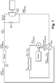
- Figure 1 illustrates a baseline recuperated "simple" thermodynamic cycle according to the background art wherein a working fluid, such as supercritical CO 2 , is pumped through a working fluid circuit in thermal communication with a waste heat exchanger WHX.
- a power turbine PT is fluidly coupled to the waste heat exchanger WHX downstream thereof.
- the working fluid is subsequently expanded in the power turbine PT in order to generate power or work.
- the power turbine PT may include any type of expansion device without departing from the scope of the disclosure.
- the working fluid is cooled at a recuperator RC1 and returned to a low temperature state at a condenser C.
- the working fluid is then directed to a pump P to commence the fluid circuit anew.
- the suction pressure at the pump P may be either subcritical or supercritical.
- a "mass management system" may also be included in each of the working fluid circuits disclosed to add or remove working fluid (i.e. , mass) from the system, and thereby make the system more efficient by increasing the overall system pressure ratio to the maximum possible extent while maintaining pump suction pressure at an acceptable level.
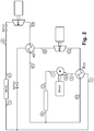
- Figure 2 schematically illustrates an exemplary embodiment of a "cascade" cycle in which the residual energy following the first-stage power turbine PT1 (i.e. , state 51) is used to preheat additional high pressure working fluid, or a downstream portion of the working fluid, to a temperature within approximately 5 to 10°C of the fluid at state 51.
- the downstream portion of the working fluid may subsequently be expanded through a second power turbine PT2 (or second stage turbine) adapted to drive a work-producing device.
- the work-producing device may be an electrical generator either coupled by a gearbox or directly driving a high-speed alternator. It is also possible to connect the output of PT2 with the work-producing device, or generator, being driven by PT1.
- first and second stage power turbines PT1, PT2 may be integrated into a single piece of turbomachinery, such as a multiple-stage turbine using separate blade/disks on a common shaft, or as separate stages of a radial turbine driving a bull gear using separate pinions for each radial turbine.
- the remainder of the cycle in Figure 2 may be substantially similar to the recuperated form of the cycle shown in Figure 1 , with the exception that the discharge from both recuperators RC1 and RC2 may be combined together to enter the condenser C. That is, exhaust from the second power turbine PT2 may pass through a second recuperator RC2 in order to reduce the temperature of the separated portion of the working fluid prior to being recombined with the remaining portion of working fluid preceding the condenser C.
- Pump P provides fluid pressure to flow the working fluid through the working fluid circuit of the cycle.
- Each of the recuperators RC1, RC2 and condensers C disclosed in Figure 2 , and those disclosed below in Figures 3-5 may, in at least one embodiment, include or employ one or more printed circuit heat exchange panels.
- Such heat exchangers and/or panels are known in the art, and are described in U.S. Pat. Nos. 6,921,518 ; 7,022,294 ; and 7,033,553 , the contents of which are incorporated by reference to the extent consistent with the present disclosure.
- the arrangement of the recuperators RC1, RC2 in any of the embodiments disclosed herein can be optimized in conjunction with the waste heat exchanger WHX to maximize power output of the multiple temperature expansion stages.
- balancing each side of the recuperators RC1, RC2 provides a higher overall cycle performance by improving the effectiveness of the recuperators RC1, RC2 for a given available heat exchange surface area.
- the waste heat exchanger(s) WHX used in the various embodiments disclosed herein may be any type of waste heat exchange device or medium operative to transfer thermal energy from a waste heat source or other heat source to the working fluid.
- the waste heat exchanger WHX may include a printed circuit heat exchanger.
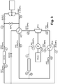
- Figure 3 is similar to Figure 2 , but with one key exception.
- the second power turbine PT2 may be coupled to the pump P either directly or through a gearbox.
- the motor that drives the pump P may still be used to provide power during system startup, and may provide a fraction of the drive load for the pump P under some conditions. In other cases, however, it is possible to utilize the motor as a generator, particularly if the second power turbine PT2 is able to produce more power than the pump P requires for system operation.
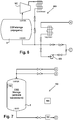
- Figure 4 is a variation of the system of Figure 3 , whereby the motor-driven pump P is replaced by or operatively connected to a high-speed, direct-drive turbopump TP.
- a small "starter pump” SP or other pumping device may be used during system startup, but once the turbopump TP generates sufficient power to "bootstrap" itself into steady-state operation, the starter pump SP can be shut down.
- Additional control valves CV1 and CV2 may be included to facilitate operation of the turbopump TP under varying load conditions. The additional control valves CV1, CV2 may also be used to get heat into the turbopump TP before the main power turbine PT has started.
- shut off valve SOV1 may be closed and the first control valve CV1 opened such that the heated working fluid discharged from the waste heat exchanger WHX may be directed to the turbopump TP in order to drive the system pump P until achieving steady-state operation.
- the control valve CV1 may be closed and simultaneously open the shut off valve SOV1 in order to direct heated working fluid from the waste heat exchanger WHX to the power turbine PT.
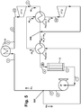
- Figure 5 schematically illustrates an exemplary embodiment of a dual cascade cycle which can be implemented in a heat engine cycle.
- the working fluid may be separated at point 502 into a first portion m 1 and a separated portion m 2 .
- the first portion m 1 may be directed to the waste heat exchanger WHX and subsequently expanded in the first stage power turbine PT1.
- Residual energy in the exhaust working fluid m 1 following the first stage power turbine PT1 (e.g ., state 5) may be used to preheat the separated portion m 2 in a second recuperator (Recup2) after the separated portion m 2 has previously passed through a first recuperator Recup1 to thereby increase its temperature.
- Recup2 second recuperator
- the second recuperator may be configured to preheat the separated portion m 2 to a temperature within approximately 5 to 10°C of the exhaust working fluid m 1 fluid at state 5.
- the separated portion m 2 at state 45 may be subsequently expanded through a second-stage power turbine PT2 and thereafter re-combine with the first portion m 1 at point 504.
- the re-combined working fluid m 1 + m 2 may then be directed to a loop including a first recuperator (Recup1), a condenser (e.g ., state 6), and a working fluid pump P ( e.g ., state 1).
- an optional bypass loop can be included whereby all or some of the working fluid can be directed through the bypass loop and not into one or more of the recuperators RC1, RC2.
- the working fluid circulated in each of the exemplary cycles described herein may be carbon dioxide.
- Carbon dioxide is a greenhouse friendly and neutral working fluid that offers benefits such as non-toxicity, non-flammability, easy availability, low price, and no need of recycling. It should be noted that the use of the term "carbon dioxide” is not intended to be limited to a carbon dioxide of any particular type, purity, or grade. For example, in at least one embodiment industrial grade carbon dioxide may be used.
- the working fluid circulated in each of the exemplary cycles described herein may a binary, ternary, or other working fluid blend.
- the working fluid combination can be selected for the unique attributes possessed by the fluid combination within a heat recovery system, as described herein.
- one such fluid combination includes a liquid absorbent and carbon dioxide mixture enabling the combined fluid to be pumped in a liquid state to high pressure with less energy input than required to compress CO 2 .
- the working fluid may be a combination of carbon dioxide or supercritical carbon dioxide and one or more other miscible fluids or chemical compounds.
- the working fluid may be a combination of carbon dioxide and propane, or carbon dioxide and ammonia, without departing from the scope of the disclosure.
- the working fluid may be in a supercritical state over certain portions of the system (the "high pressure side"), and in a subcritical state over other portions of the system (the “low pressure side”).
- the entire fluid cycle may be operated such that the working fluid is in a supercritical or subcritical state during the entire execution of the cycle.
- working fluid is not intended to limit the state or phase of matter that the working fluid is in.
- the working fluid may be in a fluid phase, a gas phase, a supercritical phase, a subcritical state, or any other phase or state at any one or more points within the fluid cycle.
- the pressure at the inlet of the pump P exceeds the vapor pressure of the working fluid by a margin sufficient to prevent vaporization of the fluid at the local regions of the low pressure and/or high velocity. This is especially important with high speed pumps such as the turbopumps used in the various embodiments disclosed herein. Consequently, a traditional passive system, such as one that employs a surge tank which only provides the incremental pressure of gravity relative to the fluid vapor pressure, is insufficient for the embodiments disclosed herein.
- carbon dioxide in power cycles requires particular attention to minimize the suction pressure of the pump P due to several factors.
- One factor is carbon dioxide's near-ambient critical temperature which requires the suction pressure of the pump P to be controlled both above and below the critical pressure (e.g ., subcritical and supercritical operation).
- Another factor to consider is carbon dioxide's relatively high compressibility which makes the volumetric and overall pump efficiency more sensitive to suction pressure margin than other working fluids.
- At least one more factor is carbon dioxide's low overall pressure ratio which makes the cycle efficiency more sensitive to suction pressure margin.
- embodiments of the disclosure further include the incorporation and use of a mass management system ("MMS") in connection with or integrated into the described thermodynamic fluid cycles.
- MMS mass management system
- the MMS may be configured to control the inlet pressure at the pump P by adding and/or removing mass from the system, and this in turn makes the system more efficient by increasing the overall system pressure ratio to the maximum possible extent.
- the MMS operates with the system semi-passively.
- the MMS may use sensors to monitor pressures and temperatures within the high pressure side (from pump P outlet to turbine PT1 inlet) and low pressure side (from turbine PT1 outlet to pump P inlet) of the system.
- the MMS may also include valves, tank heaters, pumps, or other equipment to facilitate the movement of the working fluid into and out of the system and a mass control tank for storage of working fluid.
- a waste heat recovery system that includes a MMS 100 having a plurality of valves 14, 15, 16, 17, 18, 21, 22, and 23, a mass control tank 7, and a control system 108.
- the MMS 100 is operatively connected to the waste heat recovery system at the valves or termination points 14, 15, 16, 17, 18, 21, 22, and 23.
- the MMS 100 is adapted to remove higher pressure and denser working fluid (relative to the pressure, temperature, and density on the low pressure side of the system) from the thermodynamic cycle via valve 16.
- the MMS 100 may dispense working fluid into the waste heat recovery system via valve 15.
- the MMS 100 automatically pressurizes the mass control tank 7 by opening valve 14 until the pressure within mass control tank 7 is sufficient to inject fluid through valve 15.
- the MMS 100 adds and/or removes mass (i.e. , working fluid) to/from the waste heat recovery system without the need of a pump, thereby reducing system cost, complexity, and maintenance.
- the MMS 100 includes a mass control tank 7 that may be filled with working fluid.
- the tank 7 may be in fluid communication with valves 14, 16 such that opening either or both valves 14, 16 will deliver working fluid to the top of the mass control tank 7.
- the mass control tank 7 may also be in fluid communication with the valve 15 such that opening the valve 15 will remove working fluid from the bottom of the mass control tank 7 to be injected into the waste heat recovery system adjacent and preceding the pump 9.
- the working fluid may be in liquid phase, vapor phase, or both, or in a supercritical state; if the working fluid is in both vapor phase and liquid phase, a phase boundary may separate the two phases whereby the denser working fluid settles at the bottom of the mass control tank 7.
- the working fluid contained within the mass control tank 7 will tend to stratify with the higher density working fluid at the bottom of the tank 7 and the lower density working fluid at the top of the tank 7. In this way, the valve 15 will be able to deliver to the waste heat recovery system the densest working fluid from within the mass control tank 7.
- a first set of sensors 102 may be arranged at the suction inlet of the pump 9 and be configured to measure and report the temperature, pressure, and mass flow rate of the working fluid at that point in the system.
- a second set of sensors 104 may be arranged at or adjacent the outlet of the pump 9 and configured to measure and report the temperature, pressure, and mass flow rate of the working fluid at that point in the system.
- a third set of sensors 106 may communicate with the mass control tank 7 and be configured to measure and report the pressure and temperature of the working fluid within the tank 7.
- Each set of sensors 102, 104, 106 may be in communication (wired and/or wireless) with a control system 108 that is also in communication with each of the valves 14, 15, 16 via actuators, servos, or other devices capable of manipulating the general disposition ( i.e. , open/closed) of each valve 14, 15, 16. Accordingly, the control system 108 may receive the measurement communications from each set of sensors 102, 104, 106 and adjust each valve 14, 15, 16 in order to maximize operation of the waste heat recovery system.
- the first set of sensors 102 may correspond to location 1 in Figures 1-5
- the second set of sensors 104 may correspond to location 2 in Figures 1-5 .
- the exemplary MMS 100 may also include points 18 and 19 used to purge and/or fill working fluid to/from the waste heat recovery system.
- Point 17 may be used to vent working fluid from the MMS 100, and other illustrated equipment is used in a variety of operating conditions such as start up, charging, and shut-down of the waste heat recovery system.
- a more detailed description of the other illustrated equipment may be found in copending U.S. patent application serial no. 12/631,379 entitled "Heat Engine and Heat to Electricity Systems and Methods," filed on December 4, 2009, the contents of which are hereby incorporated by reference to the extent consistent with the present disclosure.
- Operation of the exemplary MMS 100 follows.
- the working fluid such as CO 2
- the pressure in the mass control tank 7 must be increased to allow for the addition of mass into the waste heat recovery system.
- This can be controlled by opening valve 14 and thereby allowing higher pressure, higher temperature, lower density working fluid, such as supercritical CO 2 , to flow into the mass control tank 7.
- Valve 15 may be opened to allow higher density liquid working fluid at the bottom of the mass control tank 7 to flow into the waste heat recovery system and thereby increase the suction pressure of the pump 9.
- MMS 100 may be equally applicable as a supplement to the various thermodynamic cascade cycles disclosed herein, and shown generally in Figures 1-5 .
- Figure 7 schematically illustrates a mass management system 700 substantially similar to the MMS 100 shown in Figure 10
- Figure 6 schematically illustrates another exemplary mass management system 600.
- System tie-in points A, B, and C as shown in Figures 6, 7 and 10 correspond to the system tie-in points A, B, and C shown in Figures 1-5 .
- MMS 600 and 700 may each be fluidly coupled to the cascade cycled of Figures 1-5 at the corresponding system tie-in points A, B, and C (if applicable).
- the MMS 600 stores a working fluid at low (sub-ambient) temperature and therefore low pressure
- MMS 700 stores a working fluid at or near ambient temperature.
- the working fluid may be CO 2 , but may also be other working fluids without departing from the scope of the disclosure.
- a working fluid pump P is indicated in each of the described cascade cycles of Figures 1-5
- working fluid is supplied as necessary from a mass control tank T ( Figures 6 and 7 ) to an inlet of the pump P.
- the MMS 700 works by selectively adding working fluid to the main loop of the cascade cycle by pressurizing the working mass control tank T and then opening a valve at the bottom of the mass control tank T to flow into the rest of the cycle through interface or system tie-in C.
- the mass control tank T in Figure 7 may be pressurized by opening the valve at or adjacent interface A, and liquid may be released from the mass control tank T by opening the valve at or adjacent interface C. This process raises the system pump inlet pressure at pump P in Figures 1-5 .
- the valve at interface B ( Figure 7 ) may be opened, thereby permitting cool, pressurized fluid to enter the mass control tank T.
- the MMS 600 uses only two system tie-ins or interface points A and C.
- the valve-controlled interface A is not used during the control phase, and is provided only to pre-pressurize the main fluid loop with vapor so that the temperature of the main fluid loop remains above a minimum threshold during fill.
- working fluid is selectively added to the main system loop by pumping it in with a transfer pump 602 provided at or proximate interface C.
- the suction pressure of the pump P needs to be decreased, liquid is selectively extracted from the system at interface C and expanded through one or more valves down to the relatively low storage pressure. Under most conditions, the expanded fluid will be two-phase (i.e.
- vapor + liquid a small vapor compression refrigeration cycle (vapor compressor VC) is provided to decrease the fluid temperature and sufficiently condense the vapor to maintain the pressure of the mass control tank T at its design condition.
- the vapor compression refrigeration cycle may be integrated within the CO 2 storage tank system, or may be a standalone vapor compression cycle with an independent refrigerant loop.
- the MMS 700 may also include a transfer pump 704, substantially similar to the transfer pump 602 of Figure 6 .
- the transfer pump 704 may be configured to remove working fluid from the tank T and inject it into the working fluid circuit.
- control system 108 may include one or more proportional-integral-derivative (PID) controllers as control loop feedback systems.
- PID proportional-integral-derivative
- the control system 108 may be any microprocessor-based system capable of storing a control program and executing the control program to receive sensor inputs and generate control signals in accordance with a predetermined algorithm or table.
- the controller may be a microprocessor-based computer running a control software program stored on a compute readable medium.
- the software program may be configured to receive sensor inputs from various pressure, temperature, flow rate, etc. sensors positioned throughout the system and generate control signals therefrom, wherein the control signals are configured to optimize and/or selectively control the operation of the system.
- Each MMS 600, 700 may be communicably coupled to such a control system 108 such that control of the various valves and other equipment is automated or semi-automated and reacts to system performance data obtained via the various sensors located throughout the system, and also reacts to ambient and environmental conditions. That is to say that the controller 108 may be in communication with each of the components of the MMS 600, 700 and be configured to control the operation thereof to accomplish the function of the system more efficiently.
- the control system 108 may be in communication (via wires, RF signal, etc.) with each of the valves, pumps, sensors, etc. in the system and configured to control the operation of each of the components in accordance with a control software, algorithm, or other predetermined control mechanism.
- This may prove advantageous to control temperature and pressure of the working fluid at the inlet of the pump P, to actively increase the suction pressure of the pump P by decreasing compressibility of the working fluid. Doing so may avoid damage to the pump P as well as increase the overall pressure ratio of the cascade cycle, thereby improving the efficiency and power output.
- the suction pressure of the pump P may prove advantageous to maintain the suction pressure of the pump P above the boiling pressure of the working fluid at the inlet of the pump P.
- One method of controlling the pressure of the working fluid in the low side of the working fluid circuit is by controlling the temperature of the working fluid in the mass control tank T. This may be accomplished by maintaining the temperature of the mass control tank T at a higher level than the temperature at the inlet of the pump P.
- the MMS 600, 700 may include the use of a heater and/or a coil 702 within the tank T ( Figure 7 ).
- the heater/coil 702 may be configured to add or remove heat from the fluid/vapor within the tank T.
- the temperature of the mass control tank T may be controlled using direct electric heat.
- the temperature of the mass control tank T may be controlled using other devices, such as but not limited to, a heat exchanger coil with pump discharge fluid (which is at a higher temperature than at the pump inlet), a heat exchanger coil with spent cooling water from the cooler/condenser (also at a temperature higher than at the pump inlet), or combinations thereof.
- a heat exchanger coil with pump discharge fluid which is at a higher temperature than at the pump inlet
- a heat exchanger coil with spent cooling water from the cooler/condenser also at a temperature higher than at the pump inlet
- chilling systems 800 and 900 may also be employed in connection with any of the above-described cycles in order to provide cooling to other areas of an industrial process, including but not limited to pre-cooling of the inlet air of a gas-turbine or other air-breathing engines, thereby providing for a higher engine power output.
- System tie-in points B and D or C and D in Figures 8 and 9 may correspond to the system tie-in points B, C, and D in Figures 1-5 .
- chilling systems 800, 900 may each be fluidly coupled to the cascade cycles of Figures 1-5 at the corresponding system tie-in points B, C, and/or D (where applicable).
- a portion of the working fluid may be extracted from the working fluid circuit at system tie-in C.
- the pressure of that portion of fluid is reduced through an expansion device 902, which may be a valve, orifice, or fluid expander such as a turbine or positive displacement expander.
- This expansion process decreases the temperature of the working fluid.
- Heat is then added to the working fluid in an evaporator heat exchanger 904, which reduces the temperature of a process fluid (e.g ., air, as shown in Figures 8 and 9 ).
- the fluid pressure is then increased through the use of a compressor 802, where it is reintroduced to the working fluid circuit at system tie-in D.
- the compressor 802 shown in Figures 8 and 9 may be either motor-driven or turbine-driven off either a dedicated turbine or an additional wheel added to a primary turbine of the system. In other embodiments, the compressor 802 may be integrated with the main working fluid circuit. In other embodiments, the compressor 802 may take the form of a fluid ejector, with motive fluid supplied from system tie-in point A, and discharging to system tie-in point D, upstream from the condenser C. In the chilling system 800 of Figure 8 , the compressor 802 may take the form of a fluid ejector, with motive fluid supplied from system tie-in point A (not shown, but corresponding to point A in Figures 1-5 ), and discharging to system tie-in point D.
- the working fluid is extracted from system tie-in point B show in Figure 1-5 and pre-cooled by a heat exchanger 804 prior to expansion in an expansion device 806, similar to the expansion device 902 described above.
- the heat exchanger 804 may include a water, air, water-CO 2 , or air-CO 2 heat exchanger.
- the addition of the heat exchanger 804 may provide additional cooling capacity relative to the chilling system 900 shown in Figure 9 .
- Each of the described cascade cycles may be implemented in a variety of physical embodiments, including but not limited to fixed or integrated installations or as a self-contained device such as a portable waste heat engine or "skid” wherein the working fluid circuit and related components such as turbines, recuperators, condensers, pumps, valves, working fluid supply and control systems and mechanical and electronic controls are consolidated as a single unit, as further disclosed and described in the related applications.
- a portable waste heat engine or "skid” wherein the working fluid circuit and related components such as turbines, recuperators, condensers, pumps, valves, working fluid supply and control systems and mechanical and electronic controls are consolidated as a single unit, as further disclosed and described in the related applications.
- upstream and downstream as used herein are intended to more clearly describe various embodiments and configurations of the disclosure.
- upstream generally means toward or against the direction of flow of the working fluid during normal operation
- downstream generally means with or in the direction of the flow of the working fluid curing normal operation.
Landscapes
- Engineering & Computer Science (AREA)
- Chemical & Material Sciences (AREA)
- Combustion & Propulsion (AREA)
- Mechanical Engineering (AREA)
- General Engineering & Computer Science (AREA)
- Chemical Kinetics & Catalysis (AREA)
- Engine Equipment That Uses Special Cycles (AREA)
Description
- The present invention relates to a working fluid circuit for waste heat recovery and to a method of recovering waste heat in a working fluid circuit.
- Heat is often created as a byproduct of industrial processes where flowing streams of liquids, solids or gasses that contain heat must be exhausted into the environment or otherwise removed from the process an effort to maintain the operating temperatures of the industrial process equipment. Sometimes the industrial process can use heat exchanging devices to capture the heat and recycle it back into the process via other process streams. Other times it is not feasible to capture and recycle this heat because it is either too low in temperature or there is no readily available means to use as heat directly. This type of heat is generally referred to as "waste" heat, and is typically discharged directly into the environment through, for example, a stack, or indirectly through a cooling medium, such as water. In other settings, such heat is readily available from renewable sources of thermal energy, such as heat from the sun (which may be concentrated or otherwise manipulated) or geothermal sources. These and other thermal energy sources are intended to fall within the definition of "waste heat," as that term is used herein.
- Waste heat can be utilized by turbine generator systems that employ thermodynamic methods, such as the Rankine cycle, to convert heat into work. Typically, this method is steam-based, wherein the waste heat is used to raise steam in a boiler to drive a turbine. However, at least one of the key short-comings of a steam-based Rankine cycle is its high temperature requirement, which is not always practical since it generally requires a relatively high temperature (316°C (600°F) or higher) waste heat stream or a very large overall heat content. Also, the complexity of boiling water at multiple pressures/temperatures to capture heat at multiple temperature levels as the heat source stream is cooled is costly in both equipment cost and operating labor. Furthermore, the steam-based Rankine cycle is not a realistic option for streams of small flow rate and/or low temperature.
- The organic Rankine cycle (ORC) addresses the short-comings of steam-based Rankine cycles by replacing water with a lower boiling-point fluid, such as a light hydrocarbon like propane or butane, or a HCFC {e.g., R245fa) fluid. However, the boiling heat transfer restrictions remain, and new issues such as thermal instability, toxicity or flammability of the fluid are added.
- To address these short-comings, supercritical CO2 power cycles have been used. The supercritical state of the CO2 provides improved thermal coupling with multiple heat sources. For example, by using a supercritical fluid, the temperature glide of a process heat exchanger can be more readily matched. However, single cycle supercritical CO2 power cycles operate over a limited pressure ratio, thereby limiting the amount of temperature reduction, i.e., energy extraction, through the power conversion device (typically a turbine or positive displacement expander). The pressure ratio is limited primarily due to the high vapor pressure of the fluid at typically available condensation temperatures {e.g., ambient). As a result, the maximum output power that can be achieved from a single expansion stage is limited, and the expanded fluid retains a significant amount of potentially usable energy. While a portion of this residual energy can be recovered within the cycle by using a heat exchanger as a recuperator, and thus preheating the fluid between the pump and waste heat exchanger, this approach limits the amount of heat that can be extracted from the waste heat source in a single cycle.
- Accordingly, there exists a need in the art for a system that can efficiently and effectively produce power from not only waste heat, but also from a wide range of thermal sources.
- Document
US3971211 discloses a gas turbine, steam turbine and/or process steam systems combined with supercritical carbon dioxide cycle engines to produce major improvements in net plant efficiency by using the heat inputs and outputs of the supercritical CO2 cycle to supply or remove heat in advantageous ways to the gas turbine, steam turbine and/or process steam systems. - Document
WO2010/017981 discloses an operating fluid for a vapour circuit processing device having a vapour generator, an expander, a condenser and a reservoir for the operating fluid, comprising a working medium which vaporizes in the vapour generator as a result of heat being supplied, carries out mechanical work in the vapour phase through relaxation in the expander and condenses in the condenser, and an ionic fluid which mixes with the working medium, with the melting point of the mixture being below -5 °C. - The present disclosure is in the general field of thermodynamics and energy conversion, and more particularly applicable to conversion of thermal energy to work. The present disclosure improves the efficiency of a supercritical CO2 power cycle by "cascading" the residual energy back to a higher pressure fluid source, and expanding this fluid through an additional power conversion device. In addition, the unique characteristics of the CO2 cycle require active management of the main pump suction pressure and temperature relationship to provide optimal cycle efficiency. The present disclosure includes equipment and control strategies that enable superior performance to be achieved with the cascade CO2 cycle described herein.
- According to the present invention, there is provided a working fluid circuit for waste heat recovery having the features of
claim 1 below. - Optional features of the invention are set out in
dependent claims 2 to 7 below. - According to the present invention, there is provided a method of recovering waste heat in a working fluid circuit having the features of
claim 8 below. - Optional features of the method are set out in
dependent claims 9 to 12 below. - The present disclosure is best understood from the following detailed description when read with the accompanying Figures. It is emphasized that, in accordance with the standard practice in the industry, various features are not drawn to scale. In fact, the dimensions of the various features may be arbitrarily increased or reduced for clarity of discussion.
-
Figure 1 is a schematic of a simple thermodynamic waste heat recovery cycle according to the background art. -
Figure 2 is a schematic of an embodiment of a cascade thermodynamic waste heat recovery cycle, according to one or more embodiments disclosed. -
Figure 3 is a schematic of another cascade thermodynamic waste heat recovery cycle, according to one or more embodiments disclosed. -
Figure 4 is a schematic of another cascade thermodynamic waste heat recovery cycle, according to one or more embodiments disclosed. -
Figure 5 is a schematic of another cascade thermodynamic waste heat recovery cycle, according to one or more embodiments disclosed. -
Figure 6 is a schematic of a mass management system (MMS) which can be used in connection with the disclosed cascade thermodynamic waste heat recovery cycles, according to one or more embodiments disclosed. -
Figure 7 is a schematic of another mass management system (MMS) which can be used in connection with the disclosed cascade thermodynamic waste heat recovery cycles, according to one or more embodiments disclosed. -
Figures 8 and 9 schematically illustrate different system arrangements for inlet chilling of a separate fluid stream (e.g., air) by utilization of the working fluid which can be used in the exemplary heat engine cycles disclosed herein. -
Figure 10 illustrates an exemplary waste heat recovery system including a mass management system, according to one or more embodiments disclosed. - It is to be understood that the following disclosure describes several exemplary embodiments for implementing different features, structures, or functions of the invention. Exemplary embodiments of components, arrangements, and configurations are described below to simplify the present disclosure; however, these exemplary embodiments are provided merely as examples and are not intended to limit the scope of the invention which is solely defined by appended independent claims. Additionally, the present disclosure may repeat reference numerals and/or letters in the various exemplary embodiments and across the Figures provided herein. This repetition is for the purpose of simplicity and clarity and does not in itself dictate a relationship between the various exemplary embodiments and/or configurations discussed in the various Figures. Moreover, the formation of a first feature over or on a second feature in the description that follows may include embodiments in which the first and second features are formed in direct contact, and may also include embodiments in which additional features may be formed interposing the first and second features, such that the first and second features may not be in direct contact. Finally, the exemplary embodiments presented below may be combined in any combination of ways, i.e., any element from one exemplary embodiment may be used in any other exemplary embodiment, without departing from the scope of the invention, as long as the resulting embodiment contains at least all features of at least one of the independent claims.
- Additionally, certain terms are used throughout the following description and claims to refer to particular components. As one skilled in the art will appreciate, various entities may refer to the same component by different names, and as such, the naming convention for the elements described herein is not intended to limit the scope of the invention, unless otherwise specifically defined herein. Further, the naming convention used herein is not intended to distinguish between components that differ in name but not function. Additionally, in the following discussion and in the claims, the terms "including" and "comprising" are used in an open-ended fashion, and thus should be interpreted to mean "including, but not limited to." All numerical values in this disclosure may be exact or approximate values unless otherwise specifically stated. Furthermore, as it is used in the claims or specification, the term "or" is intended to encompass both exclusive and inclusive cases, i.e., "A or B" is intended to be synonymous with "at least one of A and B," unless otherwise expressly specified herein.
- The disclosure is made with reference to various embodiments as schematically depicted by the accompanying Figures. It should be noted that representative operative temperatures, pressures, and flow rates are indicated as examples only and are not in any way limiting to the scope of the disclosure.
-
Figure 1 illustrates a baseline recuperated "simple" thermodynamic cycle according to the background art wherein a working fluid, such as supercritical CO2, is pumped through a working fluid circuit in thermal communication with a waste heat exchanger WHX. A power turbine PT is fluidly coupled to the waste heat exchanger WHX downstream thereof. The working fluid is subsequently expanded in the power turbine PT in order to generate power or work. It will be appreciated, that the power turbine PT may include any type of expansion device without departing from the scope of the disclosure. The working fluid is cooled at a recuperator RC1 and returned to a low temperature state at a condenser C. The working fluid is then directed to a pump P to commence the fluid circuit anew. Depending upon the achievable temperature at the suction inlet of the pump P, and based on the available cooling supply temperature and condenser C performance, the suction pressure at the pump P may be either subcritical or supercritical. As will be described in more detail below, a "mass management system" may also be included in each of the working fluid circuits disclosed to add or remove working fluid (i.e., mass) from the system, and thereby make the system more efficient by increasing the overall system pressure ratio to the maximum possible extent while maintaining pump suction pressure at an acceptable level. - Subsequently, embodiments of the invention are described, wherein each embodiment of the invention comprises at least all features of at least one of the appended independent claims.
-
Figure 2 schematically illustrates an exemplary embodiment of a "cascade" cycle in which the residual energy following the first-stage power turbine PT1 (i.e., state 51) is used to preheat additional high pressure working fluid, or a downstream portion of the working fluid, to a temperature within approximately 5 to 10°C of the fluid atstate 51. The downstream portion of the working fluid may subsequently be expanded through a second power turbine PT2 (or second stage turbine) adapted to drive a work-producing device. In one embodiment, the work-producing device may be an electrical generator either coupled by a gearbox or directly driving a high-speed alternator. It is also possible to connect the output of PT2 with the work-producing device, or generator, being driven by PT1. In other embodiments, the first and second stage power turbines PT1, PT2 may be integrated into a single piece of turbomachinery, such as a multiple-stage turbine using separate blade/disks on a common shaft, or as separate stages of a radial turbine driving a bull gear using separate pinions for each radial turbine. - The remainder of the cycle in
Figure 2 may be substantially similar to the recuperated form of the cycle shown inFigure 1 , with the exception that the discharge from both recuperators RC1 and RC2 may be combined together to enter the condenser C. That is, exhaust from the second power turbine PT2 may pass through a second recuperator RC2 in order to reduce the temperature of the separated portion of the working fluid prior to being recombined with the remaining portion of working fluid preceding the condenser C. Pump P provides fluid pressure to flow the working fluid through the working fluid circuit of the cycle. - Each of the recuperators RC1, RC2 and condensers C disclosed in
Figure 2 , and those disclosed below inFigures 3-5 , may, in at least one embodiment, include or employ one or more printed circuit heat exchange panels. Such heat exchangers and/or panels are known in the art, and are described inU.S. Pat. Nos. 6,921,518 ;7,022,294 ; and7,033,553 , the contents of which are incorporated by reference to the extent consistent with the present disclosure. - By using multiple turbines PT1, PT2 at similar pressure ratios, a larger fraction of the available heat source from the waste heat exchanger WHX is utilized and residual heat from the turbines PT1, PT2 is recuperated. Consequently, additional heat is extracted from the waste heat source through multiple temperature expansions. As can be appreciated, using multiple turbines PT1, PT2 at similar pressure ratios utilizes a larger spectrum of the available heat source and the residual heat from each turbine PT1, PT2 can be recuperated and combined with any residual waste heat.
- In one or more embodiments, the arrangement of the recuperators RC1, RC2 in any of the embodiments disclosed herein can be optimized in conjunction with the waste heat exchanger WHX to maximize power output of the multiple temperature expansion stages. Also, both sides of each recuperator RC1, RC2 can be balanced, for example, by matching heat capacity rates and selectively merging the various flows in the working fluid circuits through waste heat exchangers and recuperators; C = m • cp, where C is the heat capacity rate, m is the mass flow rate of the working fluid, and cp is the constant pressure specific heat. As appreciated by those skilled in the art, balancing each side of the recuperators RC1, RC2 provides a higher overall cycle performance by improving the effectiveness of the recuperators RC1, RC2 for a given available heat exchange surface area.
- The waste heat exchanger(s) WHX used in the various embodiments disclosed herein may be any type of waste heat exchange device or medium operative to transfer thermal energy from a waste heat source or other heat source to the working fluid. In at least one embodiment, the waste heat exchanger WHX may include a printed circuit heat exchanger.
-
Figure 3 is similar toFigure 2 , but with one key exception. InFigure 3 , the second power turbine PT2 may be coupled to the pump P either directly or through a gearbox. The motor that drives the pump P may still be used to provide power during system startup, and may provide a fraction of the drive load for the pump P under some conditions. In other cases, however, it is possible to utilize the motor as a generator, particularly if the second power turbine PT2 is able to produce more power than the pump P requires for system operation. -
Figure 4 is a variation of the system ofFigure 3 , whereby the motor-driven pump P is replaced by or operatively connected to a high-speed, direct-drive turbopump TP. As illustrated, a small "starter pump" SP or other pumping device may be used during system startup, but once the turbopump TP generates sufficient power to "bootstrap" itself into steady-state operation, the starter pump SP can be shut down. Additional control valves CV1 and CV2 may be included to facilitate operation of the turbopump TP under varying load conditions. The additional control valves CV1, CV2 may also be used to get heat into the turbopump TP before the main power turbine PT has started. For example, at system startup the shut off valve SOV1 may be closed and the first control valve CV1 opened such that the heated working fluid discharged from the waste heat exchanger WHX may be directed to the turbopump TP in order to drive the system pump P until achieving steady-state operation. Once at steady-state operation, the control valve CV1 may be closed and simultaneously open the shut off valve SOV1 in order to direct heated working fluid from the waste heat exchanger WHX to the power turbine PT. -
Figure 5 schematically illustrates an exemplary embodiment of a dual cascade cycle which can be implemented in a heat engine cycle. Following the pump P, the working fluid may be separated atpoint 502 into a first portion m1 and a separated portion m2. The first portion m1 may be directed to the waste heat exchanger WHX and subsequently expanded in the first stage power turbine PT1. Residual energy in the exhaust working fluid m1 following the first stage power turbine PT1 (e.g., state 5) may be used to preheat the separated portion m2 in a second recuperator (Recup2) after the separated portion m2 has previously passed through a first recuperator Recup1 to thereby increase its temperature. In one embodiment, the second recuperator (Recup2) may be configured to preheat the separated portion m2 to a temperature within approximately 5 to 10°C of the exhaust working fluid m1 fluid atstate 5. The separated portion m2 atstate 45 may be subsequently expanded through a second-stage power turbine PT2 and thereafter re-combine with the first portion m1 atpoint 504. The re-combined working fluid m1 + m2 may then be directed to a loop including a first recuperator (Recup1), a condenser (e.g., state 6), and a working fluid pump P (e.g., state 1). - In all of the fluid circuit embodiments disclosed herein, and any equivalents thereof, an optional bypass loop can be included whereby all or some of the working fluid can be directed through the bypass loop and not into one or more of the recuperators RC1, RC2. By providing this flexibility to the system, the operator or control system can monitor and control operation according to the amount of heat available at one or more locations within the system, and thereby maximize efficiency.
- As briefly mentioned above, the working fluid circulated in each of the exemplary cycles described herein may be carbon dioxide. Carbon dioxide is a greenhouse friendly and neutral working fluid that offers benefits such as non-toxicity, non-flammability, easy availability, low price, and no need of recycling. It should be noted that the use of the term "carbon dioxide" is not intended to be limited to a carbon dioxide of any particular type, purity, or grade. For example, in at least one embodiment industrial grade carbon dioxide may be used.
- In other embodiments, the working fluid circulated in each of the exemplary cycles described herein may a binary, ternary, or other working fluid blend. The working fluid combination can be selected for the unique attributes possessed by the fluid combination within a heat recovery system, as described herein. For example, one such fluid combination includes a liquid absorbent and carbon dioxide mixture enabling the combined fluid to be pumped in a liquid state to high pressure with less energy input than required to compress CO2. In another embodiment, the working fluid may be a combination of carbon dioxide or supercritical carbon dioxide and one or more other miscible fluids or chemical compounds. In yet other embodiments, the working fluid may be a combination of carbon dioxide and propane, or carbon dioxide and ammonia, without departing from the scope of the disclosure.
- In the exemplary fluid cycles described herein, the working fluid may be in a supercritical state over certain portions of the system (the "high pressure side"), and in a subcritical state over other portions of the system (the "low pressure side"). In other embodiments, the entire fluid cycle may be operated such that the working fluid is in a supercritical or subcritical state during the entire execution of the cycle.
- Using the term "working fluid" is not intended to limit the state or phase of matter that the working fluid is in. In other words, the working fluid may be in a fluid phase, a gas phase, a supercritical phase, a subcritical state, or any other phase or state at any one or more points within the fluid cycle. For example, in one embodiment the pressure at the inlet of the pump P exceeds the vapor pressure of the working fluid by a margin sufficient to prevent vaporization of the fluid at the local regions of the low pressure and/or high velocity. This is especially important with high speed pumps such as the turbopumps used in the various embodiments disclosed herein. Consequently, a traditional passive system, such as one that employs a surge tank which only provides the incremental pressure of gravity relative to the fluid vapor pressure, is insufficient for the embodiments disclosed herein.
- The use of carbon dioxide in power cycles requires particular attention to minimize the suction pressure of the pump P due to several factors. One factor is carbon dioxide's near-ambient critical temperature which requires the suction pressure of the pump P to be controlled both above and below the critical pressure (e.g., subcritical and supercritical operation). Another factor to consider is carbon dioxide's relatively high compressibility which makes the volumetric and overall pump efficiency more sensitive to suction pressure margin than other working fluids. At least one more factor is carbon dioxide's low overall pressure ratio which makes the cycle efficiency more sensitive to suction pressure margin.
- In order to minimize the suction pressure of the pump P, among other benefits, embodiments of the disclosure further include the incorporation and use of a mass management system ("MMS") in connection with or integrated into the described thermodynamic fluid cycles. The MMS may be configured to control the inlet pressure at the pump P by adding and/or removing mass from the system, and this in turn makes the system more efficient by increasing the overall system pressure ratio to the maximum possible extent. In at least one embodiment, the MMS operates with the system semi-passively. For example, the MMS may use sensors to monitor pressures and temperatures within the high pressure side (from pump P outlet to turbine PT1 inlet) and low pressure side (from turbine PT1 outlet to pump P inlet) of the system. The MMS may also include valves, tank heaters, pumps, or other equipment to facilitate the movement of the working fluid into and out of the system and a mass control tank for storage of working fluid.
- Referring to
Figure 10 , illustrated is an exemplary embodiment of a waste heat recovery system that includes aMMS 100 having a plurality ofvalves control system 108. TheMMS 100 is operatively connected to the waste heat recovery system at the valves or termination points 14, 15, 16, 17, 18, 21, 22, and 23. In one embodiment, theMMS 100 is adapted to remove higher pressure and denser working fluid (relative to the pressure, temperature, and density on the low pressure side of the system) from the thermodynamic cycle viavalve 16. TheMMS 100 may dispense working fluid into the waste heat recovery system viavalve 15. TheMMS 100 automatically pressurizes the mass control tank 7 by openingvalve 14 until the pressure within mass control tank 7 is sufficient to inject fluid throughvalve 15. By controlling the operation of thevalves MMS 100 adds and/or removes mass (i.e., working fluid) to/from the waste heat recovery system without the need of a pump, thereby reducing system cost, complexity, and maintenance. - In the illustrated embodiment, the
MMS 100 includes a mass control tank 7 that may be filled with working fluid. The tank 7 may be in fluid communication withvalves valves valve 15 such that opening thevalve 15 will remove working fluid from the bottom of the mass control tank 7 to be injected into the waste heat recovery system adjacent and preceding thepump 9. Within the mass control tank 7 the working fluid may be in liquid phase, vapor phase, or both, or in a supercritical state; if the working fluid is in both vapor phase and liquid phase, a phase boundary may separate the two phases whereby the denser working fluid settles at the bottom of the mass control tank 7. Consequently, the working fluid contained within the mass control tank 7 will tend to stratify with the higher density working fluid at the bottom of the tank 7 and the lower density working fluid at the top of the tank 7. In this way, thevalve 15 will be able to deliver to the waste heat recovery system the densest working fluid from within the mass control tank 7. - A first set of
sensors 102 may be arranged at the suction inlet of thepump 9 and be configured to measure and report the temperature, pressure, and mass flow rate of the working fluid at that point in the system. A second set ofsensors 104 may be arranged at or adjacent the outlet of thepump 9 and configured to measure and report the temperature, pressure, and mass flow rate of the working fluid at that point in the system. A third set ofsensors 106 may communicate with the mass control tank 7 and be configured to measure and report the pressure and temperature of the working fluid within the tank 7. Each set ofsensors control system 108 that is also in communication with each of thevalves valve control system 108 may receive the measurement communications from each set ofsensors valve sensors 102 may correspond tolocation 1 inFigures 1-5 , and the second set ofsensors 104 may correspond tolocation 2 inFigures 1-5 . - The
exemplary MMS 100 may also includepoints 18 and 19 used to purge and/or fill working fluid to/from the waste heat recovery system.Point 17 may be used to vent working fluid from theMMS 100, and other illustrated equipment is used in a variety of operating conditions such as start up, charging, and shut-down of the waste heat recovery system. A more detailed description of the other illustrated equipment may be found in copendingU.S. patent application serial no. 12/631,379 - Operation of the
exemplary MMS 100 follows. When the working fluid, such as CO2, in the mass storage tank 7 is at the fluid vapor pressure for a given ambient temperature, and the low side pressure in the waste heat recovery system is above the vapor pressure, the pressure in the mass control tank 7 must be increased to allow for the addition of mass into the waste heat recovery system. This can be controlled by openingvalve 14 and thereby allowing higher pressure, higher temperature, lower density working fluid, such as supercritical CO2, to flow into the mass control tank 7.Valve 15 may be opened to allow higher density liquid working fluid at the bottom of the mass control tank 7 to flow into the waste heat recovery system and thereby increase the suction pressure of thepump 9. - The description of the foregoing
MMS 100 may be equally applicable as a supplement to the various thermodynamic cascade cycles disclosed herein, and shown generally inFigures 1-5 . For example, referring now toFigures 6 and 7, Figure 7 schematically illustrates amass management system 700 substantially similar to theMMS 100 shown inFigure 10 , andFigure 6 schematically illustrates another exemplarymass management system 600. System tie-in points A, B, and C as shown inFigures 6, 7 and10 (only points A and C shown inFigure 6 ) correspond to the system tie-in points A, B, and C shown inFigures 1-5 . Accordingly,MMS Figures 1-5 at the corresponding system tie-in points A, B, and C (if applicable). TheMMS 600 stores a working fluid at low (sub-ambient) temperature and therefore low pressure, andMMS 700 stores a working fluid at or near ambient temperature. As discussed above, the working fluid may be CO2, but may also be other working fluids without departing from the scope of the disclosure. - Where a working fluid pump P is indicated in each of the described cascade cycles of
Figures 1-5 , working fluid is supplied as necessary from a mass control tank T (Figures 6 and 7 ) to an inlet of the pump P. In operation, theMMS 700 works by selectively adding working fluid to the main loop of the cascade cycle by pressurizing the working mass control tank T and then opening a valve at the bottom of the mass control tank T to flow into the rest of the cycle through interface or system tie-in C. For example, the mass control tank T inFigure 7 may be pressurized by opening the valve at or adjacent interface A, and liquid may be released from the mass control tank T by opening the valve at or adjacent interface C. This process raises the system pump inlet pressure at pump P inFigures 1-5 . To extract fluid from the main system loop, and decrease the system pump inlet pressure, the valve at interface B (Figure 7 ) may be opened, thereby permitting cool, pressurized fluid to enter the mass control tank T. - In the embodiment of
Figure 6 , theMMS 600 uses only two system tie-ins or interface points A and C. The valve-controlled interface A is not used during the control phase, and is provided only to pre-pressurize the main fluid loop with vapor so that the temperature of the main fluid loop remains above a minimum threshold during fill. In operation, when the suction pressure of the pump P shown inFigures 1-5 needs to be increased, working fluid is selectively added to the main system loop by pumping it in with atransfer pump 602 provided at or proximate interface C. When the suction pressure of the pump P needs to be decreased, liquid is selectively extracted from the system at interface C and expanded through one or more valves down to the relatively low storage pressure. Under most conditions, the expanded fluid will be two-phase (i.e., vapor + liquid). To prevent the pressure in the mass control tank T from exceeding its normal operating limits, a small vapor compression refrigeration cycle (vapor compressor VC) is provided to decrease the fluid temperature and sufficiently condense the vapor to maintain the pressure of the mass control tank T at its design condition. The vapor compression refrigeration cycle may be integrated within the CO2 storage tank system, or may be a standalone vapor compression cycle with an independent refrigerant loop. - Although not necessary in every application, the
MMS 700 may also include atransfer pump 704, substantially similar to thetransfer pump 602 ofFigure 6 . Thetransfer pump 704 may be configured to remove working fluid from the tank T and inject it into the working fluid circuit. - All of the various described controls or changes to the working fluid environment and status throughout the cascade cycle, including temperature, pressure, flow direction and rate, and component operation such as pumps and turbines, may be monitored and/or controlled by a
control system 108, as generally described above with reference toFigures 6, 7 , and10 . In one embodiment, thecontrol system 108 may include one or more proportional-integral-derivative (PID) controllers as control loop feedback systems. In another embodiment, thecontrol system 108 may be any microprocessor-based system capable of storing a control program and executing the control program to receive sensor inputs and generate control signals in accordance with a predetermined algorithm or table. For example, the controller may be a microprocessor-based computer running a control software program stored on a compute readable medium. The software program may be configured to receive sensor inputs from various pressure, temperature, flow rate, etc. sensors positioned throughout the system and generate control signals therefrom, wherein the control signals are configured to optimize and/or selectively control the operation of the system. - Each
MMS control system 108 such that control of the various valves and other equipment is automated or semi-automated and reacts to system performance data obtained via the various sensors located throughout the system, and also reacts to ambient and environmental conditions. That is to say that thecontroller 108 may be in communication with each of the components of theMMS control system 108 may be in communication (via wires, RF signal, etc.) with each of the valves, pumps, sensors, etc. in the system and configured to control the operation of each of the components in accordance with a control software, algorithm, or other predetermined control mechanism. This may prove advantageous to control temperature and pressure of the working fluid at the inlet of the pump P, to actively increase the suction pressure of the pump P by decreasing compressibility of the working fluid. Doing so may avoid damage to the pump P as well as increase the overall pressure ratio of the cascade cycle, thereby improving the efficiency and power output. - In one or more embodiments, it may prove advantageous to maintain the suction pressure of the pump P above the boiling pressure of the working fluid at the inlet of the pump P. One method of controlling the pressure of the working fluid in the low side of the working fluid circuit is by controlling the temperature of the working fluid in the mass control tank T. This may be accomplished by maintaining the temperature of the mass control tank T at a higher level than the temperature at the inlet of the pump P. To accomplish this, the
MMS coil 702 within the tank T (Figure 7 ). The heater/coil 702 may be configured to add or remove heat from the fluid/vapor within the tank T. In one embodiment, the temperature of the mass control tank T may be controlled using direct electric heat. In other embodiments, however, the temperature of the mass control tank T may be controlled using other devices, such as but not limited to, a heat exchanger coil with pump discharge fluid (which is at a higher temperature than at the pump inlet), a heat exchanger coil with spent cooling water from the cooler/condenser (also at a temperature higher than at the pump inlet), or combinations thereof. - Referring now to
Figures 8 and 9 ,chilling systems Figures 8 and 9 may correspond to the system tie-in points B, C, and D inFigures 1-5 . Accordingly,chilling systems Figures 1-5 at the corresponding system tie-in points B, C, and/or D (where applicable). In thechilling system 900 ofFigure 9 , a portion of the working fluid may be extracted from the working fluid circuit at system tie-in C. The pressure of that portion of fluid is reduced through anexpansion device 902, which may be a valve, orifice, or fluid expander such as a turbine or positive displacement expander. This expansion process decreases the temperature of the working fluid. Heat is then added to the working fluid in anevaporator heat exchanger 904, which reduces the temperature of a process fluid (e.g., air, as shown inFigures 8 and 9 ). The fluid pressure is then increased through the use of acompressor 802, where it is reintroduced to the working fluid circuit at system tie-in D. - The
compressor 802 shown inFigures 8 and 9 may be either motor-driven or turbine-driven off either a dedicated turbine or an additional wheel added to a primary turbine of the system. In other embodiments, thecompressor 802 may be integrated with the main working fluid circuit. In other embodiments, thecompressor 802 may take the form of a fluid ejector, with motive fluid supplied from system tie-in point A, and discharging to system tie-in point D, upstream from the condenser C. In thechilling system 800 ofFigure 8 , thecompressor 802 may take the form of a fluid ejector, with motive fluid supplied from system tie-in point A (not shown, but corresponding to point A inFigures 1-5 ), and discharging to system tie-in point D. In another embodiment, the working fluid is extracted from system tie-in point B show inFigure 1-5 and pre-cooled by aheat exchanger 804 prior to expansion in anexpansion device 806, similar to theexpansion device 902 described above. In one embodiment, theheat exchanger 804 may include a water, air, water-CO2, or air-CO2 heat exchanger. As can be appreciated, the addition of theheat exchanger 804 may provide additional cooling capacity relative to thechilling system 900 shown inFigure 9 . - Each of the described cascade cycles may be implemented in a variety of physical embodiments, including but not limited to fixed or integrated installations or as a self-contained device such as a portable waste heat engine or "skid" wherein the working fluid circuit and related components such as turbines, recuperators, condensers, pumps, valves, working fluid supply and control systems and mechanical and electronic controls are consolidated as a single unit, as further disclosed and described in the related applications.
- The terms "upstream" and "downstream" as used herein are intended to more clearly describe various embodiments and configurations of the disclosure. For example, "upstream" generally means toward or against the direction of flow of the working fluid during normal operation, and "downstream" generally means with or in the direction of the flow of the working fluid curing normal operation.
- The foregoing has outlined features of several embodiments so that those skilled in the art may better understand the present disclosure. Those skilled in the art should appreciate that they may readily use the present disclosure as a basis for designing or modifying other processes and structures for carrying out the same purposes and/or achieving the same advantages of the embodiments introduced herein. The present invention is defined by appended claims.
Claims (12)
- A working fluid circuit for waste heat recovery, comprising:a pump (P) operative to direct a working fluid within the working fluid circuit to a waste heat exchanger (WHX) fluidly coupled to the pump;a first expansion device (PT1) fluidly coupled to the waste heat exchanger and configured to receive the working fluid from the waste heat exchanger;a first recuperator (RC1) fluidly coupled to the first expansion device and configured to receive the working fluid from the first expansion device and transfer heat from the working fluid to a downstream portion of the working fluid;a second expansion device (PT2) fluidly coupled to the pump downstream from the pump and configured to receive the downstream portion of the working fluid;a second recuperator (RC2) fluidly coupled to the second expansion device and configured to receive the downstream portion of the working fluid from the second expansion device;a condenser (C) fluidly coupled to the first recuperator and the second recuperator, wherein the working fluid discharge from both the first recuperator and the second recuperator are combined prior to entering the condenser; anda mass management system (100) having a first system tie-in (A) fluidly coupled upstream from the first expansion device and a second system tie-in (C) fluidly coupled upstream from the pump, the mass management system having a mass control tank (7) configured to selectively receive the working fluid from the working fluid circuit via the first system tie-in and to selectively input the working fluid into the working fluid circuit via the second system tie-in.
- The working fluid circuit of claim 1, wherein the second expansion device (PT2) is configured to drive the pump (P).
- The working fluid circuit of claim 2, further comprising a starter pump (SP) fluidly coupled to a downstream side of the condenser (C) and a downstream side of the pump (P).
- The working fluid circuit of claim 1, wherein the working fluid comprises carbon dioxide.
- The working fluid circuit of claim 4, wherein the working fluid is in a supercritical state through a portion of the working fluid circuit.
- The working fluid circuit of claim 1, wherein the first and second expansion devices (PT1, PT2) are power turbines.
- The working fluid circuit of claim 1, wherein the mass management system (100) comprises a system controller (108) configured to sense at least one of a temperature and a pressure in the working fluid circuit, and in response thereto, generate control signals for at least one of a plurality of selectively-actuated valves (14, 15, 16) and/or pumps (9) arranged in the working fluid circuit, the mass management system being configured to maintain a pressure at an inlet of the pump between a low pressure level greater than a saturation pressure of the working fluid and a high pressure level greater than the low pressure level.
- A method of recovering waste heat in a working fluid circuit, comprising:pumping a working fluid within the working fluid circuit by a pump (P), the working fluid being separated into a first portion and a separated portion downstream from the pump, wherein the first portion of the working fluid within the working fluid circuit is pumped to a waste heat exchanger (WHX) fluidly coupled to the pump and the separated portion of the working fluid is pumped through a first recuperator (RC1);transferring thermal energy from the first recuperator to the separated portion of the working fluid;expanding the first portion of the working fluid in a first expansion device (PT1) fluidly coupled to the waste heat exchanger;transferring thermal energy from the first portion of the working fluid to the separated portion of the working fluid in a second recuperator (RC2) fluidly coupled to the first expansion device, the second recuperator being configured to receive the separated portion of the working fluid following the first recuperator;expanding the separated portion of the working fluid in a second expansion device (PT2) configured to receive the separated portion from the second recuperator;re-combining the first portion and the separated portion of the working fluid to pass through the first recuperator and a condenser (C), the condenser being fluidly coupled to the first recuperator; andcontrolling an amount of working fluid mass in the working fluid circuit with a mass management system (100) having a mass control tank (7) fluidly coupled to a first system tie-in (B) and a second system tie-in (C), the first system tie-in being fluidly coupled upstream from the first expansion device and the second system tie-in being fluidly coupled upstream from the pump.
- The method of claim 8, further comprising:receiving the working fluid from the working fluid circuit into the mass control tank (7) via the first system tie-in (B); andinputting the working fluid into the working fluid circuit via the second system tie-in (C).
- The method of claim 9, further comprising controlling with a control system (108) a flow of working fluid to the working fluid circuit and to the pump (P), the control system being configured to maintain a pressure at an inlet of the pump between a low pressure level greater than a saturation pressure of the working fluid and a high pressure level greater than the low pressure level.
- The method of claim 8, wherein the working fluid comprises carbon dioxide.
- The method of claim 11, wherein the working fluid is in a supercritical state through a portion of the working fluid circuit.
Applications Claiming Priority (3)
| Application Number | Priority Date | Filing Date | Title |
|---|---|---|---|
| US31650710P | 2010-03-23 | 2010-03-23 | |
| US41777510P | 2010-11-29 | 2010-11-29 | |
| PCT/US2011/029486 WO2011119650A2 (en) | 2010-03-23 | 2011-03-22 | Heat engines with cascade cycles |
Publications (3)
| Publication Number | Publication Date |
|---|---|
| EP2550436A2 EP2550436A2 (en) | 2013-01-30 |
| EP2550436A4 EP2550436A4 (en) | 2016-04-20 |
| EP2550436B1 true EP2550436B1 (en) | 2019-08-07 |
Family
ID=44673843
Family Applications (1)
| Application Number | Title | Priority Date | Filing Date |
|---|---|---|---|
| EP11760095.7A Active EP2550436B1 (en) | 2010-03-23 | 2011-03-22 | Heat engines with cascade cycles |
Country Status (4)
| Country | Link |
|---|---|
| EP (1) | EP2550436B1 (en) |
| BR (1) | BR112012024146B1 (en) |
| CA (1) | CA2794150C (en) |
| WO (1) | WO2011119650A2 (en) |
Cited By (12)
| Publication number | Priority date | Publication date | Assignee | Title |
|---|---|---|---|---|
| US11480074B1 (en) | 2021-04-02 | 2022-10-25 | Ice Thermal Harvesting, Llc | Systems and methods utilizing gas temperature as a power source |
| US11486330B2 (en) | 2021-04-02 | 2022-11-01 | Ice Thermal Harvesting, Llc | Systems and methods utilizing gas temperature as a power source |
| US11486370B2 (en) | 2021-04-02 | 2022-11-01 | Ice Thermal Harvesting, Llc | Modular mobile heat generation unit for generation of geothermal power in organic Rankine cycle operations |
| US11493029B2 (en) | 2021-04-02 | 2022-11-08 | Ice Thermal Harvesting, Llc | Systems and methods for generation of electrical power at a drilling rig |
| US11578706B2 (en) | 2021-04-02 | 2023-02-14 | Ice Thermal Harvesting, Llc | Systems for generating geothermal power in an organic Rankine cycle operation during hydrocarbon production based on wellhead fluid temperature |
| US11592009B2 (en) | 2021-04-02 | 2023-02-28 | Ice Thermal Harvesting, Llc | Systems and methods for generation of electrical power at a drilling rig |
| US11644015B2 (en) | 2021-04-02 | 2023-05-09 | Ice Thermal Harvesting, Llc | Systems and methods for generation of electrical power at a drilling rig |
| US11644014B2 (en) | 2021-04-02 | 2023-05-09 | Ice Thermal Harvesting, Llc | Systems and methods for generation of electrical power in an organic Rankine cycle operation |
| US11959466B2 (en) | 2021-04-02 | 2024-04-16 | Ice Thermal Harvesting, Llc | Systems and methods for generation of electrical power in an organic Rankine cycle operation |
| US12180861B1 (en) | 2022-12-30 | 2024-12-31 | Ice Thermal Harvesting, Llc | Systems and methods to utilize heat carriers in conversion of thermal energy |
| US12312981B2 (en) | 2021-04-02 | 2025-05-27 | Ice Thermal Harvesting, Llc | Systems and methods utilizing gas temperature as a power source |
| US12534990B2 (en) | 2022-12-29 | 2026-01-27 | Ice Thermal Harvesting, Llc | Power generation assemblies for hydraulic fracturing systems and methods |
Families Citing this family (45)
| Publication number | Priority date | Publication date | Assignee | Title |
|---|---|---|---|---|
| US9014791B2 (en) | 2009-04-17 | 2015-04-21 | Echogen Power Systems, Llc | System and method for managing thermal issues in gas turbine engines |
| CN102575532B (en) | 2009-06-22 | 2015-03-18 | 艾克竣电力系统股份有限公司 | Systems and methods for temperature regulation of inlet gas |
| WO2011017476A1 (en) | 2009-08-04 | 2011-02-10 | Echogen Power Systems Inc. | Heat pump with integral solar collector |
| US8794002B2 (en) | 2009-09-17 | 2014-08-05 | Echogen Power Systems | Thermal energy conversion method |
| US8813497B2 (en) | 2009-09-17 | 2014-08-26 | Echogen Power Systems, Llc | Automated mass management control |
| US8613195B2 (en) | 2009-09-17 | 2013-12-24 | Echogen Power Systems, Llc | Heat engine and heat to electricity systems and methods with working fluid mass management control |
| US8869531B2 (en) | 2009-09-17 | 2014-10-28 | Echogen Power Systems, Llc | Heat engines with cascade cycles |
| US10094219B2 (en) | 2010-03-04 | 2018-10-09 | X Development Llc | Adiabatic salt energy storage |
| US8857186B2 (en) | 2010-11-29 | 2014-10-14 | Echogen Power Systems, L.L.C. | Heat engine cycles for high ambient conditions |
| US8783034B2 (en) | 2011-11-07 | 2014-07-22 | Echogen Power Systems, Llc | Hot day cycle |
| US8616001B2 (en) * | 2010-11-29 | 2013-12-31 | Echogen Power Systems, Llc | Driven starter pump and start sequence |
| WO2013055391A1 (en) * | 2011-10-03 | 2013-04-18 | Echogen Power Systems, Llc | Carbon dioxide refrigeration cycle |
| ITCO20110063A1 (en) * | 2011-12-14 | 2013-06-15 | Nuovo Pignone Spa | CLOSED CYCLE SYSTEM TO RECOVER HIDDEN HEAT |
| CA2882290A1 (en) | 2012-08-20 | 2014-02-27 | Echogen Power Systems, L.L.C. | Supercritical working fluid circuit with a turbo pump and a start pump in series configuration |
| WO2014052927A1 (en) | 2012-09-27 | 2014-04-03 | Gigawatt Day Storage Systems, Inc. | Systems and methods for energy storage and retrieval |
| US9341084B2 (en) | 2012-10-12 | 2016-05-17 | Echogen Power Systems, Llc | Supercritical carbon dioxide power cycle for waste heat recovery |
| US9118226B2 (en) | 2012-10-12 | 2015-08-25 | Echogen Power Systems, Llc | Heat engine system with a supercritical working fluid and processes thereof |
| US20140102098A1 (en) | 2012-10-12 | 2014-04-17 | Echogen Power Systems, Llc | Bypass and throttle valves for a supercritical working fluid circuit |
| WO2014117068A1 (en) * | 2013-01-28 | 2014-07-31 | Echogen Power Systems, L.L.C. | Methods for reducing wear on components of a heat engine system at startup |
| US9752460B2 (en) | 2013-01-28 | 2017-09-05 | Echogen Power Systems, Llc | Process for controlling a power turbine throttle valve during a supercritical carbon dioxide rankine cycle |
| CA2903784C (en) | 2013-03-04 | 2021-03-16 | Echogen Power Systems, L.L.C. | Heat engine systems with high net power supercritical carbon dioxide circuits |
| US10030546B2 (en) | 2013-09-25 | 2018-07-24 | Siemens Aktiengesellschaft | Arrangement and method utilizing waste heat |
| WO2015047120A1 (en) | 2013-09-25 | 2015-04-02 | Siemens Aktiengesellschaft | Arrangement and method for the utilization of waste heat |
| EP3167166B1 (en) | 2014-09-08 | 2020-11-04 | Siemens Aktiengesellschaft | System and method for recovering waste heat energy |
| WO2016073252A1 (en) | 2014-11-03 | 2016-05-12 | Echogen Power Systems, L.L.C. | Active thrust management of a turbopump within a supercritical working fluid circuit in a heat engine system |
| US10458284B2 (en) | 2016-12-28 | 2019-10-29 | Malta Inc. | Variable pressure inventory control of closed cycle system with a high pressure tank and an intermediate pressure tank |
| US10233833B2 (en) | 2016-12-28 | 2019-03-19 | Malta Inc. | Pump control of closed cycle power generation system |
| US11053847B2 (en) | 2016-12-28 | 2021-07-06 | Malta Inc. | Baffled thermoclines in thermodynamic cycle systems |
| US10221775B2 (en) | 2016-12-29 | 2019-03-05 | Malta Inc. | Use of external air for closed cycle inventory control |
| US10436109B2 (en) | 2016-12-31 | 2019-10-08 | Malta Inc. | Modular thermal storage |
| CN111699302A (en) * | 2017-12-18 | 2020-09-22 | 艾赛杰国际有限公司 | Method, apparatus and thermodynamic cycle for generating power from a variable temperature heat source |
| US10883388B2 (en) | 2018-06-27 | 2021-01-05 | Echogen Power Systems Llc | Systems and methods for generating electricity via a pumped thermal energy storage system |
| CN116624238A (en) | 2019-11-16 | 2023-08-22 | 马耳他股份有限公司 | Dual power system pumping thermoelectric storage mode conversion |
| US11435120B2 (en) | 2020-05-05 | 2022-09-06 | Echogen Power Systems (Delaware), Inc. | Split expansion heat pump cycle |
| US11480067B2 (en) | 2020-08-12 | 2022-10-25 | Malta Inc. | Pumped heat energy storage system with generation cycle thermal integration |
| US11286804B2 (en) | 2020-08-12 | 2022-03-29 | Malta Inc. | Pumped heat energy storage system with charge cycle thermal integration |
| US11486305B2 (en) | 2020-08-12 | 2022-11-01 | Malta Inc. | Pumped heat energy storage system with load following |
| US11396826B2 (en) | 2020-08-12 | 2022-07-26 | Malta Inc. | Pumped heat energy storage system with electric heating integration |
| EP4193041A1 (en) | 2020-08-12 | 2023-06-14 | Malta Inc. | Pumped heat energy storage system with district heating integration |
| EP4193039A1 (en) | 2020-08-12 | 2023-06-14 | Malta Inc. | Pumped heat energy storage system with modular turbomachinery |
| US11454167B1 (en) | 2020-08-12 | 2022-09-27 | Malta Inc. | Pumped heat energy storage system with hot-side thermal integration |
| AU2021397292A1 (en) | 2020-12-09 | 2023-07-06 | Supercritical Storage Company, Inc. | Three reservoir electric thermal energy storage system |
| US12428979B2 (en) | 2021-12-14 | 2025-09-30 | Malta Inc. | Pumped heat energy storage system integrated with coal-fired energy generation unit |
| US12516855B2 (en) | 2022-10-27 | 2026-01-06 | Supercritical Storage Company, Inc. | High-temperature, dual rail heat pump cycle for high performance at high-temperature lift and range |
| US12331664B2 (en) | 2023-02-07 | 2025-06-17 | Supercritical Storage Company, Inc. | Waste heat integration into pumped thermal energy storage |
Family Cites Families (8)
| Publication number | Priority date | Publication date | Assignee | Title |
|---|---|---|---|---|
| US3971211A (en) | 1974-04-02 | 1976-07-27 | Mcdonnell Douglas Corporation | Thermodynamic cycles with supercritical CO2 cycle topping |
| ES2005135A6 (en) * | 1987-04-08 | 1989-03-01 | Carnot Sa | Power cycle working with a mixture of substances. |
| US4995234A (en) * | 1989-10-02 | 1991-02-26 | Chicago Bridge & Iron Technical Services Company | Power generation from LNG |
| JPH09209716A (en) * | 1996-02-07 | 1997-08-12 | Toshiba Corp | Power plant |
| JP2005533972A (en) * | 2002-07-22 | 2005-11-10 | スティンガー、ダニエル・エイチ | Cascading closed-loop cycle power generation |
| JP4027295B2 (en) * | 2003-10-02 | 2007-12-26 | 本田技研工業株式会社 | Liquid level position control device for condenser in Rankine cycle system |
| US20100263380A1 (en) * | 2007-10-04 | 2010-10-21 | United Technologies Corporation | Cascaded organic rankine cycle (orc) system using waste heat from a reciprocating engine |
| DE102008037744A1 (en) | 2008-08-14 | 2010-02-25 | Voith Patent Gmbh | Operating fluid for a steam cycle device and a method of operation thereof |
-
2011
- 2011-03-22 WO PCT/US2011/029486 patent/WO2011119650A2/en not_active Ceased
- 2011-03-22 CA CA2794150A patent/CA2794150C/en active Active
- 2011-03-22 EP EP11760095.7A patent/EP2550436B1/en active Active
- 2011-03-22 BR BR112012024146-0A patent/BR112012024146B1/en active IP Right Grant
Non-Patent Citations (1)
| Title |
|---|
| None * |
Cited By (40)
| Publication number | Priority date | Publication date | Assignee | Title |
|---|---|---|---|---|
| US11905934B2 (en) | 2021-04-02 | 2024-02-20 | Ice Thermal Harvesting, Llc | Systems and methods for generation of electrical power at a drilling rig |
| US11680541B2 (en) | 2021-04-02 | 2023-06-20 | Ice Thermal Harvesting, Llc | Systems and methods utilizing gas temperature as a power source |
| US11486370B2 (en) | 2021-04-02 | 2022-11-01 | Ice Thermal Harvesting, Llc | Modular mobile heat generation unit for generation of geothermal power in organic Rankine cycle operations |
| US11493029B2 (en) | 2021-04-02 | 2022-11-08 | Ice Thermal Harvesting, Llc | Systems and methods for generation of electrical power at a drilling rig |
| US11542888B2 (en) | 2021-04-02 | 2023-01-03 | Ice Thermal Harvesting, Llc | Systems and methods utilizing gas temperature as a power source |
| US11549402B2 (en) | 2021-04-02 | 2023-01-10 | Ice Thermal Harvesting, Llc | Systems and methods utilizing gas temperature as a power source |
| US11572849B1 (en) | 2021-04-02 | 2023-02-07 | Ice Thermal Harvesting, Llc | Systems and methods utilizing gas temperature as a power source |
| US11578706B2 (en) | 2021-04-02 | 2023-02-14 | Ice Thermal Harvesting, Llc | Systems for generating geothermal power in an organic Rankine cycle operation during hydrocarbon production based on wellhead fluid temperature |
| US11592009B2 (en) | 2021-04-02 | 2023-02-28 | Ice Thermal Harvesting, Llc | Systems and methods for generation of electrical power at a drilling rig |
| US11598320B2 (en) | 2021-04-02 | 2023-03-07 | Ice Thermal Harvesting, Llc | Systems and methods for generation of electrical power at a drilling rig |
| US11624355B2 (en) | 2021-04-02 | 2023-04-11 | Ice Thermal Harvesting, Llc | Modular mobile heat generation unit for generation of geothermal power in organic Rankine cycle operations |
| US11644015B2 (en) | 2021-04-02 | 2023-05-09 | Ice Thermal Harvesting, Llc | Systems and methods for generation of electrical power at a drilling rig |
| US11644014B2 (en) | 2021-04-02 | 2023-05-09 | Ice Thermal Harvesting, Llc | Systems and methods for generation of electrical power in an organic Rankine cycle operation |
| US11668209B2 (en) | 2021-04-02 | 2023-06-06 | Ice Thermal Harvesting, Llc | Systems and methods utilizing gas temperature as a power source |
| US11879409B2 (en) | 2021-04-02 | 2024-01-23 | Ice Thermal Harvesting, Llc | Systems and methods utilizing gas temperature as a power source |
| US11732697B2 (en) | 2021-04-02 | 2023-08-22 | Ice Thermal Harvesting, Llc | Systems for generating geothermal power in an organic Rankine cycle operation during hydrocarbon production based on wellhead fluid temperature |
| US11761433B2 (en) | 2021-04-02 | 2023-09-19 | Ice Thermal Harvesting, Llc | Systems and methods for generation of electrical power in an organic Rankine cycle operation |
| US11761353B2 (en) | 2021-04-02 | 2023-09-19 | Ice Thermal Harvesting, Llc | Systems and methods utilizing gas temperature as a power source |
| US11486330B2 (en) | 2021-04-02 | 2022-11-01 | Ice Thermal Harvesting, Llc | Systems and methods utilizing gas temperature as a power source |
| US11773805B2 (en) | 2021-04-02 | 2023-10-03 | Ice Thermal Harvesting, Llc | Systems and methods utilizing gas temperature as a power source |
| US11971019B2 (en) | 2021-04-02 | 2024-04-30 | Ice Thermal Harvesting, Llc | Systems for generating geothermal power in an organic Rankine cycle operation during hydrocarbon production based on wellhead fluid temperature |
| US11933280B2 (en) | 2021-04-02 | 2024-03-19 | Ice Thermal Harvesting, Llc | Modular mobile heat generation unit for generation of geothermal power in organic Rankine cycle operations |
| US11933279B2 (en) | 2021-04-02 | 2024-03-19 | Ice Thermal Harvesting, Llc | Systems and methods for generation of electrical power at a drilling rig |
| US11946459B2 (en) | 2021-04-02 | 2024-04-02 | Ice Thermal Harvesting, Llc | Systems and methods for generation of electrical power at a drilling rig |
| US11959466B2 (en) | 2021-04-02 | 2024-04-16 | Ice Thermal Harvesting, Llc | Systems and methods for generation of electrical power in an organic Rankine cycle operation |
| US11480074B1 (en) | 2021-04-02 | 2022-10-25 | Ice Thermal Harvesting, Llc | Systems and methods utilizing gas temperature as a power source |
| US12049875B2 (en) | 2021-04-02 | 2024-07-30 | Ice Thermal Harvesting, Llc | Systems and methods for generation of electrical power in an organic Rankine cycle operation |
| US12060867B2 (en) | 2021-04-02 | 2024-08-13 | Ice Thermal Harvesting, Llc | Systems for generating geothermal power in an organic Rankine cycle operation during hydrocarbon production based on working fluid temperature |
| US12104553B2 (en) | 2021-04-02 | 2024-10-01 | Ice Thermal Harvesting, Llc | Systems and methods utilizing gas temperature as a power source |
| US12110878B2 (en) | 2021-04-02 | 2024-10-08 | Ice Thermal Harvesting, Llc | Systems and methods for generation of electrical power at a drilling rig |
| US12135016B2 (en) | 2021-04-02 | 2024-11-05 | Ice Thermal Harvesting, Llc | Systems for generating geothermal power in an organic Rankine cycle operation during hydrocarbon production based on wellhead fluid temperature |
| US12140124B2 (en) | 2021-04-02 | 2024-11-12 | Ice Thermal Harvesting, Llc | Systems and methods for generation of electrical power at a drilling rig |
| US12146475B2 (en) | 2021-04-02 | 2024-11-19 | Ice Thermal Harvesting, Llc | Systems and methods for generation of electrical power in an organic rankine cycle operation |
| US12163485B2 (en) | 2021-04-02 | 2024-12-10 | Ice Thermal Harvesting, Llc | Systems and methods utilizing gas temperature as a power source |
| US12454896B2 (en) | 2021-04-02 | 2025-10-28 | Ice Thermal Harvesting, Llc | Systems and methods utilizing gas temperature as a power source |
| US12305624B2 (en) | 2021-04-02 | 2025-05-20 | Ice Thermal Harvesting, Llc | Modular mobile heat generation unit for generation of geothermal power in organic rankine cycle operations |
| US12312981B2 (en) | 2021-04-02 | 2025-05-27 | Ice Thermal Harvesting, Llc | Systems and methods utilizing gas temperature as a power source |
| US12385474B2 (en) | 2021-04-02 | 2025-08-12 | Ice Thermal Harvesting, Llc | Systems for generating geothermal power in an organic Rankine cycle operation during hydrocarbon production based on working fluid temperature |
| US12534990B2 (en) | 2022-12-29 | 2026-01-27 | Ice Thermal Harvesting, Llc | Power generation assemblies for hydraulic fracturing systems and methods |
| US12180861B1 (en) | 2022-12-30 | 2024-12-31 | Ice Thermal Harvesting, Llc | Systems and methods to utilize heat carriers in conversion of thermal energy |
Also Published As
| Publication number | Publication date |
|---|---|
| EP2550436A2 (en) | 2013-01-30 |
| BR112012024146B1 (en) | 2020-12-22 |
| WO2011119650A2 (en) | 2011-09-29 |
| BR112012024146A2 (en) | 2017-07-18 |
| EP2550436A4 (en) | 2016-04-20 |
| CA2794150A1 (en) | 2011-09-29 |
| WO2011119650A3 (en) | 2012-01-12 |
| CA2794150C (en) | 2018-03-20 |
Similar Documents
| Publication | Publication Date | Title |
|---|---|---|
| EP2550436B1 (en) | Heat engines with cascade cycles | |
| CA2820606C (en) | Parallel cycle heat engines | |
| US8869531B2 (en) | Heat engines with cascade cycles | |
| US8857186B2 (en) | Heat engine cycles for high ambient conditions | |
| US9458738B2 (en) | Heat engine and heat to electricity systems and methods with working fluid mass management control | |
| WO2012074940A2 (en) | Heat engines with cascade cycles | |
| EP3314096B1 (en) | Power system and method for producing useful power from heat provided by a heat source | |
| US9759096B2 (en) | Supercritical working fluid circuit with a turbo pump and a start pump in series configuration | |
| US10267184B2 (en) | Valve network and method for controlling pressure within a supercritical working fluid circuit in a heat engine system with a turbopump | |
| EP2948649B1 (en) | Process for controlling a power turbine throttle valve during a supercritical carbon dioxide rankine cycle | |
| US20140102098A1 (en) | Bypass and throttle valves for a supercritical working fluid circuit | |
| US20160017758A1 (en) | Management of working fluid during heat engine system shutdown | |
| US9429069B2 (en) | Open brayton bottoming cycle and method of using the same | |
| RU2575674C2 (en) | Heat engines with parallel cycle |
Legal Events
| Date | Code | Title | Description |
|---|---|---|---|
| PUAI | Public reference made under article 153(3) epc to a published international application that has entered the european phase |
Free format text: ORIGINAL CODE: 0009012 |
|
| 17P | Request for examination filed |
Effective date: 20121022 |
|
| AK | Designated contracting states |
Kind code of ref document: A2 Designated state(s): AL AT BE BG CH CY CZ DE DK EE ES FI FR GB GR HR HU IE IS IT LI LT LU LV MC MK MT NL NO PL PT RO RS SE SI SK SM TR |
|
| DAX | Request for extension of the european patent (deleted) | ||
| A4 | Supplementary search report drawn up and despatched |
Effective date: 20160317 |
|
| RIC1 | Information provided on ipc code assigned before grant |
Ipc: F01K 23/08 20060101ALI20160311BHEP Ipc: F01K 27/02 20060101AFI20160311BHEP Ipc: F01K 23/16 20060101ALI20160311BHEP Ipc: F01K 23/04 20060101ALI20160311BHEP Ipc: F01K 25/10 20060101ALI20160311BHEP Ipc: F01K 25/02 20060101ALI20160311BHEP |
|
| GRAP | Despatch of communication of intention to grant a patent |
Free format text: ORIGINAL CODE: EPIDOSNIGR1 |
|
| STAA | Information on the status of an ep patent application or granted ep patent |
Free format text: STATUS: GRANT OF PATENT IS INTENDED |
|
| INTG | Intention to grant announced |
Effective date: 20190212 |
|
| GRAS | Grant fee paid |
Free format text: ORIGINAL CODE: EPIDOSNIGR3 |
|
| GRAA | (expected) grant |
Free format text: ORIGINAL CODE: 0009210 |
|
| STAA | Information on the status of an ep patent application or granted ep patent |
Free format text: STATUS: THE PATENT HAS BEEN GRANTED |
|
| AK | Designated contracting states |
Kind code of ref document: B1 Designated state(s): AL AT BE BG CH CY CZ DE DK EE ES FI FR GB GR HR HU IE IS IT LI LT LU LV MC MK MT NL NO PL PT RO RS SE SI SK SM TR |
|
| REG | Reference to a national code |
Ref country code: GB Ref legal event code: FG4D |
|
| REG | Reference to a national code |
Ref country code: CH Ref legal event code: EP Ref country code: AT Ref legal event code: REF Ref document number: 1164198 Country of ref document: AT Kind code of ref document: T Effective date: 20190815 |
|
| REG | Reference to a national code |
Ref country code: DE Ref legal event code: R096 Ref document number: 602011061056 Country of ref document: DE |
|
| REG | Reference to a national code |
Ref country code: IE Ref legal event code: FG4D |
|
| REG | Reference to a national code |
Ref country code: NL Ref legal event code: MP Effective date: 20190807 |
|
| REG | Reference to a national code |
Ref country code: LT Ref legal event code: MG4D |
|
| PG25 | Lapsed in a contracting state [announced via postgrant information from national office to epo] |
Ref country code: HR Free format text: LAPSE BECAUSE OF FAILURE TO SUBMIT A TRANSLATION OF THE DESCRIPTION OR TO PAY THE FEE WITHIN THE PRESCRIBED TIME-LIMIT Effective date: 20190807 Ref country code: NL Free format text: LAPSE BECAUSE OF FAILURE TO SUBMIT A TRANSLATION OF THE DESCRIPTION OR TO PAY THE FEE WITHIN THE PRESCRIBED TIME-LIMIT Effective date: 20190807 Ref country code: BG Free format text: LAPSE BECAUSE OF FAILURE TO SUBMIT A TRANSLATION OF THE DESCRIPTION OR TO PAY THE FEE WITHIN THE PRESCRIBED TIME-LIMIT Effective date: 20191107 Ref country code: SE Free format text: LAPSE BECAUSE OF FAILURE TO SUBMIT A TRANSLATION OF THE DESCRIPTION OR TO PAY THE FEE WITHIN THE PRESCRIBED TIME-LIMIT Effective date: 20190807 Ref country code: FI Free format text: LAPSE BECAUSE OF FAILURE TO SUBMIT A TRANSLATION OF THE DESCRIPTION OR TO PAY THE FEE WITHIN THE PRESCRIBED TIME-LIMIT Effective date: 20190807 Ref country code: NO Free format text: LAPSE BECAUSE OF FAILURE TO SUBMIT A TRANSLATION OF THE DESCRIPTION OR TO PAY THE FEE WITHIN THE PRESCRIBED TIME-LIMIT Effective date: 20191107 Ref country code: PT Free format text: LAPSE BECAUSE OF FAILURE TO SUBMIT A TRANSLATION OF THE DESCRIPTION OR TO PAY THE FEE WITHIN THE PRESCRIBED TIME-LIMIT Effective date: 20191209 Ref country code: LT Free format text: LAPSE BECAUSE OF FAILURE TO SUBMIT A TRANSLATION OF THE DESCRIPTION OR TO PAY THE FEE WITHIN THE PRESCRIBED TIME-LIMIT Effective date: 20190807 |
|
| REG | Reference to a national code |
Ref country code: AT Ref legal event code: MK05 Ref document number: 1164198 Country of ref document: AT Kind code of ref document: T Effective date: 20190807 |
|
| PG25 | Lapsed in a contracting state [announced via postgrant information from national office to epo] |
Ref country code: RS Free format text: LAPSE BECAUSE OF FAILURE TO SUBMIT A TRANSLATION OF THE DESCRIPTION OR TO PAY THE FEE WITHIN THE PRESCRIBED TIME-LIMIT Effective date: 20190807 Ref country code: GR Free format text: LAPSE BECAUSE OF FAILURE TO SUBMIT A TRANSLATION OF THE DESCRIPTION OR TO PAY THE FEE WITHIN THE PRESCRIBED TIME-LIMIT Effective date: 20191108 Ref country code: IS Free format text: LAPSE BECAUSE OF FAILURE TO SUBMIT A TRANSLATION OF THE DESCRIPTION OR TO PAY THE FEE WITHIN THE PRESCRIBED TIME-LIMIT Effective date: 20191207 Ref country code: LV Free format text: LAPSE BECAUSE OF FAILURE TO SUBMIT A TRANSLATION OF THE DESCRIPTION OR TO PAY THE FEE WITHIN THE PRESCRIBED TIME-LIMIT Effective date: 20190807 Ref country code: AL Free format text: LAPSE BECAUSE OF FAILURE TO SUBMIT A TRANSLATION OF THE DESCRIPTION OR TO PAY THE FEE WITHIN THE PRESCRIBED TIME-LIMIT Effective date: 20190807 Ref country code: ES Free format text: LAPSE BECAUSE OF FAILURE TO SUBMIT A TRANSLATION OF THE DESCRIPTION OR TO PAY THE FEE WITHIN THE PRESCRIBED TIME-LIMIT Effective date: 20190807 |
|
| PG25 | Lapsed in a contracting state [announced via postgrant information from national office to epo] |
Ref country code: TR Free format text: LAPSE BECAUSE OF FAILURE TO SUBMIT A TRANSLATION OF THE DESCRIPTION OR TO PAY THE FEE WITHIN THE PRESCRIBED TIME-LIMIT Effective date: 20190807 |
|
| PG25 | Lapsed in a contracting state [announced via postgrant information from national office to epo] |
Ref country code: DK Free format text: LAPSE BECAUSE OF FAILURE TO SUBMIT A TRANSLATION OF THE DESCRIPTION OR TO PAY THE FEE WITHIN THE PRESCRIBED TIME-LIMIT Effective date: 20190807 Ref country code: PL Free format text: LAPSE BECAUSE OF FAILURE TO SUBMIT A TRANSLATION OF THE DESCRIPTION OR TO PAY THE FEE WITHIN THE PRESCRIBED TIME-LIMIT Effective date: 20190807 Ref country code: RO Free format text: LAPSE BECAUSE OF FAILURE TO SUBMIT A TRANSLATION OF THE DESCRIPTION OR TO PAY THE FEE WITHIN THE PRESCRIBED TIME-LIMIT Effective date: 20190807 Ref country code: IT Free format text: LAPSE BECAUSE OF FAILURE TO SUBMIT A TRANSLATION OF THE DESCRIPTION OR TO PAY THE FEE WITHIN THE PRESCRIBED TIME-LIMIT Effective date: 20190807 Ref country code: EE Free format text: LAPSE BECAUSE OF FAILURE TO SUBMIT A TRANSLATION OF THE DESCRIPTION OR TO PAY THE FEE WITHIN THE PRESCRIBED TIME-LIMIT Effective date: 20190807 Ref country code: AT Free format text: LAPSE BECAUSE OF FAILURE TO SUBMIT A TRANSLATION OF THE DESCRIPTION OR TO PAY THE FEE WITHIN THE PRESCRIBED TIME-LIMIT Effective date: 20190807 |
|
| PG25 | Lapsed in a contracting state [announced via postgrant information from national office to epo] |
Ref country code: SM Free format text: LAPSE BECAUSE OF FAILURE TO SUBMIT A TRANSLATION OF THE DESCRIPTION OR TO PAY THE FEE WITHIN THE PRESCRIBED TIME-LIMIT Effective date: 20190807 Ref country code: IS Free format text: LAPSE BECAUSE OF FAILURE TO SUBMIT A TRANSLATION OF THE DESCRIPTION OR TO PAY THE FEE WITHIN THE PRESCRIBED TIME-LIMIT Effective date: 20200224 Ref country code: CZ Free format text: LAPSE BECAUSE OF FAILURE TO SUBMIT A TRANSLATION OF THE DESCRIPTION OR TO PAY THE FEE WITHIN THE PRESCRIBED TIME-LIMIT Effective date: 20190807 Ref country code: SK Free format text: LAPSE BECAUSE OF FAILURE TO SUBMIT A TRANSLATION OF THE DESCRIPTION OR TO PAY THE FEE WITHIN THE PRESCRIBED TIME-LIMIT Effective date: 20190807 |
|
| REG | Reference to a national code |
Ref country code: DE Ref legal event code: R097 Ref document number: 602011061056 Country of ref document: DE |
|
| PLBE | No opposition filed within time limit |
Free format text: ORIGINAL CODE: 0009261 |
|
| STAA | Information on the status of an ep patent application or granted ep patent |
Free format text: STATUS: NO OPPOSITION FILED WITHIN TIME LIMIT |
|
| PG2D | Information on lapse in contracting state deleted |
Ref country code: IS |
|
| 26N | No opposition filed |
Effective date: 20200603 |
|
| PG25 | Lapsed in a contracting state [announced via postgrant information from national office to epo] |
Ref country code: SI Free format text: LAPSE BECAUSE OF FAILURE TO SUBMIT A TRANSLATION OF THE DESCRIPTION OR TO PAY THE FEE WITHIN THE PRESCRIBED TIME-LIMIT Effective date: 20190807 |
|
| REG | Reference to a national code |
Ref country code: DE Ref legal event code: R082 Ref document number: 602011061056 Country of ref document: DE Representative=s name: SCHUHMANN, ALBRECHT, DE |
|
| PG25 | Lapsed in a contracting state [announced via postgrant information from national office to epo] |
Ref country code: MC Free format text: LAPSE BECAUSE OF FAILURE TO SUBMIT A TRANSLATION OF THE DESCRIPTION OR TO PAY THE FEE WITHIN THE PRESCRIBED TIME-LIMIT Effective date: 20190807 |
|
| REG | Reference to a national code |
Ref country code: CH Ref legal event code: PL |
|
| REG | Reference to a national code |
Ref country code: BE Ref legal event code: MM Effective date: 20200331 |
|
| PG25 | Lapsed in a contracting state [announced via postgrant information from national office to epo] |
Ref country code: LU Free format text: LAPSE BECAUSE OF NON-PAYMENT OF DUE FEES Effective date: 20200322 |
|
| PG25 | Lapsed in a contracting state [announced via postgrant information from national office to epo] |
Ref country code: IE Free format text: LAPSE BECAUSE OF NON-PAYMENT OF DUE FEES Effective date: 20200322 Ref country code: CH Free format text: LAPSE BECAUSE OF NON-PAYMENT OF DUE FEES Effective date: 20200331 Ref country code: LI Free format text: LAPSE BECAUSE OF NON-PAYMENT OF DUE FEES Effective date: 20200331 |
|
| PG25 | Lapsed in a contracting state [announced via postgrant information from national office to epo] |
Ref country code: BE Free format text: LAPSE BECAUSE OF NON-PAYMENT OF DUE FEES Effective date: 20200331 |
|
| PG25 | Lapsed in a contracting state [announced via postgrant information from national office to epo] |
Ref country code: MT Free format text: LAPSE BECAUSE OF FAILURE TO SUBMIT A TRANSLATION OF THE DESCRIPTION OR TO PAY THE FEE WITHIN THE PRESCRIBED TIME-LIMIT Effective date: 20190807 Ref country code: CY Free format text: LAPSE BECAUSE OF FAILURE TO SUBMIT A TRANSLATION OF THE DESCRIPTION OR TO PAY THE FEE WITHIN THE PRESCRIBED TIME-LIMIT Effective date: 20190807 |
|
| PG25 | Lapsed in a contracting state [announced via postgrant information from national office to epo] |
Ref country code: MK Free format text: LAPSE BECAUSE OF FAILURE TO SUBMIT A TRANSLATION OF THE DESCRIPTION OR TO PAY THE FEE WITHIN THE PRESCRIBED TIME-LIMIT Effective date: 20190807 |
|
| PGFP | Annual fee paid to national office [announced via postgrant information from national office to epo] |
Ref country code: DE Payment date: 20250321 Year of fee payment: 15 |
|
| PGFP | Annual fee paid to national office [announced via postgrant information from national office to epo] |
Ref country code: FR Payment date: 20250321 Year of fee payment: 15 |
|
| PGFP | Annual fee paid to national office [announced via postgrant information from national office to epo] |
Ref country code: GB Payment date: 20250321 Year of fee payment: 15 |