EP2550427B1 - System und verfahren zur steuerung des flusses durch ein sandsieb - Google Patents
System und verfahren zur steuerung des flusses durch ein sandsieb Download PDFInfo
- Publication number
- EP2550427B1 EP2550427B1 EP11769377.0A EP11769377A EP2550427B1 EP 2550427 B1 EP2550427 B1 EP 2550427B1 EP 11769377 A EP11769377 A EP 11769377A EP 2550427 B1 EP2550427 B1 EP 2550427B1
- Authority
- EP
- European Patent Office
- Prior art keywords
- base pipe
- flow
- flow restriction
- restriction elements
- recited
- Prior art date
- Legal status (The legal status is an assumption and is not a legal conclusion. Google has not performed a legal analysis and makes no representation as to the accuracy of the status listed.)
- Active
Links
Images



Classifications
-
- E—FIXED CONSTRUCTIONS
- E21—EARTH OR ROCK DRILLING; MINING
- E21B—EARTH OR ROCK DRILLING; OBTAINING OIL, GAS, WATER, SOLUBLE OR MELTABLE MATERIALS OR A SLURRY OF MINERALS FROM WELLS
- E21B43/00—Methods or apparatus for obtaining oil, gas, water, soluble or meltable materials or a slurry of minerals from wells
- E21B43/02—Subsoil filtering
- E21B43/08—Screens or liners
- E21B43/088—Wire screens
-
- E—FIXED CONSTRUCTIONS
- E21—EARTH OR ROCK DRILLING; MINING
- E21B—EARTH OR ROCK DRILLING; OBTAINING OIL, GAS, WATER, SOLUBLE OR MELTABLE MATERIALS OR A SLURRY OF MINERALS FROM WELLS
- E21B43/00—Methods or apparatus for obtaining oil, gas, water, soluble or meltable materials or a slurry of minerals from wells
- E21B43/12—Methods or apparatus for controlling the flow of the obtained fluid to or in wells
Definitions
- inflowing fluid passes through a sand screen which filters out particulates from the inflowing gas.
- the flow rate of the inflowing gas is very high such that any sand production can cause substantial erosion of components in a gas well completion.
- the sand production is controlled with sand screens employed either as stand-alone screens or in combination with a surrounding gravel pack.
- the velocity of the inflowing gas often can exceed an erosion velocity which causes erosion of the sand screen and ultimate failure of the sand screen. Once the sand screen fails, the risk of erosion arises with respect to other elements of the completion.
- US patent publication 2007/0131434 discloses flow control devices of permeable membranes.
- US patent publication 2009/0008092 inflow control devices that may include nozzles, valves, tortuous paths, and shaped objects.
- US patent 7055598 discloses a fluid flow control device with an adjustable sleeve.
- US patent 5881809 discloses perforated flow control devices.
- US patent 5190102 describes a well screen that excludes sand fines from inflowing formation fluid during the initial production phase following a gravel pack operation, without limiting production of formation fluid.
- the present invention provides a technique for filtering sand; distributing a flow of fluid; e.g. distributing an inflow of gas or condensate; and limiting the potential for erosion of completion components in a wellbore.
- the technique is useful in production applications, but the technique also can be used in fluid injection applications, e.g. gas injection applications.
- the technique employs a base pipe and a sand screen surrounding the base pipe.
- the base pipe comprises a plurality of flow restriction elements deployed in a selected pattern along the base pipe to provide a desired distribution of flowing fluid.
- the pattern of flow restriction elements also maintains a flow rate of the flowing fluid below an erosive flow rate across the entire sand screen.
- the present invention generally relates to a system and methodology for filtering sand from flowing fluid, such as from inflowing gas in a gas production well.
- the system and methodology also enable a desired distribution of the flowing fluid across the sand screen while keeping the flow rate of the flowing fluid below an erosion flow rate to protect the sand screen from degradation.
- a well system is provided with one or more sand screen assemblies coupled into a completion and deployed downhole into a gas well.
- Each sand screen assembly comprises a base pipe surrounded by a sand screen which filters particulates from an inflowing stream of gas during gas production.
- the base pipe beneath the sand screen is equipped with a plurality of flow restriction elements through which the inflowing gas moves to an interior of the base pipe after passing through the sand screen.
- the flow restriction elements are sized and distributed to provide a controlled pressure drop and to eliminate regions of high flow velocity along the sand screen.
- the flow velocity is restricted to a rate below an erosion rate of the sand screen to prevent degradation and failure of the sand screen during gas production.
- the flow restriction elements may be arranged in a variety of patterns to provide the controlled pressure drop and thus the controlled flow rate through the sand screen. For example, multiple flow restriction elements may be evenly distributed along the base pipe to provide an evenly distributed inflow of gas and a consistent pressure drop along the sand screen. However, other patterns of the flow restriction elements also may be selected to create a desired flow control, e.g. a desired variation in pressure drop and/or flow rate along the sand screen.
- Well 22 may comprise a production well for producing a desired fluid, e.g. gas or oil; or well 22 may comprise an injection well for injecting a desired fluid, e.g. gas or water.
- the well system 20 is designed to enable filtering of flowing fluid during production (or injection) of fluid from the well 22.
- well system 20 may comprise a well completion 24, e.g. a gas production well completion, deployed downhole into a wellbore of well 22.
- the completion 24 may be deployed downhole via a conveyance 26, such as coiled tubing, production tubing, or another suitable conveyance.
- well 22 may comprise a wellbore 28 which is cased or lined with a casing 30 having perforations 32 to enable fluid communication between a surrounding reservoir/formation 34 and the wellbore 28.
- completion 24 may be employed in open wellbores or in a variety of other wellbores, environments and wellbore configurations designed to maximize retrieval of the desired hydrocarbon based fluid, e.g. gas.
- the completion 24 also may be designed for fluid, e.g. gas, injection applications.
- Well completion 24 potentially includes many types of devices, components and systems.
- the well equipment may comprise a variety of artificial lift systems, sensor systems, monitoring systems, and other components designed to facilitate production operations, servicing operations, and/or other well related operations.
- well completion 24 further comprises a sand screen assembly 36.
- the sand screen assembly 36 has a sand screen 38 designed to filter sand from gas or other fluid flowing across the sand screen 38.
- gas flows into wellbore 28 from formation 34 and passes through sand screen 38 which filters out sand while allowing the remaining gas to pass into completion 24.
- the sand screen 38 may be used in cooperation with and/or be positioned between other components of the well completion 24.
- the sand screen assembly 36 may comprise a base pipe 40 positioned such that the sand screen 38 is mounted to surround the base pipe 40.
- Completion 24 also may comprise one or more isolation devices 42, e.g. packers, positioned to enable selective isolation of a specific well zone associated with the sand screen assembly 36. It should be noted that well completion 24 may further comprise additional sand control assemblies 36 and isolation devices 42 to isolate and control fluid flow, e.g. gas flow, from (or to) other well zones of the reservoir/formation 34.
- isolation devices 42 e.g. packers
- wellbore 28 is illustrated as a generally vertical wellbore extending downwardly from a surface location 44. Additionally, completion 24 is illustrated as deployed downhole into the generally vertical wellbore 28 beneath surface equipment 46, such as a wellhead.
- surface equipment 46 such as a wellhead.
- wellbore 28 may comprise a deviated, e.g. horizontal, wellbore or a multilateral wellbore extending from surface or subsea locations.
- the well completion equipment 24 also may be designed for deployment into a variety of vertical and deviated wellbores drilled in a variety of environments.
- base pipe 40 comprises a plurality of flow restriction elements 48
- sand screen 38 is mounted around base pipe 40 and the plurality of flow restriction elements 48.
- the flow restriction elements 48 are designed to allow gas flow through a sidewall 50 of base pipe 40 and into an interior 52 of the base pipe for production to a desired location.
- the plurality of flow restriction elements 40 are arranged in a desired, predetermined pattern to provide a controlled pressure drop across the base pipe 40, and thereby to provide a controlled flow rate of inflowing gas through sand screen 38.
- the flow restriction elements 48 also may be employed for use with other fluid, e.g. condensates, oil or water, flowing at a high flow rate into or out of the base pipe 40 during production or injection applications.
- Various sizes, densities and patterns of flow restriction elements 48 may be located along the base pipe 40 which is positioned radially beneath the surrounding sand screen 38.
- the sizes, densities and patterns of flow restriction elements 48 are selected according to the environment, downhole pressures, quality of the formation, presence of a surrounding gravel pack, and other environmental parameters.
- the size, density and arrangement of the flow restriction elements 48 establish the desired pressure drop along the base pipe 40 and also serve to sufficiently reduce the flow velocity of the gas or other fluid below an erosion flow rate.
- the arrangement of flow restriction elements 48 is selected to reduce the flow rate of inflowing gas (and particulates carried with the inflowing gas) to a rate which does not cause erosion along any region of the surrounding sand screen 38.
- the flow restriction elements 48 are evenly distributed along the base pipe 40 to provide a constant pressure drop along the base pipe 40 and an evenly distributed inflow of gas.
- the size, density and pattern of the restriction elements 48 also may be varied along the base pipe 40 in a predetermined manner to provide a controlled variation of pressure drop and/or flow rate of, for example, inflowing gas.
- the flow restriction elements 48 comprise small holes or orifices 54 extending in a generally radial direction through sidewall 50 of base pipe 40.
- the orifices 54 have a diameter selected according to the parameters of the downhole application, e.g. gas production application, so as to sufficiently reduce the rate of flowing fluid below an erosion rate of sand screen 38.
- the size of orifices 54 is in the range of one to five times the size of the slot openings/passages through the surrounding sand screen 38. For example, if sand screen 38 is designed with screen openings, e.g.
- the diameter of orifices 54 may be selected in the 0.3 mm to 1.0 mm range. However, formation parameters, e.g. particle size, and other downhole factors may encourage use of smaller or larger orifices 54.
- the pattern of orifices 54 can be used to significantly reduce flow area through the base pipe 40 and to spread the flowing fluid over a desired perforation pattern. Consequently, the desired pressure drop occurs as fluid moves through sidewall 50 of base pipe 40.
- the total inflow area created by the sum of flow restriction elements 48 is calculated to give the desired pressure drop and flow rate reduction along the base pipe.
- the inflow area provided by flow restriction elements 48 is a function of perforation/orifice diameter and the number of orifices 54.
- the flowing fluid e.g. inflowing gas
- many small holes may be created through sidewall 50 of base pipe 40 in a consistent or even pattern. This type of pattern through the base pipe 40 creates an even gas inflow pattern toward and through the sand screen 38.
- sand screen 38 comprises a plurality of layers 56 designed to facilitate both filtering and flow through the sand screen 38.
- layers 56 designed to facilitate both filtering and flow through the sand screen 38.
- the actual type and number of layers can vary substantially.
- several types of sand screens 38 comprise an internal drainage layer 58 surrounded by a filter media layer 60. Alternate and/or additional layers also may be provided.
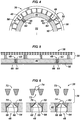
- each flow restriction element 48 comprises a nozzle 62 in the form of an insert which is inserted into a corresponding perforation or opening 64 formed radially through sidewall 50.
- the nozzle inserts 62 may be secured in their corresponding openings 64 by a variety of mechanisms.
- the nozzle inserts 62 may be threaded into or press fit into corresponding openings 64.
- the nozzle inserts 62 also may be tapered or conical to facilitate frictional engagement when press fit into corresponding opening 64. It should be noted that in other embodiments, the nozzles 62 may be formed in sidewall 50 without creating separate inserts received in corresponding openings.
- each nozzle insert 62 comprises a passage 66 through which inflowing gas is routed through sidewall 50 and into the interior 52 of base pipe 40.
- the size of each passage 66 as well as the number and pattern of inserts 62 may be calculated to achieve the desired pressure drop across the base pipe 40 and also the desired reduction in velocity of flowing fluid, e.g. inflowing or outflowing gas, to a flow rate below an erosion rate of the sand screen 38.
- the nozzle inserts 62 also may be formed from an erosion resistant material, such as a hardened material, carbide material, or other suitable material.
- the nozzles 62 may be designed with flow passages 66 each having an expanded portion 68 downstream of a passage entry opening 70.
- the expanded portion 68 may be designed as a tapered region with a taper having an increasing diameter in the direction of flowing fluid.
- the expanded portions 68 help prevent plugging of passages 66 if particles pass through screen openings 72, e.g. slots or pores, of sand screen 38.
- the entry opening 70 provides the desired flow area, but this region only extends a short length to help prevent plugging.
- nozzles 62 By choosing nozzles 62 having passages equal to or slightly larger than screen openings 72 of the sand screen 38, a self-healing effect is achieved. If the sand screen 38 undergoes any erosion, as illustrated by the widened screen opening 72 on the right side of Figure 6 , a particle 74 is able to pass through and plug the corresponding nozzle 62.
- the plugged passage 66 reduces the fluid flow flux in this area and reduces or eliminates any further erosion. Consequently, the diameter/area of passages 66 may be selected based on formation particle size to make sure the particles are able to plug the passage 66 in the event of regional failure of sand screen 38. In some applications, passages 66 may be smaller than screen opening 72 but then the nozzles are subject to unwanted plugging due to fines passing through the sand screen 38.
- the drainage layer 58 of the sand screen 38 may be separated into several compartments.
- the compartmentalization may be achieved by placing inserts or other types of flow blocking members in the axial flow channels of the drainage layer 58 to prevent movement of particles 74 in an axial direction along an exterior of the base pipe 40. Preventing particles 74 from flowing axially or tangentially along an outer surface of the base pipe 40 ensures that a significant portion of the sand screen will not fill with sand even if a small part of the sand screen 38 is eroded.
- the inserts or flow blocking members may comprise a ring in the drainage layer, a segment between structural members, e.g. between axial rods, of the sand screen, a shim placed between wrappings of the screen, or other suitable members designed to compartmentalize the screen and thus prevent any substantial transverse flow of fluid and particulates.
- each flow restriction element 48 comprises a small tube 76 disposed between an outer surface of the base pipe 40 and the surrounding sand screen 38.
- multiple tubes 76 are oriented generally longitudinally between a drainage layer of the sand screen 38 and the outer surface of base pipe 40, as best illustrated in Figure 8 .
- each tube 76 is routed to and coupled with the corresponding hole 54 extending through sidewall 50.
- each flow restriction element 48 provides a flow connection to the interior 52 of base pipe 40 and acts as a drain for inflowing fluid, e.g. gas, entering the sand screen 38. As a result, the gas flow approaching sand screen assembly 36 tends to converge towards these drainage points.
- inflowing fluid e.g. gas
- the focusing effect of the flow may be controlled, at least somewhat, by the slot/opening density of the sand screen 38 and/or by the cross-sectional configuration of the drainage layer 58, as illustrated schematically in Figure 9 which provides an example of a flow profile 78 across the sand screen 38.
- a more even flux is achieved with respect to fast flowing fluid, e.g. inflowing gas, approaching the sand screen assembly 36.
- fast flowing fluid e.g. inflowing gas
- a small pressure drop occurs as a fluid flows longitudinally/transversely within the sand screen 38 toward a flow restriction element 48 of base pipe 40.
- the sand screen assembly 36 may be designed so the pressure drop through the screen opening 72 is of a similar order of magnitude as the pressure drop along the drainage layer 58 over the distance between distant flow restriction elements 48.
- Desired patterns of flow restriction elements 48 may be selected and designed based on optimization of peak flow velocity versus average flow velocity. Knowledge of the peak flow velocity and the average flow velocity is used to design flow restriction element density and flow area to ensure the velocity approaching sand screen 38 stays below an erosion velocity, thereby reducing or preventing erosion of the sand screen 38.
- the overall well system 20 may be constructed to accommodate a variety of flow filtering applications in a variety of well environments while limiting or preventing erosion of the screen and other completion components. Accordingly, the number, type and configuration of components and systems within the overall system may be adjusted to accommodate different applications. For example, the size, number and configuration of the sand screen assemblies may vary from one application to another along the completion equipment. Additionally, many types of flow restriction elements and arrangements of those elements may be employed as dictated by the overall design of gas production equipment and by downhole environmental conditions. The base pipe configuration and the sand screen configuration also may be adjusted according to the specific application and environment. The sand screen assemblies and their erosion control elements may be combined into many types of well completions utilized in production and/or servicing operations. Also, the types and arrangements of other downhole equipment used in conjunction with the one or more sand screen assemblies may be selected according to the specific well related application in which the sand screen assemblies are employed.
Landscapes
- Engineering & Computer Science (AREA)
- Mining & Mineral Resources (AREA)
- Geology (AREA)
- Life Sciences & Earth Sciences (AREA)
- Fluid Mechanics (AREA)
- Environmental & Geological Engineering (AREA)
- Physics & Mathematics (AREA)
- General Life Sciences & Earth Sciences (AREA)
- Geochemistry & Mineralogy (AREA)
- Chemical & Material Sciences (AREA)
- Dispersion Chemistry (AREA)
- Filtering Materials (AREA)
- Filtration Of Liquid (AREA)
Claims (15)
- Verfahren zum Verhindern von Bauteilerosion in einer Bohrung mit hoher Fluidfließrate, umfassend:
Ausbilden eines Basisrohrs (40) mit mehreren, sich radial durch dieses hindurch erstreckenden Strömungsbegrenzungselementen (48, 62); und Platzieren eines Siebfilters (38) um das Basisrohr (40), um Feststoffe aus einem einströmenden Fluidstrom auszufiltern; gekennzeichnet durch:
Anordnen der mehreren Strömungsbegrenzungselemente (48) entlang des Basisrohrs (40) in einem vorbestimmten Muster, wobei das Muster der Strömungsbegrenzungselemente (48) durch Berechnung eines Gesamtströmungsbereichs bestimmt wird, um einen gewünschten Druckabfall über das Basisrohr (40) bereitzustellen und einen verteilten Zustrom von Fluid zu schaffen, der eine Fließrate des einströmenden Fluids über das gesamte Siebfilter (38) unterhalb einer Erosionsfließrate hält. - Verfahren gemäß Anspruch 1, wobei Ausbilden umfasst, die mehreren Strömungsbegrenzungselemente als in einer Seitenwandung des Basisrohrs (40) positionierte Düsen (62) auszubilden.
- Verfahren gemäß Anspruch 1, wobei Ausbilden umfasst, die mehreren Strömungsbegrenzungselemente (48) als Mündungskanäle (54) durch eine Seitenwandung des Basisrohrs (40) auszubilden.
- Verfahren gemäß Anspruch 1, wobei Ausbilden umfasst, die mehreren Strömungsbegrenzungselemente (48) als zwischen dem Basisrohr (40) und dem Siebfilter (38) positionierte Röhrenleitungen (76) auszubilden, wobei die Röhrenleitungen (76) mit Löchern (54) durch eine Seitenwandung des Basisrohrs (40) gekoppelt sind.
- Verfahren gemäß Anspruch 1, wobei Ausbilden umfasst, die mehreren Strömungsbegrenzungselemente (48) als Öffnungen (54) durch eine Seitenwandung des Basisrohrs (40) auszubilden, wobei die Öffnungen das Ein- bis Fünffache der Größe von Schlitzöffnungen durch das Siebfilter (38) betragen.
- Verfahren gemäß Anspruch 1, wobei Beabstanden umfasst, die mehreren Strömungsbegrenzungselemente (48) gleichmäßig entlang des Basisrohrs zu beabstanden, um einen kontrollierten, konstanten Druckabfall entlang des gesamten radial unter dem Siebfilter (38) befindlichen Basisrohrs (40) bereitzustellen.
- Verfahren gemäß Anspruch 2, das ferner ein Ausbilden der Düsen (62) als Düseneinsätze (62) umfasst, wobei jeder Düseneinsatz eine Öffnung (66) mit entlang der Richtung des Fluidstroms zunehmendem Durchmesser aufweist.
- Verfahren gemäß Anspruch 1, das ferner ein Ausbilden des Siebfilters (38) mit einer dem Basisrohr (40) benachbart positionierten Dränschicht (58) umfasst.
- Verfahren gemäß Anspruch 1, wobei Beabstanden umfasst, die mehreren Strömungsbegrenzungselemente (48) dahingehend örtlich festzulegen, einen variierenden Druckabfall entlang des Basisrohrs (40) bereitzustellen.
- Verfahren gemäß Anspruch 1, das ferner umfasst:
Bereitstellen eines Musters von Strömungsbegrenzungselementen (48) entlang des Basisrohrs (40), um einen kontrollierten Druckabfall über das Basisrohr (40) bereitzustellen; um einen Fluidstrom mit hoher Fließrate gleichmäßig entlang eines Sandsiebfilters (38) zu verteilen; und um die Fließrate des Fluids unterhalb einer Sandsiebfiltererosionsrate zu halten. - System zur Verwendung in einem Bohrloch, mit:einem Basisrohr (40), mit mehreren, sich von einer Außenseite zu einer Innenseite des Basisrohrs (40) erstreckenden Strömungsbegrenzungselementen (48); undeinem Sandsiebfilter, (38), das um das Basisrohr (40) herum positioniert ist, um Feststoffe aus einem einströmenden Gasstrom auszufiltern; dadurch gekennzeichnet, dass:
die mehreren Strömungsbegrenzungselemente (48) entlang des Basisrohrs (40) in einem vorbestimmten Muster angeordnet sind, wobei das Muster der Strömungsbegrenzungselemente (48) durch Berechnung eines Gesamtströmungsbereichs bestimmt wird, um einen gewünschten Druckabfall über das Basisrohr (40) bereitzustellen. - System gemäß Anspruch 11, wobei die mehreren Strömungsbegrenzungselemente (48) mehrere Düsen (62) umfassen.
- System gemäß Anspruch 11, wobei die mehreren Strömungsbegrenzungselemente (48) mehrere Mündungskanäle (54) umfassen.
- System gemäß Anspruch 11, wobei die mehreren Strömungsbegrenzungselemente (48) mehrere, mit mehreren Löchern (54) durch eine Seitenwandung des Basisrohrs (40) gekoppelte Röhrenleitungen (76) umfassen.
- System gemäß Anspruch 13, wobei der Gasstrom durch mehrere Siebfilteröffnungen des Sandsiebfilters (38) einen kleinen Druckabfall in der gleichen Größenordnung wie der Druckabfall entlang einer Außenseite des Basisrohrs zwischen entfernten Strömungsbegrenzungselementen (48) bereitstellt.
Applications Claiming Priority (2)
| Application Number | Priority Date | Filing Date | Title |
|---|---|---|---|
| US12/759,432 US8316952B2 (en) | 2010-04-13 | 2010-04-13 | System and method for controlling flow through a sand screen |
| PCT/US2011/031942 WO2011130168A2 (en) | 2010-04-13 | 2011-04-11 | System and method for controlling flow through a sand screen |
Publications (3)
| Publication Number | Publication Date |
|---|---|
| EP2550427A2 EP2550427A2 (de) | 2013-01-30 |
| EP2550427A4 EP2550427A4 (de) | 2017-07-05 |
| EP2550427B1 true EP2550427B1 (de) | 2019-08-07 |
Family
ID=44760098
Family Applications (1)
| Application Number | Title | Priority Date | Filing Date |
|---|---|---|---|
| EP11769377.0A Active EP2550427B1 (de) | 2010-04-13 | 2011-04-11 | System und verfahren zur steuerung des flusses durch ein sandsieb |
Country Status (4)
| Country | Link |
|---|---|
| US (1) | US8316952B2 (de) |
| EP (1) | EP2550427B1 (de) |
| AU (1) | AU2011240830B2 (de) |
| WO (1) | WO2011130168A2 (de) |
Families Citing this family (18)
| Publication number | Priority date | Publication date | Assignee | Title |
|---|---|---|---|---|
| CA2704896C (en) * | 2010-05-25 | 2013-04-16 | Imperial Oil Resources Limited | Well completion for viscous oil recovery |
| US20120061093A1 (en) * | 2010-09-09 | 2012-03-15 | Baker Hughes Incorporated | Multiple in-flow control devices and methods for using same |
| US9187987B2 (en) | 2011-10-12 | 2015-11-17 | Schlumberger Technology Corporation | System and method for controlling flow through a sand screen |
| US8925633B2 (en) | 2012-01-13 | 2015-01-06 | Baker Hughes Incorporated | Inflow control device with adjustable orifice and production string having the same |
| US9169724B2 (en) | 2012-02-23 | 2015-10-27 | Halliburton Energy Services, Inc. | Expandable conical tubing run through production tubing and into open hole |
| US8783349B2 (en) | 2012-05-04 | 2014-07-22 | Schlumber Technology Corporation | Compliant sand screen |
| US9273537B2 (en) | 2012-07-16 | 2016-03-01 | Schlumberger Technology Corporation | System and method for sand and inflow control |
| GB2521956B (en) * | 2012-10-29 | 2017-06-14 | Halliburton Energy Services Inc | Subterranean well tools with directionally controlling flow layer |
| WO2014163647A1 (en) | 2013-04-05 | 2014-10-09 | Halliburton Energy Services, Inc. | Controlling flow in a wellbore |
| CA2918791A1 (en) | 2013-07-25 | 2015-01-29 | Schlumberger Canada Limited | Sand control system and methodology |
| US10900338B2 (en) * | 2014-10-29 | 2021-01-26 | Schlumberger Technology Corporation | System and method for dispersing fluid flow from high speed jet |
| GB2548065B (en) * | 2015-02-13 | 2021-04-07 | Halliburton Energy Services Inc | Sand control screen assemblies with erosion-resistant flow paths |
| CA2902548C (en) * | 2015-08-31 | 2019-02-26 | Suncor Energy Inc. | Systems and method for controlling production of hydrocarbons |
| US20180328139A1 (en) * | 2017-05-12 | 2018-11-15 | Weatherford Technology Holdings, Llc | Temporary Barrier for Inflow Control Device |
| WO2020018183A1 (en) * | 2018-07-18 | 2020-01-23 | Exxonmobil Upstream Research Company | Reducing erosional peak velocity of fluid flow through sand screens |
| WO2020172092A1 (en) | 2019-02-20 | 2020-08-27 | Schlumberger Technology Corporation | Non-metallic compliant sand control screen |
| WO2022081440A1 (en) | 2020-10-13 | 2022-04-21 | Schlumberger Technology Corporation | Elastomer alloy for intelligent sand management |
| NL1044081B1 (en) * | 2021-07-02 | 2023-01-10 | Ir Msc Mark Gilbert Sisouw De Zilwa | Method and devices for unloading flow conduits and improving multi-phase flow capacity. |
Citations (1)
| Publication number | Priority date | Publication date | Assignee | Title |
|---|---|---|---|---|
| US5190102A (en) * | 1990-10-22 | 1993-03-02 | Otis Engineering Corporation | Sintered metal substitute for prepack screen aggregate |
Family Cites Families (17)
| Publication number | Priority date | Publication date | Assignee | Title |
|---|---|---|---|---|
| NO306127B1 (no) | 1992-09-18 | 1999-09-20 | Norsk Hydro As | Fremgangsmate og produksjonsror for produksjon av olje eller gass fra et olje- eller gassreservoar |
| US5896928A (en) * | 1996-07-01 | 1999-04-27 | Baker Hughes Incorporated | Flow restriction device for use in producing wells |
| US5881809A (en) * | 1997-09-05 | 1999-03-16 | United States Filter Corporation | Well casing assembly with erosion protection for inner screen |
| US6469743B1 (en) * | 1999-06-09 | 2002-10-22 | International Business Machines Corporation | Programmable external graphics/video port for digital video decode system chip |
| GB2371319B (en) | 2001-01-23 | 2003-08-13 | Schlumberger Holdings | Completion Assemblies |
| NO314701B3 (no) * | 2001-03-20 | 2007-10-08 | Reslink As | Stromningsstyreanordning for struping av innstrommende fluider i en bronn |
| NO318165B1 (no) | 2002-08-26 | 2005-02-14 | Reslink As | Bronninjeksjonsstreng, fremgangsmate for fluidinjeksjon og anvendelse av stromningsstyreanordning i injeksjonsstreng |
| US7055598B2 (en) * | 2002-08-26 | 2006-06-06 | Halliburton Energy Services, Inc. | Fluid flow control device and method for use of same |
| US7870898B2 (en) | 2003-03-31 | 2011-01-18 | Exxonmobil Upstream Research Company | Well flow control systems and methods |
| US7673678B2 (en) | 2004-12-21 | 2010-03-09 | Schlumberger Technology Corporation | Flow control device with a permeable membrane |
| EA014072B1 (ru) | 2005-09-30 | 2010-08-30 | Эксонмобил Апстрим Рисерч Компани | Скважинное устройство и способ завершения скважины, добычи и нагнетания |
| US7984760B2 (en) * | 2006-04-03 | 2011-07-26 | Exxonmobil Upstream Research Company | Wellbore method and apparatus for sand and inflow control during well operations |
| US7469743B2 (en) * | 2006-04-24 | 2008-12-30 | Halliburton Energy Services, Inc. | Inflow control devices for sand control screens |
| US7802621B2 (en) * | 2006-04-24 | 2010-09-28 | Halliburton Energy Services, Inc. | Inflow control devices for sand control screens |
| US20080041582A1 (en) * | 2006-08-21 | 2008-02-21 | Geirmund Saetre | Apparatus for controlling the inflow of production fluids from a subterranean well |
| US7832473B2 (en) * | 2007-01-15 | 2010-11-16 | Schlumberger Technology Corporation | Method for controlling the flow of fluid between a downhole formation and a base pipe |
| US20100122810A1 (en) * | 2008-11-19 | 2010-05-20 | Langlais Michael D | Well screens and method of making well screens |
-
2010
- 2010-04-13 US US12/759,432 patent/US8316952B2/en not_active Expired - Fee Related
-
2011
- 2011-04-11 AU AU2011240830A patent/AU2011240830B2/en not_active Ceased
- 2011-04-11 EP EP11769377.0A patent/EP2550427B1/de active Active
- 2011-04-11 WO PCT/US2011/031942 patent/WO2011130168A2/en not_active Ceased
Patent Citations (1)
| Publication number | Priority date | Publication date | Assignee | Title |
|---|---|---|---|---|
| US5190102A (en) * | 1990-10-22 | 1993-03-02 | Otis Engineering Corporation | Sintered metal substitute for prepack screen aggregate |
Also Published As
| Publication number | Publication date |
|---|---|
| AU2011240830B2 (en) | 2014-07-10 |
| US20110247813A1 (en) | 2011-10-13 |
| WO2011130168A3 (en) | 2012-01-12 |
| EP2550427A4 (de) | 2017-07-05 |
| AU2011240830A1 (en) | 2012-11-08 |
| US8316952B2 (en) | 2012-11-27 |
| WO2011130168A2 (en) | 2011-10-20 |
| EP2550427A2 (de) | 2013-01-30 |
Similar Documents
| Publication | Publication Date | Title |
|---|---|---|
| EP2550427B1 (de) | System und verfahren zur steuerung des flusses durch ein sandsieb | |
| US7775284B2 (en) | Apparatus for adjustably controlling the inflow of production fluids from a subterranean well | |
| US20080041582A1 (en) | Apparatus for controlling the inflow of production fluids from a subterranean well | |
| EP1953335A2 (de) | Vorrichtung zur Steuerung des Zuflusses von Produktionsflüssigkeiten aus einem Bohrloch | |
| CA2793364C (en) | Apparatus and method for controlling fluid flow between formations and wellbores | |
| US9512701B2 (en) | Flow control devices including a sand screen and an inflow control device for use in wellbores | |
| US8464793B2 (en) | Flow control system with sand screen | |
| US10053962B2 (en) | Prepacked sand screen assemblies | |
| US9353605B2 (en) | Flow distribution assemblies for preventing sand screen erosion | |
| US9187987B2 (en) | System and method for controlling flow through a sand screen | |
| US9828837B2 (en) | Flow control devices including a sand screen having integral standoffs and methods of using the same | |
| WO2014014651A1 (en) | System and method for sand and inflow control | |
| EP2815067B1 (de) | Flüssigkeitsbypass für ein rohr einer flusssteuerungsvorrichtung | |
| GB2499596A (en) | Downhole flow control |
Legal Events
| Date | Code | Title | Description |
|---|---|---|---|
| PUAI | Public reference made under article 153(3) epc to a published international application that has entered the european phase |
Free format text: ORIGINAL CODE: 0009012 |
|
| 17P | Request for examination filed |
Effective date: 20121024 |
|
| AK | Designated contracting states |
Kind code of ref document: A2 Designated state(s): AL AT BE BG CH CY CZ DE DK EE ES FI FR GB GR HR HU IE IS IT LI LT LU LV MC MK MT NL NO PL PT RO RS SE SI SK SM TR |
|
| DAX | Request for extension of the european patent (deleted) | ||
| A4 | Supplementary search report drawn up and despatched |
Effective date: 20170606 |
|
| RIC1 | Information provided on ipc code assigned before grant |
Ipc: E21B 43/12 20060101ALI20170530BHEP Ipc: E21B 43/08 20060101AFI20170530BHEP |
|
| STAA | Information on the status of an ep patent application or granted ep patent |
Free format text: STATUS: EXAMINATION IS IN PROGRESS |
|
| 17Q | First examination report despatched |
Effective date: 20180425 |
|
| GRAP | Despatch of communication of intention to grant a patent |
Free format text: ORIGINAL CODE: EPIDOSNIGR1 |
|
| STAA | Information on the status of an ep patent application or granted ep patent |
Free format text: STATUS: GRANT OF PATENT IS INTENDED |
|
| INTG | Intention to grant announced |
Effective date: 20181127 |
|
| GRAS | Grant fee paid |
Free format text: ORIGINAL CODE: EPIDOSNIGR3 |
|
| GRAJ | Information related to disapproval of communication of intention to grant by the applicant or resumption of examination proceedings by the epo deleted |
Free format text: ORIGINAL CODE: EPIDOSDIGR1 |
|
| GRAL | Information related to payment of fee for publishing/printing deleted |
Free format text: ORIGINAL CODE: EPIDOSDIGR3 |
|
| STAA | Information on the status of an ep patent application or granted ep patent |
Free format text: STATUS: EXAMINATION IS IN PROGRESS |
|
| GRAP | Despatch of communication of intention to grant a patent |
Free format text: ORIGINAL CODE: EPIDOSNIGR1 |
|
| STAA | Information on the status of an ep patent application or granted ep patent |
Free format text: STATUS: GRANT OF PATENT IS INTENDED |
|
| INTC | Intention to grant announced (deleted) | ||
| INTG | Intention to grant announced |
Effective date: 20190529 |
|
| RIN1 | Information on inventor provided before grant (corrected) |
Inventor name: MOEN, TERJE |
|
| GRAA | (expected) grant |
Free format text: ORIGINAL CODE: 0009210 |
|
| STAA | Information on the status of an ep patent application or granted ep patent |
Free format text: STATUS: THE PATENT HAS BEEN GRANTED |
|
| AK | Designated contracting states |
Kind code of ref document: B1 Designated state(s): AL AT BE BG CH CY CZ DE DK EE ES FI FR GB GR HR HU IE IS IT LI LT LU LV MC MK MT NL NO PL PT RO RS SE SI SK SM TR |
|
| REG | Reference to a national code |
Ref country code: GB Ref legal event code: FG4D |
|
| REG | Reference to a national code |
Ref country code: CH Ref legal event code: EP Ref country code: AT Ref legal event code: REF Ref document number: 1164163 Country of ref document: AT Kind code of ref document: T Effective date: 20190815 |
|
| REG | Reference to a national code |
Ref country code: DE Ref legal event code: R096 Ref document number: 602011061061 Country of ref document: DE |
|
| REG | Reference to a national code |
Ref country code: IE Ref legal event code: FG4D |
|
| REG | Reference to a national code |
Ref country code: NL Ref legal event code: MP Effective date: 20190807 |
|
| REG | Reference to a national code |
Ref country code: LT Ref legal event code: MG4D |
|
| REG | Reference to a national code |
Ref country code: NO Ref legal event code: T2 Effective date: 20190807 |
|
| PG25 | Lapsed in a contracting state [announced via postgrant information from national office to epo] |
Ref country code: BG Free format text: LAPSE BECAUSE OF FAILURE TO SUBMIT A TRANSLATION OF THE DESCRIPTION OR TO PAY THE FEE WITHIN THE PRESCRIBED TIME-LIMIT Effective date: 20191107 Ref country code: NL Free format text: LAPSE BECAUSE OF FAILURE TO SUBMIT A TRANSLATION OF THE DESCRIPTION OR TO PAY THE FEE WITHIN THE PRESCRIBED TIME-LIMIT Effective date: 20190807 Ref country code: SE Free format text: LAPSE BECAUSE OF FAILURE TO SUBMIT A TRANSLATION OF THE DESCRIPTION OR TO PAY THE FEE WITHIN THE PRESCRIBED TIME-LIMIT Effective date: 20190807 Ref country code: HR Free format text: LAPSE BECAUSE OF FAILURE TO SUBMIT A TRANSLATION OF THE DESCRIPTION OR TO PAY THE FEE WITHIN THE PRESCRIBED TIME-LIMIT Effective date: 20190807 Ref country code: PT Free format text: LAPSE BECAUSE OF FAILURE TO SUBMIT A TRANSLATION OF THE DESCRIPTION OR TO PAY THE FEE WITHIN THE PRESCRIBED TIME-LIMIT Effective date: 20191209 Ref country code: LT Free format text: LAPSE BECAUSE OF FAILURE TO SUBMIT A TRANSLATION OF THE DESCRIPTION OR TO PAY THE FEE WITHIN THE PRESCRIBED TIME-LIMIT Effective date: 20190807 Ref country code: FI Free format text: LAPSE BECAUSE OF FAILURE TO SUBMIT A TRANSLATION OF THE DESCRIPTION OR TO PAY THE FEE WITHIN THE PRESCRIBED TIME-LIMIT Effective date: 20190807 |
|
| REG | Reference to a national code |
Ref country code: AT Ref legal event code: MK05 Ref document number: 1164163 Country of ref document: AT Kind code of ref document: T Effective date: 20190807 |
|
| PG25 | Lapsed in a contracting state [announced via postgrant information from national office to epo] |
Ref country code: LV Free format text: LAPSE BECAUSE OF FAILURE TO SUBMIT A TRANSLATION OF THE DESCRIPTION OR TO PAY THE FEE WITHIN THE PRESCRIBED TIME-LIMIT Effective date: 20190807 Ref country code: ES Free format text: LAPSE BECAUSE OF FAILURE TO SUBMIT A TRANSLATION OF THE DESCRIPTION OR TO PAY THE FEE WITHIN THE PRESCRIBED TIME-LIMIT Effective date: 20190807 Ref country code: GR Free format text: LAPSE BECAUSE OF FAILURE TO SUBMIT A TRANSLATION OF THE DESCRIPTION OR TO PAY THE FEE WITHIN THE PRESCRIBED TIME-LIMIT Effective date: 20191108 Ref country code: RS Free format text: LAPSE BECAUSE OF FAILURE TO SUBMIT A TRANSLATION OF THE DESCRIPTION OR TO PAY THE FEE WITHIN THE PRESCRIBED TIME-LIMIT Effective date: 20190807 Ref country code: IS Free format text: LAPSE BECAUSE OF FAILURE TO SUBMIT A TRANSLATION OF THE DESCRIPTION OR TO PAY THE FEE WITHIN THE PRESCRIBED TIME-LIMIT Effective date: 20191207 Ref country code: AL Free format text: LAPSE BECAUSE OF FAILURE TO SUBMIT A TRANSLATION OF THE DESCRIPTION OR TO PAY THE FEE WITHIN THE PRESCRIBED TIME-LIMIT Effective date: 20190807 |
|
| PG25 | Lapsed in a contracting state [announced via postgrant information from national office to epo] |
Ref country code: TR Free format text: LAPSE BECAUSE OF FAILURE TO SUBMIT A TRANSLATION OF THE DESCRIPTION OR TO PAY THE FEE WITHIN THE PRESCRIBED TIME-LIMIT Effective date: 20190807 |
|
| PG25 | Lapsed in a contracting state [announced via postgrant information from national office to epo] |
Ref country code: DK Free format text: LAPSE BECAUSE OF FAILURE TO SUBMIT A TRANSLATION OF THE DESCRIPTION OR TO PAY THE FEE WITHIN THE PRESCRIBED TIME-LIMIT Effective date: 20190807 Ref country code: EE Free format text: LAPSE BECAUSE OF FAILURE TO SUBMIT A TRANSLATION OF THE DESCRIPTION OR TO PAY THE FEE WITHIN THE PRESCRIBED TIME-LIMIT Effective date: 20190807 Ref country code: AT Free format text: LAPSE BECAUSE OF FAILURE TO SUBMIT A TRANSLATION OF THE DESCRIPTION OR TO PAY THE FEE WITHIN THE PRESCRIBED TIME-LIMIT Effective date: 20190807 Ref country code: IT Free format text: LAPSE BECAUSE OF FAILURE TO SUBMIT A TRANSLATION OF THE DESCRIPTION OR TO PAY THE FEE WITHIN THE PRESCRIBED TIME-LIMIT Effective date: 20190807 Ref country code: RO Free format text: LAPSE BECAUSE OF FAILURE TO SUBMIT A TRANSLATION OF THE DESCRIPTION OR TO PAY THE FEE WITHIN THE PRESCRIBED TIME-LIMIT Effective date: 20190807 Ref country code: PL Free format text: LAPSE BECAUSE OF FAILURE TO SUBMIT A TRANSLATION OF THE DESCRIPTION OR TO PAY THE FEE WITHIN THE PRESCRIBED TIME-LIMIT Effective date: 20190807 |
|
| PG25 | Lapsed in a contracting state [announced via postgrant information from national office to epo] |
Ref country code: SK Free format text: LAPSE BECAUSE OF FAILURE TO SUBMIT A TRANSLATION OF THE DESCRIPTION OR TO PAY THE FEE WITHIN THE PRESCRIBED TIME-LIMIT Effective date: 20190807 Ref country code: CZ Free format text: LAPSE BECAUSE OF FAILURE TO SUBMIT A TRANSLATION OF THE DESCRIPTION OR TO PAY THE FEE WITHIN THE PRESCRIBED TIME-LIMIT Effective date: 20190807 Ref country code: IS Free format text: LAPSE BECAUSE OF FAILURE TO SUBMIT A TRANSLATION OF THE DESCRIPTION OR TO PAY THE FEE WITHIN THE PRESCRIBED TIME-LIMIT Effective date: 20200224 Ref country code: SM Free format text: LAPSE BECAUSE OF FAILURE TO SUBMIT A TRANSLATION OF THE DESCRIPTION OR TO PAY THE FEE WITHIN THE PRESCRIBED TIME-LIMIT Effective date: 20190807 |
|
| REG | Reference to a national code |
Ref country code: DE Ref legal event code: R097 Ref document number: 602011061061 Country of ref document: DE |
|
| PLBE | No opposition filed within time limit |
Free format text: ORIGINAL CODE: 0009261 |
|
| STAA | Information on the status of an ep patent application or granted ep patent |
Free format text: STATUS: NO OPPOSITION FILED WITHIN TIME LIMIT |
|
| PG2D | Information on lapse in contracting state deleted |
Ref country code: IS |
|
| 26N | No opposition filed |
Effective date: 20200603 |
|
| PG25 | Lapsed in a contracting state [announced via postgrant information from national office to epo] |
Ref country code: SI Free format text: LAPSE BECAUSE OF FAILURE TO SUBMIT A TRANSLATION OF THE DESCRIPTION OR TO PAY THE FEE WITHIN THE PRESCRIBED TIME-LIMIT Effective date: 20190807 |
|
| REG | Reference to a national code |
Ref country code: DE Ref legal event code: R119 Ref document number: 602011061061 Country of ref document: DE |
|
| REG | Reference to a national code |
Ref country code: NO Ref legal event code: MMEP |
|
| PG25 | Lapsed in a contracting state [announced via postgrant information from national office to epo] |
Ref country code: MC Free format text: LAPSE BECAUSE OF FAILURE TO SUBMIT A TRANSLATION OF THE DESCRIPTION OR TO PAY THE FEE WITHIN THE PRESCRIBED TIME-LIMIT Effective date: 20190807 |
|
| REG | Reference to a national code |
Ref country code: CH Ref legal event code: PL |
|
| PG25 | Lapsed in a contracting state [announced via postgrant information from national office to epo] |
Ref country code: LU Free format text: LAPSE BECAUSE OF NON-PAYMENT OF DUE FEES Effective date: 20200411 Ref country code: NO Free format text: LAPSE BECAUSE OF NON-PAYMENT OF DUE FEES Effective date: 20200430 Ref country code: DE Free format text: LAPSE BECAUSE OF NON-PAYMENT OF DUE FEES Effective date: 20201103 Ref country code: LI Free format text: LAPSE BECAUSE OF NON-PAYMENT OF DUE FEES Effective date: 20200430 Ref country code: CH Free format text: LAPSE BECAUSE OF NON-PAYMENT OF DUE FEES Effective date: 20200430 |
|
| REG | Reference to a national code |
Ref country code: BE Ref legal event code: MM Effective date: 20200430 |
|
| PG25 | Lapsed in a contracting state [announced via postgrant information from national office to epo] |
Ref country code: BE Free format text: LAPSE BECAUSE OF NON-PAYMENT OF DUE FEES Effective date: 20200430 |
|
| GBPC | Gb: european patent ceased through non-payment of renewal fee |
Effective date: 20200411 |
|
| PG25 | Lapsed in a contracting state [announced via postgrant information from national office to epo] |
Ref country code: IE Free format text: LAPSE BECAUSE OF NON-PAYMENT OF DUE FEES Effective date: 20200411 Ref country code: GB Free format text: LAPSE BECAUSE OF NON-PAYMENT OF DUE FEES Effective date: 20200411 |
|
| PG25 | Lapsed in a contracting state [announced via postgrant information from national office to epo] |
Ref country code: MT Free format text: LAPSE BECAUSE OF FAILURE TO SUBMIT A TRANSLATION OF THE DESCRIPTION OR TO PAY THE FEE WITHIN THE PRESCRIBED TIME-LIMIT Effective date: 20190807 Ref country code: CY Free format text: LAPSE BECAUSE OF FAILURE TO SUBMIT A TRANSLATION OF THE DESCRIPTION OR TO PAY THE FEE WITHIN THE PRESCRIBED TIME-LIMIT Effective date: 20190807 |
|
| PG25 | Lapsed in a contracting state [announced via postgrant information from national office to epo] |
Ref country code: MK Free format text: LAPSE BECAUSE OF FAILURE TO SUBMIT A TRANSLATION OF THE DESCRIPTION OR TO PAY THE FEE WITHIN THE PRESCRIBED TIME-LIMIT Effective date: 20190807 |
|
| PG25 | Lapsed in a contracting state [announced via postgrant information from national office to epo] |
Ref country code: FR Free format text: LAPSE BECAUSE OF NON-PAYMENT OF DUE FEES Effective date: 20200430 |