EP2550202B1 - Labelling machine - Google Patents
Labelling machine Download PDFInfo
- Publication number
- EP2550202B1 EP2550202B1 EP10717876.6A EP10717876A EP2550202B1 EP 2550202 B1 EP2550202 B1 EP 2550202B1 EP 10717876 A EP10717876 A EP 10717876A EP 2550202 B1 EP2550202 B1 EP 2550202B1
- Authority
- EP
- European Patent Office
- Prior art keywords
- cam
- along
- receiving member
- path
- track
- Prior art date
- Legal status (The legal status is an assumption and is not a legal conclusion. Google has not performed a legal analysis and makes no representation as to the accuracy of the status listed.)
- Not-in-force
Links
- 238000002372 labelling Methods 0.000 title claims description 42
- 238000006073 displacement reaction Methods 0.000 claims description 9
- 238000000034 method Methods 0.000 description 12
- 239000003292 glue Substances 0.000 description 10
- 238000003780 insertion Methods 0.000 description 6
- 230000037431 insertion Effects 0.000 description 6
- 239000011800 void material Substances 0.000 description 6
- 238000003466 welding Methods 0.000 description 6
- 229920006257 Heat-shrinkable film Polymers 0.000 description 5
- 239000000463 material Substances 0.000 description 4
- 230000001360 synchronised effect Effects 0.000 description 3
- 238000005452 bending Methods 0.000 description 2
- 238000010380 label transfer Methods 0.000 description 2
- 230000002093 peripheral effect Effects 0.000 description 2
- 230000000717 retained effect Effects 0.000 description 2
- 230000004913 activation Effects 0.000 description 1
- 230000000712 assembly Effects 0.000 description 1
- 238000000429 assembly Methods 0.000 description 1
- 235000013361 beverage Nutrition 0.000 description 1
- 238000010438 heat treatment Methods 0.000 description 1
- 238000011144 upstream manufacturing Methods 0.000 description 1
Images


Classifications
-
- B—PERFORMING OPERATIONS; TRANSPORTING
- B65—CONVEYING; PACKING; STORING; HANDLING THIN OR FILAMENTARY MATERIAL
- B65C—LABELLING OR TAGGING MACHINES, APPARATUS, OR PROCESSES
- B65C3/00—Labelling other than flat surfaces
- B65C3/06—Affixing labels to short rigid containers
- B65C3/065—Affixing labels to short rigid containers by placing tubular labels around the container
-
- B—PERFORMING OPERATIONS; TRANSPORTING
- B65—CONVEYING; PACKING; STORING; HANDLING THIN OR FILAMENTARY MATERIAL
- B65C—LABELLING OR TAGGING MACHINES, APPARATUS, OR PROCESSES
- B65C9/00—Details of labelling machines or apparatus
- B65C9/02—Devices for moving articles, e.g. containers, past labelling station
- B65C9/04—Devices for moving articles, e.g. containers, past labelling station having means for rotating the articles
-
- B—PERFORMING OPERATIONS; TRANSPORTING
- B65—CONVEYING; PACKING; STORING; HANDLING THIN OR FILAMENTARY MATERIAL
- B65C—LABELLING OR TAGGING MACHINES, APPARATUS, OR PROCESSES
- B65C9/00—Details of labelling machines or apparatus
-
- B—PERFORMING OPERATIONS; TRANSPORTING
- B65—CONVEYING; PACKING; STORING; HANDLING THIN OR FILAMENTARY MATERIAL
- B65C—LABELLING OR TAGGING MACHINES, APPARATUS, OR PROCESSES
- B65C9/00—Details of labelling machines or apparatus
- B65C9/08—Label feeding
- B65C9/18—Label feeding from strips, e.g. from rolls
- B65C9/1803—Label feeding from strips, e.g. from rolls the labels being cut from a strip
- B65C9/1815—Label feeding from strips, e.g. from rolls the labels being cut from a strip and transferred by suction means
-
- B—PERFORMING OPERATIONS; TRANSPORTING
- B65—CONVEYING; PACKING; STORING; HANDLING THIN OR FILAMENTARY MATERIAL
- B65C—LABELLING OR TAGGING MACHINES, APPARATUS, OR PROCESSES
- B65C9/00—Details of labelling machines or apparatus
- B65C9/0065—Cutting tubular labels from a web
Definitions
- the present Invention relates to a labelling machine for applying labels on respective articles, such as bottles or generic containers, which the following description will refer to, although this is in no way intended to limit the scope of protection as defined by the accompanying claims.
- labelling machines are used to apply labels to containers or articles of all sort.
- two alternative techniques can be provided to attach the labels on the external surface of respective bottles.
- the back surfaces of the labels (commonly called “roll labels”) are covered with glue and are stuck onto the external surfaces of the bottles.
- the tubular labels are heated to fit and adhere onto the bottles.
- tubular labels are obtained by:
- a particular type of labelling machine which serves to bend and weld labels in a tubular configuration and then to produce insertion of the bottles into the so formed tubular labels before the heating operation.
- This kind of machine basically comprises a carousel rotating about a vertical axis to define a circular path, along which it receives a succession of unlabelled bottles by a bottle input wheel and, then, a succession of rectangular or square labels by a label input wheel, produces application of the labels in a tubular configuration onto the respective bottles, and releases the labelled bottles to an output wheel.
- the carousel comprises a plurality of labelling units which are equally spaced along a peripheral edge of the carousel and are moved by the latter along the above-mentioned circular path.
- Each labelling unit comprises a supporting assembly adapted to support the bottom wall of a relative bottle and an upper retainer adapted to cooperate with the top portion of such bottle, to hold it in a vertical position during the rotation of the carousel about its vertical axis.
- Each supporting assembly comprises a vertical hollow supporting mount, secured to a horizontal plane of a rotary frame of the carousel; and a cylindrical receiving member, which engages the supporting mount in sliding and rotating manner with respect to its vertical axis, and is adapted to carry a relative bottle on its top surface and a relative label on its lateral surface.
- the receiving members are displaced by a cam and tappet device between a raised position and a lowered position, while moving along the above mentioned circular path.
- each receiving member In the lowered position, the receiving member is fully retracted within the relative supporting mount, so that the top surface of each receiving member is flush with the top surface of the supporting mount. At the output wheel and at the bottle input wheel, each receiving member is located in its lowered position, so that the bottles are transferred onto and from the carousel along the same transfer horizontal plane.
- each receiving member protrudes from a top surface of the relative supporting mount and is adapted to receive a relative label on its lateral surface from the label input wheel; in particular, the label is wrapped around the receiving member such that the opposite vertical edges of the label overlap one another.
- the receiving member is rotated about its vertical axis during the transfer of the label from the label input wheel.
- the label is retained on the lateral surface of the receiving member by suction; for this purpose, at least a region of the lateral surface of the receiving member is provided with a plurality of holes, which are connected to a pneumatic suction device.
- the suction is released and the receiving member is lowered, so as to produce the insertion of the relative bottle downwards inside the tubular label, therefore making the ensemble of the bottle and the surrounding label ready to be transferred to the output wheel.
- Patent document WO 2004/020291 A1 discloses a labelling machine according to the preamble of claim 1.
- Number 1 in Figure 1 indicates as a whole a labelling machine for applying labels 2 (shown with a grey shadow in Figures 2 and 3 ) to respective articles or more specifically containers, particularly bottles 3, each of which ( Figures 1 to 3 ) extends along a longitudinal axis A, comprises a bottom wall 4 substantially perpendicular to axis A, and has a top neck 5 substantially coaxial with axis A.
- Machine 1 comprises a conveying device that serves to bend and weld labels 2 in a tubular configuration ( Figure 3 ) and to produce insertion of bottles 3 downwards into the so formed tubular labels 2.
- the conveying device comprises a carousel 7, which is mounted to rotate continuously (anticlockwise in Figure 1 ) about a respective vertical axis B perpendicular to the Figure 1 plane.
- the carousel 7 receives a succession of unlabelled bottles 3 from an input wheel 8, which cooperates with carousel 7 at a transfer station 9 and is mounted to rotate about a respective longitudinal axis C parallel to axis B.
- the rotation of the input wheel 8 is continuous and synchronized with the rotation of carousel 7.
- the carousel 7 also receives a succession of rectangular or square labels 2 from an input drum 10, which cooperates with carousel 7 at a feeding station 11 and is mounted to rotate continuously about a respective longitudinal axis D parallel to axes B and C.
- the carousel 7 releases a succession of labelled bottles 3 to an output wheel 12, which cooperates with carousel 7 at a transfer station 13 and is mounted to rotate about a respective longitudinal axis E parallel to axes B, C and D.
- the rotation of the output wheel 12 is continuous and synchronized with the rotation of carousel 7.
- the carousel 7 comprises a plurality of operating or labelling units 15, which are equally spaced about axis B, are mounted along a peripheral edge of carousel 7, and are moved by carousel 7 along a circular path P extending about axis B and through transfer stations 9, 11 and 13. As shown in Figure 1 , transfer station 11 is arranged, along path P, downstream of transfer station 9 and upstream of transfer station 13.
- the units 15 are secured to a horizontal rotary table 14 of carousel 7, have respective axes F parallel to axes B, C, D, E and extend coaxially through respective holes (not shown) of the rotary table 14 and on both sides of such table.
- Each unit 15 is adapted to receive a relative bottle 3 from input wheel 8 in a vertical position, i.e. coaxially with the relative axis F, and to hold said bottle 3 in such position along path P from transfer station 9 to transfer station 13.
- Units 15 being identical to each other, only one is described below for the sake of simplicity and clarity; it is clear that the features described hereafter are common to all the labelling units 15.
- unit 15 comprises, above the rotary table 14 of carousel 7, a supporting assembly 17 adapted to support the bottom wall 4 of the relative bottle 3 and an upper retainer 18 adapted to cooperate with the top neck 5 of the bottle 3.
- supporting assembly 17 comprises:
- the top end of the receiving member 22 is defined by a support plate 21, on which the bottle 3 rests.
- the support plate 21 is carried by a top portion of the lateral wall 23 via the interposition of a bearing (not visible), so as to be angularly free from lateral wall 23. In this way, rotational movements of the lateral wall 23 about axis F are not transmitted to the bottle 3.
- Receiving member 22 can be moved along axis F between a lowered position and a raised position by means of a cam and tappet device 24, which will be described later in greater detail.
- the receiving member 22 In the lowered position, the receiving member 22 is completely retracted within the supporting mount 20, so that support plate 21 is substantially flush with a top surface 25 of the supporting mount 20.
- receiving member 22 In the raised position, receiving member 22 protrudes from the top surface 25 of the supporting mount 20 and is adapted to receive, on the outer surface of its lateral wall 23, a label 2 made of heat-shrinkable film material from the input drum 10.
- labels 2 are cut in a know manner from a web 26 by a cutting device 27 (schematically shown) and fed to the input drum 10, which in turn feeds the cut labels 2 to the carousel 7.
- machine 1 can work to apply two alternative kinds of labels 2 onto the bottles 3.
- labels made of heat-shrinkable film material are fed by the input drum 10, respectively, onto the lateral walls 23 of the receiving members 22, while the latter are located in the raised position.
- labels 2 having glue on their back surfaces are fed by the input drum 10 directly onto the lateral surfaces of respective bottles 3, while the receiving members 22 are maintained in their lowered position.
- back surfaces of cut labels 2 receive glue from a glue dispenser or glue applicator 29 (schematically shown), while front surfaces of cut labels 2 rest against a lateral surface 30 of the input drum 10.
- the horizontal position of the input drum 10 with respect to the carousel 7 is adjusted when the labelling technique has to be changed, in order to bring input drum 10 closer to axes F when glued labels have to be applied onto the lateral surfaces of the bottles 3 or to move input drum 10 away when heat-shrinkable labels have to be wrap around the respective receiving members 22.
- front surfaces of cut labels 2 are retained on the lateral surface 30 by suction; in particular, the lateral surface 30 is divided into a given number, three in the embodiment shown, of suction regions 31, which are equally spaced about axis D, are each provided with a plurality of through holes 32 connected to a pneumatic suction device (known per se and not shown) and are adapted to cooperate with respective labels 2.
- a pneumatic suction device known per se and not shown
- lateral wall 23 of each receiving member 22 is provided with a plurality of through holes 33, in turn connected to a pneumatic suction device (not shown) so as to retain the relative label 2 made of heat-shrinkable film material on its outer surface by suction.
- each receiving member 22 is rotated about the relative axis F in order to produce the complete wrapping of the relative label 2, coming from input drum 10, on its outer surface.
- each label 2, fed by input drum 10, is wrapped around the relative receiving member 22 so as to form a cylinder with the opposite vertical edges 34 overlapped one another.
- Suction portion 36 has an arc-shaped cross section along a plane orthogonal to axis F and is sized in the circumferential direction so as to cooperate with two portions 37 of the relative label 2, which are adjacent, respectively, to the vertical edges 34.
- suction portion 36 is divided into two distinct vertical regions 38, 39 by an elastically deformable, vertical strip pad 40, on which vertical edges 34 of a relative label 2 are placed in an overlapped configuration.
- Strip pad 40 defines, in a known manner, the contrasting element for a welding device 44 (known per se and only schematically shown in Figure 1 ), arranged in front of, and in a radially inner position than, lateral wall 23 of receiving member 22 and adapted to weld the overlapped edges 34 of the relative label 2 so as to produce a tubular configuration of such label.
- each welding device 44 is coupled in fixed position to the supporting mount 20 of the relative unit 15 by means of a bracket 45 ( Figure 4 ).
- Regions 38, 39 are located on opposite sides of strip pad 40.
- Holes 33 communicate with the above mentioned pneumatic suction device through an inner space of the receiving member 22 and through an inner space in a top portion 42 of the supporting mount 20 ( Figure 4 ).
- the inner spaces of the receiving member 22 and the top portion 42 communicate with each other in a manner not shown.
- driving shaft 47 which is coaxial with the receiving member 22, extends through the supporting mount 20 and the receiving member 22 and is coupled in fixed position to bottom and top portions 48, 49 of the receiving member 22 in a manner not described in detail. Therefore, driving shaft 47 and lateral wall 23 of receiving member 22 are axially and angularly fixed to each other, so that any displacement transmitted to driving shaft 47 results in a corresponding displacement of lateral wall 23.
- Rotation of the driving shaft 47 is synchronized with the rotation of the input drum 10 and with the rotation of the carousel 7 and is operated by an actuator 46 (schematically shown in Figures 2 and 3 ), which is carried by the rotary table 14, is arranged underneath rotary table 14 and, in particular, is secured to a bottom surface of the rotary table 14.
- the cam and tappet device 24 comprises a cam device 51 ( Figure 5 ) and, for each unit 15, a relative cam follower 52, which is defined, in particular, by a roller located outside of the supporting mount 20 and mounted on an outer end portion 54 of a supporting pin 55, so as to be axially fixed and freely rotatable with respect to an axis 56 of the supporting pin 55.
- Supporting pin 55 extends radially with respect to axes B and F through a slot 58, which is made in a lateral wall of the supporting mount 20 on the outer side with respect to axis B, i.e. on the side opposite to welding device 44 and bracket 45.
- Supporting pin 55 has an end portion 59 axially opposite to end portion 54 and fixed with respect to a collar 60.
- Collar 60 is coaxial with driving shaft 47 and is coupled to driving shaft 47 by means of bearings 62, so as to be angularly free from driving shaft 47 and lateral wall 23 and to be axially fixed with respect to driving shaft 47 and lateral wall 23.
- collar 60 has an outer lateral surface slidingly coupled to the inner surface 63 of the supporting mount 20, so as to be axially guided between an upper position and a lower position.
- end portion 59 is coupled to collar 60 by means of an annular element 64, which is fastened to supporting pin 55 and to a side portion of collar 60, and is guided by slot 58 in a direction parallel to axis F. Therefore, slot 58 defines a constraint that prevents collar 60 and cam follower 52 from rotating about axis F. Therefore, any displacement transmitted to cam follower 52 results in an axial displacement of the driving shaft 47 and receiving member 22 between the lowered and raised positions.
- a spring 65 is provided inside the supporting mount 20 to push collar 60 upwards and, therefore, avoid axial play during displacement of cam follower 52.
- the cam device 51 is defined by an annular structure 66, which is fixed and extends along path P around the units 15 that are transferred by carousel 7.
- Cam device 51 can be adjusted to be set in a first configuration, in which cam followers 52 move along a track R, or in a second configuration, in which cam followers move along a track Q.
- cam device 51 comprises two cams 67,68, which alternately can be engaged by cam followers 52 and define, respectively, the tracks Q,R.
- Track Q of cam 67 is used to perform the second labelling technique, is parallel to the circular path P of the units 15 and lies on a horizontal plane, i.e. a plane perpendicular to axis B, in order to maintain all the engaging cam followers 52 at a given height, that corresponds to the lowered position of the receiving members 22.
- track R of cam 68 is shaped so as to move the cam followers 52 along the respective slots 58 to perform lifting and lowering of the respective receiving members 22 when machine 1 is used according to the first labelling technique.
- Figure 1 shows the rotation angles of the carousel 7 about axis B when such first labelling technique is performed: angle ⁇ refers to the lifting movement of the receiving members 22 from the lowered position to the raised position, angle ⁇ refers to the label transfer from the input drum 10 to the receiving members 22, angle ⁇ refers to the welding operation on the overlapped edges 34 of the tubular labels 2, and angle ⁇ refers to the downward movement of the receiving members 22 to produce insertion of the bottles 3 within the corresponding tubular labels 2.
- Track R comprises:
- Cam and tappet device 24 comprises a selection device 75 to set cam device 51 in the first or the second configuration.
- Selection device 75 comprises two switch devices 76, 77 located, respectively, at points 70b and 70a, i.e. where ramps 72,73 meet track Q: switch device 76 comprise at least one element that can be moved in two positions, to deviate the cam followers 52 arriving from portion 70 into ramp 72 or, respectively, into a remaining portion 78 of track Q; analogously switch device 77 comprise at least one element that can be moved in two positions, to channel cam followers 52 from ramp 73 or, respectively, from portion 78 into portion 70.
- the movement of the element or, the elements, of switch device 76 set one of two guides 76a,76b at point 70b; analogously, the movement of the element or, the elements, of switch device 77 set one of two guides 77a,77b at point 70a.
- guides 76a and 77a join portion 70 to ramps 72,73; in the meantime, guides 76b and 77b are located out of path R, in particular under cams 67,68, so as not to be engaged by cam followers 52.
- guides 76b and 77b join portion 70 to portion 78; in the meantime, guides 76a and 77a are located out of path Q, in particular over cam 67, so as not to be engaged by cam followers 52.
- Switch device 76,77 comprise respective actuators 82,83, located beneath cam 67, controlled to move the above-mentioned movable elements and select guide 76a or 76b and, respectively, select guide 77a or 77b.
- elements of switch devices 76 are three in number, are indicated by reference numbers 80a,80b,80c, are arranged side by side along a direction parallel to track Q and path P, and are symmetrical to elements 81c,81b,81a of switch device 77, with respect to a halfway plane on which axis B lies.
- elements 80a,80b,80c and elements 81a,81b,81c can slide along directions parallel to axes B and F under the action of the actuators 82,83.
- Each of elements 80a,80b,80c comprises a relative portion of guide 76a and a relative portion of guide 77a.
- each of elements 81a,81b,81c comprises a relative portion of guide 76b and a relative portion of guide 77b.
- Figure 6a-6h schematically show a sequence of steps to adjust the cam device 51 from the first configuration to the second configuration, preferably with a step-by-step rotating movement of the carousel 7.
- the first cam follower 52a to be deviated into track Q is shown in grey shadow, for sake of clarity.
- the width of elements 80a,80b,80c,81a,81b,81c is equal to half the pitch between the cam followers 52, and is higher than the diameter of each cam follower 52.
- the third element 80c becomes void and is then switched to remove guide 76a and set guide 76b. In this way, cam follower 52a follows guide 76b of the third element 80c ( Figure 6d ) and afterwards portion 78 of track Q.
- cam follower 52a When cam follower 52a is at the end of portion 78 ( Figure 6e ), cam follower 52b engages guide 77a the second element 81b, and the first element 81a and the third element 81c are void. In this condition, the first element 81a is switched to remove guide 77a and set guide 77b.
- cam follower 52a engages guide 77b of the first element 81a ( Figure 6f )
- cam follower 52b engages guide 77a of the third element 81c.
- the second element 81b is void and can be switched to remove guide 77a and set guide 77b.
- a change of the cam device 51 from the second configuration to the first configuration can be performed in an analogous manner, by switching elements 80a,80b,80c and 81a,81b,81c in sequence to progressively set guide 76a instead of guide 76b and progressively set guide 77a instead of guide 77b.
- the retainer 18, corresponding to the described supporting assembly 17 comprises, in a known manner, a cylindrical movable member 86, which protrudes vertically from an upper rotary portion 87 of carousel 7, can be displaced along the relative axis F and has a bell-shaped free end portion 88 adapted to cooperate with the top neck 5 of the bottle 3 carried by such supporting assembly 17.
- each movable member 86 are controlled in a known manner so as to maintain the same distance between its end portion 88 and the corresponding plate 21, during the movement of the relative unit 15 along path P from transfer station 9 to transfer station 13, independently of the vertical displacement of the receiving member 22 between the lowered and the raised positions, and so as to increase such distance at transfer stations 9, 13.
- bottles 3 are securely hold in their vertical positions during the travel from station 9 to station 13 and are free to be transferred at such stations 9 and 13 from input wheel 8 and to output wheel 12, respectively.
- ramp 72 of cam 68 moves the driving shaft 47 along axis F, so producing a translational movement of the receiving member 22 towards the desired raised position.
- the input drum 10 reaches an angular position around axis D adapted to put the label 2 into contact with the receiving member 22 passing through such station; in this condition (angle ⁇ ), a pure rotational movement of lateral wall 23 about axis F is obtained by operating the actuator 46, to produce complete wrapping of the label 2 around such lateral wall 23 ( Figure 3 ).
- the label 2 When the label 2 reaches a cylindrical configuration with the opposite vertical edges 34 overlapped one another and arranged on strip pad 40, the label 2 is ready to be welded along the edges 34 by activation of the welding device 44 (angle y).
- ramp 73 of cam 68 causes the receiving member 22 to return towards the lowered position within the relative supporting mount 20, so as to produce the insertion of the bottle 3 inside the so formed tubular label 2.
- a heat-shrinking step (not shown) can be then performed on the bottles 3 exiting from the carousel 7 to obtain shrinking and adhesion of the label 2 to the bottle external surface.
- the selection device 75 is operated to change configuration of the cam device 51. Accordingly, cam followers 52 change their track from cam 68 to cam 67, along one turn of carousel 7 about axis B.
- receiving members 22 of units 15 remain in the lowered position, within the relative supporting mount 20, along all the path P. In this condition, it is possible to feed labels 2 (called “roll-labels") made of a material different from heat-shrinkable film.
- glue dispenser or glue applicator 29 is activated to apply glue on the back surfaces of such labels 2, and the position of input drum 10 is adjusted to bring the back surface of labels 2 directly onto the outer surface of the respective bottles 3, without the need of the receiving members 22.
- cam device 51 permits to use the same machine 1 for processing either the so-called “roll labels”, to be covered with glue and to be stuck directly onto the external surfaces of the bottles 3, or the so called “sleeve labels”, to be wrapped and shrunk around the bottles 3.
- the change in the labelling technique only requires to operate the selection device 76 without dismantling and reassembling the cam and tappet device 24.
- the number of elements 80,81 in each of switch devices 76,77, the width of elements 80,81 along track Q, and the movement of elements 80,81 with respect to structure 66 could be different from the ones envisaged by way of example.
Landscapes
- Labeling Devices (AREA)
Description
- The present Invention relates to a labelling machine for applying labels on respective articles, such as bottles or generic containers, which the following description will refer to, although this is in no way intended to limit the scope of protection as defined by the accompanying claims.
- As it is generally known, labelling machines are used to apply labels to containers or articles of all sort. Typically, for beverage bottles or vessels, two alternative techniques can be provided to attach the labels on the external surface of respective bottles. According to a first technique, the back surfaces of the labels (commonly called "roll labels") are covered with glue and are stuck onto the external surfaces of the bottles. According to a second technique, after having placed tubular labels made of heat-shrinkable film (commonly called "sleeve labels") around respective bottles, the tubular labels are heated to fit and adhere onto the bottles.
- In particular, these tubular labels are obtained by:
- cutting a web unwound from a supply roll into a plurality of rectangular or square labels;
- bending each label in a cylindrical configuration such that the opposite vertical edges overlap one another; and
- welding the overlapped edges of each cylindrical label.
- A particular type of labelling machine is known which serves to bend and weld labels in a tubular configuration and then to produce insertion of the bottles into the so formed tubular labels before the heating operation. This kind of machine basically comprises a carousel rotating about a vertical axis to define a circular path, along which it receives a succession of unlabelled bottles by a bottle input wheel and, then, a succession of rectangular or square labels by a label input wheel, produces application of the labels in a tubular configuration onto the respective bottles, and releases the labelled bottles to an output wheel.
- More specifically, the carousel comprises a plurality of labelling units which are equally spaced along a peripheral edge of the carousel and are moved by the latter along the above-mentioned circular path.
- Each labelling unit comprises a supporting assembly adapted to support the bottom wall of a relative bottle and an upper retainer adapted to cooperate with the top portion of such bottle, to hold it in a vertical position during the rotation of the carousel about its vertical axis.
- Each supporting assembly comprises a vertical hollow supporting mount, secured to a horizontal plane of a rotary frame of the carousel; and a cylindrical receiving member, which engages the supporting mount in sliding and rotating manner with respect to its vertical axis, and is adapted to carry a relative bottle on its top surface and a relative label on its lateral surface.
- The receiving members are displaced by a cam and tappet device between a raised position and a lowered position, while moving along the above mentioned circular path.
- In the lowered position, the receiving member is fully retracted within the relative supporting mount, so that the top surface of each receiving member is flush with the top surface of the supporting mount. At the output wheel and at the bottle input wheel, each receiving member is located in its lowered position, so that the bottles are transferred onto and from the carousel along the same transfer horizontal plane.
- In the raised position, each receiving member protrudes from a top surface of the relative supporting mount and is adapted to receive a relative label on its lateral surface from the label input wheel; in particular, the label is wrapped around the receiving member such that the opposite vertical edges of the label overlap one another. In order to produce this complete wrapping, the receiving member is rotated about its vertical axis during the transfer of the label from the label input wheel. The label is retained on the lateral surface of the receiving member by suction; for this purpose, at least a region of the lateral surface of the receiving member is provided with a plurality of holes, which are connected to a pneumatic suction device.
- After having welded the overlapping edges of the tubular label, the suction is released and the receiving member is lowered, so as to produce the insertion of the relative bottle downwards inside the tubular label, therefore making the ensemble of the bottle and the surrounding label ready to be transferred to the output wheel.
- The known labelling machines of this kind, working with the so-called "sleeve labels", are not suitable to work also with the so-called "roll labels", because the latter have to be stuck to the external surfaces of the bottles without providing vertically movable receiving members, i.e. without vertically moving the bottles. Indeed, in carousels provided to support and transfer bottles onto which labels are applied by means of glue, the supporting assemblies of the labelling units are simplified in comparison to the above described ones.
- Patent document
WO 2004/020291 A1 discloses a labelling machine according to the preamble of claim 1. - A need is felt to provide a single machine that can be configured by means of a relatively low number of operations to apply either the so-called "sleeve labels" or the so-called "roll labels", without removing or changing components from all the labelling units of the carousel.
- It is an object of the present invention to provide a labelling machine, which allows to meet the above mentioned needs in a straightforward and low-cost manner.
- This object is achieved by a labelling machine as claimed in claim 1.
- A non-limiting embodiment of the present invention will be described by way of example with reference to the accompanying drawings, in which:
-
Figure 1 shows a schematic plan view, with parts removed for clarity, of a labelling machine in accordance with the teachings of the present invention; -
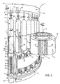
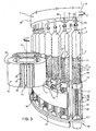
Figures 2 and3 are larger-scale and partial views in perspective of the labelling machine ofFigure 1 , in proximity of a label transfer station; -
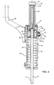
Figure 4 shows a section, along a vertical section plane and with parts removed for clarity, of a labelling unit of the labelling machine ofFigures 1-3 ; -
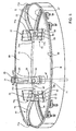
Figure 5 shows a larger-scale view in perspective, with parts removed for clarity, of a configurable cam and tappet device of the labelling machine ofFigures 1-3 ; and -
Figures 6a-6h schematically show a sequence of operations to set the cam and tappet device ofFigure 5 from a first configuration to a second configuration. - Number 1 in
Figure 1 indicates as a whole a labelling machine for applying labels 2 (shown with a grey shadow inFigures 2 and3 ) to respective articles or more specifically containers, particularlybottles 3, each of which (Figures 1 to 3 ) extends along a longitudinal axis A, comprises a bottom wall 4 substantially perpendicular to axis A, and has atop neck 5 substantially coaxial with axis A. - Machine 1 comprises a conveying device that serves to bend and
weld labels 2 in a tubular configuration (Figure 3 ) and to produce insertion ofbottles 3 downwards into the so formedtubular labels 2. - In the preferred embodiment as illustrated on the
Figures 1 to 3 , the conveying device comprises acarousel 7, which is mounted to rotate continuously (anticlockwise inFigure 1 ) about a respective vertical axis B perpendicular to theFigure 1 plane. - The
carousel 7 receives a succession ofunlabelled bottles 3 from an input wheel 8, which cooperates withcarousel 7 at a transfer station 9 and is mounted to rotate about a respective longitudinal axis C parallel to axis B. The rotation of the input wheel 8 is continuous and synchronized with the rotation ofcarousel 7. - The
carousel 7 also receives a succession of rectangular orsquare labels 2 from aninput drum 10, which cooperates withcarousel 7 at afeeding station 11 and is mounted to rotate continuously about a respective longitudinal axis D parallel to axes B and C. - The
carousel 7 releases a succession of labelledbottles 3 to anoutput wheel 12, which cooperates withcarousel 7 at atransfer station 13 and is mounted to rotate about a respective longitudinal axis E parallel to axes B, C and D. The rotation of theoutput wheel 12 is continuous and synchronized with the rotation ofcarousel 7. - The
carousel 7 comprises a plurality of operating or labellingunits 15, which are equally spaced about axis B, are mounted along a peripheral edge ofcarousel 7, and are moved bycarousel 7 along a circular path P extending about axis B and throughtransfer stations Figure 1 ,transfer station 11 is arranged, along path P, downstream of transfer station 9 and upstream oftransfer station 13. - With reference to
Figures 2 and3 , theunits 15 are secured to a horizontal rotary table 14 ofcarousel 7, have respective axes F parallel to axes B, C, D, E and extend coaxially through respective holes (not shown) of the rotary table 14 and on both sides of such table. - Each
unit 15 is adapted to receive arelative bottle 3 from input wheel 8 in a vertical position, i.e. coaxially with the relative axis F, and to hold saidbottle 3 in such position along path P from transfer station 9 totransfer station 13. -
Units 15 being identical to each other, only one is described below for the sake of simplicity and clarity; it is clear that the features described hereafter are common to all thelabelling units 15. - In particular,
unit 15 comprises, above the rotary table 14 ofcarousel 7, a supportingassembly 17 adapted to support the bottom wall 4 of therelative bottle 3 and anupper retainer 18 adapted to cooperate with thetop neck 5 of thebottle 3. - In particular, supporting
assembly 17 comprises: - a hollow supporting
mount 20, which extends along axis F and is secured to a top surface of rotary table 14 around the relative hole thereof; and - a hollow receiving
member 22, engaging the supportingmount 20 in sliding and rotating manner with respect to axis F, having a top end adapted to support coaxially arelative bottle 3 and comprising a cylindricallateral wall 23 adapted to carry arelative label 2 on its outer surface. - More specifically, the top end of the receiving
member 22 is defined by asupport plate 21, on which thebottle 3 rests. Thesupport plate 21 is carried by a top portion of thelateral wall 23 via the interposition of a bearing (not visible), so as to be angularly free fromlateral wall 23. In this way, rotational movements of thelateral wall 23 about axis F are not transmitted to thebottle 3. - Receiving
member 22 can be moved along axis F between a lowered position and a raised position by means of a cam andtappet device 24, which will be described later in greater detail. In the lowered position, the receivingmember 22 is completely retracted within the supportingmount 20, so thatsupport plate 21 is substantially flush with atop surface 25 of the supportingmount 20. In the raised position, receivingmember 22 protrudes from thetop surface 25 of the supportingmount 20 and is adapted to receive, on the outer surface of itslateral wall 23, alabel 2 made of heat-shrinkable film material from theinput drum 10. - More specifically, with reference to
Figure 1 ,labels 2 are cut in a know manner from aweb 26 by a cutting device 27 (schematically shown) and fed to theinput drum 10, which in turn feeds thecut labels 2 to thecarousel 7. According to the invention, machine 1 can work to apply two alternative kinds oflabels 2 onto thebottles 3. According to a first labelling technique, as mentioned above, labels made of heat-shrinkable film material are fed by theinput drum 10, respectively, onto thelateral walls 23 of the receivingmembers 22, while the latter are located in the raised position. According to a second labelling technique,labels 2 having glue on their back surfaces are fed by theinput drum 10 directly onto the lateral surfaces ofrespective bottles 3, while the receivingmembers 22 are maintained in their lowered position. In the latter case, in particular, back surfaces ofcut labels 2 receive glue from a glue dispenser or glue applicator 29 (schematically shown), while front surfaces ofcut labels 2 rest against alateral surface 30 of theinput drum 10. The horizontal position of theinput drum 10 with respect to thecarousel 7 is adjusted when the labelling technique has to be changed, in order to bringinput drum 10 closer to axes F when glued labels have to be applied onto the lateral surfaces of thebottles 3 or to moveinput drum 10 away when heat-shrinkable labels have to be wrap around the respective receivingmembers 22. - As shown in
Figures 2 and3 , independently from the kind oflabels 2 to be applied, front surfaces ofcut labels 2 are retained on thelateral surface 30 by suction; in particular, thelateral surface 30 is divided into a given number, three in the embodiment shown, ofsuction regions 31, which are equally spaced about axis D, are each provided with a plurality of throughholes 32 connected to a pneumatic suction device (known per se and not shown) and are adapted to cooperate withrespective labels 2. - In an analogous manner (
Figure 2 ),lateral wall 23 of each receivingmember 22 is provided with a plurality of throughholes 33, in turn connected to a pneumatic suction device (not shown) so as to retain therelative label 2 made of heat-shrinkable film material on its outer surface by suction. - At the
transfer station 11,lateral wall 23 of each receivingmember 22 is rotated about the relative axis F in order to produce the complete wrapping of therelative label 2, coming frominput drum 10, on its outer surface. In particular, eachlabel 2, fed byinput drum 10, is wrapped around therelative receiving member 22 so as to form a cylinder with the oppositevertical edges 34 overlapped one another. - More specifically, holes 33 extend only on a given
portion 36, hereafter referred to as "suction portion", oflateral wall 23.Suction portion 36 has an arc-shaped cross section along a plane orthogonal to axis F and is sized in the circumferential direction so as to cooperate with two portions 37 of therelative label 2, which are adjacent, respectively, to the vertical edges 34. - In greater detail,
suction portion 36 is divided into two distinctvertical regions vertical strip pad 40, on whichvertical edges 34 of arelative label 2 are placed in an overlapped configuration. -
Strip pad 40 defines, in a known manner, the contrasting element for a welding device 44 (known per se and only schematically shown inFigure 1 ), arranged in front of, and in a radially inner position than,lateral wall 23 of receivingmember 22 and adapted to weld the overlapped edges 34 of therelative label 2 so as to produce a tubular configuration of such label. In particular, eachwelding device 44 is coupled in fixed position to the supportingmount 20 of therelative unit 15 by means of a bracket 45 (Figure 4 ). -
Regions strip pad 40.Holes 33 communicate with the above mentioned pneumatic suction device through an inner space of the receivingmember 22 and through an inner space in a top portion 42 of the supporting mount 20 (Figure 4 ). The inner spaces of the receivingmember 22 and the top portion 42 communicate with each other in a manner not shown. - In the light of the above, receiving
member 22, during travel of therelative unit 15 along path P, is subjected to distinct movements in different operative steps of the labelling machine 1: - receiving
member 22 is displaced along axis F from the lowered position to the raised position, after abottle 3 has been transferred tounit 15; -
lateral wall 23 is rotated about axis F to receive arelative label 2 frominput drum 10 and to allow bending ofsuch label 2 in the cylindrical configuration; and - receiving
member 22 is displaced from the raised position to the lowered position to allow insertion of thebottle 3 downwards within thelabel 2 that has been welded in the tubular configuration. - With reference to
Figure 4 , these movements are obtained by means of a drivingshaft 47, which is coaxial with the receivingmember 22, extends through the supportingmount 20 and the receivingmember 22 and is coupled in fixed position to bottom andtop portions member 22 in a manner not described in detail. Therefore, drivingshaft 47 andlateral wall 23 of receivingmember 22 are axially and angularly fixed to each other, so that any displacement transmitted to drivingshaft 47 results in a corresponding displacement oflateral wall 23. - Rotation of the driving
shaft 47 is synchronized with the rotation of theinput drum 10 and with the rotation of thecarousel 7 and is operated by an actuator 46 (schematically shown inFigures 2 and3 ), which is carried by the rotary table 14, is arranged underneath rotary table 14 and, in particular, is secured to a bottom surface of the rotary table 14. - Vertical displacement of the driving
shaft 47 is operated by the cam andtappet device 24 independently from the rotation operated by theactuator 46. The cam andtappet device 24 comprises a cam device 51 (Figure 5 ) and, for eachunit 15, arelative cam follower 52, which is defined, in particular, by a roller located outside of the supportingmount 20 and mounted on anouter end portion 54 of a supportingpin 55, so as to be axially fixed and freely rotatable with respect to anaxis 56 of the supportingpin 55. Supportingpin 55 extends radially with respect to axes B and F through aslot 58, which is made in a lateral wall of the supportingmount 20 on the outer side with respect to axis B, i.e. on the side opposite towelding device 44 andbracket 45. Supportingpin 55 has anend portion 59 axially opposite to endportion 54 and fixed with respect to acollar 60.Collar 60 is coaxial with drivingshaft 47 and is coupled to drivingshaft 47 by means ofbearings 62, so as to be angularly free from drivingshaft 47 andlateral wall 23 and to be axially fixed with respect to drivingshaft 47 andlateral wall 23. Besides,collar 60 has an outer lateral surface slidingly coupled to theinner surface 63 of the supportingmount 20, so as to be axially guided between an upper position and a lower position. - In particular,
end portion 59 is coupled tocollar 60 by means of anannular element 64, which is fastened to supportingpin 55 and to a side portion ofcollar 60, and is guided byslot 58 in a direction parallel to axis F. Therefore,slot 58 defines a constraint that preventscollar 60 andcam follower 52 from rotating about axis F. Therefore, any displacement transmitted tocam follower 52 results in an axial displacement of the drivingshaft 47 and receivingmember 22 between the lowered and raised positions. Preferably, aspring 65 is provided inside the supportingmount 20 to pushcollar 60 upwards and, therefore, avoid axial play during displacement ofcam follower 52. - With reference to
Figure 5 , thecam device 51 is defined by anannular structure 66, which is fixed and extends along path P around theunits 15 that are transferred bycarousel 7.Cam device 51 can be adjusted to be set in a first configuration, in whichcam followers 52 move along a track R, or in a second configuration, in which cam followers move along a track Q. In particular,cam device 51 comprises twocams cam followers 52 and define, respectively, the tracks Q,R. - Track Q of
cam 67 is used to perform the second labelling technique, is parallel to the circular path P of theunits 15 and lies on a horizontal plane, i.e. a plane perpendicular to axis B, in order to maintain all the engagingcam followers 52 at a given height, that corresponds to the lowered position of the receivingmembers 22. - On the other hand, track R of
cam 68 is shaped so as to move thecam followers 52 along therespective slots 58 to perform lifting and lowering of the respective receivingmembers 22 when machine 1 is used according to the first labelling technique.Figure 1 shows the rotation angles of thecarousel 7 about axis B when such first labelling technique is performed: angle α refers to the lifting movement of the receivingmembers 22 from the lowered position to the raised position, angle β refers to the label transfer from theinput drum 10 to the receivingmembers 22, angle γ refers to the welding operation on the overlapped edges 34 of thetubular labels 2, and angle δ refers to the downward movement of the receivingmembers 22 to produce insertion of thebottles 3 within the corresponding tubular labels 2. Track R comprises: - an
arc portion 70, which is in common with track Q, is located betweentransfer stations 13 and 9, and has abeginning point 70a corresponding to the end of angle δ and anend point 70b corresponding to the beginning of angle α; - an
arc portion 71, which is parallel to path P, has abeginning point 71a corresponding to the end of angle α and anend point 71b corresponding to the beginning of angle δ, and is at an higher height with respect toarc portion 70, the difference in height betweenarc portions members 22 along the respective axes F; - a lifting slope or
ramp 72, which joinspoint 70b to point 71a and corresponds to angle α; - a lowering slope or
ramp 73, which joinspoint 71b to point 70a and corresponds to angle δ. - Cam and
tappet device 24 comprises aselection device 75 to setcam device 51 in the first or the second configuration.Selection device 75 comprises twoswitch devices points switch device 76 comprise at least one element that can be moved in two positions, to deviate thecam followers 52 arriving fromportion 70 intoramp 72 or, respectively, into a remainingportion 78 of track Q;analogously switch device 77 comprise at least one element that can be moved in two positions, to channelcam followers 52 fromramp 73 or, respectively, fromportion 78 intoportion 70. - In particular, the movement of the element or, the elements, of
switch device 76 set one of twoguides point 70b; analogously, the movement of the element or, the elements, ofswitch device 77 set one of twoguides point 70a. - In the first configuration, guides 76a and 77a join
portion 70 toramps cams cam followers 52. In the second configuration (Figure 5 ), guides 76b and 77b joinportion 70 toportion 78; in the meantime, guides 76a and 77a are located out of path Q, in particular overcam 67, so as not to be engaged bycam followers 52. -
Switch device respective actuators cam 67, controlled to move the above-mentioned movable elements andselect guide select guide switch devices 76 are three in number, are indicated byreference numbers elements switch device 77, with respect to a halfway plane on which axis B lies. Preferably,elements elements actuators elements guide 76a and a relative portion ofguide 77a. Analogously, each ofelements guide 76b and a relative portion ofguide 77b. -
Figure 6a-6h schematically show a sequence of steps to adjust thecam device 51 from the first configuration to the second configuration, preferably with a step-by-step rotating movement of thecarousel 7. Thefirst cam follower 52a to be deviated into track Q is shown in grey shadow, for sake of clarity. The width ofelements cam followers 52, and is higher than the diameter of eachcam follower 52. - When the
last cam follower 52b to be deviated into track Q engages thesecond element 80b, thefirst element 80a and thethird element 80c are void (Figure 6a ). In this condition, thefirst element 80a is switched to removeguide 76a and setguide 76b. Therefore,cam follower 52a enters intoguide 76b of thefirst element 80a to begin to follow track Q. In the meantime,cam follower 52b engagesguide 76a of thethird element 80c to still follow track R, and thesecond element 80b becomes void (Figure 6b ). At this point, thesecond element 80b is switched to removeguide 76a and setguide 76b, to allowcam follower 52a to followguide 76b of thesecond element 80b (Figure 6c ). In this condition, thethird element 80c becomes void and is then switched to removeguide 76a and setguide 76b. In this way,cam follower 52a followsguide 76b of thethird element 80c (Figure 6d ) and afterwardsportion 78 of track Q. - When
cam follower 52a is at the end of portion 78 (Figure 6e ),cam follower 52b engagesguide 77a thesecond element 81b, and thefirst element 81a and thethird element 81c are void. In this condition, thefirst element 81a is switched to removeguide 77a and setguide 77b. Whencam follower 52a engagesguide 77b of thefirst element 81a (Figure 6f ),cam follower 52b engagesguide 77a of thethird element 81c. In the meantime, thesecond element 81b is void and can be switched to removeguide 77a and setguide 77b. Finally, whencam follower 52a engagesguide 77b of thesecond element 81b (Figure 6g ), thethird element 81c becomes void and is then switched to removeguide 77a and setguide 77b.Figure 6h shows the instant when the second configuration of thecam device 51 is completely reached, as inFigure 5 . - A change of the
cam device 51 from the second configuration to the first configuration can be performed in an analogous manner, by switchingelements guide 76a instead ofguide 76b and progressively setguide 77a instead ofguide 77b. - Coming back now to
Figures 2 and3 , theretainer 18, corresponding to the described supportingassembly 17, comprises, in a known manner, a cylindricalmovable member 86, which protrudes vertically from anupper rotary portion 87 ofcarousel 7, can be displaced along the relative axis F and has a bell-shapedfree end portion 88 adapted to cooperate with thetop neck 5 of thebottle 3 carried by such supportingassembly 17. - More specifically, the axial displacements of each
movable member 86 are controlled in a known manner so as to maintain the same distance between itsend portion 88 and thecorresponding plate 21, during the movement of therelative unit 15 along path P from transfer station 9 to transferstation 13, independently of the vertical displacement of the receivingmember 22 between the lowered and the raised positions, and so as to increase such distance attransfer stations 9, 13. In this way,bottles 3 are securely hold in their vertical positions during the travel from station 9 to station 13 and are free to be transferred atsuch stations 9 and 13 from input wheel 8 and tooutput wheel 12, respectively. - Operation of machine 1 will now be described with reference to the labelling of one
bottle 3, and therefore to onelabelling unit 15, according to the first labelling technique. Starting from the instant in which the receivingmember 22 ofunit 15 is located in the lowered position, within therelative supporting mount 20, thesupport plate 21 receives theunlabelled bottle 3 from input wheel 8. In this condition, thebottle 3, which rests onplate 21 carried by the receivingmember 22, is hold in the vertical position by the combined action of the receivingmember 22 and the relativeupper retainer 18. - During the subsequent movement of
unit 15 along path P (angle α inFigure 1 ),ramp 72 ofcam 68 moves the drivingshaft 47 along axis F, so producing a translational movement of the receivingmember 22 towards the desired raised position. - At the
transfer station 11, theinput drum 10 reaches an angular position around axis D adapted to put thelabel 2 into contact with the receivingmember 22 passing through such station; in this condition (angle β), a pure rotational movement oflateral wall 23 about axis F is obtained by operating theactuator 46, to produce complete wrapping of thelabel 2 around such lateral wall 23 (Figure 3 ). - When the
label 2 reaches a cylindrical configuration with the oppositevertical edges 34 overlapped one another and arranged onstrip pad 40, thelabel 2 is ready to be welded along theedges 34 by activation of the welding device 44 (angle y). - During the last part of the path P (angle δ),
ramp 73 ofcam 68 causes the receivingmember 22 to return towards the lowered position within therelative supporting mount 20, so as to produce the insertion of thebottle 3 inside the so formedtubular label 2. - A heat-shrinking step (not shown) can be then performed on the
bottles 3 exiting from thecarousel 7 to obtain shrinking and adhesion of thelabel 2 to the bottle external surface. - When a change from the first to the second labelling technique is requested, the
selection device 75 is operated to change configuration of thecam device 51. Accordingly,cam followers 52 change their track fromcam 68 tocam 67, along one turn ofcarousel 7 about axis B. Once the second configuration is reached, receivingmembers 22 ofunits 15 remain in the lowered position, within therelative supporting mount 20, along all the path P. In this condition, it is possible to feed labels 2 (called "roll-labels") made of a material different from heat-shrinkable film. In the meantime, glue dispenser orglue applicator 29 is activated to apply glue on the back surfaces ofsuch labels 2, and the position ofinput drum 10 is adjusted to bring the back surface oflabels 2 directly onto the outer surface of therespective bottles 3, without the need of the receivingmembers 22. - The advantages of machine 1 according to the present invention are clear from the above description. In particular, the
cam device 51 permits to use the same machine 1 for processing either the so-called "roll labels", to be covered with glue and to be stuck directly onto the external surfaces of thebottles 3, or the so called "sleeve labels", to be wrapped and shrunk around thebottles 3. - The change in the labelling technique only requires to operate the
selection device 76 without dismantling and reassembling the cam andtappet device 24. - Clearly, changes may be made to labelling machine 1 and
labelling units 15 as described and illustrated herein without, however, departing from the scope of protection as defined in the accompanying claims. - In particular, the number of
elements 80,81 in each ofswitch devices elements 80,81 along track Q, and the movement ofelements 80,81 with respect to structure 66 could be different from the ones envisaged by way of example.
Claims (8)
- A labelling machine (1) for applying labels (2) to respective articles (3), said machine (1) comprising:- at least one unit (15) for receiving and retaining an article (3) to be labeled; said unit comprising a receiving member (22), which extends along a vertical axis (F), is axially slidable between a raised position and a lowered position, is adapted to support a relative article (3), and comprises a lateral wall (23) rotatable about said axis (F) and adapted to carry a relative label (2) on its outer surface;- a conveying device (7) to transfer said unit (15) along a given path (P) transversal to said axis (F);- feeding means (10) for feeding at least a label (2) to said unit (15);- actuating means (46) for rotating said lateral wall (23) about said axis (F) so as to wrap a fed label (2) around said lateral wall (23) when said receiving member (22) is arranged in the raised position;- a cam and tappet device (24) for axially displacing said receiving member (22) between said lowered and raised positions; said cam and tappet device (24) comprising a cam device (51) located in fixed position along said path (P), and a cam follower axially fixed with respect to said receiving member (22) and engaging said cam device (51);characterized in that said cam device (51) is adjustable between a first configuration, in which it defines a first track (R) for the cam follower (52), to cause the displacement of said receiving member (22) between the lowered and raised position during movement of said unit (15) along said path (P), or in a second configuration, in which it defines a second track (Q) for the cam follower (52), to maintain said receiving member (22) in said lowered position during movement of said unit (15) along said path (P).
- A labelling machine as claimed in claim 1, wherein said cam and tappet device (24) comprise a selection device (75) operable to select the track to be engaged by said cam follower (52) and adapted to prevent the cam follower (52) from engaging the non-selected track.
- A labelling machine as claimed in claim 2, wherein said cam device (51) comprise a first cam (68) and second cam (67) defining, respectively, said first and second tracks (R,Q) and having a track portion (70) in common with each other.
- A labelling machine as claimed in claim 3, wherein said selection device (75) comprises a first and a second switch device (76), which are located at the points where said track portion (70) ends and begins; said first and second switch devices comprise respective movable elements, which are movable to select the track to be followed by the cam follower (52).
- A labelling machine according to claim 4, wherein at least one movable element of said first switch device (76) define a couple of guides (76a,76b) and is movable to locate one or the other of said guides (76a,76b) at the end point of said track portion (70).
- A labelling machine as claimed in claim 5, wherein said first switch device (76) comprise three movable elements (80a,80b,80c) arranged side by side along a direction parallel to said path (P), and each defining respective portions of said guides; actuating means being controlled to move said three elements (80a,80b,80c) one after the other to progressively set the selected guide at the end point of said track portion (70) during movement of said unit (15) along said path (P).
- A labelling machine according to anyone of claims 4 to 6, wherein at least one movable element of said second switch device (77) define a couple of guides (77a,77b) and is movable to locate one or the other of said guides (77a,77b) at the beginning of said track portion (70).
- A labelling machine as claimed in claim 7, wherein said second switch device (77) comprise three movable elements (81a,81b,81c) arranged side by side along a direction parallel to said path (P), and each defining respective portions of said guides; actuating means being controlled to move said three elements (81a,81b,81c) one after the other to progressively set the selected guide at the beginning point of said track portion (70) during movement of said unit (15) along said path (P).
Applications Claiming Priority (1)
| Application Number | Priority Date | Filing Date | Title |
|---|---|---|---|
| PCT/IT2010/000124 WO2011117895A1 (en) | 2010-03-22 | 2010-03-22 | Labelling machine |
Publications (2)
| Publication Number | Publication Date |
|---|---|
| EP2550202A1 EP2550202A1 (en) | 2013-01-30 |
| EP2550202B1 true EP2550202B1 (en) | 2014-07-30 |
Family
ID=43084513
Family Applications (1)
| Application Number | Title | Priority Date | Filing Date |
|---|---|---|---|
| EP10717876.6A Not-in-force EP2550202B1 (en) | 2010-03-22 | 2010-03-22 | Labelling machine |
Country Status (6)
| Country | Link |
|---|---|
| US (1) | US9193493B2 (en) |
| EP (1) | EP2550202B1 (en) |
| JP (1) | JP5636087B2 (en) |
| CN (1) | CN102933463B (en) |
| MX (1) | MX2012009710A (en) |
| WO (1) | WO2011117895A1 (en) |
Families Citing this family (11)
| Publication number | Priority date | Publication date | Assignee | Title |
|---|---|---|---|---|
| CN103482156A (en) * | 2013-10-16 | 2014-01-01 | 爱卓塑料(上海)有限公司 | Automatic adhesive applying device for workpiece and nameplate |
| EP2883805A1 (en) * | 2013-12-11 | 2015-06-17 | Sidel S.p.a. Con Socio Unico | A labelling unit and a method for applying a label onto a non-cylindrical label receiving portion of an article |
| EP2886475B1 (en) * | 2013-12-20 | 2016-09-14 | SIDEL S.p.A. CON SOCIO UNICO | A labelling unit for applying a label onto an article |
| US10589889B2 (en) * | 2015-03-04 | 2020-03-17 | Kosme S.R.I. Unipersonale | Labelling machine |
| EP3144234A1 (en) * | 2015-09-21 | 2017-03-22 | Sidel Participations | An apparatus for producing plastic bottles |
| CN106144101B (en) * | 2016-08-18 | 2024-06-04 | 广州红格纸品发展有限公司 | Full-automatic labeller |
| WO2019002601A1 (en) * | 2017-06-30 | 2019-01-03 | Tetra Laval Holdings & Finance S.A. | Cam controlled system |
| FR3069183A1 (en) * | 2017-07-18 | 2019-01-25 | Tecma Pack | PROCESS FOR CONTAINING A CONTAINER WITH AN ANNULAR THERMORETRACTABLE DECOR AND INSTALLATION FOR IMPLEMENTING THE SAME |
| IT201900000334A1 (en) * | 2019-01-10 | 2020-07-10 | Pe Labellers Spa | CAROUSEL MACHINE FOR THE TREATMENT OF CONTAINERS. |
| CN110040324B (en) * | 2019-03-04 | 2022-01-11 | 惠州亿纬锂能股份有限公司 | Vertical cover mark mechanism of battery and battery combination welding machine thereof |
| CN112278491A (en) * | 2020-11-03 | 2021-01-29 | 谭秀美 | Automatic label-one-by-one labeling device |
Family Cites Families (4)
| Publication number | Priority date | Publication date | Assignee | Title |
|---|---|---|---|---|
| JPS5648938A (en) * | 1979-09-26 | 1981-05-02 | Shibuya Kogyo Co Ltd | Labeller doubling as bottle of different kind |
| US5415721A (en) * | 1993-07-22 | 1995-05-16 | Owens-Brockway Glass Container Inc. | Apparatus for forming and applying a shrinkable sleeve on a container |
| ITPR20020049A1 (en) * | 2002-08-27 | 2004-02-28 | Simonazzi S P A Gia Sig Simonazzi Spa | PROCEDURE FOR FORMING TUBULAR LABELS IN HEAT-SHRINK FILM AND MACHINE FOR FORMING LABELS AND INSERTING BOTTLES OR CONTAINERS IN GENERAL INSIDE THE FORMED LABELS. |
| DE102005023983B4 (en) * | 2005-05-20 | 2007-04-12 | Khs Ag | Labeling machine for containers |
-
2010
- 2010-03-22 EP EP10717876.6A patent/EP2550202B1/en not_active Not-in-force
- 2010-03-22 MX MX2012009710A patent/MX2012009710A/en not_active Application Discontinuation
- 2010-03-22 JP JP2013500658A patent/JP5636087B2/en not_active Expired - Fee Related
- 2010-03-22 CN CN201080065719.3A patent/CN102933463B/en not_active Expired - Fee Related
- 2010-03-22 WO PCT/IT2010/000124 patent/WO2011117895A1/en not_active Ceased
- 2010-03-22 US US13/636,456 patent/US9193493B2/en not_active Expired - Fee Related
Also Published As
| Publication number | Publication date |
|---|---|
| US9193493B2 (en) | 2015-11-24 |
| CN102933463A (en) | 2013-02-13 |
| JP2013522137A (en) | 2013-06-13 |
| WO2011117895A1 (en) | 2011-09-29 |
| MX2012009710A (en) | 2012-09-12 |
| US20130153150A1 (en) | 2013-06-20 |
| JP5636087B2 (en) | 2014-12-03 |
| EP2550202A1 (en) | 2013-01-30 |
| CN102933463B (en) | 2014-08-06 |
Similar Documents
| Publication | Publication Date | Title |
|---|---|---|
| US9193493B2 (en) | Labelling machine | |
| EP2673198B1 (en) | Module and method for transferring tubular labels | |
| US7870882B2 (en) | Process and apparatus for forming tubular labels of heat shrinkable film and inserting containers therein | |
| US4302275A (en) | Apparatus for forming tubular plastic sleeves for application to bottles | |
| EP3619121B1 (en) | A labelling machine for applying label sheets onto articles | |
| US9522757B2 (en) | Method and unit for forming tubular lengths of web material particularly in a labelling machine | |
| US9469427B2 (en) | Labelling machine and method | |
| US8936060B2 (en) | Unit for applying a label on a relative article | |
| EP2883804B1 (en) | A labelling unit for applying a label onto an article | |
| EP2462030A1 (en) | Device for applying heat-shrink labels | |
| JP5434750B2 (en) | Labeler | |
| EP2886475B1 (en) | A labelling unit for applying a label onto an article | |
| WO2011018807A1 (en) | A unit for applying a label on a relative article | |
| EP2883805A1 (en) | A labelling unit and a method for applying a label onto a non-cylindrical label receiving portion of an article | |
| EP2673199B1 (en) | A unit for applying a label on a relative article | |
| CN119497669A (en) | Decorating machine for decorating containers with a laser decorating unit equipped with a switching function |
Legal Events
| Date | Code | Title | Description |
|---|---|---|---|
| PUAI | Public reference made under article 153(3) epc to a published international application that has entered the european phase |
Free format text: ORIGINAL CODE: 0009012 |
|
| 17P | Request for examination filed |
Effective date: 20120913 |
|
| AK | Designated contracting states |
Kind code of ref document: A1 Designated state(s): AT BE BG CH CY CZ DE DK EE ES FI FR GB GR HR HU IE IS IT LI LT LU LV MC MK MT NL NO PL PT RO SE SI SK SM TR |
|
| DAX | Request for extension of the european patent (deleted) | ||
| GRAP | Despatch of communication of intention to grant a patent |
Free format text: ORIGINAL CODE: EPIDOSNIGR1 |
|
| INTG | Intention to grant announced |
Effective date: 20140218 |
|
| GRAS | Grant fee paid |
Free format text: ORIGINAL CODE: EPIDOSNIGR3 |
|
| GRAA | (expected) grant |
Free format text: ORIGINAL CODE: 0009210 |
|
| AK | Designated contracting states |
Kind code of ref document: B1 Designated state(s): AT BE BG CH CY CZ DE DK EE ES FI FR GB GR HR HU IE IS IT LI LT LU LV MC MK MT NL NO PL PT RO SE SI SK SM TR |
|
| REG | Reference to a national code |
Ref country code: GB Ref legal event code: FG4D |
|
| REG | Reference to a national code |
Ref country code: CH Ref legal event code: EP |
|
| REG | Reference to a national code |
Ref country code: AT Ref legal event code: REF Ref document number: 679837 Country of ref document: AT Kind code of ref document: T Effective date: 20140815 |
|
| REG | Reference to a national code |
Ref country code: IE Ref legal event code: FG4D |
|
| REG | Reference to a national code |
Ref country code: DE Ref legal event code: R096 Ref document number: 602010017888 Country of ref document: DE Effective date: 20140911 |
|
| REG | Reference to a national code |
Ref country code: AT Ref legal event code: MK05 Ref document number: 679837 Country of ref document: AT Kind code of ref document: T Effective date: 20140730 |
|
| REG | Reference to a national code |
Ref country code: NL Ref legal event code: VDEP Effective date: 20140730 |
|
| REG | Reference to a national code |
Ref country code: LT Ref legal event code: MG4D |
|
| PG25 | Lapsed in a contracting state [announced via postgrant information from national office to epo] |
Ref country code: LT Free format text: LAPSE BECAUSE OF FAILURE TO SUBMIT A TRANSLATION OF THE DESCRIPTION OR TO PAY THE FEE WITHIN THE PRESCRIBED TIME-LIMIT Effective date: 20140730 Ref country code: ES Free format text: LAPSE BECAUSE OF FAILURE TO SUBMIT A TRANSLATION OF THE DESCRIPTION OR TO PAY THE FEE WITHIN THE PRESCRIBED TIME-LIMIT Effective date: 20140730 Ref country code: NO Free format text: LAPSE BECAUSE OF FAILURE TO SUBMIT A TRANSLATION OF THE DESCRIPTION OR TO PAY THE FEE WITHIN THE PRESCRIBED TIME-LIMIT Effective date: 20141030 Ref country code: PT Free format text: LAPSE BECAUSE OF FAILURE TO SUBMIT A TRANSLATION OF THE DESCRIPTION OR TO PAY THE FEE WITHIN THE PRESCRIBED TIME-LIMIT Effective date: 20141202 Ref country code: FI Free format text: LAPSE BECAUSE OF FAILURE TO SUBMIT A TRANSLATION OF THE DESCRIPTION OR TO PAY THE FEE WITHIN THE PRESCRIBED TIME-LIMIT Effective date: 20140730 Ref country code: GR Free format text: LAPSE BECAUSE OF FAILURE TO SUBMIT A TRANSLATION OF THE DESCRIPTION OR TO PAY THE FEE WITHIN THE PRESCRIBED TIME-LIMIT Effective date: 20141031 Ref country code: BG Free format text: LAPSE BECAUSE OF FAILURE TO SUBMIT A TRANSLATION OF THE DESCRIPTION OR TO PAY THE FEE WITHIN THE PRESCRIBED TIME-LIMIT Effective date: 20141030 Ref country code: SE Free format text: LAPSE BECAUSE OF FAILURE TO SUBMIT A TRANSLATION OF THE DESCRIPTION OR TO PAY THE FEE WITHIN THE PRESCRIBED TIME-LIMIT Effective date: 20140730 |
|
| PG25 | Lapsed in a contracting state [announced via postgrant information from national office to epo] |
Ref country code: HR Free format text: LAPSE BECAUSE OF FAILURE TO SUBMIT A TRANSLATION OF THE DESCRIPTION OR TO PAY THE FEE WITHIN THE PRESCRIBED TIME-LIMIT Effective date: 20140730 Ref country code: IS Free format text: LAPSE BECAUSE OF FAILURE TO SUBMIT A TRANSLATION OF THE DESCRIPTION OR TO PAY THE FEE WITHIN THE PRESCRIBED TIME-LIMIT Effective date: 20141130 Ref country code: LV Free format text: LAPSE BECAUSE OF FAILURE TO SUBMIT A TRANSLATION OF THE DESCRIPTION OR TO PAY THE FEE WITHIN THE PRESCRIBED TIME-LIMIT Effective date: 20140730 Ref country code: NL Free format text: LAPSE BECAUSE OF FAILURE TO SUBMIT A TRANSLATION OF THE DESCRIPTION OR TO PAY THE FEE WITHIN THE PRESCRIBED TIME-LIMIT Effective date: 20140730 Ref country code: PL Free format text: LAPSE BECAUSE OF FAILURE TO SUBMIT A TRANSLATION OF THE DESCRIPTION OR TO PAY THE FEE WITHIN THE PRESCRIBED TIME-LIMIT Effective date: 20140730 Ref country code: CY Free format text: LAPSE BECAUSE OF FAILURE TO SUBMIT A TRANSLATION OF THE DESCRIPTION OR TO PAY THE FEE WITHIN THE PRESCRIBED TIME-LIMIT Effective date: 20140730 Ref country code: AT Free format text: LAPSE BECAUSE OF FAILURE TO SUBMIT A TRANSLATION OF THE DESCRIPTION OR TO PAY THE FEE WITHIN THE PRESCRIBED TIME-LIMIT Effective date: 20140730 |
|
| REG | Reference to a national code |
Ref country code: FR Ref legal event code: PLFP Year of fee payment: 6 |
|
| PG25 | Lapsed in a contracting state [announced via postgrant information from national office to epo] |
Ref country code: CZ Free format text: LAPSE BECAUSE OF FAILURE TO SUBMIT A TRANSLATION OF THE DESCRIPTION OR TO PAY THE FEE WITHIN THE PRESCRIBED TIME-LIMIT Effective date: 20140730 Ref country code: RO Free format text: LAPSE BECAUSE OF FAILURE TO SUBMIT A TRANSLATION OF THE DESCRIPTION OR TO PAY THE FEE WITHIN THE PRESCRIBED TIME-LIMIT Effective date: 20140730 Ref country code: SK Free format text: LAPSE BECAUSE OF FAILURE TO SUBMIT A TRANSLATION OF THE DESCRIPTION OR TO PAY THE FEE WITHIN THE PRESCRIBED TIME-LIMIT Effective date: 20140730 Ref country code: EE Free format text: LAPSE BECAUSE OF FAILURE TO SUBMIT A TRANSLATION OF THE DESCRIPTION OR TO PAY THE FEE WITHIN THE PRESCRIBED TIME-LIMIT Effective date: 20140730 Ref country code: DK Free format text: LAPSE BECAUSE OF FAILURE TO SUBMIT A TRANSLATION OF THE DESCRIPTION OR TO PAY THE FEE WITHIN THE PRESCRIBED TIME-LIMIT Effective date: 20140730 |
|
| REG | Reference to a national code |
Ref country code: DE Ref legal event code: R097 Ref document number: 602010017888 Country of ref document: DE |
|
| PLBE | No opposition filed within time limit |
Free format text: ORIGINAL CODE: 0009261 |
|
| STAA | Information on the status of an ep patent application or granted ep patent |
Free format text: STATUS: NO OPPOSITION FILED WITHIN TIME LIMIT |
|
| 26N | No opposition filed |
Effective date: 20150504 |
|
| PG25 | Lapsed in a contracting state [announced via postgrant information from national office to epo] |
Ref country code: MC Free format text: LAPSE BECAUSE OF FAILURE TO SUBMIT A TRANSLATION OF THE DESCRIPTION OR TO PAY THE FEE WITHIN THE PRESCRIBED TIME-LIMIT Effective date: 20140730 Ref country code: LU Free format text: LAPSE BECAUSE OF FAILURE TO SUBMIT A TRANSLATION OF THE DESCRIPTION OR TO PAY THE FEE WITHIN THE PRESCRIBED TIME-LIMIT Effective date: 20150322 |
|
| REG | Reference to a national code |
Ref country code: CH Ref legal event code: PL |
|
| GBPC | Gb: european patent ceased through non-payment of renewal fee |
Effective date: 20150322 |
|
| PG25 | Lapsed in a contracting state [announced via postgrant information from national office to epo] |
Ref country code: SI Free format text: LAPSE BECAUSE OF FAILURE TO SUBMIT A TRANSLATION OF THE DESCRIPTION OR TO PAY THE FEE WITHIN THE PRESCRIBED TIME-LIMIT Effective date: 20140730 |
|
| REG | Reference to a national code |
Ref country code: IE Ref legal event code: MM4A |
|
| PG25 | Lapsed in a contracting state [announced via postgrant information from national office to epo] |
Ref country code: LI Free format text: LAPSE BECAUSE OF NON-PAYMENT OF DUE FEES Effective date: 20150331 Ref country code: CH Free format text: LAPSE BECAUSE OF NON-PAYMENT OF DUE FEES Effective date: 20150331 Ref country code: IE Free format text: LAPSE BECAUSE OF NON-PAYMENT OF DUE FEES Effective date: 20150322 Ref country code: GB Free format text: LAPSE BECAUSE OF NON-PAYMENT OF DUE FEES Effective date: 20150322 |
|
| REG | Reference to a national code |
Ref country code: FR Ref legal event code: PLFP Year of fee payment: 7 |
|
| PG25 | Lapsed in a contracting state [announced via postgrant information from national office to epo] |
Ref country code: BE Free format text: LAPSE BECAUSE OF FAILURE TO SUBMIT A TRANSLATION OF THE DESCRIPTION OR TO PAY THE FEE WITHIN THE PRESCRIBED TIME-LIMIT Effective date: 20140730 |
|
| PG25 | Lapsed in a contracting state [announced via postgrant information from national office to epo] |
Ref country code: MT Free format text: LAPSE BECAUSE OF FAILURE TO SUBMIT A TRANSLATION OF THE DESCRIPTION OR TO PAY THE FEE WITHIN THE PRESCRIBED TIME-LIMIT Effective date: 20140730 |
|
| REG | Reference to a national code |
Ref country code: FR Ref legal event code: PLFP Year of fee payment: 8 |
|
| PG25 | Lapsed in a contracting state [announced via postgrant information from national office to epo] |
Ref country code: HU Free format text: LAPSE BECAUSE OF FAILURE TO SUBMIT A TRANSLATION OF THE DESCRIPTION OR TO PAY THE FEE WITHIN THE PRESCRIBED TIME-LIMIT; INVALID AB INITIO Effective date: 20100322 Ref country code: SM Free format text: LAPSE BECAUSE OF FAILURE TO SUBMIT A TRANSLATION OF THE DESCRIPTION OR TO PAY THE FEE WITHIN THE PRESCRIBED TIME-LIMIT Effective date: 20140730 |
|
| PG25 | Lapsed in a contracting state [announced via postgrant information from national office to epo] |
Ref country code: TR Free format text: LAPSE BECAUSE OF FAILURE TO SUBMIT A TRANSLATION OF THE DESCRIPTION OR TO PAY THE FEE WITHIN THE PRESCRIBED TIME-LIMIT Effective date: 20140730 |
|
| REG | Reference to a national code |
Ref country code: FR Ref legal event code: PLFP Year of fee payment: 9 |
|
| PG25 | Lapsed in a contracting state [announced via postgrant information from national office to epo] |
Ref country code: MK Free format text: LAPSE BECAUSE OF FAILURE TO SUBMIT A TRANSLATION OF THE DESCRIPTION OR TO PAY THE FEE WITHIN THE PRESCRIBED TIME-LIMIT Effective date: 20140730 |
|
| PGFP | Annual fee paid to national office [announced via postgrant information from national office to epo] |
Ref country code: FR Payment date: 20210218 Year of fee payment: 12 Ref country code: IT Payment date: 20210217 Year of fee payment: 12 |
|
| PGFP | Annual fee paid to national office [announced via postgrant information from national office to epo] |
Ref country code: DE Payment date: 20210217 Year of fee payment: 12 |
|
| REG | Reference to a national code |
Ref country code: DE Ref legal event code: R119 Ref document number: 602010017888 Country of ref document: DE |
|
| PG25 | Lapsed in a contracting state [announced via postgrant information from national office to epo] |
Ref country code: FR Free format text: LAPSE BECAUSE OF NON-PAYMENT OF DUE FEES Effective date: 20220331 Ref country code: DE Free format text: LAPSE BECAUSE OF NON-PAYMENT OF DUE FEES Effective date: 20221001 |
|
| PG25 | Lapsed in a contracting state [announced via postgrant information from national office to epo] |
Ref country code: IT Free format text: LAPSE BECAUSE OF NON-PAYMENT OF DUE FEES Effective date: 20220322 |