EP2549964B1 - Ophthalmological laser treatment device - Google Patents
Ophthalmological laser treatment device Download PDFInfo
- Publication number
- EP2549964B1 EP2549964B1 EP11712169.9A EP11712169A EP2549964B1 EP 2549964 B1 EP2549964 B1 EP 2549964B1 EP 11712169 A EP11712169 A EP 11712169A EP 2549964 B1 EP2549964 B1 EP 2549964B1
- Authority
- EP
- European Patent Office
- Prior art keywords
- eye
- laser
- pupil
- treatment device
- evaluation unit
- Prior art date
- Legal status (The legal status is an assumption and is not a legal conclusion. Google has not performed a legal analysis and makes no representation as to the accuracy of the status listed.)
- Active
Links
Images

Classifications
-
- A—HUMAN NECESSITIES
- A61—MEDICAL OR VETERINARY SCIENCE; HYGIENE
- A61F—FILTERS IMPLANTABLE INTO BLOOD VESSELS; PROSTHESES; DEVICES PROVIDING PATENCY TO, OR PREVENTING COLLAPSING OF, TUBULAR STRUCTURES OF THE BODY, e.g. STENTS; ORTHOPAEDIC, NURSING OR CONTRACEPTIVE DEVICES; FOMENTATION; TREATMENT OR PROTECTION OF EYES OR EARS; BANDAGES, DRESSINGS OR ABSORBENT PADS; FIRST-AID KITS
- A61F9/00—Methods or devices for treatment of the eyes; Devices for putting-in contact lenses; Devices to correct squinting; Apparatus to guide the blind; Protective devices for the eyes, carried on the body or in the hand
- A61F9/007—Methods or devices for eye surgery
- A61F9/008—Methods or devices for eye surgery using laser
- A61F9/00825—Methods or devices for eye surgery using laser for photodisruption
- A61F9/00827—Refractive correction, e.g. lenticle
-
- A—HUMAN NECESSITIES
- A61—MEDICAL OR VETERINARY SCIENCE; HYGIENE
- A61F—FILTERS IMPLANTABLE INTO BLOOD VESSELS; PROSTHESES; DEVICES PROVIDING PATENCY TO, OR PREVENTING COLLAPSING OF, TUBULAR STRUCTURES OF THE BODY, e.g. STENTS; ORTHOPAEDIC, NURSING OR CONTRACEPTIVE DEVICES; FOMENTATION; TREATMENT OR PROTECTION OF EYES OR EARS; BANDAGES, DRESSINGS OR ABSORBENT PADS; FIRST-AID KITS
- A61F9/00—Methods or devices for treatment of the eyes; Devices for putting-in contact lenses; Devices to correct squinting; Apparatus to guide the blind; Protective devices for the eyes, carried on the body or in the hand
- A61F9/007—Methods or devices for eye surgery
- A61F9/008—Methods or devices for eye surgery using laser
- A61F9/00825—Methods or devices for eye surgery using laser for photodisruption
- A61F9/0084—Laser features or special beam parameters therefor
-
- A—HUMAN NECESSITIES
- A61—MEDICAL OR VETERINARY SCIENCE; HYGIENE
- A61F—FILTERS IMPLANTABLE INTO BLOOD VESSELS; PROSTHESES; DEVICES PROVIDING PATENCY TO, OR PREVENTING COLLAPSING OF, TUBULAR STRUCTURES OF THE BODY, e.g. STENTS; ORTHOPAEDIC, NURSING OR CONTRACEPTIVE DEVICES; FOMENTATION; TREATMENT OR PROTECTION OF EYES OR EARS; BANDAGES, DRESSINGS OR ABSORBENT PADS; FIRST-AID KITS
- A61F9/00—Methods or devices for treatment of the eyes; Devices for putting-in contact lenses; Devices to correct squinting; Apparatus to guide the blind; Protective devices for the eyes, carried on the body or in the hand
- A61F2009/0035—Devices for immobilising a patient's head with respect to the instrument
- A61F2009/0043—Devices for immobilising a patient's head with respect to the instrument by supporting the instrument on the patient's head, e.g. head bands
- A61F2009/0052—Devices for immobilising a patient's head with respect to the instrument by supporting the instrument on the patient's head, e.g. head bands the instrument being supported on the patient's eye
-
- A—HUMAN NECESSITIES
- A61—MEDICAL OR VETERINARY SCIENCE; HYGIENE
- A61F—FILTERS IMPLANTABLE INTO BLOOD VESSELS; PROSTHESES; DEVICES PROVIDING PATENCY TO, OR PREVENTING COLLAPSING OF, TUBULAR STRUCTURES OF THE BODY, e.g. STENTS; ORTHOPAEDIC, NURSING OR CONTRACEPTIVE DEVICES; FOMENTATION; TREATMENT OR PROTECTION OF EYES OR EARS; BANDAGES, DRESSINGS OR ABSORBENT PADS; FIRST-AID KITS
- A61F9/00—Methods or devices for treatment of the eyes; Devices for putting-in contact lenses; Devices to correct squinting; Apparatus to guide the blind; Protective devices for the eyes, carried on the body or in the hand
- A61F9/007—Methods or devices for eye surgery
- A61F9/008—Methods or devices for eye surgery using laser
- A61F2009/00844—Feedback systems
-
- A—HUMAN NECESSITIES
- A61—MEDICAL OR VETERINARY SCIENCE; HYGIENE
- A61F—FILTERS IMPLANTABLE INTO BLOOD VESSELS; PROSTHESES; DEVICES PROVIDING PATENCY TO, OR PREVENTING COLLAPSING OF, TUBULAR STRUCTURES OF THE BODY, e.g. STENTS; ORTHOPAEDIC, NURSING OR CONTRACEPTIVE DEVICES; FOMENTATION; TREATMENT OR PROTECTION OF EYES OR EARS; BANDAGES, DRESSINGS OR ABSORBENT PADS; FIRST-AID KITS
- A61F9/00—Methods or devices for treatment of the eyes; Devices for putting-in contact lenses; Devices to correct squinting; Apparatus to guide the blind; Protective devices for the eyes, carried on the body or in the hand
- A61F9/007—Methods or devices for eye surgery
- A61F9/008—Methods or devices for eye surgery using laser
- A61F2009/00878—Planning
- A61F2009/00882—Planning based on topography
-
- A—HUMAN NECESSITIES
- A61—MEDICAL OR VETERINARY SCIENCE; HYGIENE
- A61F—FILTERS IMPLANTABLE INTO BLOOD VESSELS; PROSTHESES; DEVICES PROVIDING PATENCY TO, OR PREVENTING COLLAPSING OF, TUBULAR STRUCTURES OF THE BODY, e.g. STENTS; ORTHOPAEDIC, NURSING OR CONTRACEPTIVE DEVICES; FOMENTATION; TREATMENT OR PROTECTION OF EYES OR EARS; BANDAGES, DRESSINGS OR ABSORBENT PADS; FIRST-AID KITS
- A61F9/00—Methods or devices for treatment of the eyes; Devices for putting-in contact lenses; Devices to correct squinting; Apparatus to guide the blind; Protective devices for the eyes, carried on the body or in the hand
- A61F9/007—Methods or devices for eye surgery
- A61F9/008—Methods or devices for eye surgery using laser
- A61F2009/00897—Scanning mechanisms or algorithms
Definitions
- the invention relates to an ophthalmic laser treatment device comprising a treatment laser, in particular an excimer laser or a femtosecond laser, for introducing energy into a part of an eye of a patient according to a predetermined surgical structure to be generated in the eye, a light source for illuminating at least the part of the eye and a detection device for taking an image of at least the part of the eye and a method for introducing energy into an eye according to a predetermined surgical structure by means of an excimer laser or a femtosecond laser, in particular operating method for an ophthalmic laser treatment device, the treatment laser and a detection device for capturing an image of the eye
- the surgical structure can be predetermined, for example, in the form of radiation control data records such as shot position, shot intensity and firing frequency. Alternatively, it can be more abstract information such as parameterized space curves, which describe the sections to be generated as a precursor for irradiation control data. Any other form of representation of the surgical structure to be created in the eye is also suitable.
- a detection device for example, a digital camera can be used.
- Laser optic procedures such as femtosecond lenticular extraction (FLEx), in particular small incision femto-second lenticular extraction (SMILE), can be used in the cornea by means of ophthalmic laser treatment devices ), be performed.
- FLEx femtosecond lenticular extraction
- SMILE small incision femto-second lenticular extraction
- a corresponding femtosecond laser system is in WO 2008/064771 A1 described.
- the removal of stromal tissue required for a refractive correction is separated by a double laser incision for the preparation of a lenticle.
- the zone of the actual refractive correction (hereinafter referred to as correction zone) is completely contained in the lenticle, but the lenticle can be larger than the correction zone.
- the size correction zone and the The size of the lenticle are chosen as a function of the optical and physiological conditions such that the refractive correction within the correction zone is independent of the situation in the transition from the edge of the correction zone to the edge of the lenticle.
- a shape adaptation may be necessary here, so that no contribution to the refractive correction is possible.
- the lenticule may then be removed by tweezers after opening a flap of the cornea that covers the cutting area, or alternatively through a small lateral laser cut.
- a flap of the cornea that covers the cutting area
- only one fs laser system is required.
- it is for example off US 2006/0155265 A1 It is known to perform refractive corrections in the cornea under a corneal flap cut by means of an fs laser system and then unfolded by means of an additional excimer laser. Then the corneal flap is closed again.
- WO 2006/051364 A1 Another possibility is known to reduce refractive error laser surgery.
- deep cuts in stromal tissue are made with a femtosecond laser to create a coherent cavity without ablation of tissue, particularly with a cylindrical shape.
- the reduction of tissue strength and intraocular pressure relaxes the cornea, and this assumes a new shape of altered curvature.
- WO 2008/055604 A1 is described as the position of the eye to be treated relative to the treatment laser by displacement of a storage device for the patient by recording surveillance images of the eye and pupil detection.
- the actual position of the pupil is compared with a predetermined desired position and determines a shift, for example, between the actual center and the desired center of the pupil.
- This displacement can either be compensated automatically by movement of the bearing device or the operator can be given instructions for a manual compensation movement.
- the invention has for its object to improve an ophthalmic laser treatment device and a method of the type mentioned, so that the vision is improved after a laser surgery.
- the object is achieved by an ophthalmic laser treatment device having the features specified in claim 1, and by a method having the features specified in claim 8.
- an evaluation unit is provided, which is set up for determining a degree of a momentary overlap of an optical zone of the eye and the structure or at least of a refractive corrective-acting part of the structure on the basis of a recorded image.
- the optical zone is the projection of the (in particular maximally widened) pupil opening onto the cornea or, in the general case, generally that region of the tissue to be treated, through which light enters the eye via the (in particular maximally widened) pupil opening and Can contribute to imaging.
- the instantaneous overlap thus depends on the instantaneous opening width of the pupil.
- the determined degree in at least one of the steps of determining irradiation control data and Decision on a start of irradiation of the eye should be considered.
- the degree of overlap can be determined, for example, as a one-dimensional or multi-dimensional value (scalar, vector or tensor of higher level).
- the overlap of the The optical zone can be controlled by the tissue volume that has been specifically altered by means of laser processing, thus enabling complete coverage, which is important for a successful refractive treatment without impairing vision. If - as in the prior art - no control of the overlap, so in low ambient brightness, vision may be impaired. If the comparison of the overlapping of the pupils and the treatment geometry is automatic, the user can concentrate completely on the centering task.
- the structure to be registered may be, for example, a tissue volume (lenticle) to be removed manually following the laser processing. It may also be, for example, a cutting pattern for the radial keratectomy or cylindrical or conical sections. Most of these structures have a center of symmetry which should be positioned approximately in the center of the optical zone. Such structures to be introduced often do not have any cuts in the center of the structure.
- the evaluation unit preferably determines an area of the pupil on the basis of the recorded image and an area of the structure or at least of the refractive corrective portion of the structure and an intersection of the two areas.
- the shape and position of the pupil are determined to determine the pupil surface.
- the areas can be determined, for example, as scalars (amount of the area concerned), as planar contour curves, as parameterized spatial vector areas or as a point cloud of discrete interpolation points.
- the degree of overlap for example by determination the quotient of the area size of a plane projection of the intersection and the area size of the pupil.
- the evaluation unit is arranged to identify and locate a characteristic of the eye in the captured image and to determine a relative displacement between a point of the characteristic and a point of the structure.
- a characteristic for example, the pupil, the pupil edge, the centroid of the pupil, a bestangepasterster circle or a best-fitted ellipse can be identified.
- a visual and / or acoustic output of the displacement or of an oppositely equal displacement and / or the degree of overlap can take place.
- the displacement can be advantageously used in the evaluation of the overlap situation.
- the structure to be introduced for example edge sections of a lenticle
- the structure to be introduced can be displaced and / or enlarged, in particular until a complete overlap with the pupil is predicted. This can be done manually, semi or fully automatically (by the evaluation unit or a control unit).
- the enlargement of the processing area in the example: the actual correction zone within the lenticular diameter) with respect to the optical zone (in particular maximum pupil diameter) by an amount which corresponds at least to the displacement of the processing center (lenticule center) with respect to the center of the optical zone (scotopic pupil center), which can be called decentration.
- the evaluation unit determines and outputs a degree of suitability of the current coverage situation between structure and optical zone on the basis of the determined degree of overlap. This makes it easier for the practitioner to assess the overlapping situation and so can the Shorten treatment duration, which minimizes the likelihood of patient temporal changes.
- Embodiments in which the evaluation unit visually outputs the recorded image superimposed on a graphical representation of the structure in accordance with the determined displacement are preferred. As a result, the practitioner can interpret the degree of overlaying and especially the overlapping situation better and faster overall, which further shortens the treatment duration.
- a storage device for the patient and a positioning device for moving the storage device and / or the laser is provided, wherein the evaluation unit controls the positioning depending on the determined degree of overlap of the pupil and structure and / or the displacement between the characteristic and structure.
- the location where the structure is created can be shifted relative to the eye without changing the structure to be created itself.
- the coordinate system of the laser only a translation of the structure takes place. This allows the semi or fully automatic compensation of a lack of overlap and can also serve to shorten the duration of treatment.
- Embodiments in which the evaluation unit compares a value of the determined degree with a predetermined threshold value and outputs a haptic and / or visual and / or acoustic signal as a function of a result of the comparison are advantageous.
- the practitioner can be informed about an acceptable overlap or be warned against insufficient coverage.
- the evaluation unit can compare a value of the determined degree with a predetermined threshold value and, depending on a result of the comparison, in particular also as a function of a relative displacement between a characteristic and the structure, irradiate the eye according to the structure, in particular with identity the two thresholds.
- Such comparison may conveniently take place after a shift between laser and eye has been made to compensate for a lack of coverage. This allows - in particular, if the conditions for displacement and overlap are met fully automatic treatment, minimizing the likelihood of patient temporal changes.
- the eye is illuminated with infrared light.
- the pupil assumes its maximum opening width, so that the instantaneous optical zone reaches its maximum size.
- the eye may be illuminated with visible light to capture the image, where an intensity of the light is determined and a maximum pupil area is predicted from a current area of the captured image and intensity and used to determine the overlap.
- the maximum pupillary dilation can alternatively be achieved by medication in the case of illumination with visible light, but after the treatment means a temporary burden on the patient.
- the ophthalmic treatment device comprises a contact element for the mechanical fixation of the eye.
- the contact element typically a contact glass, is suitably transparent to the spectral region used in the therapeutic irradiation.
- the determination of the degree of the instantaneous overlap can be carried out before and / or after the mechanical fixing.
- Determining the degree of overlap prior to fixation may be used to determine a patient displacement that is necessary to achieve a given degree of overlap.
- a degree of overlap depending on a displacement can be predicted, for example, by means of a mathematical simulation using a mathematical model.
- that shift can be determined for which a maximum of the degree of overlap is predicted.
- the displacement of the patient with subsequent fixation of the eye can then be performed automatically, for example, or only after a confirmation by the practitioner.
- the displacement of the patient can only be referred to the practitioner as Proposal will be issued. The practitioner must then trigger the fixation manually.
- the limbus corneae is suitable as a clear motion tracking reference of the cornea (cornea) eye. If it is not visible, only the pupil remains as the main geometry feature. However, the size variability of the pupil here represents a disadvantage. With the change in size, the center of the pupil shifts (English “pupil center shift"). Therefore, it is advantageous to track movements of the limbus during the docking operation on a contact element and / or thereafter, since this has a fixed relationship to the eye geometry. In particular, if the position of the photopic and the scotopic pupil center with respect to the limbus is known, then the position of the scotopic pupil can be determined for each pupil diameter by interpolation and the overlap can then be evaluated.
- the invention also includes a control unit which is set up to carry out a method according to the invention.
- the device can be present in the program, for example by software modules for determining a degree of instantaneous overlapping of an optical zone of the eye and the structure on the basis of the recorded image and for determining irradiation control data and / or for deciding on a start of irradiation of the eye as a function of the determined degree ,
- the invention is not only intended for use on the cornea, but can be applied to all parts of the fore-eye, for example to the eye lens or the capsular bag.
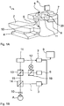
- Fig. 1 shows an ophthalmic laser treatment device 1 for vision correction using laser radiation.
- the treatment device 1 comprises a support device 2 for a patient in the form of a couch and a treatment laser 3 with optics for positioning and focusing the laser beam in the region of a treatment position at which an eye of the patient can be placed. It further comprises a positioning device 4, which carries the couch 2 and can move it linearly in all three spatial directions.
- a microscope beam path is coupled, which allows the practitioner on a viewing eyepiece 6, the visual control of the treatment progress.
- the treatment device 1 comprises a computer ("computer") as a control unit 7 with a keyboard 8 and a monitor as a display 9.
- the ophthalmological device 1 is controlled by the control unit 7.
- the laser 3 is, for example, a femtosecond laser, so that both a flap or a lateral extraction cut and a lenticle can be cut with the same laser.
- the treatment head 5 has, at its end facing the couch 2, a contact element 10 in the form of a contact glass, which touches the eye of the patient during treatment and fixes it spatially relative to the treatment device 1. During the irradiation process, the laser radiation is focused through the contact element 10 into the eye of the patient.
- the contact element 10 may be, for example, plan or anatomically curved on the eye side.
- an excimer laser may be arranged. If only an excimer laser is used, a contact element 10 can be dispensed with. When using an excimer laser, a motion tracking system is useful, which tracks the treatment laser 3 during the irradiation event of any eye movements of the patient.
- FIG. 1B are schematic and greatly simplified in terms of the optical structure of the coupled beam paths of the treatment laser 3, the microscope 6, the detection device 11 and the light source 12 are shown.
- the detection device 11 is designed as a camera, with which the eye A of the patient by two beam splitters 13, 14 and the contact glass 10, which is here still spaced from the eye A, is added.
- an observation beam path 15 extends from the eye A through the contact lens 10 and both beam splitters 13 and 14 to the camera 11.
- the image recorded by means of the camera 11 is transmitted to the computer 7.
- the beam splitter 13 serves to be able to observe the eye A microscopically via the observation eyepiece 6.
- Treatment laser radiation L from the laser 3 to the eye A can be conducted via the beam splitter 14 when the latter is spatially fixed by means of the contact glass 10 in order to carry out the correction of defective vision desired here.
- the light source 12 emits preferably exclusively infrared radiation, since in this case the pupil can open wide and also a high-contrast video recording of the pupil, especially in very dark irises, can be done. However, the light source 12 can also emit additional or alternative visible light. In particular, the visible spectral component can be switched off by means of a filter (not shown). The light of the light source 12 is reflected by a further beam splitter 19, for example in the microscope beam path.
- the video image of the camera 11 is analyzed by the evaluation unit 20. For this purpose, it performs a pupil recognition and displays at least one geometric characteristic, for example, pupil margin, centroid, best fit or best ellipse fit, on the monitor 9 and / or in the eyepiece 6 to the operator in overlay with the video image.
- the evaluation unit 20 performs a pupil recognition and displays at least one geometric characteristic, for example, pupil margin, centroid, best fit or best ellipse fit, on the monitor 9 and / or in the eyepiece 6 to the operator in overlay with the video image.
- a geometric characteristic with at least one treatment parameter, for example the lenticule position, the location and shape of the correction zone of the lenticule, the lenticule diameter, the marginal incision angle, the flap diameter, the flap center, the position of the flap hinge or the angle of the hinge, and / or a system parameter, such as the center of the treatment area, and determines a deviation from a given ideal case and outputs it on the monitor 9.
- a treatment parameter for example the lenticule position, the location and shape of the correction zone of the lenticule, the lenticule diameter, the marginal incision angle, the flap diameter, the flap center, the position of the flap hinge or the angle of the hinge, and / or a system parameter, such as the center of the treatment area
- a degree of overlap between the structure to be generated or at least the refractive corrective portion of the structure and the optical zone and a shift between the center of the pupil as the exemplary reference point and the center point determines the structure to be generated.
- This can be used to control the positioning device 4 so that the couch 2 and thus the eye A of lying on the couch 2 patient can be brought into a predetermined desired position relative to the contact glass 10.
- the displacement may be determined instead of the center of the pupil with any other ophthalmic characteristic by identifying and locating it in the captured image.
- the determination of the shift is on WO 2008/055604 A1 referenced, there in particular Fig. 3 and the related explanations. Expediently, image acquisition and identification as well as localization of the characteristic take place repeatedly in order to be able to take into account changes in the position of the eye. This also applies to the determination of the instantaneous degree of overlap.
- the areas can be determined, for example, by counting picture elements (pixels) in digitized images, for example the intersection pixel, which lies both within the determined pupil edge curve and within the correction zone of the surgical structure.
- the deviation of the centers of gravity of the correction zone and the pupil surface can be used, which permits a statement about the overlap reserve (additional coverage of the correction zone beyond the pupil surface).
- the accuracy of the comparison between treatment parameters and characteristic geometric sizes of the video image can be further improved by additionally adjusting the scaling of the video image and / or the superimposed visualized treatment parameters.
- the scaling ensures a better match of the geometric match of the metric of the coordinate systems to be compared.
- an evaluation of the deviation can take place, in particular from the point of view of whether the current position does not exceed a predetermined threshold value for the decentering and / or does not fall below a predetermined threshold value for the overlap of the optical zone with the structure to be produced.
- the evaluation unit 20 which is for example a software module of the control unit 7, displays, for example, the respectively last recorded image with marking of the recognized characteristic, here the pupil edge, with superposition of the structure to be generated on the monitor 9.
- the structure to be generated and the marking of the recognized characteristic can also be reflected in the microscope beam path, so that the operator perceives these decision aids superimposed directly on the image of the eye A. He can thereby directly perceive the degree of overlap himself.
- an automatic reaction of the device can be initiated, for example a compensation of the detected displacement.
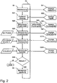
- Fig. 2 the exemplary sequence of a method for motion control in the form of a flow chart is shown schematically.
- the steps are largely the same as in WO 2008/055604 A1 described, wherein the display data in steps S11, S22, S24 and S27 are displayed simultaneously.
- the detected pupil and the determined displacement are superimposed on the video image on the same scale and next to this, the remaining data is superimposed.
- steps S26A, S27A and S28A are performed, which will be explained below.
- the structure to be generated is also superimposed on the video image in the context of the overlap display step S27A.
- the display can take place additionally or alternatively in the eyepiece 6, wherein the video image in the eyepiece 6 is omitted, since the optical image is available there.
- step S26A the instantaneous degree of overlap between the structure S and the current optical zone of the eye A is determined and displayed on the basis of the recognized pupil as geometrical characteristic and the predetermined surgical structure S, for example by hatching the intersection of the surfaces projected into the video image Structure S and the detected pupil P.
- the degree of overlap may be used in the calculation of the correction in step S28 in comparison to a predetermined threshold.
- the threshold describes, for example, an overlap that can be achieved at least. If this can not be achieved by any movement, the procedure is aborted. Otherwise, the determined correction proposal is displayed in step S28A with the other data, for example, as a shift vector in the video image.
- a signal can also be output for the user.
- the signal can be haptic, optical or acoustic.
- a quantitative indication of the extent of the deviation found is provided, in particular a simultaneous video overlay of recognized pupil and expected treatment geometry, for example the lenticular diameter, the flap diameter, or the center points.
- the invention can also be used in excimer laser systems in which the change in shape of the cornea takes place by ablation of the cornea.
- the therapy device usually compensates for minor malpositions by subjecting the beam positioning with a deviation amount measured by motion tracking, but comparing the shape and / or size of the detected pupil in terms of shape and location with the surgical structure provided for execution - an ablation pattern in the excimer laser - can also be used in such treatment methods to improve treatment safety and treatment efficacy. Even then, it is sensible to forego illumination in the visible spectral range and use infrared illumination in order to correctly detect the optical zone effective at night vision of the patient.
- iris structures are used to compare the relative rotational position of the eye with similar information from diagnostic measurements, thus determining relative rotation and relative displacement relative to a diagnostic image (registration image).
- this information is used to perform a rotation and / or displacement of the treatment geometry such that the found relative rotation and / or displacement is compensated for diagnostic measurements.
- the recognized features of the eye are used to verify the identity of the eye to be treated (eye recognition) in comparison with known features of the planned patient's eye.
- the user receives an indication of the probability of error or the measure of identity found.
- Fig. 3 shows two variants of the centering of a lenticle as structure S to be generated, in subfigure 3A near the center of the photopic pupil P, in FIG Partial figure 3B near the center of the scotopic pupil P '. It can be seen that in case A lenticle and scotopic pupil P 'just overlap. The exact evaluation of these or similar situations succeeds the practitioner only in the time available to him, if the inventive solution is available to him.
Description
Die Erfindung betrifft eine ophthalmologische Laser-Behandlungseinrichtung mit einem Behandlungslaser, insbesondere einem Excimerlaser oder einem Femtosekunden-Laser, zum Eintragen von Energie in einen Teil eines Auges eines Patienten gemäß einer vorgegebenen, im Auge zu erzeugenden chirurgischen Struktur, einer Lichtquelle zum Beleuchten zumindest des Teils des Auges und einer Detektionseinrichtung zum Aufnehmen eines Bildes zumindest des Teils des Auges sowie ein Verfahren zum Eintragen von Energie in ein Auge gemäß einer vorgegebenen chirurgischen Struktur mittels eines Excimerlasers oder eines Femtosekunden-Lasers, insbesondere Betriebsverfahren für eine ophthalmologische Laser-Behandlungseinrichtung, die einen Behandlungslaser und eine Detektionseinrichtung zum Aufnehmen eines Bildes des Auges aufweistThe invention relates to an ophthalmic laser treatment device comprising a treatment laser, in particular an excimer laser or a femtosecond laser, for introducing energy into a part of an eye of a patient according to a predetermined surgical structure to be generated in the eye, a light source for illuminating at least the part of the eye and a detection device for taking an image of at least the part of the eye and a method for introducing energy into an eye according to a predetermined surgical structure by means of an excimer laser or a femtosecond laser, in particular operating method for an ophthalmic laser treatment device, the treatment laser and a detection device for capturing an image of the eye
Die chirurgische Struktur kann beispielsweise in Form von Bestrahlungssteuerdatensätzen wie Schussposition, Schussintensität und Schussfrequenz vorgegeben sein. Alternativ kann es sich um abstraktere Angaben wie parametrisierte Raumkurven handeln, die als Vorstufe für Bestrahlungssteuerdaten die zu erzeugenden Schnitte beschreiben. Auch jede andere Form der Darstellung der im Auge zu erzeugenden chirurgischen Struktur ist geeignet. Als Detektionseinrichtung kann beispielsweise eine Digitalkamera verwendet werden.The surgical structure can be predetermined, for example, in the form of radiation control data records such as shot position, shot intensity and firing frequency. Alternatively, it can be more abstract information such as parameterized space curves, which describe the sections to be generated as a precursor for irradiation control data. Any other form of representation of the surgical structure to be created in the eye is also suitable. As a detection device, for example, a digital camera can be used.
Mittels ophthalmologischer Laser-Behandlungseinrichtungen können in der Cornea laserchirurgische Verfahren wie die Femtosekunden-Lentikel-Extraktion (engl. "Femto-second Lenticle Extraction"; FLEx), insbesondere mit kleinen Schnitten (engl. "Small Incision Femto-second Lenticle Extraction"; SMILE), durchgeführt werden. Ein entsprechendes Femtosekunden-Lasersystem ist in
Das Lentikel kann dann mit Hilfe einer Pinzette nach dem Öffnen eines Hornhautlappens (engl "flap"), der das Schnittgebiet überdeckt, oder alternativ durch einen kleinen seitlichen Laser-Schnitt hindurch entnommen werden. Dadurch ist nur ein fs-Lasersystem erforderlich. Alternativ ist es beispielsweise aus
Aus
Es besteht generell die Notwendigkeit, die mittels Excimer- oder Femtosekunden-Laser in das Auge einzutragende Struktur im Koordinatensystem des Lasers exakt zu positionieren. Die erforderliche Genauigkeit ist dabei von der Art der Behandlung abhängig. Erfolgt keine Korrektur von Aberrationen höherer Ordnung als Sphäre und Zylinder, so ist die Genauigkeitsanforderung bei geschickter Gestaltung der chirurgischen Struktur (auch als "Profil" bezeichnet) gering, also etwa 0.2 mm.There is a general need to precisely position the structure to be introduced into the eye by means of an excimer or femtosecond laser in the coordinate system of the laser. The required accuracy depends on the type of treatment. If there is no correction of aberrations of higher order than sphere and cylinder, then the accuracy requirement for a skilful design of the surgical structure (also referred to as a "profile") is low, ie about 0.2 mm.
In
Trotz der Verschiebungskompensation kann es zu einer suboptimalen Behandlung kommen, nach der das Sehvermögen nicht optimal ist, insbesondere in dunklen Umgebungen.Despite the shift compensation, suboptimal treatment may occur, in which vision is not optimal, especially in dark environments.
Der Erfindung liegt die Aufgabe zugrunde, ein ophthalmologische Laser-Behandlungseinrichtung und ein Verfahren der eingangs genannten Art zu verbessern, so dass das Sehvermögen nach einer laserchirurgischen Behandlung verbessert wird.The invention has for its object to improve an ophthalmic laser treatment device and a method of the type mentioned, so that the vision is improved after a laser surgery.
Die Aufgabe wird gelöst durch eine ophthalmologische Laser-Behandlungseinrichtung, welche die in Anspruch 1 angegebenen Merkmale aufweist, und durch ein Verfahren, welches die in Anspruch 8 angegebenen Merkmale aufweist.The object is achieved by an ophthalmic laser treatment device having the features specified in claim 1, and by a method having the features specified in
Vorteilhafte Ausgestaltungen der Erfindung sind in den Unteransprüchen angegeben.Advantageous embodiments of the invention are specified in the subclaims.
Erfindungsgemäß ist eine Auswerteeinheit vorgesehen, die eingerichtet ist zum Ermitteln eines Grades einer momentanen Überlappung einer optischen Zone des Auges und der Struktur oder zumindest eines refraktiv korrigierend wirkenden Teils der Struktur anhand eines aufgenommenen Bildes. Die optische Zone ist im Fall der Behandlung der Cornea die Projektion der (insbesondere maximal geweiteten) Pupillenöffnung auf die Cornea beziehungsweise im allgemeinen Fall generell diejenige Region des zu behandelnden Gewebes, durch die über die (insbesondere maximal geweitete) Pupillenöffnung Licht ins Auge gelangen und zur Bildgebung beitragen kann. Die momentane Überlappung hängt also von der momentanen Öffnungsweite der Pupille ab. Erfindungsgemäß kann darüber hinaus der ermittelte Grad bei mindestens einem der Schritte Ermitteln von Bestrahlungssteuerdaten und Entscheidung über einen Beginn einer Bestrahlung des Auges berücksichtigt werden. Der Grad der Überlappung kann beispielsweise als ein- oder mehrdimensionaler Wert (Skalar, Vektor oder Tensor höherer Stufe) ermittelt werden.According to the invention, an evaluation unit is provided, which is set up for determining a degree of a momentary overlap of an optical zone of the eye and the structure or at least of a refractive corrective-acting part of the structure on the basis of a recorded image. In the case of treatment of the cornea, the optical zone is the projection of the (in particular maximally widened) pupil opening onto the cornea or, in the general case, generally that region of the tissue to be treated, through which light enters the eye via the (in particular maximally widened) pupil opening and Can contribute to imaging. The instantaneous overlap thus depends on the instantaneous opening width of the pupil. According to the invention, moreover, the determined degree in at least one of the steps of determining irradiation control data and Decision on a start of irradiation of the eye should be considered. The degree of overlap can be determined, for example, as a one-dimensional or multi-dimensional value (scalar, vector or tensor of higher level).
Erfindungsgemäß wurde erkannt, dass es unabhängig von der Art der Positionierung (voll- oder halbautomatisch oder manuell) durch die Ermittlung des Grads der Überlappung zwischen (momentaner) optischer Zone und einzutragender Struktur oder zumindest des refraktiv korrigierend wirkenden Teils der Struktur gelingt, die Überdeckung der optischen Zone durch das mittels Laserbearbeitung gezielt veränderte Gewebevolumen zu kontrollieren und so eine vollständige Überdeckung zu ermöglichen, was für eine erfolgreiche refraktive Behandlung ohne Beeinträchtigung des Sehvermögens wichtig ist. Erfolgt - wie im Stand der Technik - keine Kontrolle der Überlappung, so kann bei geringer Umgebungshelligkeit das Sehvermögen beeinträchtigt sein. Erfolgt der Vergleich der Überlappung von Pupillen und Behandlungsgeometrie automatisch, so kann sich der Anwender vollständig auf die Zentrieraufgabe konzentrieren.According to the invention, it has been recognized that regardless of the type of positioning (fully automatic or semi-automatic or manual) by determining the degree of overlap between the (instantaneous) optical zone and the structure to be introduced or at least the refractive corrective part of the structure, the overlap of the The optical zone can be controlled by the tissue volume that has been specifically altered by means of laser processing, thus enabling complete coverage, which is important for a successful refractive treatment without impairing vision. If - as in the prior art - no control of the overlap, so in low ambient brightness, vision may be impaired. If the comparison of the overlapping of the pupils and the treatment geometry is automatic, the user can concentrate completely on the centering task.
Bei der einzutragenden Struktur kann es sich beispielsweise um ein im Anschluss an die Laserbearbeitung manuell zu entfernendes Gewebevolumen (Lentikel) handeln. Es kann sich beispielsweise auch um ein Schnittmuster für die radiale Keratektomie handeln oder um zylindrische oder kegelförmige Schnitte. Meist haben diese Strukturen ein Symmetriezentrum, das etwa im Mittelpunkt der optischen Zone positioniert werden sollte. Solche einzutragenden Strukturen weisen im Zentrum der Struktur oft gerade keine Schnitte auf.The structure to be registered may be, for example, a tissue volume (lenticle) to be removed manually following the laser processing. It may also be, for example, a cutting pattern for the radial keratectomy or cylindrical or conical sections. Most of these structures have a center of symmetry which should be positioned approximately in the center of the optical zone. Such structures to be introduced often do not have any cuts in the center of the structure.
Vorzugsweise ermittelt die Auswerteeinheit zum Ermitteln des Grades der Überlappung eine Fläche der Pupille anhand des aufgenommenen Bildes und eine Fläche der Struktur oder zumindest des refraktiv korrigierend wirkenden Teils der Struktur und eine Schnittmenge der beiden Flächen. Zweckmäßigerweise werden zum Ermitteln der Pupillenfläche Form und Lage der Pupille ermittelt. Die Flächen können beispielsweise als Skalare (Betrag der betreffenden Fläche), als ebene Umrisskurven, als parametrisierte räumliche Vektorflächen oder als Punktwolke diskreter Stützstellen ermittelt werden. Anhand der Schnittmenge kann mit geringem Aufwand der Überlappungsgrad ermittelt werden, beispielsweise durch Ermittlung des Quotienten aus der Flächengröße einer ebenen Projektion der Schnittmenge und der Flächengröße der Pupille. Bei der Bestimmung der Flächen und der Schnittmenge ist notwendigerweise der Abbildungsmaßstab des aufgenommenen Bildes zu berücksichtigen.For determining the degree of overlapping, the evaluation unit preferably determines an area of the pupil on the basis of the recorded image and an area of the structure or at least of the refractive corrective portion of the structure and an intersection of the two areas. Appropriately, the shape and position of the pupil are determined to determine the pupil surface. The areas can be determined, for example, as scalars (amount of the area concerned), as planar contour curves, as parameterized spatial vector areas or as a point cloud of discrete interpolation points. Based on the intersection can be determined with little effort, the degree of overlap, for example by determination the quotient of the area size of a plane projection of the intersection and the area size of the pupil. When determining the areas and the intersection, the magnification of the recorded image must be taken into account.
Vorteilhafterweise ist die Auswerteeinheit eingerichtet zum Identifizieren und Lokalisieren eines Charakteristikums des Auges in dem aufgenommenen Bild und zum Ermitteln einer relativen Verschiebung zwischen einem Punkt des Charakteristikums und einem Punkt der Struktur. Als Charakteristikum kann beispielsweise die Pupille, der Pupillenrand, der Flächenschwerpunkt der Pupille, ein bestangepasster Kreis oder eine bestangepasste Ellipse identifiziert werden. Insbesondere kann eine visuelle und/oder akustische Ausgabe der Verschiebung oder einer entgegengerichtet gleichgroßen Verschiebung und/oder des Grads der Überlappung erfolgen. Die Verschiebung kann vorteilhafterweise bei der Bewertung der Überlappungssituation verwendet werden.Advantageously, the evaluation unit is arranged to identify and locate a characteristic of the eye in the captured image and to determine a relative displacement between a point of the characteristic and a point of the structure. As a characteristic, for example, the pupil, the pupil edge, the centroid of the pupil, a bestangepasterster circle or a best-fitted ellipse can be identified. In particular, a visual and / or acoustic output of the displacement or of an oppositely equal displacement and / or the degree of overlap can take place. The displacement can be advantageously used in the evaluation of the overlap situation.
Um eine ausreichende Überdeckung der optischen Zone durch die chirurgische Struktur (nachfolgend auch als Bearbeitungsgebiet bezeichnet) zu ermöglichen kann die einzutragende Struktur, beispielsweise Randschnitte eines Lentikels, verschoben und/oder vergrößert werden, insbesondere bis eine vollständige Überlappung mit der Pupille prognostiziert wird. Dies kann manuell, halb- oder auch vollautomatisch (durch die Auswerteeinheit oder eine Steuereinheit) erfolgen. Die Vergrößerung des Bearbeitungsgebietes (im Beispiel: die eigentliche Korrekturzone innerhalb des Lentikeldurchmessers) gegenüber der optischen Zone (dem insbesondere maximalen Pupillendurchmesser) um einen Betrag, welcher mindestens der Verschiebung des Bearbeitungszentrums (Lentikelzentrums) gegenüber dem Zentrum der optischen Zone (skotopisches Pupillenzentrum) entspricht, was als Dezentrierung bezeichnet werden kann.In order to allow a sufficient coverage of the optical zone by the surgical structure (hereinafter also referred to as a processing area), the structure to be introduced, for example edge sections of a lenticle, can be displaced and / or enlarged, in particular until a complete overlap with the pupil is predicted. This can be done manually, semi or fully automatically (by the evaluation unit or a control unit). The enlargement of the processing area (in the example: the actual correction zone within the lenticular diameter) with respect to the optical zone (in particular maximum pupil diameter) by an amount which corresponds at least to the displacement of the processing center (lenticule center) with respect to the center of the optical zone (scotopic pupil center), which can be called decentration.
Besonders vorteilhaft ist es daher, wenn die Auswerteeinheit einen Grad der Eignung der momentanen Überdeckungssituation zwischen Struktur und optischer Zone anhand des ermittelten Überlappungsgrades bestimmt und ausgibt. Das erleichtert dem Behandler die Bewertung der Überdeckungssituation und kann so die Behandlungsdauer verkürzen, was die Wahrscheinlichkeit für zwischenzeitige Lageveränderungen durch den Patienten minimiert.It is therefore particularly advantageous if the evaluation unit determines and outputs a degree of suitability of the current coverage situation between structure and optical zone on the basis of the determined degree of overlap. This makes it easier for the practitioner to assess the overlapping situation and so can the Shorten treatment duration, which minimizes the likelihood of patient temporal changes.
Bevorzugt sind Ausführungsformen, in denen die Auswerteeinheit das aufgenommene Bild in Überlagerung mit einer grafischen Darstellung der Struktur gemäß der ermittelten Verschiebung visuell ausgibt. Dadurch kann der Behandler den Grad der Überlagerung und insbesondere die Überdeckungssituation insgesamt besser und schneller interpretieren, was die Behandlungsdauer weiter verkürzt.Embodiments in which the evaluation unit visually outputs the recorded image superimposed on a graphical representation of the structure in accordance with the determined displacement are preferred. As a result, the practitioner can interpret the degree of overlaying and especially the overlapping situation better and faster overall, which further shortens the treatment duration.
Zweckmäßigerweise ist eine Lagerungseinrichtung für den Patienten und eine Positioniereinrichtung zum Verschieben der Lagerungseinrichtung und/oder des Lasers vorgesehen, wobei die Auswerteeinheit die Positioniereinrichtung in Abhängigkeit des ermittelten Grades der Überlappung von Pupille und Struktur und/oder der Verschiebung zwischen Charakteristikum und Struktur steuert. Dadurch kann der Ort, an dem die Struktur erzeugt wird, relativ zum Auge verschoben werden, ohne die zu erzeugende Struktur selbst in sich zu verändern. Im Koordinatensystem des Lasers erfolgt lediglich eine Translation der Struktur. Das ermöglicht die halb- oder vollautomatische Kompensation einer mangelnden Überlappung und kann ebenfalls der Verkürzung der Behandlungsdauer dienen.Appropriately, a storage device for the patient and a positioning device for moving the storage device and / or the laser is provided, wherein the evaluation unit controls the positioning depending on the determined degree of overlap of the pupil and structure and / or the displacement between the characteristic and structure. As a result, the location where the structure is created can be shifted relative to the eye without changing the structure to be created itself. In the coordinate system of the laser, only a translation of the structure takes place. This allows the semi or fully automatic compensation of a lack of overlap and can also serve to shorten the duration of treatment.
Vorteilhaft sind Ausgestaltungen, in denen die Auswerteeinheit einen Wert des ermittelten Grades mit einem vorgegebenen Schwellwert vergleicht und in Abhängigkeit eines Ergebnisses des Vergleichs ein haptisches und/oder visuelles und/oder akustisches Signal ausgibt. So kann beispielsweise der Behandler über eine akzeptable Überdeckung informiert oder vor einer zu geringen Überdeckung gewarnt werden. Alternativ oder zusätzlich kann die Auswerteeinheit einen Wert des ermittelten Grades mit einem vorgegebenen Schwellwert vergleichen und in Abhängigkeit eines Ergebnisses des Vergleichs, insbesondere auch in Abhängigkeit einer relativen Verschiebung zwischen einem Charakteristikum und der Struktur, eine Bestrahlung des Auges gemäß der Struktur durchführt, insbesondere mit Identität der beiden Schwellwerte. Ein solcher Vergleich kann zweckmäßigerweise stattfinden, nachdem eine Verschiebung zwischen Laser und Auge zur Kompensation einer mangelnden Überdeckung durchgeführt wurde. Dies ermöglicht - sofern die Bedingungen für Verschiebung und Überlappung erfüllt sind - insbesondere eine vollautomatische Behandlung, so dass die Wahrscheinlichkeit für zwischenzeitige Lageveränderungen durch den Patienten minimiert wird.Embodiments in which the evaluation unit compares a value of the determined degree with a predetermined threshold value and outputs a haptic and / or visual and / or acoustic signal as a function of a result of the comparison are advantageous. Thus, for example, the practitioner can be informed about an acceptable overlap or be warned against insufficient coverage. Alternatively or additionally, the evaluation unit can compare a value of the determined degree with a predetermined threshold value and, depending on a result of the comparison, in particular also as a function of a relative displacement between a characteristic and the structure, irradiate the eye according to the structure, in particular with identity the two thresholds. Such comparison may conveniently take place after a shift between laser and eye has been made to compensate for a lack of coverage. This allows - in particular, if the conditions for displacement and overlap are met fully automatic treatment, minimizing the likelihood of patient temporal changes.
Vorzugsweise wird das Auge mit Infrarotlicht beleuchtet. Dadurch nimmt die Pupille ihre maximale Öffnungsweite ein, so dass die momentane optische Zone ihre Maximalgröße erreicht. Alternativ kann das Auge zur Aufnahme des Bildes mit sichtbarem Licht beleuchtet werden, wobei eine Intensität des Lichts ermittelt und anhand einer momentanen Fläche des aufgenommenen Bildes und der Intensität eine maximale Pupillenfläche prognostiziert und zum Ermitteln der Überlappung verwendet wird. Die maximale Pupillenweitung kann bei Beleuchtung mit sichtbarem Licht alternativ auch medikamentös erreicht werden, bedeutet aber nach der Behandlung eine vorübergehende Belastung für den Patienten.Preferably, the eye is illuminated with infrared light. As a result, the pupil assumes its maximum opening width, so that the instantaneous optical zone reaches its maximum size. Alternatively, the eye may be illuminated with visible light to capture the image, where an intensity of the light is determined and a maximum pupil area is predicted from a current area of the captured image and intensity and used to determine the overlap. The maximum pupillary dilation can alternatively be achieved by medication in the case of illumination with visible light, but after the treatment means a temporary burden on the patient.
In bevorzugten Ausführungsformen umfasst die ophthalmologische Behandlungseinrichtung ein Kontaktelement zur mechanischen Fixierung des Auges. Das Kontaktelement, typischerweise ein Kontaktglas, ist zweckmäßigerweise transparent für den bei der therapeutischen Bestrahlung verwendeten Spektralbereich. Indem das Auge mechanisch fixiert wird, kann die Gefahr einer falschen Positionierung der chirurgischen Struktur im Auge verringert werden. Die mechanische Fixierung ist insbesondere bei Femtosekunden-Lasern erforderlich.In preferred embodiments, the ophthalmic treatment device comprises a contact element for the mechanical fixation of the eye. The contact element, typically a contact glass, is suitably transparent to the spectral region used in the therapeutic irradiation. By mechanically fixing the eye, the risk of incorrect positioning of the surgical structure in the eye can be reduced. The mechanical fixation is required especially in femtosecond lasers.
Vorteilhafterweise kann das Ermitteln des Grades der momentanen Überlappung vor und/oder nach dem mechanischen Fixieren durchgeführt werden. Die Ermittlung des Überlappungsgrades vor dem Fixieren kann zur Ermittlung einer Verschiebung des Patienten, die notwendig ist, um einen vorgegeben Grad einer Überlappung zu erreichen, dienen. Zu diesem Zweck kann beispielsweise durch eine rechnerische Simulation anhand eines mathematischen Modells ein Grad einer Überlappung in Abhängigkeit einer Verschiebung prognostiziert werden. Anschließend kann beispielsweise diejenige Verschiebung ermittelt werden, für die ein Maximum des Überlappungsgrades prognostiziert wird. Die Verschiebung des Patienten mit anschließender Fixierung des Auges kann dann beispielsweise automatisch durchgeführt werden oder erst nach einer Bestätigung durch den Behandler. Alternativ kann die Verschiebung des Patienten dem Behandler lediglich als Vorschlag ausgegeben werden. Der Behandler muss dann die Fixierung manuell auslösen.Advantageously, the determination of the degree of the instantaneous overlap can be carried out before and / or after the mechanical fixing. Determining the degree of overlap prior to fixation may be used to determine a patient displacement that is necessary to achieve a given degree of overlap. For this purpose, a degree of overlap depending on a displacement can be predicted, for example, by means of a mathematical simulation using a mathematical model. Subsequently, for example, that shift can be determined for which a maximum of the degree of overlap is predicted. The displacement of the patient with subsequent fixation of the eye can then be performed automatically, for example, or only after a confirmation by the practitioner. Alternatively, the displacement of the patient can only be referred to the practitioner as Proposal will be issued. The practitioner must then trigger the fixation manually.
Der Limbus corneae ist als eindeutige Bewegungsverfolgungsreferenz des Auges bezüglich der Hornhaut (Cornea) geeignet. Ist er nicht sichtbar, bleibt nur die Pupille als Hauptgeometriemerkmal. Die Größenveränderlichkeit der Pupille stellt hierbei jedoch einen Nachteil dar. Mit der Größenänderung verschiebt sich auch das Zentrum der Pupille (engl. "pupil center shift"). Daher ist es von Vorteil, während des Andockvorgangs an ein Kontaktelement und/oder danach Bewegungen des Limbus zu verfolgen, da dieser eine feste Beziehung zur Augengeometrie hat. Kennt man insbesondere die Lage des photopischen und des scotopischen Pupillenzentrums in Bezug auf den Limbus, so kann für jeden beliebigen Pupillendurchmesser durch Interpolation die Lage der scotopischen Pupille ermittelt und die Überlappung danach bewertet werden.The limbus corneae is suitable as a clear motion tracking reference of the cornea (cornea) eye. If it is not visible, only the pupil remains as the main geometry feature. However, the size variability of the pupil here represents a disadvantage. With the change in size, the center of the pupil shifts (English "pupil center shift"). Therefore, it is advantageous to track movements of the limbus during the docking operation on a contact element and / or thereafter, since this has a fixed relationship to the eye geometry. In particular, if the position of the photopic and the scotopic pupil center with respect to the limbus is known, then the position of the scotopic pupil can be determined for each pupil diameter by interpolation and the overlap can then be evaluated.
Die Erfindung umfasst auch eine Steuereinheit, die zur Durchführung eines erfindungsgemäßen Verfahrens eingerichtet ist. Die Einrichtung kann programmtechnisch vorliegen, beispielsweise durch Softwaremodule zum Ermitteln eines Grades einer momentanen Überlappung einer optischen Zone des Auges und der Struktur anhand des aufgenommenen Bildes und zum Ermitteln von Bestrahlungssteuerdaten und/oder zur Entscheidung über einen Beginn einer Bestrahlung des Auges in Abhängigkeit des ermittelten Grades.The invention also includes a control unit which is set up to carry out a method according to the invention. The device can be present in the program, for example by software modules for determining a degree of instantaneous overlapping of an optical zone of the eye and the structure on the basis of the recorded image and for determining irradiation control data and / or for deciding on a start of irradiation of the eye as a function of the determined degree ,
Die Erfindung ist nicht nur zur Anwendung an der Cornea vorgesehen, sondern kann an allen Teilen des Vorderauges angewendet werden, beispielsweise an der Augenlinse oder dem Kapselsack.The invention is not only intended for use on the cornea, but can be applied to all parts of the fore-eye, for example to the eye lens or the capsular bag.
Nachfolgend wird die Erfindung anhand von Ausführungsbeispielen näher erläutert.The invention will be explained in more detail by means of exemplary embodiments.
In den Zeichnungen zeigen:
-
Fig. 1 eine ophthalmologische Laser-Behandlungseinrichtung, -
Fig. 2 ein Flussdiagramm eines Verfahrens zur Steuerung einer Kompensationsbewegung und -
Fig. 3 Varianten der Zentrierung eines Lentikels.
-
Fig. 1 an ophthalmic laser treatment device, -
Fig. 2 a flowchart of a method for controlling a compensation movement and -
Fig. 3 Variants of centering a lenticle.
In allen Zeichnungen tragen übereinstimmende Teile gleiche Bezugszeichen.In all drawings, like parts bear like reference numerals.
Ferner umfasst die Behandlungseinrichtung 1 einen Rechner (engl. "computer") als Steuereinheit 7 mit einer Tastatur 8 und einem Monitor als Anzeige 9. Die ophthalmologische Einrichtung 1 wird mittels der Steuereinheit 7 gesteuert. Der Laser 3 ist beispielsweise ein Femtosekunden-Laser, so dass sowohl ein Flap oder ein seitlicher Entnahmeschnitt als auch ein Lentikel mit demselben Laser geschnitten werden können. Der Behandlungskopf 5 weist an seinem der Liege 2 zugewandten Ende ein Kontaktelement 10 in Form eines Kontaktglases auf, das während der Behandlung das Auge des Patienten berührt und relativ zur Behandlungseinrichtung 1 räumlich fixiert. Während des Bestrahlungsvorgangs wird die Laserstrahlung durch das Kontaktelement 10 hindurch in das Auge des Patienten fokussiert. Das Kontaktelement 10 kann augenseitig beispielsweise plan oder anatomisch gekrümmt sein.Furthermore, the treatment device 1 comprises a computer ("computer") as a
In alternativen Ausführungsformen kann anstelle des oder zusätzlich zu dem Femtosekunden-Lasers ein Excimerlaser angeordnet sein. Sofern ausschließlich ein Excimerlaser verwendet wird, kann auf ein Kontaktelement 10 verzichtet werden. Beim Einsatz eines Excimerlasers ist ein Bewegungsverfolgungssystem zweckmäßig, das den Behandlungslaser 3 während des Bestrahlungsvorgangs eventuellen Augenbewegungen des Patienten nachführt.In alternative embodiments, instead of or in addition to the femtosecond laser, an excimer laser may be arranged. If only an excimer laser is used, a
In Teilfig. 1B sind schematisch und hinsichtlich des optischen Aufbaus stark vereinfacht die gekoppelten Strahlengänge des Behandlungslasers 3, des Mikroskops 6, der Detektionseinrichtung 11 sowie der Lichtquelle 12 dargestellt. Die Detektionseinrichtung 11 ist als Kamera ausgebildet, mit der das Auge A des Patienten durch zwei Strahlteiler 13, 14 und das Kontaktglas 10, das hier vom Auge A noch beabstandet ist, aufgenommen wird. Es verläuft somit ein Beobachtungsstrahlengang 15 vom Auge A durch das Kontaktglas 10 und beide Strahlteiler 13 und 14 bis zur Kamera 11. Das mittels der Kamera 11 aufgenommene Bild wird zum Computer 7 übertragen. Der Strahlteiler 13 dient dazu, über das Beobachtungsokular 6 das Auge A mikroskopisch beobachten zu können. Über den Strahlteiler 14 kann Behandlungs-Laserstrahlung L vom Laser 3 zum Auge A geleitet werden, wenn dieses mittels des Kontaktglases 10 räumlich fixiert ist, um die hier gewünschte Fehlsichtigkeitskorrektur durchzuführen.In partfig. 1B are schematic and greatly simplified in terms of the optical structure of the coupled beam paths of the
Die Lichtquelle 12 emittiert vorzugsweise ausschließlich Infrarotstrahlung, da sich in diesem Fall die Pupille weit öffnen kann und zudem eine kontraststarke Videoaufnahme der Pupille, insbesondere auch bei sehr dunkler Iris, erfolgen kann. Die Lichtquelle 12 kann aber auch zusätzlich oder alternativ sichtbares Licht emittieren. Insbesondere kann der sichtbare Spektralanteil mittels eines Filters (nicht abgebildet) abschaltbar sein. Das Licht der Lichtquelle 12 wird über einen weiteren Strahlteiler 19 beispielsweise in den Mikroskopstrahlengang eingespiegelt.The
Wenn das Auge des Patienten durch die Einrichtung 7 erfasst wird, vorzugsweise während des Andockvorgangs an das Kontaktelement 10 oder unmittelbar danach, wird durch die Auswerteeinheit 20 das Videobild der Kamera 11 analysiert. Zu diesem Zweck führt sie eine Pupillenerkennung durch und zeigt zumindest ein geometrisches Charakteristikum, beispielsweise Pupillenrand, Flächenschwerpunkt, beste Kreisanpassung (engl. "fit") oder beste Ellipsenanpassung, auf dem Monitor 9 und/oder im Okular 6 dem Bediener in Überlagerung mit dem Videobild an. Zusätzlich oder alternativ vergleicht sie ein geometrisches Charakteristikum mit mindestens einem Behandlungsparameter, beispielsweise der Lentikelposition, der Lage und Form der Korrekturzone des Lentikels, dem Lentikeldurchmesser, dem Randschnittwinkel, dem Flapdurchmesser, der Flapmitte, der Position des Flapscharniers (engl. "hinge") oder dem Winkel des Scharniers, und/oder einem Systemparameter, beispielsweise dem Mittelpunkt des Behandlungsgebiets, und bestimmt eine Abweichung von einem vorgegebenen Idealfall und gibt sie auf dem Monitor 9 aus.If the eye of the patient is detected by the
Beispielsweise werden bei der Analyse mittels Bestimmung des Flächenverhältnisses von Pupille und entsprechend skalierter chirurgischer Struktur ein Grad der Überlappung zwischen zu erzeugender Struktur oder zumindest dem refraktiv korrigierend wirkenden Teil der Struktur und optischer Zone sowie eine Verschiebung zwischen dem Mittelpunkt der Pupille als beispielhaftem Referenzpunkt und dem Mittelpunkt der zu erzeugenden Struktur ermittelt. Diese kann dazu verwendet werden, die Positioniereinrichtung 4 so anzusteuern, dass die Liege 2 und somit das Auge A des auf der Liege 2 liegenden Patienten in eine vorbestimmte Soll-Position relativ zum Kontaktglas 10 gebracht werden kann. Die Verschiebung kann anstelle der Pupillenmitte alternativ mit jedem anderen augenfesten Charakteristikum ermittelt werden, indem diese in dem aufgenommenen Bild identifiziert und lokalisiert wird. Zur Beschreibung der Ermittlung der Verschiebung wird auf
Die Flächen können beispielsweise durch Zählen von Bildelementen (engl. "picture elements", pixels) in digitalisierten Bildern ermittelt werden, beispielsweise der Schnittmengenpixel, die sowohl innerhalb ermittelten Pupillenrandkurve als auch innerhalb der Korrekturzone der chirurgischen Struktur liegt. Das Verhältnis der Flächeninhalte der gesamten Pupillenfläche mit dem Anteil der Pupillenfläche, welcher mit der Korrekturzone zusammenfällt, ergibt den Überlappungsgrad. Dieser beträgt gerade dann 100%, wenn die Pupille sich vollständig in der Korrekturzone befindet. Zum Grad der Eignung kann weiterhin die Abweichung der Schwerpunkte von Korrekturzone und Pupillenfläche herangezogen werden, welche eine Aussage über die Überlappungsreserve (zusätzliche Überdeckung der Korrekturzone über die Pupillenfläche hinaus) erlaubt. Es ist aber auch denkbar, bei bereits partieller Überlappung von beispielsweise nur 90% oder 95% ein Signal für eine ausreichende Eignung auszugeben.The areas can be determined, for example, by counting picture elements (pixels) in digitized images, for example the intersection pixel, which lies both within the determined pupil edge curve and within the correction zone of the surgical structure. The ratio of the area of the entire pupil surface to the proportion of the pupil surface, which coincides with the correction zone, gives the degree of overlap. This is just 100% when the pupil is completely in the correction zone. In addition to the degree of suitability, the deviation of the centers of gravity of the correction zone and the pupil surface can be used, which permits a statement about the overlap reserve (additional coverage of the correction zone beyond the pupil surface). However, it is also conceivable to output a signal for sufficient suitability if there is already partial overlap of, for example, only 90% or 95%.
Die Genauigkeit des Vergleichs zwischen Behandlungsparametern und charakteristischen geometrischen Größen des Videobildes kann durch eine zusätzliche Anpassung der Skalierung des Videobildes und/oder der überlagerten visualisierten Behandlungsparameter weiter verbessert werden. Die Skalierung sorgt dabei für eine bessere Übereinstimmung geometrische Übereinstimmung der Metrik der zu vergleichenden Koordinatensysteme. Zudem kann eine Bewertung der Abweichung erfolgen, insbesondere unter dem Gesichtspunkt, ob die aktuelle Position einen vorgegebenen Schwellwert für die Dezentrierung nicht überschreitet und/oder einen vorgegebenen Schwellwert für die Überlappung der optischen Zone mit der zu erzeugenden Struktur nicht unterschreitet.The accuracy of the comparison between treatment parameters and characteristic geometric sizes of the video image can be further improved by additionally adjusting the scaling of the video image and / or the superimposed visualized treatment parameters. The scaling ensures a better match of the geometric match of the metric of the coordinate systems to be compared. In addition, an evaluation of the deviation can take place, in particular from the point of view of whether the current position does not exceed a predetermined threshold value for the decentering and / or does not fall below a predetermined threshold value for the overlap of the optical zone with the structure to be produced.
Die Auswerteeinheit 20, die beispielsweise ein Softwaremodul der Steuereinheit 7 ist, zeigt beispielsweise das jeweils zuletzt aufgenommene Bild unter Markierung des erkannten Charakteristikums, hier des Pupillenrandes, mit Überlagerung der zu erzeugenden Struktur auf dem Monitor 9 an. Wahlweise kann die zu erzeugende Struktur und die Markierung des erkannten Charakteristikums auch in den Mikroskopstrahlengang eingespiegelt werden, so dass der Bediener diese Entscheidungshilfen direkt mit dem Bild des Auges A überlagert wahrnimmt. Er kann dadurch den Grad der Überlappung unmittelbar selbst wahrnehmen.The
In einer speziellen Ausführung kann basierend auf der Bewertung kann eine automatische Reaktion des Gerätes eingeleitet werden, beispielsweise eine Kompensation der detektierten Verschiebung.In a specific embodiment, based on the evaluation, an automatic reaction of the device can be initiated, for example a compensation of the detected displacement.
In
In Schritt S26A wird anhand der erkannten Pupille als geometrischem Charakteristikum und der vorgegebenen chirurgischen Struktur S der momentane Grad der Überlappung zwischen der Struktur S und der momentanen optischen Zone des Auges A ermittelt und angezeigt, beispielsweise durch Schraffur der Schnittmenge der in das Videobild projizierten Flächen der Struktur S und der erkannten Pupille P. Der Grad der Überlappung kann in der Berechnung der Korrektur in Schritt S28 im Vergleich zu einem vorgegebenen Schwellwert verwendet werden. Der Schwellwert beschreibt beispielsweise eine mindestens zu erreichende Überlappung. Kann diese durch keine Bewegung erreicht werden, wird das Verfahren abgebrochen. Der ermittelte Korrekturvorschlag wird anderenfalls in Schritt S28A mit den anderen Daten angezeigt, beispielsweise als Verschiebungsvektor im Videobild.In step S26A, the instantaneous degree of overlap between the structure S and the current optical zone of the eye A is determined and displayed on the basis of the recognized pupil as geometrical characteristic and the predetermined surgical structure S, for example by hatching the intersection of the surfaces projected into the video image Structure S and the detected pupil P. The degree of overlap may be used in the calculation of the correction in step S28 in comparison to a predetermined threshold. The threshold describes, for example, an overlap that can be achieved at least. If this can not be achieved by any movement, the procedure is aborted. Otherwise, the determined correction proposal is displayed in step S28A with the other data, for example, as a shift vector in the video image.
Alternativ zu einer vollautomatischen Kompensationsbewegung kann auch ein Signal für den Anwender ausgegeben werden. Das Signal kann haptischer, optischer oder akustischer Art sein. Insbesondere ist eine quantitative Angabe über das Maß der gefundenen Abweichung vorgesehen, insbesondere eine gleichzeitige Videoüberlagerung von erkannter Pupille und erwarteter Behandlungsgeometrie, beispielsweise dem Lentikeldurchmesser, dem Flapdurchmesser, oder den Mittelpunkten.As an alternative to a fully automatic compensation movement, a signal can also be output for the user. The signal can be haptic, optical or acoustic. In particular, a quantitative indication of the extent of the deviation found is provided, in particular a simultaneous video overlay of recognized pupil and expected treatment geometry, for example the lenticular diameter, the flap diameter, or the center points.
Die Erfindung kann auch bei Excimer-Lasersystemen eingesetzt werden, bei denen die Formveränderung der Hornhaut durch Ablation der Cornea erfolgt. Zwar besteht dort nicht die Aufgabe, den Patienten bezüglich der Therapieoptik mit hoher Genauigkeit zu positionieren, da das Therapiegerät üblicherweise mittels Beaufschlagung der Strahlpositionierung mit einem durch Bewegungsverfolgung gemessenen Abweichungsbetrag kleinere Fehlpositionierungen ausgleicht, doch der Vergleich der Form und/oder Größe der detektierten Pupille hinsichtlich Form und Lage mit dem zur Ausführung vorgesehenen chirurgischen Struktur - beim Excimerlaser ein Ablationsmuster (engl. "ablation pattern") - kann auch bei solchen Behandlungsverfahren zur Verbesserung der Behandlungssicherheit und Behandlungswirksamkeit eingesetzt werden. Auch dann ist der Verzicht auf Beleuchtung im sichtbaren Spektralbereich und Anwendung infraroter Beleuchtung sinnvoll, um die bei Nachtsicht des Patienten wirksame optische Zone korrekt zu erfassen.The invention can also be used in excimer laser systems in which the change in shape of the cornea takes place by ablation of the cornea. Although there is not the task to position the patient with high accuracy with respect to the therapy optics, since the therapy device usually compensates for minor malpositions by subjecting the beam positioning with a deviation amount measured by motion tracking, but comparing the shape and / or size of the detected pupil in terms of shape and location with the surgical structure provided for execution - an ablation pattern in the excimer laser - can also be used in such treatment methods to improve treatment safety and treatment efficacy. Even then, it is sensible to forego illumination in the visible spectral range and use infrared illumination in order to correctly detect the optical zone effective at night vision of the patient.
In einer weiteren Ausgestaltung werden auch andere Merkmale des Auges erkannt, beispielsweise Irisstrukturen. Diese werden dazu verwendet, die relative Drehlage des Auges mit gleichartiger Information aus Diagnosemessungen zu vergleichen, um auf diese Weise relative Verdrehung und relative Verschiebung bezüglich einer Diagnoseaufnahme (Registrierbild) zu bestimmen.In a further embodiment, other features of the eye are recognized, such as iris structures. These are used to compare the relative rotational position of the eye with similar information from diagnostic measurements, thus determining relative rotation and relative displacement relative to a diagnostic image (registration image).
In einer weiteren Ausgestaltung wird diese Information dazu verwendet, um eine Drehung und/oder Verschiebung der Behandlungsgeometrie derart durchzuführen, dass die gefundene relative Verdrehung und/oder Verschiebung gegenüber Diagnosemessungen kompensiert wird.In a further embodiment, this information is used to perform a rotation and / or displacement of the treatment geometry such that the found relative rotation and / or displacement is compensated for diagnostic measurements.
In einer weiteren Ausgestaltung werden die erkannten Merkmale des Auges dazu verwendet, im Vergleich mit bekannten Merkmalen des geplanten Patientenauges die Identität des zu behandelnden Auges zu überprüfen (Augenerkennung). In diesem Fall erhält der Anwender eine Angabe über die Irrtumswahrscheinlichkeit oder das gefundene Maß der Identität.In a further embodiment, the recognized features of the eye are used to verify the identity of the eye to be treated (eye recognition) in comparison with known features of the planned patient's eye. In this case, the user receives an indication of the probability of error or the measure of identity found.
Zur Beschreibung der Erzeugung der Laserstrahlung wird auf
- 11
- Laser-BehandlungseinrichtungLaser treatment facility
- 22
- Lagerungseinrichtungstorage facility
- 33
- Behandlungslaserlaser treatment
- 44
- Positioniereinrichtungpositioning
- 55
- Behandlungskopftreatment head
- 66
- Beobachtungsokularobservation eyepiece
- 77
- Steuereinheitcontrol unit
- 88th
- Tastaturkeyboard
- 99
- Monitormonitor
- 1010
- Kontaktelementcontact element
- 1111
- Detektionseinrichtungdetection device
- 1212
- Lichtquellelight source
- 1313
- Strahlteilerbeamsplitter
- 1414
- Strahlteilerbeamsplitter
- 1515
- BeobachtungsstrahlengangObservation beam path
- 1919
- Strahlteilerbeamsplitter
- 2020
- Auswerteeinheitevaluation
- AA
- Augeeye
- BB
- Videobildvideo image
- PP
- Pupillepupil
- SS
- Chirurgische StrukturSurgical structure
Claims (9)
- Ophthalmological laser treatment device (1), having- a treatment laser (3), in particular an excimer laser or femtosecond laser, for introducing energy into a part of an eye (A) of a patient according to a predetermined surgical structure (S),- a light source (5) for illuminating at least the part of the eye (A) and- a detection device (6) for recording an image (B) of at least the part of the eye (A),characterized by an evaluation unit (20) that is configured to ascertain a degree of a current overlap of an optical zone (P) of the eye (A) and the structure (S) or at least a part of the structure (S) with a refractively correcting effect on the basis of a recorded image (B).
- Ophthalmological treatment device (1) according to Claim 1, wherein the evaluation unit (20) for ascertaining the degree of overlap ascertains an area of the pupil (P) on the basis of the recorded image (B) and an area of the structure (S) or at least of the part of the structure (S) with a refractively correcting effect and an intersection of the two areas.
- Ophthalmological treatment device (1) according to Claim 1 or 2, wherein the evaluation unit (20) is configured to identify and localize a characteristic of the eye (A), in particular of a pupil (P), in the recorded image and to ascertain a relative displacement between a point of the characteristic and a point of the structure (S).
- Ophthalmological treatment device (1) according to the preceding claim, wherein the evaluation unit (20) visually outputs the recorded image (B) in a superposition with a graphical illustration of the structure (S) according to the ascertained displacement.
- Ophthalmological treatment device (1) according to Claim 2 and/or Claim 3, further comprising a bearing device (2) for the patient and a positioning device (4) for displacing the bearing device (2) and/or the laser (3), wherein the evaluation unit (20) controls the positioning unit (4) depending on the ascertained degree of overlap between the pupil (P) and structure (S) and/or the displacement between the characteristic and structure (S).
- Ophthalmological treatment device (1) according to any one of the preceding claims, wherein the evaluation unit (20) compares a value of the ascertained degree to a predetermined threshold value and, depending on a result of the comparison, outputs a haptic and/or visual and/or acoustic signal and/or wherein the evaluation unit (20) compares a value of the ascertained degree to a predetermined threshold value and, depending on a result of the comparison, in particular also depending on a relative displacement, carries out an irradiation of the eye (A) according to the structure (S), in particular with the two threshold values being identical.
- Ophthalmological treatment device (1) according to any one of the preceding claims, comprising a contact element (10) for mechanically fixing the eye (A).
- Ophthalmological treatment device (1) according to the preceding claim, wherein the evaluation unit (20) is configured to carry out the ascertainment of the degree of the current overlap before and/or after the mechanical fixing.
- Apparatus according to any one of the preceding claims, wherein the surgical structure has a centre of symmetry that is freed from places to be irradiated.
Applications Claiming Priority (2)
| Application Number | Priority Date | Filing Date | Title |
|---|---|---|---|
| DE102010012616A DE102010012616A1 (en) | 2010-03-20 | 2010-03-20 | Ophthalmic laser treatment device and method of operation for such |
| PCT/EP2011/001319 WO2011116900A1 (en) | 2010-03-20 | 2011-03-17 | Ophthalmological laser treatment device |
Publications (2)
| Publication Number | Publication Date |
|---|---|
| EP2549964A1 EP2549964A1 (en) | 2013-01-30 |
| EP2549964B1 true EP2549964B1 (en) | 2018-08-15 |
Family
ID=44169115
Family Applications (1)
| Application Number | Title | Priority Date | Filing Date |
|---|---|---|---|
| EP11712169.9A Active EP2549964B1 (en) | 2010-03-20 | 2011-03-17 | Ophthalmological laser treatment device |
Country Status (4)
| Country | Link |
|---|---|
| US (2) | US8858540B2 (en) |
| EP (1) | EP2549964B1 (en) |
| DE (1) | DE102010012616A1 (en) |
| WO (1) | WO2011116900A1 (en) |
Families Citing this family (11)
| Publication number | Priority date | Publication date | Assignee | Title |
|---|---|---|---|---|
| WO2011139605A2 (en) * | 2010-04-27 | 2011-11-10 | Haddad Daniel S | Dynamic real time active pupil centroid compensation |
| DE102011083928A1 (en) * | 2011-09-30 | 2013-04-04 | Carl Zeiss Meditec Ag | A treatment device for operative vision correction of an eye, a method for generating control data therefor and methods for surgical correction of defective vision of an eye |
| DE102015002729A1 (en) * | 2015-02-27 | 2016-09-01 | Carl Zeiss Meditec Ag | Ophthalmic laser therapy device and method for generating corneal access incisions |
| NZ773833A (en) | 2015-03-16 | 2022-07-01 | Magic Leap Inc | Methods and systems for diagnosing and treating health ailments |
| IL299497B2 (en) | 2016-04-08 | 2024-02-01 | Magic Leap Inc | Augmented reality systems and methods with variable focus lens elements |
| AU2018225146A1 (en) | 2017-02-23 | 2019-08-29 | Magic Leap, Inc. | Display system with variable power reflector |
| DE102019213869A1 (en) * | 2018-09-20 | 2020-03-26 | Carl Zeiss Meditec Ag | Creation of cuts inside the eye |
| CN110200585B (en) * | 2019-07-03 | 2022-04-12 | 南京博视医疗科技有限公司 | Laser beam control system and method based on fundus imaging technology |
| DE102019121731A1 (en) * | 2019-08-13 | 2021-02-18 | Carl Zeiss Meditec Ag | Method for monitoring a functionality of a device for refractive surgery of an eye, control unit and device for refractive surgery of an eye |
| DE102019213735A1 (en) * | 2019-09-10 | 2021-03-11 | Carl Zeiss Meditec Ag | Ophthalmic surgical treatment device |
| DE102020110041A1 (en) * | 2020-04-09 | 2021-10-14 | Precitec Optronik Gmbh | Method for determining the position of a flap incision on a cornea and the limb belonging to the flap and a device for carrying out such a method |
Citations (3)
| Publication number | Priority date | Publication date | Assignee | Title |
|---|---|---|---|---|
| WO1999044492A1 (en) * | 1998-03-04 | 1999-09-10 | Visx, Incorporated | Method and systems for laser treatment of presbyopia using offset imaging |
| US20020049431A1 (en) * | 2000-10-20 | 2002-04-25 | Smith Michael J. | Method of correcting corneal refraction not aligned with the pupil center |
| US20030120266A1 (en) * | 2001-12-03 | 2003-06-26 | Masanao Fujieda | Ophthalmic apparatus and corneal surgery apparatus |
Family Cites Families (21)
| Publication number | Priority date | Publication date | Assignee | Title |
|---|---|---|---|---|
| US6267756B1 (en) * | 1986-03-08 | 2001-07-31 | G. Rodenstock Instrumente Gmbh | Apparatus for the observation and the treatment of the eye using a laser |
| US5620436A (en) * | 1994-09-22 | 1997-04-15 | Chiron Technolas Gmbh Ophthalmologische Systeme | Method and apparatus for providing precise location of points on the eye |
| US7892226B2 (en) | 1995-03-20 | 2011-02-22 | Amo Development, Llc. | Method of corneal surgery by laser incising a contoured corneal flap |
| US5801807A (en) * | 1995-08-08 | 1998-09-01 | Nikon Corporation | Ophthalmic illumination device having adjustable transmittance member and microscope for operation using the same |
| US6159202A (en) * | 1995-09-29 | 2000-12-12 | Nidex Co., Ltd. | Corneal surgery apparatus |
| ES2199095T3 (en) * | 1999-10-21 | 2007-03-16 | Technolas Gmbh Ophthalmologische Systeme | IRIS RECOGNITION AND FOLLOW-UP FOR OPTICAL TREATMENT. |
| US7044602B2 (en) * | 2002-05-30 | 2006-05-16 | Visx, Incorporated | Methods and systems for tracking a torsional orientation and position of an eye |
| US6899707B2 (en) * | 2001-01-29 | 2005-05-31 | Intralase Corp. | Applanation lens and method for ophthalmic surgical applications |
| US20050117118A1 (en) * | 2001-10-05 | 2005-06-02 | David Miller | Digital ophthalmic workstation |
| JP3916482B2 (en) | 2002-02-27 | 2007-05-16 | 株式会社ニデック | Ophthalmic equipment |
| US8052674B2 (en) * | 2004-04-09 | 2011-11-08 | Roger F. Steinert | Laser system for vision correction |
| US7780653B2 (en) * | 2004-09-20 | 2010-08-24 | Hovanesian John A | Methods and apparatus for vision correction |
| US7662148B2 (en) | 2004-11-12 | 2010-02-16 | Technolas Perfect Vision Gmbh | Systems and methods for intrastromal scanning patterns |
| US7815631B2 (en) * | 2004-11-30 | 2010-10-19 | Alcon Refractivehorizons, Inc. | Eye registration system for refractive surgery and associated methods |
| DE102006053098A1 (en) | 2006-11-10 | 2008-05-15 | Carl Zeiss Meditec Ag | Ophthalmological device for contacting therapy process i.e. femto-second Laser treatment, has detection device holding eye of patient on suspension device and determining indication about relative shift of suspension device |
| DE102006056711B4 (en) | 2006-11-30 | 2019-09-19 | Carl Zeiss Meditec Ag | Device for generating a correction interface in the cornea of an eye for correction of defective vision and contact element for such a device |
| JP5220033B2 (en) * | 2007-02-14 | 2013-06-26 | ツィーマ ホールディング アクチェンゲゼルシャフト | Ophthalmic device for disassembling eye tissue |
| DE102007060008A1 (en) * | 2007-12-13 | 2009-06-18 | Technolas Gmbh Ophthalmologische Systeme | Determination and monitoring of laser energy |
| DE102007055924B4 (en) * | 2007-12-21 | 2009-11-26 | Carl Zeiss Surgical Gmbh | Method for determining characteristic properties and / or the position of characteristic ocular components |
| US8444632B2 (en) * | 2008-11-05 | 2013-05-21 | Carl Zeiss Meditec Ag | Method of performing refractive laser eye surgery centered along the visual axis of a human eye |
| US9492322B2 (en) * | 2009-11-16 | 2016-11-15 | Alcon Lensx, Inc. | Imaging surgical target tissue by nonlinear scanning |
-
2010
- 2010-03-20 DE DE102010012616A patent/DE102010012616A1/en active Pending
-
2011
- 2011-03-17 EP EP11712169.9A patent/EP2549964B1/en active Active
- 2011-03-17 US US13/635,999 patent/US8858540B2/en active Active
- 2011-03-17 WO PCT/EP2011/001319 patent/WO2011116900A1/en active Application Filing
-
2014
- 2014-09-11 US US14/483,515 patent/US20150005752A1/en not_active Abandoned
Patent Citations (3)
| Publication number | Priority date | Publication date | Assignee | Title |
|---|---|---|---|---|
| WO1999044492A1 (en) * | 1998-03-04 | 1999-09-10 | Visx, Incorporated | Method and systems for laser treatment of presbyopia using offset imaging |
| US20020049431A1 (en) * | 2000-10-20 | 2002-04-25 | Smith Michael J. | Method of correcting corneal refraction not aligned with the pupil center |
| US20030120266A1 (en) * | 2001-12-03 | 2003-06-26 | Masanao Fujieda | Ophthalmic apparatus and corneal surgery apparatus |
Also Published As
| Publication number | Publication date |
|---|---|
| WO2011116900A1 (en) | 2011-09-29 |
| US20130072916A1 (en) | 2013-03-21 |
| US8858540B2 (en) | 2014-10-14 |
| US20150005752A1 (en) | 2015-01-01 |
| DE102010012616A1 (en) | 2011-09-22 |
| EP2549964A1 (en) | 2013-01-30 |
Similar Documents
| Publication | Publication Date | Title |
|---|---|---|
| EP2549964B1 (en) | Ophthalmological laser treatment device | |
| EP2729099B1 (en) | Device and method for a laser-assisted eye surgery treatment system | |
| EP2337534B1 (en) | Device, method and control program for ophthalmologic, particularly refractive, laser surgery | |
| EP1404265B9 (en) | Device for representing an operative field during laser operations | |
| EP1985269B1 (en) | Device, method and control program for refractive surgery | |
| EP2306949B1 (en) | Device for ophthalmologic, particularly refractive, laser surgery | |
| DE112011103923B4 (en) | Method and device for multistage eye registration | |
| EP2042078A2 (en) | Method for determining distances from the front eye section | |
| EP3010390B1 (en) | System for detecting position data of at least one element in the front region of an eye | |
| DE102013105738A1 (en) | Laser treatment device for refractive surgery | |
| WO2021069220A1 (en) | Arrangement for the oct-based laser vitreolysis | |
| DE102006053098A1 (en) | Ophthalmological device for contacting therapy process i.e. femto-second Laser treatment, has detection device holding eye of patient on suspension device and determining indication about relative shift of suspension device | |
| EP4027957A1 (en) | Positioning device | |
| DE102004030904A1 (en) | Device for detecting the spatial position of the optical axis of an eye and for centering a reference system relative to the optical axis | |
| EP4225236A1 (en) | Method for centring a contact lens and refractive surgical laser system | |
| EP1200026B1 (en) | Device for ophthalmologically treating the eye using a fixation light beam | |
| WO2022063961A1 (en) | Assembly for laser treatment of ocular opacities | |
| DE102007055919B4 (en) | Eye viewing system and method therefor | |
| DE102009030464B4 (en) | Laser device and method, in particular operating method for a laser device, for creating irradiation control data for a pulsed laser | |
| DE102019219123A1 (en) | Observation device | |
| DE102022121079A1 (en) | REFRACTIVE SURGICAL LASER SYSTEM AND METHOD FOR DETERMINING A DISTANCE BETWEEN A CONTACT LENS AND A PATIENT'S EYE | |
| DE102019213734A1 (en) | Ophthalmic surgical treatment device | |
| DE102015217849A1 (en) | Systems and methods for laser-assisted eye treatment | |
| DE102011075734A1 (en) | Laser therapy device for treatment of human eye, particularly for surgery of cornea, sclera, vitreous humor or eye lens, has inlet device for introducing portion of beam guide medium along with optical outlet unit in treatment area |
Legal Events
| Date | Code | Title | Description |
|---|---|---|---|
| PUAI | Public reference made under article 153(3) epc to a published international application that has entered the european phase |
Free format text: ORIGINAL CODE: 0009012 |
|
| 17P | Request for examination filed |
Effective date: 20121018 |
|
| AK | Designated contracting states |
Kind code of ref document: A1 Designated state(s): AL AT BE BG CH CY CZ DE DK EE ES FI FR GB GR HR HU IE IS IT LI LT LU LV MC MK MT NL NO PL PT RO RS SE SI SK SM TR |
|
| DAX | Request for extension of the european patent (deleted) | ||
| GRAP | Despatch of communication of intention to grant a patent |
Free format text: ORIGINAL CODE: EPIDOSNIGR1 |
|
| STAA | Information on the status of an ep patent application or granted ep patent |
Free format text: STATUS: GRANT OF PATENT IS INTENDED |
|
| INTG | Intention to grant announced |
Effective date: 20170927 |
|
| GRAJ | Information related to disapproval of communication of intention to grant by the applicant or resumption of examination proceedings by the epo deleted |
Free format text: ORIGINAL CODE: EPIDOSDIGR1 |
|
| STAA | Information on the status of an ep patent application or granted ep patent |
Free format text: STATUS: REQUEST FOR EXAMINATION WAS MADE |
|
| GRAP | Despatch of communication of intention to grant a patent |
Free format text: ORIGINAL CODE: EPIDOSNIGR1 |
|
| STAA | Information on the status of an ep patent application or granted ep patent |
Free format text: STATUS: GRANT OF PATENT IS INTENDED |
|
| INTC | Intention to grant announced (deleted) | ||
| INTG | Intention to grant announced |
Effective date: 20180228 |
|
| GRAS | Grant fee paid |
Free format text: ORIGINAL CODE: EPIDOSNIGR3 |
|
| GRAA | (expected) grant |
Free format text: ORIGINAL CODE: 0009210 |
|
| STAA | Information on the status of an ep patent application or granted ep patent |
Free format text: STATUS: THE PATENT HAS BEEN GRANTED |
|
| RIN1 | Information on inventor provided before grant (corrected) |
Inventor name: BISCHOFF, MARK Inventor name: STOBRAWA, GREGOR |
|
| AK | Designated contracting states |
Kind code of ref document: B1 Designated state(s): AL AT BE BG CH CY CZ DE DK EE ES FI FR GB GR HR HU IE IS IT LI LT LU LV MC MK MT NL NO PL PT RO RS SE SI SK SM TR |
|
| REG | Reference to a national code |
Ref country code: CH Ref legal event code: EP Ref country code: GB Ref legal event code: FG4D Free format text: NOT ENGLISH Ref country code: AT Ref legal event code: REF Ref document number: 1028875 Country of ref document: AT Kind code of ref document: T Effective date: 20180815 |
|
| REG | Reference to a national code |
Ref country code: IE Ref legal event code: FG4D Free format text: LANGUAGE OF EP DOCUMENT: GERMAN |
|
| REG | Reference to a national code |
Ref country code: DE Ref legal event code: R096 Ref document number: 502011014596 Country of ref document: DE |
|
| REG | Reference to a national code |
Ref country code: NL Ref legal event code: MP Effective date: 20180815 |
|
| REG | Reference to a national code |
Ref country code: LT Ref legal event code: MG4D |
|
| PG25 | Lapsed in a contracting state [announced via postgrant information from national office to epo] |
Ref country code: GR Free format text: LAPSE BECAUSE OF FAILURE TO SUBMIT A TRANSLATION OF THE DESCRIPTION OR TO PAY THE FEE WITHIN THE PRESCRIBED TIME-LIMIT Effective date: 20181116 Ref country code: NO Free format text: LAPSE BECAUSE OF FAILURE TO SUBMIT A TRANSLATION OF THE DESCRIPTION OR TO PAY THE FEE WITHIN THE PRESCRIBED TIME-LIMIT Effective date: 20181115 Ref country code: IS Free format text: LAPSE BECAUSE OF FAILURE TO SUBMIT A TRANSLATION OF THE DESCRIPTION OR TO PAY THE FEE WITHIN THE PRESCRIBED TIME-LIMIT Effective date: 20181215 Ref country code: RS Free format text: LAPSE BECAUSE OF FAILURE TO SUBMIT A TRANSLATION OF THE DESCRIPTION OR TO PAY THE FEE WITHIN THE PRESCRIBED TIME-LIMIT Effective date: 20180815 Ref country code: SE Free format text: LAPSE BECAUSE OF FAILURE TO SUBMIT A TRANSLATION OF THE DESCRIPTION OR TO PAY THE FEE WITHIN THE PRESCRIBED TIME-LIMIT Effective date: 20180815 Ref country code: FI Free format text: LAPSE BECAUSE OF FAILURE TO SUBMIT A TRANSLATION OF THE DESCRIPTION OR TO PAY THE FEE WITHIN THE PRESCRIBED TIME-LIMIT Effective date: 20180815 Ref country code: LT Free format text: LAPSE BECAUSE OF FAILURE TO SUBMIT A TRANSLATION OF THE DESCRIPTION OR TO PAY THE FEE WITHIN THE PRESCRIBED TIME-LIMIT Effective date: 20180815 Ref country code: NL Free format text: LAPSE BECAUSE OF FAILURE TO SUBMIT A TRANSLATION OF THE DESCRIPTION OR TO PAY THE FEE WITHIN THE PRESCRIBED TIME-LIMIT Effective date: 20180815 Ref country code: BG Free format text: LAPSE BECAUSE OF FAILURE TO SUBMIT A TRANSLATION OF THE DESCRIPTION OR TO PAY THE FEE WITHIN THE PRESCRIBED TIME-LIMIT Effective date: 20181115 |
|
| PG25 | Lapsed in a contracting state [announced via postgrant information from national office to epo] |
Ref country code: LV Free format text: LAPSE BECAUSE OF FAILURE TO SUBMIT A TRANSLATION OF THE DESCRIPTION OR TO PAY THE FEE WITHIN THE PRESCRIBED TIME-LIMIT Effective date: 20180815 Ref country code: AL Free format text: LAPSE BECAUSE OF FAILURE TO SUBMIT A TRANSLATION OF THE DESCRIPTION OR TO PAY THE FEE WITHIN THE PRESCRIBED TIME-LIMIT Effective date: 20180815 Ref country code: HR Free format text: LAPSE BECAUSE OF FAILURE TO SUBMIT A TRANSLATION OF THE DESCRIPTION OR TO PAY THE FEE WITHIN THE PRESCRIBED TIME-LIMIT Effective date: 20180815 |
|
| PG25 | Lapsed in a contracting state [announced via postgrant information from national office to epo] |
Ref country code: EE Free format text: LAPSE BECAUSE OF FAILURE TO SUBMIT A TRANSLATION OF THE DESCRIPTION OR TO PAY THE FEE WITHIN THE PRESCRIBED TIME-LIMIT Effective date: 20180815 Ref country code: PL Free format text: LAPSE BECAUSE OF FAILURE TO SUBMIT A TRANSLATION OF THE DESCRIPTION OR TO PAY THE FEE WITHIN THE PRESCRIBED TIME-LIMIT Effective date: 20180815 Ref country code: CZ Free format text: LAPSE BECAUSE OF FAILURE TO SUBMIT A TRANSLATION OF THE DESCRIPTION OR TO PAY THE FEE WITHIN THE PRESCRIBED TIME-LIMIT Effective date: 20180815 Ref country code: RO Free format text: LAPSE BECAUSE OF FAILURE TO SUBMIT A TRANSLATION OF THE DESCRIPTION OR TO PAY THE FEE WITHIN THE PRESCRIBED TIME-LIMIT Effective date: 20180815 Ref country code: ES Free format text: LAPSE BECAUSE OF FAILURE TO SUBMIT A TRANSLATION OF THE DESCRIPTION OR TO PAY THE FEE WITHIN THE PRESCRIBED TIME-LIMIT Effective date: 20180815 Ref country code: IT Free format text: LAPSE BECAUSE OF FAILURE TO SUBMIT A TRANSLATION OF THE DESCRIPTION OR TO PAY THE FEE WITHIN THE PRESCRIBED TIME-LIMIT Effective date: 20180815 |
|
| REG | Reference to a national code |
Ref country code: DE Ref legal event code: R097 Ref document number: 502011014596 Country of ref document: DE |
|
| PG25 | Lapsed in a contracting state [announced via postgrant information from national office to epo] |
Ref country code: SK Free format text: LAPSE BECAUSE OF FAILURE TO SUBMIT A TRANSLATION OF THE DESCRIPTION OR TO PAY THE FEE WITHIN THE PRESCRIBED TIME-LIMIT Effective date: 20180815 Ref country code: DK Free format text: LAPSE BECAUSE OF FAILURE TO SUBMIT A TRANSLATION OF THE DESCRIPTION OR TO PAY THE FEE WITHIN THE PRESCRIBED TIME-LIMIT Effective date: 20180815 Ref country code: SM Free format text: LAPSE BECAUSE OF FAILURE TO SUBMIT A TRANSLATION OF THE DESCRIPTION OR TO PAY THE FEE WITHIN THE PRESCRIBED TIME-LIMIT Effective date: 20180815 |
|
| PLBE | No opposition filed within time limit |
Free format text: ORIGINAL CODE: 0009261 |
|
| STAA | Information on the status of an ep patent application or granted ep patent |
Free format text: STATUS: NO OPPOSITION FILED WITHIN TIME LIMIT |
|
| 26N | No opposition filed |
Effective date: 20190516 |
|
| PG25 | Lapsed in a contracting state [announced via postgrant information from national office to epo] |
Ref country code: SI Free format text: LAPSE BECAUSE OF FAILURE TO SUBMIT A TRANSLATION OF THE DESCRIPTION OR TO PAY THE FEE WITHIN THE PRESCRIBED TIME-LIMIT Effective date: 20180815 |
|
| PG25 | Lapsed in a contracting state [announced via postgrant information from national office to epo] |
Ref country code: MC Free format text: LAPSE BECAUSE OF FAILURE TO SUBMIT A TRANSLATION OF THE DESCRIPTION OR TO PAY THE FEE WITHIN THE PRESCRIBED TIME-LIMIT Effective date: 20180815 |
|
| REG | Reference to a national code |
Ref country code: CH Ref legal event code: PL |
|
| PG25 | Lapsed in a contracting state [announced via postgrant information from national office to epo] |
Ref country code: LU Free format text: LAPSE BECAUSE OF NON-PAYMENT OF DUE FEES Effective date: 20190317 |
|
| REG | Reference to a national code |
Ref country code: BE Ref legal event code: MM Effective date: 20190331 |
|
| PG25 | Lapsed in a contracting state [announced via postgrant information from national office to epo] |
Ref country code: CH Free format text: LAPSE BECAUSE OF NON-PAYMENT OF DUE FEES Effective date: 20190331 Ref country code: IE Free format text: LAPSE BECAUSE OF NON-PAYMENT OF DUE FEES Effective date: 20190317 Ref country code: LI Free format text: LAPSE BECAUSE OF NON-PAYMENT OF DUE FEES Effective date: 20190331 |
|
| PG25 | Lapsed in a contracting state [announced via postgrant information from national office to epo] |
Ref country code: BE Free format text: LAPSE BECAUSE OF NON-PAYMENT OF DUE FEES Effective date: 20190331 |
|
| PG25 | Lapsed in a contracting state [announced via postgrant information from national office to epo] |
Ref country code: TR Free format text: LAPSE BECAUSE OF FAILURE TO SUBMIT A TRANSLATION OF THE DESCRIPTION OR TO PAY THE FEE WITHIN THE PRESCRIBED TIME-LIMIT Effective date: 20180815 |
|
| PG25 | Lapsed in a contracting state [announced via postgrant information from national office to epo] |
Ref country code: PT Free format text: LAPSE BECAUSE OF FAILURE TO SUBMIT A TRANSLATION OF THE DESCRIPTION OR TO PAY THE FEE WITHIN THE PRESCRIBED TIME-LIMIT Effective date: 20181215 Ref country code: MT Free format text: LAPSE BECAUSE OF FAILURE TO SUBMIT A TRANSLATION OF THE DESCRIPTION OR TO PAY THE FEE WITHIN THE PRESCRIBED TIME-LIMIT Effective date: 20180815 |
|
| REG | Reference to a national code |
Ref country code: AT Ref legal event code: MM01 Ref document number: 1028875 Country of ref document: AT Kind code of ref document: T Effective date: 20190317 |
|
| PG25 | Lapsed in a contracting state [announced via postgrant information from national office to epo] |
Ref country code: AT Free format text: LAPSE BECAUSE OF NON-PAYMENT OF DUE FEES Effective date: 20190317 |
|
| PG25 | Lapsed in a contracting state [announced via postgrant information from national office to epo] |
Ref country code: CY Free format text: LAPSE BECAUSE OF FAILURE TO SUBMIT A TRANSLATION OF THE DESCRIPTION OR TO PAY THE FEE WITHIN THE PRESCRIBED TIME-LIMIT Effective date: 20180815 |
|
| PG25 | Lapsed in a contracting state [announced via postgrant information from national office to epo] |
Ref country code: HU Free format text: LAPSE BECAUSE OF FAILURE TO SUBMIT A TRANSLATION OF THE DESCRIPTION OR TO PAY THE FEE WITHIN THE PRESCRIBED TIME-LIMIT; INVALID AB INITIO Effective date: 20110317 |
|
| PG25 | Lapsed in a contracting state [announced via postgrant information from national office to epo] |
Ref country code: MK Free format text: LAPSE BECAUSE OF FAILURE TO SUBMIT A TRANSLATION OF THE DESCRIPTION OR TO PAY THE FEE WITHIN THE PRESCRIBED TIME-LIMIT Effective date: 20180815 |
|
| PGFP | Annual fee paid to national office [announced via postgrant information from national office to epo] |
Ref country code: FR Payment date: 20230327 Year of fee payment: 13 |
|
| PGFP | Annual fee paid to national office [announced via postgrant information from national office to epo] |
Ref country code: GB Payment date: 20230321 Year of fee payment: 13 Ref country code: DE Payment date: 20230321 Year of fee payment: 13 |
|
| P01 | Opt-out of the competence of the unified patent court (upc) registered |
Effective date: 20230525 |