EP2549501A1 - Fault current limiter - Google Patents
Fault current limiter Download PDFInfo
- Publication number
- EP2549501A1 EP2549501A1 EP12174401A EP12174401A EP2549501A1 EP 2549501 A1 EP2549501 A1 EP 2549501A1 EP 12174401 A EP12174401 A EP 12174401A EP 12174401 A EP12174401 A EP 12174401A EP 2549501 A1 EP2549501 A1 EP 2549501A1
- Authority
- EP
- European Patent Office
- Prior art keywords
- fault current
- current limiter
- switch
- turn
- power semiconductor
- Prior art date
- Legal status (The legal status is an assumption and is not a legal conclusion. Google has not performed a legal analysis and makes no representation as to the accuracy of the status listed.)
- Granted
Links
- 230000000670 limiting effect Effects 0.000 claims abstract description 42
- 239000004065 semiconductor Substances 0.000 claims abstract description 33
- 230000000903 blocking effect Effects 0.000 claims abstract description 4
- 238000005259 measurement Methods 0.000 claims description 12
- XUIMIQQOPSSXEZ-UHFFFAOYSA-N Silicon Chemical compound [Si] XUIMIQQOPSSXEZ-UHFFFAOYSA-N 0.000 claims description 3
- 229910052710 silicon Inorganic materials 0.000 claims description 3
- 239000010703 silicon Substances 0.000 claims description 3
- 239000002887 superconductor Substances 0.000 description 34
- 238000010586 diagram Methods 0.000 description 6
- 238000010891 electric arc Methods 0.000 description 5
- 239000000470 constituent Substances 0.000 description 4
- 238000012986 modification Methods 0.000 description 4
- 230000004048 modification Effects 0.000 description 4
- 238000001816 cooling Methods 0.000 description 3
- 230000000694 effects Effects 0.000 description 2
- 238000005265 energy consumption Methods 0.000 description 2
- 230000004044 response Effects 0.000 description 2
- 230000004075 alteration Effects 0.000 description 1
- 238000001514 detection method Methods 0.000 description 1
- 230000005292 diamagnetic effect Effects 0.000 description 1
- 238000009434 installation Methods 0.000 description 1
- 238000009413 insulation Methods 0.000 description 1
- 230000005291 magnetic effect Effects 0.000 description 1
- 238000004519 manufacturing process Methods 0.000 description 1
- 238000000034 method Methods 0.000 description 1
- 230000008569 process Effects 0.000 description 1
- 238000010791 quenching Methods 0.000 description 1
- 238000004804 winding Methods 0.000 description 1
Images




Classifications
-
- H—ELECTRICITY
- H01—ELECTRIC ELEMENTS
- H01H—ELECTRIC SWITCHES; RELAYS; SELECTORS; EMERGENCY PROTECTIVE DEVICES
- H01H9/00—Details of switching devices, not covered by groups H01H1/00 - H01H7/00
- H01H9/54—Circuit arrangements not adapted to a particular application of the switching device and for which no provision exists elsewhere
- H01H9/541—Contacts shunted by semiconductor devices
-
- H—ELECTRICITY
- H02—GENERATION; CONVERSION OR DISTRIBUTION OF ELECTRIC POWER
- H02H—EMERGENCY PROTECTIVE CIRCUIT ARRANGEMENTS
- H02H9/00—Emergency protective circuit arrangements for limiting excess current or voltage without disconnection
- H02H9/02—Emergency protective circuit arrangements for limiting excess current or voltage without disconnection responsive to excess current
-
- H—ELECTRICITY
- H02—GENERATION; CONVERSION OR DISTRIBUTION OF ELECTRIC POWER
- H02H—EMERGENCY PROTECTIVE CIRCUIT ARRANGEMENTS
- H02H3/00—Emergency protective circuit arrangements for automatic disconnection directly responsive to an undesired change from normal electric working condition with or without subsequent reconnection ; integrated protection
- H02H3/02—Details
- H02H3/025—Disconnection after limiting, e.g. when limiting is not sufficient or for facilitating disconnection
Definitions
- the present disclosure relates to a fault current limiter, and more particularly to a fault current limiter used in electric power systems.
- a fault current limiter is a means of detecting a fault current generated by lightning, grounding and short-circuit and limiting the current to a normal level within several seconds, using a superconductor as a current limiting device which has substantially no resistance until certain up to a predetermined current value but rapidly represents a high resistance over a predetermined current value to limit the conducting current.
- the fault current limiter is concentrated with a huge amount of energy due to resistance generated by the superconductor, such that energy consumption of the superconductor increases as the voltage applied to the superconductor increases.
- a superconductor exhibits zero resistance during its normal operation state in a system, however, when a fault current flows in the system, the superconductor is quenched to produce resistance which limits the fault current. At this time, the resistance may cause considerable energy to be applied to the current limiter. As a voltage applied to the system that runs the superconductor is high, the energy flowing in the superconductor correspondingly increases due to the impedance produced at the superconductor. Accordingly, lots of superconductors are needed to distribute the energy.
- the superconductor is expensive in price and lots of superconductors mean large volume, which may increase the costs for installing and cooling the superconductor.
- SFCL superconducting fault current limiter
- FIG. 1 is a circuit diagram illustrating a structure of a hybrid-type superconducting fault current limiter according to prior art
- FIG.2a is a current graph of the hybrid-type superconducting fault current limiter of FIG. 1
- FIG.2b is a graph illustrating an operation start time of the hybrid-type superconducting fault current limiter of FIG. 1
- FIG.2c is a graph illustrating an arc current in the hybrid-type superconducting fault current limiter of FIG. 1
- FIG.2d is a current graph of the hybrid-type superconducting fault current limiter where electric arc was not blocked by the main circuit of the fault current limiter.
- an electric current I tot passes through the closed circuit breaker 210 and superconductor 100 (I main ) during a normal operation state without any fault, so that loss caused by occurrence of resistance is substantially '0'.
- the superconductor 100 starts to be quenched (A) at a very high speed, and the fault current (I fuse ) bypasses to the driving coil 220 due to impedance developed at the superconductor 100.
- a magnetic field is generated by the current flowing into the driving coil 220, and an eddy current having a diamagnetic component is induced at an electromagnetic repeller 230 located over the driving coil 220.
- the repeller 230 moves fast and opens a circuit breaker 210 mechanically linked with the repeller 230 thereby to cut off the inflow of the fault current into the superconductor 100 (B).
- the fault current limiter is designed to close a short contact 240 that is mechanically linked with the electromagnetic repeller 230 (C).
- the whole fault current is transferred through the short contacts 240 to an auxiliary circuit, and therefore, the arc current across the circuit breaker 210 is eliminated (D) and then the fault current is transferred to the auxiliary circuit and reduced by the current limiting unit 300 (E).
- the electric arc occurring across the circuit breaker 210 that is connected in series with the superconductor 100 may not be sufficiently removed before the current limiting unit 300 starts to operate due to difference in impedance between a main circuit formed with the superconductor 100 and the high-speed switch and the current limiting unit 300-formed auxiliary circuit that functions to limit the current (F).
- an electric arc (arc current) is reproduced across the circuit breaker 210 due to the difference in impedance between the main circuit and the auxiliary circuit (G), which can reduce the arc impedance, so that the fault current can go through the superconductor 100 that changes into a normal conductive state and the circuit breaker 210 that becomes conductive due to the electric arc.
- G auxiliary circuit
- FIG.3 is a circuit diagram illustrating a hybrid-type superconducting fault current limiter according to prior art, proposed to solve the aforementioned problems, where a power semiconductor element 400 is added thereto.
- the power semiconductor element 400 is added to the main circuit to block an arc current generated after the superconductor 100 is quenched.
- the fault current limiter according to FIG.3 also fails to solve the problems, because superconductors are employed and the number of superconductors must be adjusted to adjust the operating current to thereby increase the costs for installing and cooling the superconductor and to reduce convenience in manipulation.
- the present disclosure has been made to solve the foregoing problem(s) of the prior art, and therefore an object of certain embodiments of the present invention is to provide a fault current limiter configured to easily remove a fault current present therein.
- a fault current limiter comprising: a detector detecting an inflow of a fault current and transmitting a turn-on signal to a first switch and transmitting a turn-off signal to a power semiconductor element; the power semiconductor element changed to an OFF state by the turn-off signal; the first switch forming a current limiting circuit by being switched to an ON state by the turn-on signal; and a resistance element blocking the fault current, wherein the series connection between the resistance element and the first switch is connected in parallel to the power semiconductor element.
- the fault current limiter further comprises a second switch connected to the power semiconductor element in series to open a contact point therein, in a case the fault current is introduced, and to protect the power semiconductor element against the fault current.
- the serial connection between the second switch and the power semiconductor element is connected in parallel to the serial connection between the first switch and the resistance element.
- the detector transmits an open signal to the second switch, where the second switch is opened by the open signal.
- the fault current limiter further comprises a measurement unit measuring an inflow current, and the detector detects the inflow of fault current from a current measured by the measurement unit.
- the measurement unit includes a current transformer and a Rogowski coil.
- the fault current limiter further comprises a first power fuse connected to the resistance element in parallel to temporarily cut off the fault current introduced.
- the fault current limiter further comprises a second power fuse connected to the resistance element in series to cut off a fault current passing the resistance element.
- the detector transmits the turn-on signal prior to the open signal.
- the detector transmits the open signal prior to the turn-off signal.
- the power semiconductor element includes any one of an integrated gate communicated thyristor (IGBT), a gate turn-off thyristor (GTO), and an insulated gate bipolar transistor (IGCT).
- IGBT integrated gate communicated thyristor
- GTO gate turn-off thyristor
- IGCT insulated gate bipolar transistor
- the first switch includes any one of an SCR (Silicon Controlled Rectifier) and a contact type contact point.
- SCR Silicon Controlled Rectifier
- the fault current limiter according to the present disclosure has an advantageous effect in that the fault current limiter is configured by removing superconductors and employing a power semiconductor element, whereby it is easy to control the fault current limiter and reliable fault current detection is enabled using a high speed fault detector.
- the fault current limiter according to the present disclosure has another advantageous effect in that a power fuse is used to initially limit a fault current, and the fault current is secondly limited using a resistor, whereby the fault current can be limited more perfectly, and an SCR is employed for the fault current limiter to prevent a current from being introduced into the fault current limiter in a case where a normal current flows.
- FIGS. 1-5 of the drawings like numerals being used for like and corresponding parts of the various drawings.
- Other features and advantages of the disclosed embodiments will be or will become apparent to one of ordinary skill in the art upon examination of the following figures and detailed description. It is intended that all such additional features and advantages be included within the scope of the disclosed embodiments, and protected by the accompanying drawings.
- the illustrated figures are only exemplary and not intended to assert or imply any limitation with regard to the environment, architecture, or process in which different embodiments may be implemented. Accordingly, the described aspect is intended to embrace all such alterations, modifications, and variations that fall within the scope and novel idea of the present invention.
- first a second constituent element
- first constituent element a first constituent element without departing from the scope and spirit of the present disclosure
- first constituent element may be denoted as a second constituent element.
- FIG.4 is a block diagram illustrating a fault current limiter according to the present disclosure.
- a fault current limiter comprises a measurement unit (10), an FFD (Fast Failure Detector, 20), a power semiconductor element (30), a fast switch (40), first and second power fuses (50 and 60), a current limiting resistance element (70) and an SCR (Silicon Controlled Rectifier, 80).
- the power semiconductor element (30) and the fast switch (40) are connected in series to form a main circuit.
- a serial connection between the SCR (80) and the first power fuse (50) is connected in parallel to a serial connection between the power semiconductor element (30) and the fast switch (40), and a serial connection between the current limiting resistance element (70) and the second power fuse (60) is connected in series to the first power fuse (50).
- the measurement unit (10) measures a current and current accruement.
- the measurement unit (10) preferably includes a CT (Current Transformer) and a Rogowski coil.
- CT Current Transformer
- Rogowski coil are well known in the art such that no more explanation thereto will be provided herein and omitted.
- the FFD (20) transmits a turn-on signal turning on the SCR (80) to the SCR (80), transmits an open signal opening the fast switch (40) to the fast switch (40) and transmits a turn-off signal turning off the power semiconductor element (30) to the power semiconductor element (30), details of which will be described later.
- the power semiconductor element (30) maintains an ON state in normal times, but receives the turn-off signal from the FFD (20) and is switched to a OFF state, in a case where the fault current is introduced.
- the power semiconductor element (30) may be any one of an integrated gate communicated thyristor (IGBT), a gate turn-off thyristor (GTO), and an insulated gate bipolar transistor (IGCT), but it is not limited thereto.
- the fast switch (40) configured to maintain insulation at a fast speed serves to protect the power semiconductor element (30).
- the fast switch (40) receives an open signal from the FFD (20) to open a main circuit at a fast speed, in a case where the fault current is introduced.
- the SCR (80) configured to form the current limiting circuit is completed in turning-on prior to turn-off of the power semiconductor element (30).
- the SCR (80) is generally conductive at an instantaneous value of 50kA or more currents.
- the SCR (80) functions as a power switch.
- the application of power switch is not limited to the SCR (80), and application of other elements capable of functioning as a power switch is not ruled out.
- the power switch may be a contact type contact point.
- the meaning of the SCR (80) being turned on defines that a fault current flows in the current limiting circuit due to a difference in impedances between a main circuit and the current limiting circuit.
- the first power fuse (50) connected in parallel with the current limiting resistance element (70) is formed to initially cut off the fault current introduced into the current limiting circuit, and bypasses the fault current to the current limiting resistance element (70).
- the first power fuse (50) may be designed to cut off a large fault current.
- the first power fuse (50) initially cuts off the fault current introduced into the current limiting circuit, where the moment the first power fuse (50) is fused, the fault current is detoured to the current limiting resistance element (70).
- the second power fuse (60) connected to the current limiting resistance element (70) in series also cuts off the fault current introduced into the current limiting circuit and cuts off the fault current passing the current limiting resistance element (70).
- the second power fuse (60) may be designed to cut off a small fault current over the first power fuse (50).
- the fault current introduced into the second power fuse (60) is a residual current after the first power fuse (50) is fused and heated by the current limiting resistance element (70).
- first and second power fuses (50, 60) are elements having the same function, the first power fuse (50) functions to bypass the fault current to the current limiting resistance element (70), while the second power fuse (60) functions to completely cut off the fault current.
- the physical structure of the power fuses is well known in the art, such that no further explanation will be given thereto.
- the current limiting resistance element (70) is a resistor limiting the introduced fault current to cut off the fault current in association with the second power fuse (60). Size of the impedance in the current limiting resistance element (70) is determined in consideration of cooperative operation with the second power fuse (60).
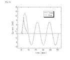
- FIG.5a is a graph illustrating a current flowing in the fault current limiter of FIG.4 according to an exemplary embodiment of the present disclosure
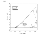
- FIG.5b is an enlarged view of a part in FIG.5a according to an exemplary embodiment of the present disclosure.
- the measurement unit (10) serves to continuously measure a current.
- the FFD (20) detects the fault current at a fast speed based thereon, transmits a turn-on signal to the SCR (80) to turn on the SCR (80).
- 'I' in FIG.5b defines a moment when a fault current is detected.
- 'J' in FIG.5b illustrates a moment when the SCR (80) is turned on.
- the meaning of the SCR (80) being turned on defines that a fault current flows to the current limiting circuit by a difference in impedances between the main circuit and the current limiting circuit.
- the FFD (20) transmits an open signal opening a contact point of the fast switch (40), whereby the contact point of the fast switch (40) is opened.
- an arc current flows across the contact point to increase the fault current toward the current limiting circuit in response to the arc impedance, whereby the fault current at the main circuit is slowed or weakened in its uptrend.
- the FFD (20) transmits a turn-off signal turning off the power semiconductor element (30) in the course of opening the fast switch (40), whereby the power semiconductor element (30) is turned off.
- FIG.5b illustrates a moment when the fast switch (40) is opened. At this time, the main circuit is cut off to quench a contact point arc current of the fast switch (40). 'L' illustrates that the fault current is completely diverted to the current limiting circuit.
- the fault current flows to the current limiting circuit, and after a predetermined period of time, the first power fuse (50) is melted, where 'M' defines the moment of the first power fuse (50) is melted or fused.
- the fault current flows to the current limiting resistance element (70), where 'O' illustrates a moment from which the current-limit is started by the current limiting resistance element (70). It can be noted that the fault current is limited in response to the impedance size of the current limiting resistance element (70).
- the fault current limiter is excellent in limiting effect of fault current and easy in control by adopting only the power semiconductor element (30) instead of superconductors.
Landscapes
- Engineering & Computer Science (AREA)
- Power Engineering (AREA)
- Emergency Protection Circuit Devices (AREA)
- Driving Mechanisms And Operating Circuits Of Arc-Extinguishing High-Tension Switches (AREA)
Abstract
Description
- The present disclosure relates to a fault current limiter, and more particularly to a fault current limiter used in electric power systems.
- A fault current limiter is a means of detecting a fault current generated by lightning, grounding and short-circuit and limiting the current to a normal level within several seconds, using a superconductor as a current limiting device which has substantially no resistance until certain up to a predetermined current value but rapidly represents a high resistance over a predetermined current value to limit the conducting current.
- The fault current limiter is concentrated with a huge amount of energy due to resistance generated by the superconductor, such that energy consumption of the superconductor increases as the voltage applied to the superconductor increases.
- That is, a superconductor exhibits zero resistance during its normal operation state in a system, however, when a fault current flows in the system, the superconductor is quenched to produce resistance which limits the fault current. At this time, the resistance may cause considerable energy to be applied to the current limiter. As a voltage applied to the system that runs the superconductor is high, the energy flowing in the superconductor correspondingly increases due to the impedance produced at the superconductor. Accordingly, lots of superconductors are needed to distribute the energy.
- Thus, to minimize the energy consumption of the superconductor, a large number of the superconductors is needed which leads to increasing the manufacturing cost, and a total volume increases in accordance with use of huge number of superconductors, thereby increasing the installation and cooling cost.
- That is, the superconductor is expensive in price and lots of superconductors mean large volume, which may increase the costs for installing and cooling the superconductor. To overcome the above problems, a hybrid-type superconducting fault current limiter (SFCL) including an existing circuit breaking means and a small number of superconductors has been disclosed. But the suggestion has failed to solve the price problem. As capacity of the resistive superconducting fault current limiter becomes large, size of the linear coils and number of windings have to be increased thereby to have a disadvantage in cost and operation.
-
FIG. 1 is a circuit diagram illustrating a structure of a hybrid-type superconducting fault current limiter according to prior art,FIG.2a is a current graph of the hybrid-type superconducting fault current limiter ofFIG. 1 ,FIG.2b is a graph illustrating an operation start time of the hybrid-type superconducting fault current limiter ofFIG. 1 ,FIG.2c is a graph illustrating an arc current in the hybrid-type superconducting fault current limiter ofFIG. 1 , andFIG.2d is a current graph of the hybrid-type superconducting fault current limiter where electric arc was not blocked by the main circuit of the fault current limiter. - Referring to
FIGS. 1 and2 , an electric current Itot passes through the closedcircuit breaker 210 and superconductor 100 (Imain) during a normal operation state without any fault, so that loss caused by occurrence of resistance is substantially '0'. However, in a case where a fault current(Ifuse) flows into the circuit, thesuperconductor 100 starts to be quenched (A) at a very high speed, and the fault current (Ifuse) bypasses to thedriving coil 220 due to impedance developed at thesuperconductor 100. - At this time, a magnetic field is generated by the current flowing into the
driving coil 220, and an eddy current having a diamagnetic component is induced at anelectromagnetic repeller 230 located over thedriving coil 220. - Accordingly, the
repeller 230 moves fast and opens acircuit breaker 210 mechanically linked with therepeller 230 thereby to cut off the inflow of the fault current into the superconductor 100 (B). - However, in the fault current limiter thus configured, the minute that the
circuit breaker 210 is open, an arc current occurs across thecircuit breaker 210, which causes the fault current to continue flowing into thesuperconductor 100. To eliminate the arc current, the fault current limiter is designed to close ashort contact 240 that is mechanically linked with the electromagnetic repeller 230 (C). - That is, the whole fault current is transferred through the
short contacts 240 to an auxiliary circuit, and therefore, the arc current across thecircuit breaker 210 is eliminated (D) and then the fault current is transferred to the auxiliary circuit and reduced by the current limiting unit 300 (E). - However, in the course of limiting the fault current thus explained, the electric arc occurring across the
circuit breaker 210 that is connected in series with thesuperconductor 100 may not be sufficiently removed before the current limitingunit 300 starts to operate due to difference in impedance between a main circuit formed with thesuperconductor 100 and the high-speed switch and the current limiting unit 300-formed auxiliary circuit that functions to limit the current (F). - Accordingly, an electric arc (arc current) is reproduced across the
circuit breaker 210 due to the difference in impedance between the main circuit and the auxiliary circuit (G), which can reduce the arc impedance, so that the fault current can go through thesuperconductor 100 that changes into a normal conductive state and thecircuit breaker 210 that becomes conductive due to the electric arc. At this time, most of voltage is applied to thesuperconductor 100 that is in a normal conductive state, so that the fault energy may flow into thesuperconductor 100, thereby damaging thesuperconductor 100. -
FIG.3 is a circuit diagram illustrating a hybrid-type superconducting fault current limiter according to prior art, proposed to solve the aforementioned problems, where apower semiconductor element 400 is added thereto. Thepower semiconductor element 400 is added to the main circuit to block an arc current generated after thesuperconductor 100 is quenched. - However, the fault current limiter according to
FIG.3 also fails to solve the problems, because superconductors are employed and the number of superconductors must be adjusted to adjust the operating current to thereby increase the costs for installing and cooling the superconductor and to reduce convenience in manipulation. - The present disclosure has been made to solve the foregoing problem(s) of the prior art, and therefore an object of certain embodiments of the present invention is to provide a fault current limiter configured to easily remove a fault current present therein.
- In one general aspect of the present disclosure, there is provided a fault current limiter, the current limiter comprising: a detector detecting an inflow of a fault current and transmitting a turn-on signal to a first switch and transmitting a turn-off signal to a power semiconductor element; the power semiconductor element changed to an OFF state by the turn-off signal; the first switch forming a current limiting circuit by being switched to an ON state by the turn-on signal; and a resistance element blocking the fault current, wherein the series connection between the resistance element and the first switch is connected in parallel to the power semiconductor element.
- Preferably, but not necessarily, the fault current limiter further comprises a second switch connected to the power semiconductor element in series to open a contact point therein, in a case the fault current is introduced, and to protect the power semiconductor element against the fault current.
- Preferably, but not necessarily, the serial connection between the second switch and the power semiconductor element is connected in parallel to the serial connection between the first switch and the resistance element.
- Preferably, but not necessarily, the detector transmits an open signal to the second switch, where the second switch is opened by the open signal.
- Preferably, but not necessarily, the fault current limiter further comprises a measurement unit measuring an inflow current, and the detector detects the inflow of fault current from a current measured by the measurement unit.
- Preferably, but not necessarily, the measurement unit includes a current transformer and a Rogowski coil.
- Preferably, but not necessarily, the fault current limiter further comprises a first power fuse connected to the resistance element in parallel to temporarily cut off the fault current introduced.
- Preferably, but not necessarily, the fault current limiter further comprises a second power fuse connected to the resistance element in series to cut off a fault current passing the resistance element.
- Preferably, but not necessarily, the detector transmits the turn-on signal prior to the open signal.
- Preferably, but not necessarily, the detector transmits the open signal prior to the turn-off signal.
- Preferably, but not necessarily, the power semiconductor element includes any one of an integrated gate communicated thyristor (IGBT), a gate turn-off thyristor (GTO), and an insulated gate bipolar transistor (IGCT).
- Preferably, but not necessarily, the first switch includes any one of an SCR (Silicon Controlled Rectifier) and a contact type contact point.
- The fault current limiter according to the present disclosure has an advantageous effect in that the fault current limiter is configured by removing superconductors and employing a power semiconductor element, whereby it is easy to control the fault current limiter and reliable fault current detection is enabled using a high speed fault detector.
- The fault current limiter according to the present disclosure has another advantageous effect in that a power fuse is used to initially limit a fault current, and the fault current is secondly limited using a resistor, whereby the fault current can be limited more perfectly, and an SCR is employed for the fault current limiter to prevent a current from being introduced into the fault current limiter in a case where a normal current flows.
- In order to explain the principle of the present disclosure, some accompanying drawings related to its preferred embodiments are below reported for the purpose of illustration, exemplification and description, although they are not intended to be exhaustive. The drawing figures depict one or more exemplary embodiments in accord with the present concepts, by way of example only, not by way of limitations. In the figures, like reference numerals refer to the same or similar elements.
- Thus, a wide variety of potential practical and useful embodiments will be more readily understood through the following detailed description of certain exemplary embodiments, with reference to the accompanying exemplary drawings in which:
-
FIG. 1 is a circuit diagram illustrating a structure of a hybrid-type superconducting fault current limiter according to prior art; -
FIG.2a is a current graph of the hybrid-type superconducting fault current limiter ofFIG. 1 ; -
FIG.2b is a graph illustrating an operation start time of the hybrid-type superconducting fault current limiter ofFIG.1; -
FIG.2c is a graph illustrating an arc current in the hybrid-type superconducting fault current limiter ofFIG.1; -
FIG.2d is a current graph of the hybrid-type superconducting fault current limiter where electric arc current is not blocked; -
FIG.3 is a circuit diagram illustrating a hybrid-type superconducting fault current limiter according to prior art; -
FIG.4 is a block diagram illustrating a fault current limiter according to the present disclosure; -
FIG.5a is a graph illustrating a current flowing in the fault current limiter ofFIG.4 according to an exemplary embodiment of the present disclosure; and -
FIG.5b is an enlarged view of a part inFIG.5a according to an exemplary embodiment of the present disclosure. - The disclosed embodiments and advantages thereof are best understood by referring to
FIGS. 1-5 of the drawings, like numerals being used for like and corresponding parts of the various drawings. Other features and advantages of the disclosed embodiments will be or will become apparent to one of ordinary skill in the art upon examination of the following figures and detailed description. It is intended that all such additional features and advantages be included within the scope of the disclosed embodiments, and protected by the accompanying drawings. Further, the illustrated figures are only exemplary and not intended to assert or imply any limitation with regard to the environment, architecture, or process in which different embodiments may be implemented. Accordingly, the described aspect is intended to embrace all such alterations, modifications, and variations that fall within the scope and novel idea of the present invention. - Meanwhile, the terminology used herein is for the purpose of describing particular implementations only and is not intended to be limiting of the present disclosure. The terms "first," "second," and the like, herein do not denote any order, quantity, or importance, but rather are used to distinguish one element from another. For example, a second constituent element may be denoted as a first constituent element without departing from the scope and spirit of the present disclosure, and similarly, a first constituent element may be denoted as a second constituent element.
- As used herein, the terms "a" and "an" herein do not denote a limitation of quantity, but rather denote the presence of at least one of the referenced item. That is, as used herein, the singular forms "a", "an" and "the" are intended to include the plural forms as well, unless the context clearly indicates otherwise.
- It will be understood that when an element is referred to as being "connected" or "coupled" to another element, it can be directly connected or coupled to the other element or intervening elements may be present. In contrast, when an element is referred to as being "directly connected" or "directly coupled" to another element, there are no intervening elements present.
- It will be further understood that the terms "comprises" and/or "comprising," or "includes" and/or "including" when used in this specification, specify the presence of stated features, regions, integers, steps, operations, elements, and/or components, but do not preclude the presence or addition of one or more other features, regions, integers, steps, operations, elements, components, and/or groups thereof.
- Also, "exemplary" is merely meant to mean an example, rather than the best. If is also to be appreciated that features, layers and/or elements depicted herein are illustrated with particular dimensions and/or orientations relative to one another for purposes of simplicity and ease of understanding, and that the actual dimensions and/or orientations may differ substantially from that illustrated.
- That is, in the drawings, the size and relative sizes of layers, regions and/or other elements may be exaggerated or reduced for clarity. Like numbers refer to like elements throughout and explanations that duplicate one another will be omitted. As may be used herein, the terms "substantially" and "approximately" provide an industry-accepted tolerance for its corresponding term and/or relativity between items.
- Hereinafter, a fault current limiter according to the present disclosure will be described in detail with reference to the accompanying drawings.
-
FIG.4 is a block diagram illustrating a fault current limiter according to the present disclosure. - Referring to
FIG.4 , a fault current limiter comprises a measurement unit (10), an FFD (Fast Failure Detector, 20), a power semiconductor element (30), a fast switch (40), first and second power fuses (50 and 60), a current limiting resistance element (70) and an SCR (Silicon Controlled Rectifier, 80). - The power semiconductor element (30) and the fast switch (40) are connected in series to form a main circuit.
- A serial connection between the SCR (80) and the first power fuse (50) is connected in parallel to a serial connection between the power semiconductor element (30) and the fast switch (40), and a serial connection between the current limiting resistance element (70) and the second power fuse (60) is connected in series to the first power fuse (50). These connections of the SCR (80), the first and second power fuses (50 and 60) and the current limiting resistance element (70) form the current limiting circuit.
- The measurement unit (10) measures a current and current accruement. The measurement unit (10) preferably includes a CT (Current Transformer) and a Rogowski coil. The CT and the Rogowski coil are well known in the art such that no more explanation thereto will be provided herein and omitted.
- In a case where the measurement unit (10) measures a current accruement to detect a failure, that is, in a case where a fault current is introduced, the FFD (20) transmits a turn-on signal turning on the SCR (80) to the SCR (80), transmits an open signal opening the fast switch (40) to the fast switch (40) and transmits a turn-off signal turning off the power semiconductor element (30) to the power semiconductor element (30), details of which will be described later.
- The power semiconductor element (30) maintains an ON state in normal times, but receives the turn-off signal from the FFD (20) and is switched to a OFF state, in a case where the fault current is introduced. The power semiconductor element (30) may be any one of an integrated gate communicated thyristor (IGBT), a gate turn-off thyristor (GTO), and an insulated gate bipolar transistor (IGCT), but it is not limited thereto.
- The fast switch (40) configured to maintain insulation at a fast speed serves to protect the power semiconductor element (30). The fast switch (40) receives an open signal from the FFD (20) to open a main circuit at a fast speed, in a case where the fault current is introduced.
- The SCR (80) configured to form the current limiting circuit is completed in turning-on prior to turn-off of the power semiconductor element (30). The SCR (80) is generally conductive at an instantaneous value of 50kA or more currents. The SCR (80) functions as a power switch. Although the present disclosure has illustrated the SCR (80) that functions as a power switch, the application of power switch is not limited to the SCR (80), and application of other elements capable of functioning as a power switch is not ruled out. For example, the power switch may be a contact type contact point. At this time, the meaning of the SCR (80) being turned on defines that a fault current flows in the current limiting circuit due to a difference in impedances between a main circuit and the current limiting circuit.
- The first power fuse (50) connected in parallel with the current limiting resistance element (70) is formed to initially cut off the fault current introduced into the current limiting circuit, and bypasses the fault current to the current limiting resistance element (70).
- The first power fuse (50) may be designed to cut off a large fault current. The first power fuse (50) initially cuts off the fault current introduced into the current limiting circuit, where the moment the first power fuse (50) is fused, the fault current is detoured to the current limiting resistance element (70).
- The second power fuse (60) connected to the current limiting resistance element (70) in series also cuts off the fault current introduced into the current limiting circuit and cuts off the fault current passing the current limiting resistance element (70). The second power fuse (60) may be designed to cut off a small fault current over the first power fuse (50). The fault current introduced into the second power fuse (60) is a residual current after the first power fuse (50) is fused and heated by the current limiting resistance element (70).
- Although the first and second power fuses (50, 60) are elements having the same function, the first power fuse (50) functions to bypass the fault current to the current limiting resistance element (70), while the second power fuse (60) functions to completely cut off the fault current. The physical structure of the power fuses is well known in the art, such that no further explanation will be given thereto.
- The current limiting resistance element (70) is a resistor limiting the introduced fault current to cut off the fault current in association with the second power fuse (60). Size of the impedance in the current limiting resistance element (70) is determined in consideration of cooperative operation with the second power fuse (60).
- Now, a detailed operation of the fault current limiter according to the present disclosure will be described with reference to the accompanying drawing.
FIG.5a is a graph illustrating a current flowing in the fault current limiter ofFIG.4 according to an exemplary embodiment of the present disclosure, andFIG.5b is an enlarged view of a part inFIG.5a according to an exemplary embodiment of the present disclosure. - First, all the currents pass the main circuit including the power semiconductor element (30) and the fast switch (40) in normal times, the current limiting circuit including the first and second power fuses (50 and 60) and the current limiting resistance element (70) is blocked of a current because the SCR (80) is turned off. The measurement unit (10) serves to continuously measure a current.
- In a case where the measurement unit (10) detects occurrence of a fault current, the FFD (20) detects the fault current at a fast speed based thereon, transmits a turn-on signal to the SCR (80) to turn on the SCR (80).
- 'I' in
FIG.5b defines a moment when a fault current is detected. 'J' inFIG.5b illustrates a moment when the SCR (80) is turned on. The meaning of the SCR (80) being turned on defines that a fault current flows to the current limiting circuit by a difference in impedances between the main circuit and the current limiting circuit. - Furthermore, the FFD (20) transmits an open signal opening a contact point of the fast switch (40), whereby the contact point of the fast switch (40) is opened. The moment the contact point of the fast switch (40) is opened, an arc current flows across the contact point to increase the fault current toward the current limiting circuit in response to the arc impedance, whereby the fault current at the main circuit is slowed or weakened in its uptrend.
- Still furthermore, the FFD (20) transmits a turn-off signal turning off the power semiconductor element (30) in the course of opening the fast switch (40), whereby the power semiconductor element (30) is turned off.
- 'K' in
FIG.5b illustrates a moment when the fast switch (40) is opened. At this time, the main circuit is cut off to quench a contact point arc current of the fast switch (40). 'L' illustrates that the fault current is completely diverted to the current limiting circuit. - Subsequently, the fault current flows to the current limiting circuit, and after a predetermined period of time, the first power fuse (50) is melted, where 'M' defines the moment of the first power fuse (50) is melted or fused.
- At the same time the first power fuse (50) is fused, the fault current flows to the current limiting resistance element (70), where 'O' illustrates a moment from which the current-limit is started by the current limiting resistance element (70). It can be noted that the fault current is limited in response to the impedance size of the current limiting resistance element (70).
- The fault current having passed the current limiting resistance element (70) flows in the second power fuse (60), where 'N' in
FIG.5b illustrates a moment the second power fuse (60) starts to melt. - As apparent from the foregoing, the fault current limiter is excellent in limiting effect of fault current and easy in control by adopting only the power semiconductor element (30) instead of superconductors.
- Although the present disclosure has been described with reference to a number of illustrative embodiments thereof, it should be understood that numerous other modifications and embodiments can be devised by those skilled in the art that will fall within the spirit and scope of the principles of this disclosure.
- More particularly, various variations and modifications are possible in the component parts and/or arrangements of subject combination arrangement within the scope of the disclosure, the drawings and the appended claims. In addition to variations and modifications in the component parts and/or arrangements, alternative uses will also be apparent to those skilled in the art.
Claims (12)
- A fault current limiter blocking a fault current, the fault current limiter characterized by: a detector (20) detecting an inflow of a fault current and transmitting a turn-on signal to a first switch (80) and transmitting a turn-off signal to a power semiconductor element (30); the power semiconductor element (30) changed to an OFF state by the turn-off signal; the first switch (80) forming a current limiting circuit by being switched to an ON state by the turn-on signal; and a resistance element (70) blocking the fault current, wherein the series connection between the resistance element (70) and the first switch (80) is connected in parallel to the power semiconductor element (30).
- The fault current limiter of claim 1, further characterized by a second switch (40) connected to the power semiconductor element (30) in series to open a contact point therein, in a case the fault current is introduced, and to protect the power semiconductor element (30) against the fault current.
- The fault current limiter of claim 2, characterized in that the serial connection between the second switch (40) and the power semiconductor element (30) is connected in parallel to the serial connection between the first switch (80) and the resistance element (70).
- The fault current limiter of claim 2 or 3, characterized in that the detector (20) transmits an open signal to the second switch (40), and the second switch (40) is opened by the open signal.
- The fault current limiter of any one claim from 1 to 4, further characterized by a measurement unit (10) measuring an inflow current, and the detector (20) detects the inflow of fault current from a current measured by the measurement unit (10).
- The fault current limiter of claim 5, characterized in that the measurement unit (10) includes a current transformer and a Rogowski coil.
- The fault current limiter of any one claim from 1 to 6, further characterized by a first power fuse (50) connected to the resistance element (70) in parallel to temporarily cut off the fault current introduced.
- The fault current limiter of any one claim from 1 to 7, further characterized by a second power fuse (60) connected to the resistance element (70) in series to cut off a fault current passing the resistance element (70).
- The fault current limiter of claim 4, characterized in that the detector (20) transmits the turn-on signal prior to the open signal.
- The fault current limiter of claim 4 or 9, characterized in that the detector (20) transmits the open signal prior to the turn-off signal.
- The fault current limiter of any one claim from 1 to 10, characterized in that the power semiconductor element (30) includes any one of an integrated gate communicated thyristor (IGBT), a gate turn-off thyristor (GTO), and an insulated gate bipolar transistor (IGCT).
- The fault current limiter of any one claim from 1 to 11, characterized in that the first switch (80) includes any one of an SCR (Silicon Controlled Rectifier) and a contact type contact point.
Applications Claiming Priority (1)
| Application Number | Priority Date | Filing Date | Title |
|---|---|---|---|
| KR1020110073239A KR101233003B1 (en) | 2011-07-22 | 2011-07-22 | Fault current limiter |
Publications (2)
| Publication Number | Publication Date |
|---|---|
| EP2549501A1 true EP2549501A1 (en) | 2013-01-23 |
| EP2549501B1 EP2549501B1 (en) | 2017-02-01 |
Family
ID=46785219
Family Applications (1)
| Application Number | Title | Priority Date | Filing Date |
|---|---|---|---|
| EP12174401.5A Not-in-force EP2549501B1 (en) | 2011-07-22 | 2012-06-29 | Fault current limiter |
Country Status (6)
| Country | Link |
|---|---|
| US (1) | US8749938B2 (en) |
| EP (1) | EP2549501B1 (en) |
| JP (1) | JP5612638B2 (en) |
| KR (1) | KR101233003B1 (en) |
| CN (1) | CN102891469B (en) |
| ES (1) | ES2623918T3 (en) |
Cited By (2)
| Publication number | Priority date | Publication date | Assignee | Title |
|---|---|---|---|---|
| EP2874257A1 (en) * | 2013-11-15 | 2015-05-20 | LSIS Co., Ltd. | Fault current limiter |
| EP3010030A1 (en) * | 2014-10-10 | 2016-04-20 | LSIS Co., Ltd. | Direct current circuit breaker and method using the same |
Families Citing this family (9)
| Publication number | Priority date | Publication date | Assignee | Title |
|---|---|---|---|---|
| FR2648473B1 (en) | 1989-06-19 | 1994-04-01 | Elf Aquitaine Ste Nale | SUB-BASED ADDITIVES FOR LUBRICATING OILS CONTAINING A MOLYBDENE COMPLEX, THEIR PREPARATION PROCESS AND COMPOSITIONS CONTAINING SAID ADDITIVES |
| KR101233048B1 (en) * | 2011-07-22 | 2013-02-13 | 엘에스산전 주식회사 | Fault current limiter |
| KR101233003B1 (en) * | 2011-07-22 | 2013-02-13 | 엘에스산전 주식회사 | Fault current limiter |
| CN105322582B (en) * | 2014-07-04 | 2018-04-13 | 上海宝信软件股份有限公司 | The Emergency power supply unit realized using controllable silicon technology |
| CN105703344A (en) * | 2016-03-17 | 2016-06-22 | 中国矿业大学 | Novel power cable short circuit current limiter |
| CN107887896A (en) * | 2017-12-20 | 2018-04-06 | 南京南瑞继保电气有限公司 | A kind of novel fault current limiter and control method |
| JP7200528B2 (en) * | 2017-12-20 | 2023-01-10 | 富士電機株式会社 | current breaker |
| KR102614414B1 (en) * | 2018-10-19 | 2023-12-14 | 한화오션 주식회사 | Short circuit current limit appparatus using igbt |
| KR102853787B1 (en) * | 2021-03-22 | 2025-09-03 | 엘에스일렉트릭(주) | Solid state circuit breaker(sscb) and control method thereof |
Citations (4)
| Publication number | Priority date | Publication date | Assignee | Title |
|---|---|---|---|---|
| US3723815A (en) * | 1970-12-28 | 1973-03-27 | Stanley Works | Electronic circuit protective device |
| US20110007432A1 (en) * | 2007-12-18 | 2011-01-13 | Spd Electrical Systems | Power Node Switching Center With Active Feedback Control Of Power Switches |
| WO2011057675A1 (en) * | 2009-11-16 | 2011-05-19 | Abb Technology Ag | Device and method to break the current of a power transmission or distribution line and current limiting arrangement |
| KR101044492B1 (en) * | 2010-04-23 | 2011-06-27 | 엘에스산전 주식회사 | Hybrid current limiter |
Family Cites Families (10)
| Publication number | Priority date | Publication date | Assignee | Title |
|---|---|---|---|---|
| JPH08315666A (en) * | 1995-05-12 | 1996-11-29 | Mitsubishi Electric Corp | Circuit breaker and circuit breaker |
| US6608470B1 (en) * | 1998-01-31 | 2003-08-19 | Motorola, Inc. | Overcharge protection device and methods for lithium based rechargeable batteries |
| JP2000133099A (en) | 1998-10-22 | 2000-05-12 | Toshiba Corp | Power circuit breaker |
| DE19927029A1 (en) * | 1999-06-04 | 2001-02-08 | Siemens Ag | Method for operating an electronic overcurrent release of a circuit breaker |
| JP3907998B2 (en) * | 2001-02-09 | 2007-04-18 | 株式会社東芝 | Substation protection control system |
| JP2004266978A (en) | 2003-03-04 | 2004-09-24 | Mitsubishi Electric Corp | Control circuit protection device |
| KR100888147B1 (en) | 2007-08-20 | 2009-03-13 | 한국전력공사 | Hybrid superconducting fault current limiter |
| US7738221B2 (en) * | 2007-12-07 | 2010-06-15 | Cooper Technologies Company | Transformer inrush current detector |
| KR101053665B1 (en) * | 2009-09-30 | 2011-08-03 | 한국전력공사 | Current-limiting device |
| KR101233003B1 (en) * | 2011-07-22 | 2013-02-13 | 엘에스산전 주식회사 | Fault current limiter |
-
2011
- 2011-07-22 KR KR1020110073239A patent/KR101233003B1/en active Active
-
2012
- 2012-06-29 ES ES12174401.5T patent/ES2623918T3/en active Active
- 2012-06-29 EP EP12174401.5A patent/EP2549501B1/en not_active Not-in-force
- 2012-07-06 US US13/543,741 patent/US8749938B2/en active Active
- 2012-07-20 JP JP2012161705A patent/JP5612638B2/en not_active Expired - Fee Related
- 2012-07-23 CN CN201210256809.1A patent/CN102891469B/en active Active
Patent Citations (4)
| Publication number | Priority date | Publication date | Assignee | Title |
|---|---|---|---|---|
| US3723815A (en) * | 1970-12-28 | 1973-03-27 | Stanley Works | Electronic circuit protective device |
| US20110007432A1 (en) * | 2007-12-18 | 2011-01-13 | Spd Electrical Systems | Power Node Switching Center With Active Feedback Control Of Power Switches |
| WO2011057675A1 (en) * | 2009-11-16 | 2011-05-19 | Abb Technology Ag | Device and method to break the current of a power transmission or distribution line and current limiting arrangement |
| KR101044492B1 (en) * | 2010-04-23 | 2011-06-27 | 엘에스산전 주식회사 | Hybrid current limiter |
Cited By (4)
| Publication number | Priority date | Publication date | Assignee | Title |
|---|---|---|---|---|
| EP2874257A1 (en) * | 2013-11-15 | 2015-05-20 | LSIS Co., Ltd. | Fault current limiter |
| US9490628B2 (en) | 2013-11-15 | 2016-11-08 | Lsis Co., Ltd. | Fault current limiter |
| EP3010030A1 (en) * | 2014-10-10 | 2016-04-20 | LSIS Co., Ltd. | Direct current circuit breaker and method using the same |
| US10116132B2 (en) | 2014-10-10 | 2018-10-30 | Lsis Co., Ltd. | Device for efficient direct current interruption |
Also Published As
| Publication number | Publication date |
|---|---|
| ES2623918T3 (en) | 2017-07-12 |
| CN102891469A (en) | 2013-01-23 |
| EP2549501B1 (en) | 2017-02-01 |
| US8749938B2 (en) | 2014-06-10 |
| US20130021706A1 (en) | 2013-01-24 |
| KR20130011818A (en) | 2013-01-30 |
| KR101233003B1 (en) | 2013-02-13 |
| JP5612638B2 (en) | 2014-10-22 |
| CN102891469B (en) | 2016-04-13 |
| JP2013027309A (en) | 2013-02-04 |
Similar Documents
| Publication | Publication Date | Title |
|---|---|---|
| US8749938B2 (en) | Fault current limiter | |
| US8760834B2 (en) | Fault current limiter | |
| KR100888147B1 (en) | Hybrid superconducting fault current limiter | |
| CN102656656B (en) | An HVDC breaker and control apparatus for controlling an HVDC breaker | |
| KR101044492B1 (en) | Hybrid current limiter | |
| KR20160081716A (en) | Dc circuit breaker and method for breaking of dc circuit breaker | |
| KR20020052171A (en) | Arc-fault detecting circuit breaker system | |
| KR101821439B1 (en) | Fault current limiter | |
| EP3363086B1 (en) | Semiconductor circuit interruption devices using current filtering to improve device coordination | |
| CN101728812A (en) | Line commutation type fault current limiter | |
| JP6727470B1 (en) | Superconducting coil protector | |
| CN122001350A (en) | Switching system and electrical device |
Legal Events
| Date | Code | Title | Description |
|---|---|---|---|
| PUAI | Public reference made under article 153(3) epc to a published international application that has entered the european phase |
Free format text: ORIGINAL CODE: 0009012 |
|
| AK | Designated contracting states |
Kind code of ref document: A1 Designated state(s): AL AT BE BG CH CY CZ DE DK EE ES FI FR GB GR HR HU IE IS IT LI LT LU LV MC MK MT NL NO PL PT RO RS SE SI SK SM TR |
|
| AX | Request for extension of the european patent |
Extension state: BA ME |
|
| 17P | Request for examination filed |
Effective date: 20130723 |
|
| RBV | Designated contracting states (corrected) |
Designated state(s): AL AT BE BG CH CY CZ DE DK EE ES FI FR GB GR HR HU IE IS IT LI LT LU LV MC MK MT NL NO PL PT RO RS SE SI SK SM TR |
|
| GRAP | Despatch of communication of intention to grant a patent |
Free format text: ORIGINAL CODE: EPIDOSNIGR1 |
|
| RIC1 | Information provided on ipc code assigned before grant |
Ipc: H02H 9/02 20060101ALI20160825BHEP Ipc: H01H 9/54 20060101AFI20160825BHEP |
|
| INTG | Intention to grant announced |
Effective date: 20160922 |
|
| GRAS | Grant fee paid |
Free format text: ORIGINAL CODE: EPIDOSNIGR3 |
|
| GRAA | (expected) grant |
Free format text: ORIGINAL CODE: 0009210 |
|
| AK | Designated contracting states |
Kind code of ref document: B1 Designated state(s): AL AT BE BG CH CY CZ DE DK EE ES FI FR GB GR HR HU IE IS IT LI LT LU LV MC MK MT NL NO PL PT RO RS SE SI SK SM TR |
|
| REG | Reference to a national code |
Ref country code: GB Ref legal event code: FG4D |
|
| REG | Reference to a national code |
Ref country code: CH Ref legal event code: EP Ref country code: AT Ref legal event code: REF Ref document number: 866166 Country of ref document: AT Kind code of ref document: T Effective date: 20170215 |
|
| REG | Reference to a national code |
Ref country code: IE Ref legal event code: FG4D |
|
| REG | Reference to a national code |
Ref country code: DE Ref legal event code: R096 Ref document number: 602012028175 Country of ref document: DE |
|
| REG | Reference to a national code |
Ref country code: NL Ref legal event code: MP Effective date: 20170201 |
|
| REG | Reference to a national code |
Ref country code: LT Ref legal event code: MG4D |
|
| REG | Reference to a national code |
Ref country code: AT Ref legal event code: MK05 Ref document number: 866166 Country of ref document: AT Kind code of ref document: T Effective date: 20170201 |
|
| REG | Reference to a national code |
Ref country code: FR Ref legal event code: PLFP Year of fee payment: 6 |
|
| REG | Reference to a national code |
Ref country code: ES Ref legal event code: FG2A Ref document number: 2623918 Country of ref document: ES Kind code of ref document: T3 Effective date: 20170712 |
|
| PG25 | Lapsed in a contracting state [announced via postgrant information from national office to epo] |
Ref country code: HR Free format text: LAPSE BECAUSE OF FAILURE TO SUBMIT A TRANSLATION OF THE DESCRIPTION OR TO PAY THE FEE WITHIN THE PRESCRIBED TIME-LIMIT Effective date: 20170201 Ref country code: NO Free format text: LAPSE BECAUSE OF FAILURE TO SUBMIT A TRANSLATION OF THE DESCRIPTION OR TO PAY THE FEE WITHIN THE PRESCRIBED TIME-LIMIT Effective date: 20170501 Ref country code: FI Free format text: LAPSE BECAUSE OF FAILURE TO SUBMIT A TRANSLATION OF THE DESCRIPTION OR TO PAY THE FEE WITHIN THE PRESCRIBED TIME-LIMIT Effective date: 20170201 Ref country code: LT Free format text: LAPSE BECAUSE OF FAILURE TO SUBMIT A TRANSLATION OF THE DESCRIPTION OR TO PAY THE FEE WITHIN THE PRESCRIBED TIME-LIMIT Effective date: 20170201 Ref country code: GR Free format text: LAPSE BECAUSE OF FAILURE TO SUBMIT A TRANSLATION OF THE DESCRIPTION OR TO PAY THE FEE WITHIN THE PRESCRIBED TIME-LIMIT Effective date: 20170502 Ref country code: IS Free format text: LAPSE BECAUSE OF FAILURE TO SUBMIT A TRANSLATION OF THE DESCRIPTION OR TO PAY THE FEE WITHIN THE PRESCRIBED TIME-LIMIT Effective date: 20170601 |
|
| PG25 | Lapsed in a contracting state [announced via postgrant information from national office to epo] |
Ref country code: NL Free format text: LAPSE BECAUSE OF FAILURE TO SUBMIT A TRANSLATION OF THE DESCRIPTION OR TO PAY THE FEE WITHIN THE PRESCRIBED TIME-LIMIT Effective date: 20170201 Ref country code: PT Free format text: LAPSE BECAUSE OF FAILURE TO SUBMIT A TRANSLATION OF THE DESCRIPTION OR TO PAY THE FEE WITHIN THE PRESCRIBED TIME-LIMIT Effective date: 20170601 Ref country code: AT Free format text: LAPSE BECAUSE OF FAILURE TO SUBMIT A TRANSLATION OF THE DESCRIPTION OR TO PAY THE FEE WITHIN THE PRESCRIBED TIME-LIMIT Effective date: 20170201 Ref country code: PL Free format text: LAPSE BECAUSE OF FAILURE TO SUBMIT A TRANSLATION OF THE DESCRIPTION OR TO PAY THE FEE WITHIN THE PRESCRIBED TIME-LIMIT Effective date: 20170201 Ref country code: SE Free format text: LAPSE BECAUSE OF FAILURE TO SUBMIT A TRANSLATION OF THE DESCRIPTION OR TO PAY THE FEE WITHIN THE PRESCRIBED TIME-LIMIT Effective date: 20170201 Ref country code: RS Free format text: LAPSE BECAUSE OF FAILURE TO SUBMIT A TRANSLATION OF THE DESCRIPTION OR TO PAY THE FEE WITHIN THE PRESCRIBED TIME-LIMIT Effective date: 20170201 Ref country code: BG Free format text: LAPSE BECAUSE OF FAILURE TO SUBMIT A TRANSLATION OF THE DESCRIPTION OR TO PAY THE FEE WITHIN THE PRESCRIBED TIME-LIMIT Effective date: 20170501 Ref country code: LV Free format text: LAPSE BECAUSE OF FAILURE TO SUBMIT A TRANSLATION OF THE DESCRIPTION OR TO PAY THE FEE WITHIN THE PRESCRIBED TIME-LIMIT Effective date: 20170201 |
|
| PG25 | Lapsed in a contracting state [announced via postgrant information from national office to epo] |
Ref country code: EE Free format text: LAPSE BECAUSE OF FAILURE TO SUBMIT A TRANSLATION OF THE DESCRIPTION OR TO PAY THE FEE WITHIN THE PRESCRIBED TIME-LIMIT Effective date: 20170201 Ref country code: SK Free format text: LAPSE BECAUSE OF FAILURE TO SUBMIT A TRANSLATION OF THE DESCRIPTION OR TO PAY THE FEE WITHIN THE PRESCRIBED TIME-LIMIT Effective date: 20170201 Ref country code: CZ Free format text: LAPSE BECAUSE OF FAILURE TO SUBMIT A TRANSLATION OF THE DESCRIPTION OR TO PAY THE FEE WITHIN THE PRESCRIBED TIME-LIMIT Effective date: 20170201 Ref country code: RO Free format text: LAPSE BECAUSE OF FAILURE TO SUBMIT A TRANSLATION OF THE DESCRIPTION OR TO PAY THE FEE WITHIN THE PRESCRIBED TIME-LIMIT Effective date: 20170201 |
|
| REG | Reference to a national code |
Ref country code: DE Ref legal event code: R097 Ref document number: 602012028175 Country of ref document: DE |
|
| PG25 | Lapsed in a contracting state [announced via postgrant information from national office to epo] |
Ref country code: SM Free format text: LAPSE BECAUSE OF FAILURE TO SUBMIT A TRANSLATION OF THE DESCRIPTION OR TO PAY THE FEE WITHIN THE PRESCRIBED TIME-LIMIT Effective date: 20170201 Ref country code: DK Free format text: LAPSE BECAUSE OF FAILURE TO SUBMIT A TRANSLATION OF THE DESCRIPTION OR TO PAY THE FEE WITHIN THE PRESCRIBED TIME-LIMIT Effective date: 20170201 |
|
| PLBE | No opposition filed within time limit |
Free format text: ORIGINAL CODE: 0009261 |
|
| STAA | Information on the status of an ep patent application or granted ep patent |
Free format text: STATUS: NO OPPOSITION FILED WITHIN TIME LIMIT |
|
| 26N | No opposition filed |
Effective date: 20171103 |
|
| PG25 | Lapsed in a contracting state [announced via postgrant information from national office to epo] |
Ref country code: MC Free format text: LAPSE BECAUSE OF FAILURE TO SUBMIT A TRANSLATION OF THE DESCRIPTION OR TO PAY THE FEE WITHIN THE PRESCRIBED TIME-LIMIT Effective date: 20170201 |
|
| REG | Reference to a national code |
Ref country code: CH Ref legal event code: PL |
|
| PG25 | Lapsed in a contracting state [announced via postgrant information from national office to epo] |
Ref country code: SI Free format text: LAPSE BECAUSE OF FAILURE TO SUBMIT A TRANSLATION OF THE DESCRIPTION OR TO PAY THE FEE WITHIN THE PRESCRIBED TIME-LIMIT Effective date: 20170201 |
|
| REG | Reference to a national code |
Ref country code: IE Ref legal event code: MM4A |
|
| REG | Reference to a national code |
Ref country code: FR Ref legal event code: PLFP Year of fee payment: 7 |
|
| PG25 | Lapsed in a contracting state [announced via postgrant information from national office to epo] |
Ref country code: LI Free format text: LAPSE BECAUSE OF NON-PAYMENT OF DUE FEES Effective date: 20170630 Ref country code: IE Free format text: LAPSE BECAUSE OF NON-PAYMENT OF DUE FEES Effective date: 20170629 Ref country code: LU Free format text: LAPSE BECAUSE OF NON-PAYMENT OF DUE FEES Effective date: 20170629 Ref country code: CH Free format text: LAPSE BECAUSE OF NON-PAYMENT OF DUE FEES Effective date: 20170630 |
|
| REG | Reference to a national code |
Ref country code: BE Ref legal event code: MM Effective date: 20170630 |
|
| PG25 | Lapsed in a contracting state [announced via postgrant information from national office to epo] |
Ref country code: BE Free format text: LAPSE BECAUSE OF NON-PAYMENT OF DUE FEES Effective date: 20170630 |
|
| PG25 | Lapsed in a contracting state [announced via postgrant information from national office to epo] |
Ref country code: MT Free format text: LAPSE BECAUSE OF NON-PAYMENT OF DUE FEES Effective date: 20170629 |
|
| PG25 | Lapsed in a contracting state [announced via postgrant information from national office to epo] |
Ref country code: HU Free format text: LAPSE BECAUSE OF FAILURE TO SUBMIT A TRANSLATION OF THE DESCRIPTION OR TO PAY THE FEE WITHIN THE PRESCRIBED TIME-LIMIT; INVALID AB INITIO Effective date: 20120629 |
|
| PG25 | Lapsed in a contracting state [announced via postgrant information from national office to epo] |
Ref country code: CY Free format text: LAPSE BECAUSE OF NON-PAYMENT OF DUE FEES Effective date: 20170201 |
|
| PG25 | Lapsed in a contracting state [announced via postgrant information from national office to epo] |
Ref country code: MK Free format text: LAPSE BECAUSE OF FAILURE TO SUBMIT A TRANSLATION OF THE DESCRIPTION OR TO PAY THE FEE WITHIN THE PRESCRIBED TIME-LIMIT Effective date: 20170201 |
|
| PG25 | Lapsed in a contracting state [announced via postgrant information from national office to epo] |
Ref country code: TR Free format text: LAPSE BECAUSE OF FAILURE TO SUBMIT A TRANSLATION OF THE DESCRIPTION OR TO PAY THE FEE WITHIN THE PRESCRIBED TIME-LIMIT Effective date: 20170201 |
|
| PGFP | Annual fee paid to national office [announced via postgrant information from national office to epo] |
Ref country code: FR Payment date: 20200306 Year of fee payment: 9 |
|
| PG25 | Lapsed in a contracting state [announced via postgrant information from national office to epo] |
Ref country code: AL Free format text: LAPSE BECAUSE OF FAILURE TO SUBMIT A TRANSLATION OF THE DESCRIPTION OR TO PAY THE FEE WITHIN THE PRESCRIBED TIME-LIMIT Effective date: 20170201 |
|
| PGFP | Annual fee paid to national office [announced via postgrant information from national office to epo] |
Ref country code: DE Payment date: 20200305 Year of fee payment: 9 |
|
| PGFP | Annual fee paid to national office [announced via postgrant information from national office to epo] |
Ref country code: GB Payment date: 20200408 Year of fee payment: 9 Ref country code: IT Payment date: 20200622 Year of fee payment: 9 |
|
| PGFP | Annual fee paid to national office [announced via postgrant information from national office to epo] |
Ref country code: ES Payment date: 20200709 Year of fee payment: 9 |
|
| REG | Reference to a national code |
Ref country code: DE Ref legal event code: R119 Ref document number: 602012028175 Country of ref document: DE |
|
| GBPC | Gb: european patent ceased through non-payment of renewal fee |
Effective date: 20210629 |
|
| PG25 | Lapsed in a contracting state [announced via postgrant information from national office to epo] |
Ref country code: GB Free format text: LAPSE BECAUSE OF NON-PAYMENT OF DUE FEES Effective date: 20210629 Ref country code: DE Free format text: LAPSE BECAUSE OF NON-PAYMENT OF DUE FEES Effective date: 20220101 |
|
| PG25 | Lapsed in a contracting state [announced via postgrant information from national office to epo] |
Ref country code: FR Free format text: LAPSE BECAUSE OF NON-PAYMENT OF DUE FEES Effective date: 20210630 |
|
| PG25 | Lapsed in a contracting state [announced via postgrant information from national office to epo] |
Ref country code: IT Free format text: LAPSE BECAUSE OF NON-PAYMENT OF DUE FEES Effective date: 20210629 |
|
| REG | Reference to a national code |
Ref country code: ES Ref legal event code: FD2A Effective date: 20220902 |
|
| PG25 | Lapsed in a contracting state [announced via postgrant information from national office to epo] |
Ref country code: ES Free format text: LAPSE BECAUSE OF NON-PAYMENT OF DUE FEES Effective date: 20210630 |