EP2549333B1 - Printing apparatus, control method for the printing apparatus and program - Google Patents
Printing apparatus, control method for the printing apparatus and program Download PDFInfo
- Publication number
- EP2549333B1 EP2549333B1 EP12176725.5A EP12176725A EP2549333B1 EP 2549333 B1 EP2549333 B1 EP 2549333B1 EP 12176725 A EP12176725 A EP 12176725A EP 2549333 B1 EP2549333 B1 EP 2549333B1
- Authority
- EP
- European Patent Office
- Prior art keywords
- recording material
- storing means
- printing apparatus
- run
- determined
- Prior art date
- Legal status (The legal status is an assumption and is not a legal conclusion. Google has not performed a legal analysis and makes no representation as to the accuracy of the status listed.)
- Active
Links
- 238000000034 method Methods 0.000 title claims description 23
- 239000000463 material Substances 0.000 claims description 58
- 238000004891 communication Methods 0.000 claims description 11
- 238000012545 processing Methods 0.000 description 18
- 238000010586 diagram Methods 0.000 description 10
- 238000012546 transfer Methods 0.000 description 9
- 238000011161 development Methods 0.000 description 7
- 230000002457 bidirectional effect Effects 0.000 description 4
- 230000006870 function Effects 0.000 description 2
- 230000003287 optical effect Effects 0.000 description 2
- 230000004044 response Effects 0.000 description 2
- 241000238876 Acari Species 0.000 description 1
- 239000003086 colorant Substances 0.000 description 1
- 238000001514 detection method Methods 0.000 description 1
- 238000003384 imaging method Methods 0.000 description 1
- 239000000203 mixture Substances 0.000 description 1
- 230000003068 static effect Effects 0.000 description 1
Images


Classifications
-
- G—PHYSICS
- G03—PHOTOGRAPHY; CINEMATOGRAPHY; ANALOGOUS TECHNIQUES USING WAVES OTHER THAN OPTICAL WAVES; ELECTROGRAPHY; HOLOGRAPHY
- G03G—ELECTROGRAPHY; ELECTROPHOTOGRAPHY; MAGNETOGRAPHY
- G03G21/00—Arrangements not provided for by groups G03G13/00 - G03G19/00, e.g. cleaning, elimination of residual charge
-
- G—PHYSICS
- G03—PHOTOGRAPHY; CINEMATOGRAPHY; ANALOGOUS TECHNIQUES USING WAVES OTHER THAN OPTICAL WAVES; ELECTROGRAPHY; HOLOGRAPHY
- G03G—ELECTROGRAPHY; ELECTROPHOTOGRAPHY; MAGNETOGRAPHY
- G03G15/00—Apparatus for electrographic processes using a charge pattern
- G03G15/01—Apparatus for electrographic processes using a charge pattern for producing multicoloured copies
- G03G15/0142—Structure of complete machines
- G03G15/0147—Structure of complete machines using a single reusable electrographic recording member
- G03G15/0152—Structure of complete machines using a single reusable electrographic recording member onto which the monocolour toner images are superposed before common transfer from the recording member
- G03G15/0173—Structure of complete machines using a single reusable electrographic recording member onto which the monocolour toner images are superposed before common transfer from the recording member plural rotations of recording member to produce multicoloured copy, e.g. rotating set of developing units
-
- G—PHYSICS
- G03—PHOTOGRAPHY; CINEMATOGRAPHY; ANALOGOUS TECHNIQUES USING WAVES OTHER THAN OPTICAL WAVES; ELECTROGRAPHY; HOLOGRAPHY
- G03G—ELECTROGRAPHY; ELECTROPHOTOGRAPHY; MAGNETOGRAPHY
- G03G15/00—Apparatus for electrographic processes using a charge pattern
-
- G—PHYSICS
- G03—PHOTOGRAPHY; CINEMATOGRAPHY; ANALOGOUS TECHNIQUES USING WAVES OTHER THAN OPTICAL WAVES; ELECTROGRAPHY; HOLOGRAPHY
- G03G—ELECTROGRAPHY; ELECTROPHOTOGRAPHY; MAGNETOGRAPHY
- G03G15/00—Apparatus for electrographic processes using a charge pattern
- G03G15/06—Apparatus for electrographic processes using a charge pattern for developing
- G03G15/08—Apparatus for electrographic processes using a charge pattern for developing using a solid developer, e.g. powder developer
- G03G15/0822—Arrangements for preparing, mixing, supplying or dispensing developer
- G03G15/0865—Arrangements for supplying new developer
-
- G—PHYSICS
- G03—PHOTOGRAPHY; CINEMATOGRAPHY; ANALOGOUS TECHNIQUES USING WAVES OTHER THAN OPTICAL WAVES; ELECTROGRAPHY; HOLOGRAPHY
- G03G—ELECTROGRAPHY; ELECTROPHOTOGRAPHY; MAGNETOGRAPHY
- G03G15/00—Apparatus for electrographic processes using a charge pattern
- G03G15/55—Self-diagnostics; Malfunction or lifetime display
- G03G15/553—Monitoring or warning means for exhaustion or lifetime end of consumables, e.g. indication of insufficient copy sheet quantity for a job
- G03G15/556—Monitoring or warning means for exhaustion or lifetime end of consumables, e.g. indication of insufficient copy sheet quantity for a job for toner consumption, e.g. pixel counting, toner coverage detection or toner density measurement
-
- G—PHYSICS
- G03—PHOTOGRAPHY; CINEMATOGRAPHY; ANALOGOUS TECHNIQUES USING WAVES OTHER THAN OPTICAL WAVES; ELECTROGRAPHY; HOLOGRAPHY
- G03G—ELECTROGRAPHY; ELECTROPHOTOGRAPHY; MAGNETOGRAPHY
- G03G21/00—Arrangements not provided for by groups G03G13/00 - G03G19/00, e.g. cleaning, elimination of residual charge
- G03G21/16—Mechanical means for facilitating the maintenance of the apparatus, e.g. modular arrangements
- G03G21/1604—Arrangement or disposition of the entire apparatus
- G03G21/1623—Means to access the interior of the apparatus
- G03G21/1633—Means to access the interior of the apparatus using doors or covers
-
- G—PHYSICS
- G03—PHOTOGRAPHY; CINEMATOGRAPHY; ANALOGOUS TECHNIQUES USING WAVES OTHER THAN OPTICAL WAVES; ELECTROGRAPHY; HOLOGRAPHY
- G03G—ELECTROGRAPHY; ELECTROPHOTOGRAPHY; MAGNETOGRAPHY
- G03G2215/00—Apparatus for electrophotographic processes
- G03G2215/01—Apparatus for electrophotographic processes for producing multicoloured copies
- G03G2215/0103—Plural electrographic recording members
- G03G2215/0109—Single transfer point used by plural recording members
- G03G2215/0116—Rotating set of recording members
Definitions
- the present invention relates to a printing apparatus including a storing unit for storing a recording material, and configured to perform printing by using the recording material.
- the printing apparatus needs to detect a toner-out cartridge.
- an optical sensor is used to detect remaining amount of toner in a toner cartridge, and when a cartridge that has run out of toner is detected, the cartridge is moved to its replacement position. Thus, the user can replace the toner cartridge smoothly.
- JP 2005-250196 describes printing in a specific color in a large quantity and bringing the specific-color printable condition in a short period of time, in an image forming apparatus in which a printing operation can be performed using toner in a cartridge positioned in the developing position by selectively bringing a plurality of cartridges having toner of the specific color into the developing position.
- a printing operation can be performed using toner in a cartridge positioned in the developing position by selectively bringing a plurality of cartridges having toner of the specific color into the developing position.
- determination is made whether the development cartridges attached to a development unit can be used or not. Among the cartridges that can be used, only a selected one is subjected to a printing preparing operation.
- JP 2007-155762 describes an image forming apparatus provided with a control means for moving the toner cartridge of the specific color to the replacing position of the toner cartridge by a moving body when a toner residual amount detection means detects that the toner cartridge of the specific color has no toner substantially.
- a printing apparatus as specified in claim 1.
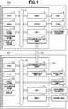
- Fig. 1 is a block diagram illustrating a printing system according to an exemplary embodiment of the present in invention.
- a computer 100 communicates with a printing apparatus 101 through a bidirectional interface 24.
- the bidirectional interface 24 may be a wired interface, such as LAN or USB, or a wireless LAN.
- the computer 100 includes a central processing unit (CPU) 1, a random access memory (RAM) 2, a read only memory (ROM) 3, a system bus 4, a keyboard controller 5, a cathode ray tube (CRT) controller 6, a memory controller 7, a communication unit 8, a keyboard 9, a CRT display 10, and an external memory 11.
- CPU central processing unit
- RAM random access memory
- ROM read only memory
- system bus 4 system bus 4
- keyboard controller 5 a cathode ray tube (CRT) controller 6
- CTR cathode ray tube
- memory controller 7 a communication unit 8
- a keyboard 9, a CRT display 10 and an external memory 11.
- the CPU 1 performs various kinds of data processing based on programs stored in a program ROM.
- the CPU 1 processes documents including graphics, images, characters, tables (such as spreadsheets) or mixtures of them.
- the CPU 1 collectively controls devices connected to the system bus 4.
- the CPU 1 develops outline fonts in a RAM for display information, set on the RAM 2, and realizes WYSIWYG (What You See Is What You Get).
- the CPU 1 also opens various kinds of windows and executes various kinds of data processing on commands issued by the mouse cursor on the CRT display unit 10.
- the RAM 2 serves as a main memory or a work memory of the CPU 1.
- the ROM 3 includes a font ROM, a program ROM, and a data ROM.
- the font ROM stores font data used in document processing.
- the program ROM stores not only a control program for controlling the computer 100 but also stores programs such as a printer selector and a network printer driver.
- the data ROM stores various kinds of data used in document processing.
- the keyboard controller 5 controls key-in operations from the keyboard 9 and a pointing device (not illustrated).
- the CRT controller 6 controls display on the CRT display unit 10.
- the memory controller 7 controls access to the external memory 11.
- the external memory 11 is a memory device to store a boot program, application programs, font data, user files, and edition files.
- the external memory 11 may be a hard disk, a flash EEPROM memory or a USB memory.
- the communication unit 8 controls communication with the printing apparatus 101 through the bidirectional interface 24.
- the printing apparatus 101 includes a printer controller 102, the operation unit 14, the printing unit 17, the external memory 21, and the hard disk 23.
- the printer controller 102 includes a CPU 12, a ROM 13, a system bus 15, a printing unit interface 16, a communication unit 18, a RAM 19, a memory controller 20, and a disk controller 22.
- the CPU 12 executes a control program stored in the program ROM and a control program stored in the external memory 21 to perform data processing.
- the CPU 12 based on the control program, collectively controls various devices connected to the system bus 15. For example, the CPU 12 generates image data, and transmits an image signal based on the image data to the printing unit 17 through the printing device 16.
- the CPU 12 transmits a control signal to the printing unit 17 through the printing unit interface 16. In addition, the CPU 12 transmits information about the printing apparatus 101 to the computer 100 through the communication unit 18.
- the ROM 13 includes the font ROM, the program ROM, and the data ROM.
- the font ROM stores font data used to generate image data.
- the program ROM stores a control program which is executed by the CPU12.
- the data ROM stores various kinds of data to be used in data processing, for example.
- the operation unit 14 is an operation panel including switches and LED displays to display the key input and information.
- the operation unit 14 may be formed by a touch panel.
- the printing unit interface 16 controls communication with the printing unit 17.
- the communication unit 18 controls communication with the computer 100 performed through the bidirectional interface 24.
- the RAM 19 serves as the main memory and the work memory of the CPU 12.
- the memory capacity of the RAM 19 can be expanded by adding an optional RAM to an expansion port (not illustrated) .
- the RAM 19 can also serve as an image data memory area to store rasterized image data or an environment data memory area to store environment data or a nonvolatile RAM (NVRAM) to store various kinds of parameters.
- NVRAM nonvolatile RAM
- the memory controller 20 controls access to the external memory 21.
- the external memory 21 such as an IC card or a USB memory, can store font data, an emulation program, and form data.
- the disk controller 22 controls access to the hard disk 23.
- the hard disk 23 stores print data and a control program, for example.
- Fig. 2 is a sectional view of the printing apparatus 101.
- Fig. 2 illustrates an internal structure of a color laser printer of a rotary development system.
- toner is used as a recording material for printing.
- a scanner 711 includes a laser output unit (not illustrated) configured to convert an image signal from the printer controller 102 into a light signal (laser light), an octahedral polygon mirror 712, a motor (not illustrated) to rotate the polygon mirror 712, and an f/ ⁇ lens (imaging lens) 713.
- a laser output unit (not illustrated) configured to convert an image signal from the printer controller 102 into a light signal (laser light), an octahedral polygon mirror 712, a motor (not illustrated) to rotate the polygon mirror 712, and an f/ ⁇ lens (imaging lens) 713.
- the laser beam emitted from the laser output unit is reflected from a side face of the polygon mirror 712, passes through the f/ ⁇ lens 713 and the reflection mirror 714, and thus scans the surface of photosensitive drum 715 linearly (raster scan).
- the photosensitive drum 715 rotates in the arrow direction as illustrated in Fig. 2 .
- an electrostatic latent image corresponding to an image represented by an image signal is formed on the surface of the photosensitive drum 715.
- a primary charging unit 717 Around the photosensitive drum 715, there are arranged a primary charging unit 717, a whole surface exposure lamp 718, a cleaner unit 723 to collect the toner not transferred to a paper (residual toner), and a pre-exposure charger 724.
- a developing unit 726 is a unit to develop the electrostatic latent image formed on the surface of the photosensitive drum 715.
- the developing unit 726 includes the following units.
- the toner cartridges 730C, 730M, 730Y, and 730BK each hold toner as developer.
- a toner remaining amount sensor (not illustrated) is used to measure remaining toner amount of each toner cartridge.
- Development sleeves 731C, 731M, 731Y, and 731BK are respectively brought into contact with the photosensitive drum 715 to develop the latent images into visible images by the developer.
- Screws 732 convey the developers from the toner cartridges 730C, 730M, 730Y, and 730BK respectively to the development sleeves 731C, 731M, 731Y, and 731BK.
- developers for cyan, magenta, yellow, and black are used to form toner images on the photosensitive drum 715.
- the toner cartridges, the development sleeves, and the screws are disposed around the central axis P.
- the symbols attached to the components Y, M, C and BK represent different colors. More specifically, C is cyan, M is magenta, Y is yellow, and BK is black.
- a cover 701 can be opened or closed. The user can open the cover 701 and replace the toner cartridges.
- the toner cartridge directly below the cover 701 can be dismounted.
- the position directly below the cover 701 is referred to as a position for replacing toner cartridges.
- the toner cartridge 730BK is at the replacement position. Since the toner cartridges 730Y, 730M, 730C, and 730BK are rotated about the axis P, the toner cartridges move to the replacement position where they can be replaced.
- a position sensor 742 detects the rotational position of a developing unit 762 .
- the developing unit 726 is rotated about the axis P by a motor (not illustrated) , and the photosensitive drum 715 and the developing sleeve 731Y are brought into contact with each other.
- Fig. 2 illustrates how the above-described operation is performed.
- the developing unit 726 is rotated about the axis P by the motor, and the photosensitive drum 715 and the development sleeve 731M are brought into contact with each other. This operation is similarly performed when toner images of cyan and black are formed.
- the transfer drum 716 transfers the toner image formed on the photosensitive drum 715 onto a paper sheet.
- the actuator plate 719 detects the position of the transfer drum 716 moved as a result of its movement.
- the position sensor 720 detects, by approaching the actuator plate 719, a fact that the transfer drum 716 has reached the home position.
- the actuator plate 719 There are provided the actuator plate 719, the position sensor 720, a transfer drum cleaner unit 725, a paper pressing roller 727, a static eliminator 728, a transfer charging unit 729, and the transfer drum 716 around the transfer drum 716.
- the sheet cassettes 735 and 736 contain sheets of paper 791.
- the sheet cassette 735 contains A4-size sheets and the sheet cassette 736 contains A3-size sheets.
- a paper roller 737 or 738 feeds a sheet of paper from the sheet cassette 735 or 736.
- Timing rollers 739, 740, and 741 are configured to control timing to supply or convey a sheet of paper.
- the sheet of paper passes through the timing rollers 739, 740, and 741, and is guided by a paper guide 490. Then, the paper sheet is wound around the transfer drum 716 with the leading end supported by the gripper 721. Whether the sheet cassette 735 or 736 is selected is determined by a command from the printer controller 102. Only the paper roller, which corresponds to the selected sheet cassette, is rotated.
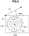
- Fig. 3 is a diagram illustrating how the toner cartridge is replaced in a laser printer with a rotary developing unit illustrated in Fig. 2 .
- the user wants to replace the toner cartridge, the user opens the cover 701.
- the position directly below the opened cover 701 is the replacement position 301 for replacing a toner cartridge.
- the user can change the toner cartridge at the replacement position 301.
- the toner cartridge 730BK can be replaced.
- the toner cartridge replacement position is not limited to the one illustrated in Fig. 3 , but may be different according to the structure of the printing apparatus.
- the motor rotates the developing unit 726 according to a control signal from the printer controller 102 to move any one of cartridges to the replacement position 301.
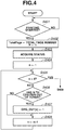
- FIGs. 4 and 5 are flowcharts illustrating a control method according to an exemplary embodiment of the present invention. The control method is performed when the CPU 12 executes a program, which is stored in the ROM 13 and based on the flowcharts in Figs. 4 and 5 .
- step S401 the CPU 12 determines whether to start printing.
- the communication unit 18 receives print data from the computer 100
- the CPU 12 determines that printing is to be started. A case where print data is received from the computer 100 will be described below.
- step S402 the CPU 12 sets a variable TotalPage to a total page number of print data, and sets a variable P to 1.
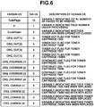
- Fig. 6 illustrates an example of a work area to manage variables to be used in the control method.
- the values of the variables are stored in the RAM 19.
- the variable TotalPage indicates a total number of pages to be printed.
- the P denotes a page number under processing.
- the variable CoverOpen indicates whether the cover 701 has been opened or closed. If the cover 701 has not been opened or closed, 0 (zero) is set. If the cover 701 has been opened or closed, 1 is set. The initial value (default) is 0.
- a variable CRG_OUT serves as a toner-out flag for each toner cartridge. If a toner cartridge is not determined as toner-out, the toner-out flag is set to 0. When the toner cartridge is determined as toner-out, the flag is set to 1. The default value is 0.
- a variable CRG_OVERRIDE serves as a continued use flag for each toner cartridge.
- the continued use means that even when a toner cartridge has been determined as toner out, the user selects continued use.
- a variable CRG_CHANGE indicates whether each toner cartridge has been replaced. If the toner cartridge has not been replaced, 0 is set. If the toner cartridge has been replaced, 1 is set. The default value is 0.
- step S403 the CPU 12 acquires status information from the printing unit 17.
- the status information includes CRG status indicating the remaining amount of toner in each toner cartridge.
- the CPU 12 can detect a toner low state and a toner-out state based on the CRG status.
- step S404 the CPU 12 sets the variable n to 1.
- step S405 the CPU 12 determines whether the value of the variable is larger than 4. If the variable n is equal to or smaller than 4 (NO in step S405), in step S406, the CPU 12 determines whether the n-th toner cartridge is out of toner, according to the status information acquired in step S403.
- the toner cartridge 730C is the first one
- the toner cartridge 730M is the second one
- the toner cartridge 730Y is the third one
- the toner cartridge 730BK is the fourth one.
- step S407 the CPU 12 sets the variable CRG_OUT[n] to 1.
- step S408 the CPU 12 increments the variable n by 1, and the processing proceeds to step S405.
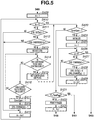
- step S409 the CPU 12 sets a variable m to 1.
- step S410 the CPU 12 determines whether the value of the variable m is larger than 4. If the variable m is equal to or smaller than 4 (NO in step S410) , in step S411, the CPU 12 determines whether the value of CRG_OUT[m] is 1 or not. In other words, the CPU 12 determines whether the m-th toner cartridge has been determined as toner-out.
- step S412 the CPU 12 determines whether the value of CRG_OVERRIDE[m] is 1. In other words, the CPU determines whether continued use of the m-th toner cartridge has already been selected. If the value of CRG_OVERRIDE [m] is 1 (YES in step S412) , the m-th toner cartridge is not replaced. Therefore, the m-th toner cartridge is not moved to the replacement position.
- step S413 the CPU 12 instructs the printing unit 17 to move the m-th toner cartridge to the replacement position. In response to this instruction, the motor in the printing unit 17 moves the m-th toner cartridge to the replacement position.
- step S413 the CPU 12 displays a message on the operation unit prompting that the m-th toner cartridge should be replaced with a new one.
- the CPU 12 sends to the computer 100 status information notifying that the m-th toner cartridge is out of toner.
- the computer 100 displays on the display unit 10 a message indicating that the m-th toner cartridge needs to be replaced.
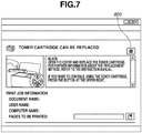
- Fig. 7 is an example message displayed on an operation unit 14 or a CRT display unit 10.
- a message is displayed indicating that a toner cartridge of black needs to be replaced.
- the message may inform that the toner cartridge has run out of toner.
- the operation unit 14 or the CRT display unit 10 displays a button 800 for the user to instruct the continued use of the toner cartridge.
- the computer 100 notifies the printing apparatus 101 whether the button 800 has been pressed.
- the printing apparatus 101 inquires the user if the user is still to make continued use of the toner cartridge.
- step S414 the CPU 12 determines whether the button 800 provided to select continued use has been pressed. If the button 800 has been pressed (YES in step S414), in step S415, the CPU 12 sets CRG_OVERRIDE to 1 for each of one or more toner cartridges whose CRG_OUT is 1. For example, when CRG_OUT[1] and CRG_OUT[4] are 1, CRG_OVERRRIDE[1] and CRG_OVRERRIDE[4] are set to 1.
- the user by a single operation, can select continued use of two or more toner cartridges which have become toner out at the same time.
- the user may separately set continued use for each of two or more toner cartridges that have become toner out at the same time. In this case, after step S415, the processing proceeds to step S419.
- step S416 the CPU 12 determines whether the cover 701 has been opened or closed. If the cover 701 has been opened or closed (YES in step S416), in step S417, the CPU 12 sets the variable CoverOpen to 1 and, in step S418, sets CRG_CHANGE [m] to 1. In the present exemplary embodiment, by detecting the cover 701 being opened or closed, the CPU 12 determines that the toner cartridge has been changed.
- step S419 the CPU 12 increments the value of the variable m by 1, and the processing proceeds to step S410.
- step S420 the CPU 12 determines whether the variable CoverOpen is 1.
- step S421 the CPU 12 determines whether the value of the variable P is larger than the value of the variable TotalPage. If the value of the variable P is larger than the value of the variable TotalPage (YES in step S421), this means that all pages have been printed, and the processing proceeds to step S401.
- step S421 If the value of the variable P is equal to or smaller than the value of the variable TotalPage (NO in step S421), the CPU 12 sends to the printing unit 17 image data of a page number represented by the variable P, in step S422, and the printing unit 17 prints a page of the page number represented by the variable P. In step S423, the CPU 12 increments the variable P by 1 and the processing proceeds to step S403.
- step S424 the CPU 12 instructs the printing unit 17 to perform initialization processing to enable the newly-installed toner cartridge to be used. In step S424, the CPU 12 sets the variable CoverOpen to 0.
- step S425 the CPU 12 sets a variable s to 1.
- step S426 the CPUI 12 determines whether the value s is larger than 4. If the value of the variable s is larger than 4 (YES in step S426), the processing proceeds to step S403. If the value of the variable s is equal to or smaller than 4 (NO in step S426), in step S427, the CPU 12 determines whether the value of CRG_CHANGE[s] is 1.
- step S4208 the CPU 12 sets CRG_OUT[s] to 0, and sets CRG_CHANGE[s] to 0.
- step S429 the CPU 12 increments the variable s by 1 and the processing proceeds to step S426.
- the toner cartridge specified for continued use is not to be a target of replacement thereafter, and the toner cartridge is not to be moved to the replacement position in step S413.
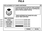
- FIG. 8 illustrates an example of an operation screen displayed on the operation unit 14 or the CRT display unit 10. From among the buttons 801 to 804, the user presses a button corresponding to a toner cartridge the user intends to replace.
- the computer 100 When the user presses a button on the operation screen displayed on the CRT display unit 10, the computer 100 notifies the printing apparatus 101 of an instruction to replace a toner cartridge and the toner cartridge selected by the user.
- the CPU 12 instructs the printing unit 17 to move the toner cartridge selected by the user to the replacement position .
- the motor in the printing unit 17 moves the toner cartridge selected by the user to the replacement position.
- the CPU 12 determines whether the cover 701 has been opened or closed. If the cover 701 has been opened or closed, the CPU 12 sets CRG_OUT corresponding to the toner cartridge selected by the user to 0. Then, the CPU 12 sets CRG_OVERRIDE corresponding to the toner cartridge selected by the user to 0.
- the toner cartridge specified for continued use is not to be a target of replacement thereafter, and is not to be moved to the replacement position in step S413.
- the toner cartridge specified for continued use may be a target of replacement thereafter, and is not to be moved to the replacement position in step S413.
- a user can previously select whether to move the toner cartridge specified for continued use to the replacement position when another toner cartridge runs out of toner.
- Fig. 9 illustrates an example of an operation screen displayed on the operation unit 14 or the CRT display unit 10.
- the user ticks a check box 901 and presses an OK button 902. If the user desires that the toner cartridge specified for continued use should not be moved to the replacement position, the user presses the OK button 902 without ticking the check box 901.
- the CPU 12 sets the variable AUTO to 1 when a check mark is input in the check box 901, and sets the variable AUTO to 0 when a check mark is not input in the check box 901.
- the value of the variable AUTO is stored in the external memory 21 or the hard disks 23.
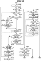
- Fig. 10 is a flowchart illustrating a control method according to the second exemplary embodiment. This control method is performed when the CPU 12 executes a program, which is stored in the ROM 13 and based on the flowchart in Fig. 10 . In Fig. 10 , steps S1001 and S1002 are newly added. The flowchart in Fig. 10 will be described focusing on differences from the flowchart in Fig. 4 .
- step S412 the CPU 12 determines whether the value of CRG_OVERRIDE [m] is 1. If the value of CRG_OVERRIDE is 1 (YES in step S412), in step S1001, the CPU 12 determines whether the value of the variable AUTO is 1.
- step S1002 the CPU 12 determines whether there is another toner cartridge including CRG_OUT having the value of 1 and CRG_OVERRIDE having the value of 0. If there is another toner cartridge (YES in step S1002), in step S413, the CPU 12 moves the m-th toner cartridge to the replacement position.
- the user can select whether to move the toner cartridge specified for continued use to the replacement position when another toner cartridge runs out of toner.
- the second exemplary embodiment it is determined whether to move the toner cartridge specified for continued use to the replacement position when another toner cartridge runs out of toner.
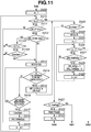
- Fig. 11 is a flowchart illustrating a control method according to the third exemplary embodiment. This control method is implemented when the CPU 12 executes a program, which is stored in the ROM 13 and based on the flowchart in Fig. 11 . In Fig. 11 , steps S1101 and S1102 are added. The flowchart in Fig. 11 will be described focusing on differences from the flowchart in Fig. 4 .
- step S412 the CPU 12 determines whether the value of CRG_OVERRIDE[m] is 1. If the value of CRG_OVERRIDE [m] is 1 (YES in step S412), in step S1101, the CPU 12 determines whether the value of the variable AUTO is 1.
- step S1102 the CPU 12 determines whether the value of the variable CoverOpen is 1. If the value of the variable CoverOpen is 1 (YES in step S1102), in step S413, the CPU 12 moves the m-th toner cartridge to the replacement position.
- the user can select whether to move the toner cartridge specified for continued use to the replacement position when another toner cartridge is replaced.
- a toner cartridge specified for continued use is moved to the replacement position.
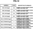
- two variables are provided, namely, a variable CRG_PrintPage representing a number of pages printed by using toner cartridges and a variable CRG_OVERRIDEPage representing a number of pages when continued use of a toner cartridge is specified.
- Fig. 12 is a diagram illustrating an example of a work area in which variables used in the fourth exemplary embodiment are managed. Those values of the variables are stored in the external memory 21 or the hard disk 23.
- the number of pages printed by using the toner cartridge 730C is 100.
- the number of pages printed by using the toner cartridge 730BK is 200. When the number of pages printed by the toner cartridge 730BK was 150, continued use of the toner cartridge 730BK was specified.
- Fig. 13 is a flowchart illustrating a control method according to the fourth exemplary embodiment.
- the control method is implemented when the CPU 12 executes a program, which is stored in the ROM 13 and based on the flowchart of Fig. 13 .
- steps S1301 through S1304 are added.
- the flowchart in Fig. 13 will be described focusing on differences from the flowchart in Fig. 4 .
- step S1301 the CPU 12 increments by 1 the value of CRG_PrintPage corresponding to one or more toner cartridges used in printing in step S422. For example, when the toner cartridge 730BK is used, the CPU increments the value of CRG_PrintPage[4] by 1.
- step S1302 the CPU 12 sets the value of CRG_PrintPage into CRG_OVERRIDEPage with regard to one or more toner cartridges which has been set in step S415. For example, when continued use of the toner cartridge of cyan and the toner cartridge of black is specified, the CPU 12 sets the value of CRG_PrintPage [1]_into CRG_OVERRIDEPage [1]. Furthermore, the CPU 12 sets the value of CRG_PrintPage[4] into CRG_OVERRIDEPage[4].
- step S1303 the CPU 12 determines whether the value of CRG_PrintPage[m] is larger than the value of CRG_OVERRIDEPage[m] with a predetermined value added.
- the predetermined value is 300.
- step S1303 If the value of CRG_PrintPage[m] is larger than the value of CRG_OVERRIDEPage[m] with the predetermined value added (YES in step S1303), the processing proceeds to step S413. If the value of CRG_PrintPage [m] is equal to or smaller than the value of CRG_OVERRIDEPage[m] with the predetermined value added (NO in step S1303), the processing proceeds to step S419.
- step S1304 the CPU 12 sets 0 into each of CRG_PrintPage[s] and CRG_OVERRIDEPage[s].
- the toner cartridge is moved to the replacement position.
- a printing apparatus is not limited to the laser beam printer, but may be printing apparatuses of other printing systems. Though the toner-type printing apparatus has been described above, the present invention can be applied to printing apparatuses by using printing materials, such as ink or toner.
- Moving a storing unit configured to store a recording material to a position where the recording material is supplied to the printing apparatus includes moving a toner cartridge, an ink cartridge or an ink tank to a position where they can be replaced with new ones.
- the above expression further includes moving the toner cartridge to a position where the toner cartridge can be refilled with the toner and moving the ink cartridge to a position where the ink cartridge can be refilled with the ink.
- the CPU 12 executes the program based on the flowcharts in Figs. 4 , 5 , 10 , 11 , and 13 .
- a control circuit may be used, which is designed to execute a control method based on the flowcharts in Figs. 4 , 5 , 10 , 11 , and 12 .
- the user can select whether to move a storing unit determined to have run out of a recording material to a position where the recording material can be replenished.
- the printing apparatus can select whether to move the storing unit determined to have run out of the recording material to the position where the recording material can be replenished.
- aspects of the present invention can also be realized by a computer of a system or apparatus (or devices such as a CPU or MPU) that reads out and executes a program recorded on a memory device to perform the functions of the above-described embodiments, and by a method, the steps of which are performed by a computer of a system or apparatus by, for example, reading out and executing a program recorded on a memory device to perform the functions of the above-described embodiments.
- the program is provided to the computer for example via a network or from a recording medium of various types serving as the memory device (e.g., computer-readable medium).
- the system or apparatus, and the recording medium where the program is stored are included as being within the scope of the present invention.
Landscapes
- Physics & Mathematics (AREA)
- General Physics & Mathematics (AREA)
- Control Or Security For Electrophotography (AREA)
- Accessory Devices And Overall Control Thereof (AREA)
- Color Electrophotography (AREA)
- Dry Development In Electrophotography (AREA)
Description
- The present invention relates to a printing apparatus including a storing unit for storing a recording material, and configured to perform printing by using the recording material.
- In a printing apparatus which rotates a plurality of toner cartridges, when some toner cartridge has run out of toner, this toner cartridge is moved to a position where the user can replace the toner cartridge as discussed in Japanese Patent Application Laid-Open No.
2003-323027 - To move a toner-out cartridge to a position where it can be replaced, the printing apparatus needs to detect a toner-out cartridge. For example, an optical sensor is used to detect remaining amount of toner in a toner cartridge, and when a cartridge that has run out of toner is detected, the cartridge is moved to its replacement position. Thus, the user can replace the toner cartridge smoothly.
- However, if the accuracy of the optical sensor is insufficient, even if a toner cartridge in a toner-out state is detected, some amount of toner often remains in the cartridge enough to print a few pages. There may be some users who still want to use the toner until just before the printed characters are so thin and blurred.
- Despite the fact that the user still wants to keep using the toner cartridge that is determined to be empty, if the user have to move the toner cartridge to the replacement position each time the printing apparatus has determined that the toner cartridge is out of recording material, this is inconvenient for users.
-
JP 2005-250196 -
JP 2007-155762 - According to a first aspect of the present invention, there is provided a printing apparatus as specified in
claim 1. According to a second aspect of the present invention, there is provided a control method for controlling a printing apparatus as specified inclaim 15. According to a third aspect of the present invention, there is provided a computer readable program for controlling a computer of the printing apparatus as specified inclaim 16. - Further features and aspects of the present invention will become apparent from the following detailed description of exemplary embodiments with reference to the attached drawings.
- The accompanying drawings, which are incorporated in and constitute a part of the specification, illustrate exemplary embodiments, features, and aspects of the invention and, together with the description, serve to explain the principles of the invention.
-
Fig. 1 is a block diagram illustrating a printing system according to a first exemplary embodiment of the present invention. -
Fig. 2 is a sectional view of a printing apparatus. -
Fig. 3 is a diagram illustrating how the toner cartridge is replaced in a color laser printer with a rotary developing unit. -
Fig. 4 is a flowchart illustrating a control method according to the first exemplary embodiment of the present invention. -
Fig. 5 is a flowchart illustrating a control method according to the first exemplary embodiment of the present invention. -
Fig. 6 is a diagram illustrating an example of a work area for managing variables. -
Fig. 7 is a diagram illustrating an example of messages displayed on an operation unit or a CRT display unit. -
Fig. 8 is a diagram illustrating an example of an operation screen displayed on the operation unit or the CRT display unit. -
Fig. 9 is a diagram illustrating an example of the operation screen displayed on the operation unit or the CRT display unit. -
Fig. 10 is a flowchart illustrating a control method according to a second embodiment of the present invention. -
Fig. 11 is a flowchart illustrating a control method according to a third embodiment of the present invention. -
Fig. 12 is a diagram illustrating an example of a work area for managing variables used in a fourth embodiment of the present invention. -
Fig. 13 is a flowchart illustrating a control method according to the fourth embodiment of the present invention. - Various exemplary embodiments, features, and aspects of the invention will be described in detail below with reference to the drawings.
-
Fig. 1 is a block diagram illustrating a printing system according to an exemplary embodiment of the present in invention. In this printing system, acomputer 100 communicates with aprinting apparatus 101 through abidirectional interface 24. Thebidirectional interface 24 may be a wired interface, such as LAN or USB, or a wireless LAN. - The
computer 100 includes a central processing unit (CPU) 1, a random access memory (RAM) 2, a read only memory (ROM) 3, asystem bus 4, akeyboard controller 5, a cathode ray tube (CRT)controller 6, amemory controller 7, acommunication unit 8, a keyboard 9, aCRT display 10, and anexternal memory 11. - The
CPU 1 performs various kinds of data processing based on programs stored in a program ROM. TheCPU 1 processes documents including graphics, images, characters, tables (such as spreadsheets) or mixtures of them. TheCPU 1 collectively controls devices connected to thesystem bus 4. Moreover, theCPU 1 develops outline fonts in a RAM for display information, set on theRAM 2, and realizes WYSIWYG (What You See Is What You Get). TheCPU 1 also opens various kinds of windows and executes various kinds of data processing on commands issued by the mouse cursor on theCRT display unit 10. - The
RAM 2 serves as a main memory or a work memory of theCPU 1. TheROM 3 includes a font ROM, a program ROM, and a data ROM. The font ROM stores font data used in document processing. The program ROM stores not only a control program for controlling thecomputer 100 but also stores programs such as a printer selector and a network printer driver. The data ROM stores various kinds of data used in document processing. - The
keyboard controller 5 controls key-in operations from the keyboard 9 and a pointing device (not illustrated). TheCRT controller 6 controls display on theCRT display unit 10. - The
memory controller 7 controls access to theexternal memory 11. Theexternal memory 11 is a memory device to store a boot program, application programs, font data, user files, and edition files. Theexternal memory 11 may be a hard disk, a flash EEPROM memory or a USB memory. - The
communication unit 8 controls communication with theprinting apparatus 101 through thebidirectional interface 24. - The
printing apparatus 101 includes aprinter controller 102, theoperation unit 14, theprinting unit 17, theexternal memory 21, and thehard disk 23. Theprinter controller 102 includes aCPU 12, aROM 13, asystem bus 15, aprinting unit interface 16, acommunication unit 18, aRAM 19, amemory controller 20, and adisk controller 22. - The
CPU 12 executes a control program stored in the program ROM and a control program stored in theexternal memory 21 to perform data processing. In addition, theCPU 12, based on the control program, collectively controls various devices connected to thesystem bus 15. For example, theCPU 12 generates image data, and transmits an image signal based on the image data to theprinting unit 17 through theprinting device 16. - The
CPU 12 transmits a control signal to theprinting unit 17 through theprinting unit interface 16. In addition, theCPU 12 transmits information about theprinting apparatus 101 to thecomputer 100 through thecommunication unit 18. - The
ROM 13 includes the font ROM, the program ROM, and the data ROM. The font ROM stores font data used to generate image data. The program ROM stores a control program which is executed by the CPU12. The data ROM stores various kinds of data to be used in data processing, for example. - The
operation unit 14 is an operation panel including switches and LED displays to display the key input and information. Theoperation unit 14 may be formed by a touch panel. - The
printing unit interface 16 controls communication with theprinting unit 17. Thecommunication unit 18 controls communication with thecomputer 100 performed through thebidirectional interface 24. - The
RAM 19 serves as the main memory and the work memory of theCPU 12. The memory capacity of theRAM 19 can be expanded by adding an optional RAM to an expansion port (not illustrated) . TheRAM 19 can also serve as an image data memory area to store rasterized image data or an environment data memory area to store environment data or a nonvolatile RAM (NVRAM) to store various kinds of parameters. - The
memory controller 20 controls access to theexternal memory 21. Theexternal memory 21, such as an IC card or a USB memory, can store font data, an emulation program, and form data. - The
disk controller 22 controls access to thehard disk 23. Thehard disk 23 stores print data and a control program, for example. -
Fig. 2 is a sectional view of theprinting apparatus 101.Fig. 2 illustrates an internal structure of a color laser printer of a rotary development system. In the present exemplary embodiment, toner is used as a recording material for printing. - A
scanner 711 includes a laser output unit (not illustrated) configured to convert an image signal from theprinter controller 102 into a light signal (laser light), anoctahedral polygon mirror 712, a motor (not illustrated) to rotate thepolygon mirror 712, and an f/θ lens (imaging lens) 713. - The laser beam emitted from the laser output unit is reflected from a side face of the
polygon mirror 712, passes through the f/θ lens 713 and thereflection mirror 714, and thus scans the surface ofphotosensitive drum 715 linearly (raster scan). Thephotosensitive drum 715 rotates in the arrow direction as illustrated inFig. 2 . - In this manner, an electrostatic latent image corresponding to an image represented by an image signal is formed on the surface of the
photosensitive drum 715. Around thephotosensitive drum 715, there are arranged a primary charging unit 717, a wholesurface exposure lamp 718, acleaner unit 723 to collect the toner not transferred to a paper (residual toner), and apre-exposure charger 724. - A developing
unit 726 is a unit to develop the electrostatic latent image formed on the surface of thephotosensitive drum 715. The developingunit 726 includes the following units. Thetoner cartridges -
Development sleeves photosensitive drum 715 to develop the latent images into visible images by the developer.Screws 732 convey the developers from thetoner cartridges development sleeves photosensitive drum 715. - The toner cartridges, the development sleeves, and the screws are disposed around the central axis P. The symbols attached to the components Y, M, C and BK represent different colors. More specifically, C is cyan, M is magenta, Y is yellow, and BK is black.
- A
cover 701 can be opened or closed. The user can open thecover 701 and replace the toner cartridges. The toner cartridge directly below thecover 701 can be dismounted. The position directly below thecover 701 is referred to as a position for replacing toner cartridges. InFig. 2 , the toner cartridge 730BK is at the replacement position. Since thetoner cartridges - A
position sensor 742 detects the rotational position of a developing unit 762 . When a toner image of yellow is formed on thephotosensitive drum 715, the developingunit 726 is rotated about the axis P by a motor (not illustrated) , and thephotosensitive drum 715 and the developing sleeve 731Y are brought into contact with each other. -
Fig. 2 illustrates how the above-described operation is performed. To form a toner image of magenta, the developingunit 726 is rotated about the axis P by the motor, and thephotosensitive drum 715 and thedevelopment sleeve 731M are brought into contact with each other. This operation is similarly performed when toner images of cyan and black are formed. - The
transfer drum 716 transfers the toner image formed on thephotosensitive drum 715 onto a paper sheet. Theactuator plate 719 detects the position of thetransfer drum 716 moved as a result of its movement. Theposition sensor 720 detects, by approaching theactuator plate 719, a fact that thetransfer drum 716 has reached the home position. - There are provided the
actuator plate 719, theposition sensor 720, a transferdrum cleaner unit 725, apaper pressing roller 727, astatic eliminator 728, atransfer charging unit 729, and thetransfer drum 716 around thetransfer drum 716. - The
sheet cassettes paper 791. For example, thesheet cassette 735 contains A4-size sheets and thesheet cassette 736 contains A3-size sheets. When a sheet of paper is fed and conveyed, apaper roller sheet cassette - Timing
rollers rollers paper guide 490. Then, the paper sheet is wound around thetransfer drum 716 with the leading end supported by thegripper 721. Whether thesheet cassette printer controller 102. Only the paper roller, which corresponds to the selected sheet cassette, is rotated. - By the arrangement described above, full color (C, M, Y, and BK) printing is performed.
-
Fig. 3 is a diagram illustrating how the toner cartridge is replaced in a laser printer with a rotary developing unit illustrated inFig. 2 . When the user wants to replace the toner cartridge, the user opens thecover 701. - The position directly below the opened
cover 701 is thereplacement position 301 for replacing a toner cartridge. The user can change the toner cartridge at thereplacement position 301. In the example ofFig. 3 , the toner cartridge 730BK can be replaced. However, the toner cartridge replacement position is not limited to the one illustrated inFig. 3 , but may be different according to the structure of the printing apparatus. - The motor rotates the developing
unit 726 according to a control signal from theprinter controller 102 to move any one of cartridges to thereplacement position 301. - A control method for the printing apparatus according to the present invention will be described.
Figs. 4 and5 are flowcharts illustrating a control method according to an exemplary embodiment of the present invention. The control method is performed when theCPU 12 executes a program, which is stored in theROM 13 and based on the flowcharts inFigs. 4 and5 . - In step S401, the
CPU 12 determines whether to start printing. When thecommunication unit 18 receives print data from thecomputer 100, theCPU 12 determines that printing is to be started. A case where print data is received from thecomputer 100 will be described below. - When print data has been received, in step S402, the
CPU 12 sets a variable TotalPage to a total page number of print data, and sets a variable P to 1. -
Fig. 6 illustrates an example of a work area to manage variables to be used in the control method. The values of the variables are stored in theRAM 19. - The variable TotalPage indicates a total number of pages to be printed. The P denotes a page number under processing. The variable CoverOpen indicates whether the
cover 701 has been opened or closed. If thecover 701 has not been opened or closed, 0 (zero) is set. If thecover 701 has been opened or closed, 1 is set. The initial value (default) is 0. - A variable CRG_OUT serves as a toner-out flag for each toner cartridge. If a toner cartridge is not determined as toner-out, the toner-out flag is set to 0. When the toner cartridge is determined as toner-out, the flag is set to 1. The default value is 0.
- A variable CRG_OVERRIDE serves as a continued use flag for each toner cartridge. The continued use means that even when a toner cartridge has been determined as toner out, the user selects continued use.
- Even when a remaining toner amount sensor detects that the toner cartridge is empty, there may be cases where some toner remains in the toner cartridge. In such a case, the user can still use that small amount of toner by "continued use." If the user does not select continued use, 0 is set in the above variable. If the user selects continued use, 1 is set. The default value is 0.
- A variable CRG_CHANGE indicates whether each toner cartridge has been replaced. If the toner cartridge has not been replaced, 0 is set. If the toner cartridge has been replaced, 1 is set. The default value is 0.
- In step S403, the
CPU 12 acquires status information from theprinting unit 17. The status information includes CRG status indicating the remaining amount of toner in each toner cartridge. TheCPU 12 can detect a toner low state and a toner-out state based on the CRG status. - In step S404, the
CPU 12 sets the variable n to 1. In step S405, theCPU 12 determines whether the value of the variable is larger than 4. If the variable n is equal to or smaller than 4 (NO in step S405), in step S406, theCPU 12 determines whether the n-th toner cartridge is out of toner, according to the status information acquired in step S403. In the example ofFig. 4 , thetoner cartridge 730C is the first one, thetoner cartridge 730M is the second one, thetoner cartridge 730Y is the third one, and the toner cartridge 730BK is the fourth one. - If the n-th toner cartridge is in the toner out state, in step S407, the
CPU 12 sets the variable CRG_OUT[n] to 1. In step S408, theCPU 12 increments the variable n by 1, and the processing proceeds to step S405. - If the variable n is larger than 4 (YES in step S405) , in step S409, the
CPU 12 sets a variable m to 1. In step S410, theCPU 12 determines whether the value of the variable m is larger than 4. If the variable m is equal to or smaller than 4 (NO in step S410) , in step S411, theCPU 12 determines whether the value of CRG_OUT[m] is 1 or not. In other words, theCPU 12 determines whether the m-th toner cartridge has been determined as toner-out. - If CRG_OUT[m] is 1 (YES in step S411), in step S412, the
CPU 12 determines whether the value of CRG_OVERRIDE[m] is 1. In other words, the CPU determines whether continued use of the m-th toner cartridge has already been selected. If the value of CRG_OVERRIDE [m] is 1 (YES in step S412) , the m-th toner cartridge is not replaced. Therefore, the m-th toner cartridge is not moved to the replacement position. - If the value of CRG_OVERRIDE[m] is not 1 (NO in step S412), in step S413, the
CPU 12 instructs theprinting unit 17 to move the m-th toner cartridge to the replacement position. In response to this instruction, the motor in theprinting unit 17 moves the m-th toner cartridge to the replacement position. - In step S413, the
CPU 12 displays a message on the operation unit prompting that the m-th toner cartridge should be replaced with a new one. Alternatively, through thecommunication unit 18, theCPU 12 sends to thecomputer 100 status information notifying that the m-th toner cartridge is out of toner. Thecomputer 100 displays on the display unit 10 a message indicating that the m-th toner cartridge needs to be replaced. -
Fig. 7 is an example message displayed on anoperation unit 14 or aCRT display unit 10. In the example ofFig. 7 , a message is displayed indicating that a toner cartridge of black needs to be replaced. The message may inform that the toner cartridge has run out of toner. - Together with the display of a message about necessity of toner cartridge replacement, the
operation unit 14 or theCRT display unit 10 displays abutton 800 for the user to instruct the continued use of the toner cartridge. Thecomputer 100 notifies theprinting apparatus 101 whether thebutton 800 has been pressed. - There may be cases where printed characters or graphics may be too thin and blurred even though the toner cartridge is used continuously, because the toner remains little or has been consumed complexly. Therefore, the
printing apparatus 101 inquires the user if the user is still to make continued use of the toner cartridge. - In step S414, the
CPU 12 determines whether thebutton 800 provided to select continued use has been pressed. If thebutton 800 has been pressed (YES in step S414), in step S415, theCPU 12 sets CRG_OVERRIDE to 1 for each of one or more toner cartridges whose CRG_OUT is 1. For example, when CRG_OUT[1] and CRG_OUT[4] are 1, CRG_OVERRRIDE[1] and CRG_OVRERRIDE[4] are set to 1. - In the example of
Fig. 4 , the user, by a single operation, can select continued use of two or more toner cartridges which have become toner out at the same time. However, the user may separately set continued use for each of two or more toner cartridges that have become toner out at the same time. In this case, after step S415, the processing proceeds to step S419. - If the
button 800 is not pressed (NO in step S414), in step S416, theCPU 12 determines whether thecover 701 has been opened or closed. If thecover 701 has been opened or closed (YES in step S416), in step S417, theCPU 12 sets the variable CoverOpen to 1 and, in step S418, sets CRG_CHANGE [m] to 1. In the present exemplary embodiment, by detecting thecover 701 being opened or closed, theCPU 12 determines that the toner cartridge has been changed. - In step S419, the
CPU 12 increments the value of the variable m by 1, and the processing proceeds to step S410. - If the variable m is larger than 4 (YES in step S410), in step S420, the
CPU 12 determines whether the variable CoverOpen is 1. - If the variable CoverOpen is not 1 (NO in step S420), in step S421, the
CPU 12 determines whether the value of the variable P is larger than the value of the variable TotalPage. If the value of the variable P is larger than the value of the variable TotalPage (YES in step S421), this means that all pages have been printed, and the processing proceeds to step S401. - If the value of the variable P is equal to or smaller than the value of the variable TotalPage (NO in step S421), the
CPU 12 sends to theprinting unit 17 image data of a page number represented by the variable P, in step S422, and theprinting unit 17 prints a page of the page number represented by the variable P. In step S423, theCPU 12 increments the variable P by 1 and the processing proceeds to step S403. - If the value of the variable CoverOpen is 1 (YES in step S420), in step S424, the
CPU 12 instructs theprinting unit 17 to perform initialization processing to enable the newly-installed toner cartridge to be used. In step S424, theCPU 12 sets the variable CoverOpen to 0. - In step S425, the
CPU 12 sets a variable s to 1. In step S426, theCPUI 12 determines whether the value s is larger than 4. If the value of the variable s is larger than 4 (YES in step S426), the processing proceeds to step S403. If the value of the variable s is equal to or smaller than 4 (NO in step S426), in step S427, theCPU 12 determines whether the value of CRG_CHANGE[s] is 1. - If the value of CRG_CHANGE[s] is 1 (YES in step S427), in step S428, the
CPU 12 sets CRG_OUT[s] to 0, and sets CRG_CHANGE[s] to 0. - In step S429, the
CPU 12 increments the variable s by 1 and the processing proceeds to step S426. - According to the control method illustrated in
Figs. 4 and5 , the toner cartridge specified for continued use is not to be a target of replacement thereafter, and the toner cartridge is not to be moved to the replacement position in step S413. - When the user intends to replace the toner cartridge specified for continued use, the user have to separately issue an instruction to replace the toner cartridge.
Fig. 8 illustrates an example of an operation screen displayed on theoperation unit 14 or theCRT display unit 10. From among thebuttons 801 to 804, the user presses a button corresponding to a toner cartridge the user intends to replace. - When the user presses a button on the operation screen displayed on the
CRT display unit 10, thecomputer 100 notifies theprinting apparatus 101 of an instruction to replace a toner cartridge and the toner cartridge selected by the user. - The
CPU 12 instructs theprinting unit 17 to move the toner cartridge selected by the user to the replacement position . In response to the instruction, the motor in theprinting unit 17 moves the toner cartridge selected by the user to the replacement position. Then, theCPU 12 determines whether thecover 701 has been opened or closed. If thecover 701 has been opened or closed, theCPU 12 sets CRG_OUT corresponding to the toner cartridge selected by the user to 0. Then, theCPU 12 sets CRG_OVERRIDE corresponding to the toner cartridge selected by the user to 0. - In the exemplary embodiment in
Fig. 5 , the toner cartridge specified for continued use is not to be a target of replacement thereafter, and is not to be moved to the replacement position in step S413. However, there may be some users who want to replace the toner cartridge specified for continued use at a timing when another toner cartridge runs out of toner, together therewith. - For this reason, according to a second exemplary embodiment of the present invention, a user can previously select whether to move the toner cartridge specified for continued use to the replacement position when another toner cartridge runs out of toner.
-
Fig. 9 illustrates an example of an operation screen displayed on theoperation unit 14 or theCRT display unit 10. When the user desires that the toner cartridge specified for continued use should be moved to the replacement position in a case where another toner cartridge runs out of toner, the user ticks acheck box 901 and presses anOK button 902. If the user desires that the toner cartridge specified for continued use should not be moved to the replacement position, the user presses theOK button 902 without ticking thecheck box 901. - The
CPU 12 sets the variable AUTO to 1 when a check mark is input in thecheck box 901, and sets the variable AUTO to 0 when a check mark is not input in thecheck box 901. The value of the variable AUTO is stored in theexternal memory 21 or thehard disks 23. -
Fig. 10 is a flowchart illustrating a control method according to the second exemplary embodiment. This control method is performed when theCPU 12 executes a program, which is stored in theROM 13 and based on the flowchart inFig. 10 . InFig. 10 , steps S1001 and S1002 are newly added. The flowchart inFig. 10 will be described focusing on differences from the flowchart inFig. 4 . - In step S412, the
CPU 12 determines whether the value of CRG_OVERRIDE [m] is 1. If the value of CRG_OVERRIDE is 1 (YES in step S412), in step S1001, theCPU 12 determines whether the value of the variable AUTO is 1. - If the value of the variable AUTO is 1, the
CPU 12 refers to CRG_OUT[1] through CRG_OUT[4], and CRG_OVERRIDE[1] through CRG_OVERRIDE[4] . In step S1002, theCPU 12 determines whether there is another toner cartridge including CRG_OUT having the value of 1 and CRG_OVERRIDE having the value of 0. If there is another toner cartridge (YES in step S1002), in step S413, theCPU 12 moves the m-th toner cartridge to the replacement position. - According to the second exemplary embodiment, the user can select whether to move the toner cartridge specified for continued use to the replacement position when another toner cartridge runs out of toner.
- According to the second exemplary embodiment, it is determined whether to move the toner cartridge specified for continued use to the replacement position when another toner cartridge runs out of toner. In a third exemplary embodiment of the present invention, it is determined whether to move the toner cartridge specified for continued use to the replacement position when another toner cartridge is replaced.
-
Fig. 11 is a flowchart illustrating a control method according to the third exemplary embodiment. This control method is implemented when theCPU 12 executes a program, which is stored in theROM 13 and based on the flowchart inFig. 11 . InFig. 11 , steps S1101 and S1102 are added. The flowchart inFig. 11 will be described focusing on differences from the flowchart inFig. 4 . - In step S412, the
CPU 12 determines whether the value of CRG_OVERRIDE[m] is 1. If the value of CRG_OVERRIDE [m] is 1 (YES in step S412), in step S1101, theCPU 12 determines whether the value of the variable AUTO is 1. - If the value of the variable AUTO is 1 (YES in step S1101), in step S1102, the
CPU 12 determines whether the value of the variable CoverOpen is 1. If the value of the variable CoverOpen is 1 (YES in step S1102), in step S413, theCPU 12 moves the m-th toner cartridge to the replacement position. - According to the third exemplary embodiment, the user can select whether to move the toner cartridge specified for continued use to the replacement position when another toner cartridge is replaced.
- According to a fourth exemplary embodiment, after continued use of a toner cartridge is specified and then a predetermined number of pages are printed, a toner cartridge specified for continued use is moved to the replacement position. In the fourth exemplary embodiment, two variables are provided, namely, a variable CRG_PrintPage representing a number of pages printed by using toner cartridges and a variable CRG_OVERRIDEPage representing a number of pages when continued use of a toner cartridge is specified.
-
Fig. 12 is a diagram illustrating an example of a work area in which variables used in the fourth exemplary embodiment are managed. Those values of the variables are stored in theexternal memory 21 or thehard disk 23. In the example ofFig. 12 , the number of pages printed by using thetoner cartridge 730C is 100. The number of pages printed by using the toner cartridge 730BK is 200. When the number of pages printed by the toner cartridge 730BK was 150, continued use of the toner cartridge 730BK was specified. -
Fig. 13 is a flowchart illustrating a control method according to the fourth exemplary embodiment. The control method is implemented when theCPU 12 executes a program, which is stored in theROM 13 and based on the flowchart ofFig. 13 . InFig. 13 , steps S1301 through S1304 are added. The flowchart inFig. 13 will be described focusing on differences from the flowchart inFig. 4 . - After executing step S422, in step S1301, the
CPU 12 increments by 1 the value of CRG_PrintPage corresponding to one or more toner cartridges used in printing in step S422. For example, when the toner cartridge 730BK is used, the CPU increments the value of CRG_PrintPage[4] by 1. - After executing step S415, in step S1302, the
CPU 12 sets the value of CRG_PrintPage into CRG_OVERRIDEPage with regard to one or more toner cartridges which has been set in step S415. For example, when continued use of the toner cartridge of cyan and the toner cartridge of black is specified, theCPU 12 sets the value of CRG_PrintPage [1]_into CRG_OVERRIDEPage [1]. Furthermore, theCPU 12 sets the value of CRG_PrintPage[4] into CRG_OVERRIDEPage[4]. - If the value of CRG_OVERRIDE [m] is 1 (YES in step S412), in step S1303, the
CPU 12 determines whether the value of CRG_PrintPage[m] is larger than the value of CRG_OVERRIDEPage[m] with a predetermined value added. In the example ofFig. 13 , the predetermined value is 300. - If the value of CRG_PrintPage[m] is larger than the value of CRG_OVERRIDEPage[m] with the predetermined value added (YES in step S1303), the processing proceeds to step S413. If the value of CRG_PrintPage [m] is equal to or smaller than the value of CRG_OVERRIDEPage[m] with the predetermined value added (NO in step S1303), the processing proceeds to step S419.
- After executing step S428, in step S1304, the
CPU 12sets 0 into each of CRG_PrintPage[s] and CRG_OVERRIDEPage[s]. - According to the fourth exemplary embodiment, even when continued use of the toner cartridge has been specified, after a predetermined number of pages are printed, the toner cartridge is moved to the replacement position.
- A printing apparatus according to the present invention is not limited to the laser beam printer, but may be printing apparatuses of other printing systems. Though the toner-type printing apparatus has been described above, the present invention can be applied to printing apparatuses by using printing materials, such as ink or toner.
- Moving a storing unit configured to store a recording material to a position where the recording material is supplied to the printing apparatus includes moving a toner cartridge, an ink cartridge or an ink tank to a position where they can be replaced with new ones. The above expression further includes moving the toner cartridge to a position where the toner cartridge can be refilled with the toner and moving the ink cartridge to a position where the ink cartridge can be refilled with the ink.
- In the above-described exemplary embodiments, the
CPU 12 executes the program based on the flowcharts inFigs. 4 ,5 ,10 ,11 , and13 . However, instead of theCPU 12, a control circuit may be used, which is designed to execute a control method based on the flowcharts inFigs. 4 ,5 ,10 ,11 , and12 . - According to the present invention, the user can select whether to move a storing unit determined to have run out of a recording material to a position where the recording material can be replenished. The printing apparatus can select whether to move the storing unit determined to have run out of the recording material to the position where the recording material can be replenished.
- Aspects of the present invention can also be realized by a computer of a system or apparatus (or devices such as a CPU or MPU) that reads out and executes a program recorded on a memory device to perform the functions of the above-described embodiments, and by a method, the steps of which are performed by a computer of a system or apparatus by, for example, reading out and executing a program recorded on a memory device to perform the functions of the above-described embodiments. For this purpose, the program is provided to the computer for example via a network or from a recording medium of various types serving as the memory device (e.g., computer-readable medium). In such a case, the system or apparatus, and the recording medium where the program is stored, are included as being within the scope of the present invention.
- While the present invention has been described with reference to exemplary embodiments, it is to be understood that the invention is limited by the scope of the following claims.
Claims (16)
- A printing apparatus (101) configured to perform printing by using a recording material stored in storing means (730Y, 730M, 730C, 730BK), comprising:moving means configured to move the storing means (730Y, 730M, 730C, 730BK) to a position where a recording material is supplied to the printing apparatus (101);control means (12) configured to cause the moving means to move the storing means (730Y, 730M, 730C, 730BK) to the position, according to a determination that the storing means (730Y, 730M, 730C, 730BK) has run low on the recording material or has run out of the recording material; andsetting means configured to set continued use of the storing means (730Y, 730M, 730C, 730BK) determined to have run low on the recording material or run out of the recording material, according to an instruction (800) from a user via a first screen displaying a message about necessity of a replacement of the storing means,wherein the control means (12) does not cause the moving means to move the storing means (730Y, 730M, 730C, 730BK) to the position even when the storing means (730Y, 730M, 730C, 730BK) is determined to have run low on the recording material or run out of the recording material if continued use of the storing means (730Y, 730M, 730C, 730BK) determined to have run low on the recording material or run out of the recording material is set,wherein, even if continued use of the storing means (730Y, 730M, 730C, 730BK) determined to have run low on the recording material or run out of the recording material is set, the control means is further configured to cause the moving means to move the storing means (730Y, 730M, 730C, 730BK) to the position according to another instruction from the user via a second screen.
- The printing apparatus (101) according to claim 1, further comprising:selecting means configured to select whether to move first storing means determined to have run low on the recording material or run out of the recording material to the position when second storing means different from the first storing means is determined to have run low on the recording material or run out of the recording material,wherein when moving the first storing means to the position is selected and the second storing means is determined to have run low on the recording material or run out of the recording material, the moving means moves both the first storing means and the second storing means to the position.
- The printing apparatus (101) according to claim 2, wherein when moving the first storing means to the position is not selected and the second storing means is determined to have run low on the recording material or run out of the recoding material, the moving means does not move the first storing means to the position, but moves the second storing means to the position.
- The printing apparatus (101) according to claim 1, wherein after continued use of the storing means (730Y, 730M, 730C, 730BK) determined to have run low on the recording material or run out of the recording material is set, when a number of pages printed by using the storing means (730Y, 730M, 730C, 730BK) reaches a predetermined number, the control means causes the moving means to move the storing means (730Y, 730M, 730C, 730BK) to the position.
- The printing apparatus (101) according to claim 1, wherein the recording material is toner and the storing means is a toner cartridge (730Y, 730M, 730C, 730BK).
- The printing apparatus (101) according to claim 1, wherein the moving means rotates a plurality of storing means (730Y, 730M, 730C, 730BK) and moves storing means (730Y, 730M, 730C, 730BK) determined to have run low on the recording material or run out of the recording material to the position.
- The printing apparatus (101) according to claim 1, wherein supplying the recording material to the printing apparatus (101) includes replacing the storing means (730Y, 730M, 730C, 730BK).
- The printing apparatus (101) according to claim 1, wherein supplying the recording material to the printing apparatus (101) includes refilling the storing means (730Y, 730M, 730C, 730BK) with the recording material.
- The printing apparatus (101) according to claim 1, further comprising:
a communication unit (18) for receiving the instruction from the user through an external computer (100). - The printing apparatus (101) according to claim 1, wherein the position where a recording material is supplied to the printing apparatus (101) is a position corresponding to a cover (701) which can be opened or closed.
- The printing apparatus (101) according to claim 10, wherein the control means (12) is further configured to cause the moving means to move first storing means determined to have run low on or have run out of the recording material to the position, and to cause the moving means to move second storing means determined to have run low on or have run out of the recording material to the position according to the cover (701) being closed after the first storing means is moved to the position.
- The printing apparatus (101) according to claim 10, wherein the control means (12) is configured to cause the moving means to move the storing means (730Y, 730M, 730C, 730BK), according to the determination that the storing means (730Y, 730M, 730C, 730BK) has run low on or has run out of the recording material.
- The printing apparatus (101) according to claim 10, wherein the setting means is further configured, according to an instruction from the user, to move the storing means, the continued use of which has been set, to the position if another storing means is determined to have run low on or to have run out of the recording material.
- The printing apparatus (101) according to claim 1, further comprising memory means configured to store information indicating whether or not each of a plurality of storing means (730Y, 730M, 730C, 730BK) is determined to have run low on the recording material or to have run out of the recording material and information indicating whether or not to continue to use each of the plurality of storing means (730Y, 730M, 730C, 730BK) is set.
- A control method for a printing apparatus (101) that performs printing by using a recording material stored in storing means (730Y, 730M, 730C, 730BK), comprising:moving the storing means (730Y, 730M, 730C, 730BK) to a position where a recording material is supplied to the printing apparatus (101), according to a determination that the storing means has run low on the recording material or has run out of the recording material; andsetting continued use of the storing means (730Y, 730M, 730C, 730BK) determined to have run low on the recording material or run out of the recording material, according to an instruction (800) from a user via a first screen displaying a message about necessity of a replacement of the storing means,wherein the storing means (730Y, 730M, 730C, 730BK) is not moved to the position even when the storing means (730Y, 730M, 730C, 730BK) is determined to have run out of the recording material if continued use of the storing means (730Y, 730M, 730C, 730BK) determined to have run low on the recording material or run out of the recording material is set,wherein, even if continued use of the storing means (730Y, 730M, 730C, 730BK) determined to have run low on the recording material or run out of the recording material is set, causing the moving to move the storing means (730Y, 730M, 730C, 730BK) to the position according to another instruction from the user via a second screen.
- A computer-readable program for causing a computer of a printing apparatus (101) that performs printing by using the recording material stored in storing means (730Y, 730M, 730C, 730BK), to execute the method of claim 15.
Applications Claiming Priority (1)
| Application Number | Priority Date | Filing Date | Title |
|---|---|---|---|
| JP2011159012A JP5864932B2 (en) | 2011-07-20 | 2011-07-20 | Printing apparatus, printing apparatus control method, and program |
Publications (3)
| Publication Number | Publication Date |
|---|---|
| EP2549333A2 EP2549333A2 (en) | 2013-01-23 |
| EP2549333A3 EP2549333A3 (en) | 2013-12-18 |
| EP2549333B1 true EP2549333B1 (en) | 2019-05-08 |
Family
ID=46798997
Family Applications (1)
| Application Number | Title | Priority Date | Filing Date |
|---|---|---|---|
| EP12176725.5A Active EP2549333B1 (en) | 2011-07-20 | 2012-07-17 | Printing apparatus, control method for the printing apparatus and program |
Country Status (5)
| Country | Link |
|---|---|
| US (1) | US8913268B2 (en) |
| EP (1) | EP2549333B1 (en) |
| JP (1) | JP5864932B2 (en) |
| KR (1) | KR101549289B1 (en) |
| CN (1) | CN102886996B (en) |
Families Citing this family (3)
| Publication number | Priority date | Publication date | Assignee | Title |
|---|---|---|---|---|
| JP6184259B2 (en) * | 2013-09-05 | 2017-08-23 | キヤノン株式会社 | Image forming apparatus |
| JP6677578B2 (en) * | 2016-06-08 | 2020-04-08 | シャープ株式会社 | Image forming device |
| KR102656645B1 (en) * | 2023-11-24 | 2024-04-11 | 주식회사 제이에이치디지털오에이 | color multifunction printer structure |
Citations (1)
| Publication number | Priority date | Publication date | Assignee | Title |
|---|---|---|---|---|
| JP2007155762A (en) * | 2005-11-30 | 2007-06-21 | Fuji Xerox Co Ltd | Image forming apparatus |
Family Cites Families (20)
| Publication number | Priority date | Publication date | Assignee | Title |
|---|---|---|---|---|
| JP2644511B2 (en) * | 1987-12-22 | 1997-08-25 | 株式会社リコー | Image forming device |
| JP3468474B2 (en) * | 1994-04-20 | 2003-11-17 | 株式会社リコー | Image forming device |
| JPH08137175A (en) * | 1994-11-11 | 1996-05-31 | Minolta Co Ltd | Image forming device |
| US5706037A (en) * | 1995-09-28 | 1998-01-06 | Xerox Corporation | System and method for overriding a low marking material status in a facsimile environment |
| JP2003323027A (en) * | 2002-04-26 | 2003-11-14 | Canon Inc | Image processing device, its control method, control program and storage medium |
| KR100484155B1 (en) * | 2002-09-02 | 2005-04-19 | 삼성전자주식회사 | Color printing method for inkjet printer |
| JP2004125960A (en) * | 2002-09-30 | 2004-04-22 | Seiko Epson Corp | Printer |
| JP2004271956A (en) | 2003-03-10 | 2004-09-30 | Canon Inc | Image forming apparatus |
| JP2005242039A (en) * | 2004-02-27 | 2005-09-08 | Kyocera Mita Corp | Image recorder |
| JP2005242040A (en) * | 2004-02-27 | 2005-09-08 | Kyocera Mita Corp | Image recorder |
| US7209672B2 (en) | 2004-03-05 | 2007-04-24 | Seiko Epson Corporation | Image forming apparatus and an image forming method |
| JP2005250196A (en) * | 2004-03-05 | 2005-09-15 | Seiko Epson Corp | Image forming apparatus and image forming method |
| US7330672B2 (en) | 2004-05-17 | 2008-02-12 | Fuji Xerox Co., Ltd. | Image forming apparatus able to execute selected operating mode upon replacement of replaceable unit, and method therefore |
| US7444089B2 (en) * | 2006-02-28 | 2008-10-28 | Kabushiki Kaisha Toshiba | Image forming apparatus, toner cartridge and method to detect toner level |
| JP2008197189A (en) * | 2007-02-09 | 2008-08-28 | Kyocera Mita Corp | Image forming apparatus |
| JP2008276147A (en) | 2007-04-02 | 2008-11-13 | Seiko Epson Corp | Developing device, image forming apparatus, and image forming system |
| CN201109241Y (en) | 2007-11-06 | 2008-09-03 | 珠海天威技术开发有限公司 | Cartridge chip and cartridge |
| US7970295B2 (en) * | 2008-01-28 | 2011-06-28 | Xerox Corporation | Document processing system and method for adjustable print consumable refill level |
| JP5223388B2 (en) | 2008-03-12 | 2013-06-26 | 株式会社リコー | Image forming apparatus, image forming method, and program |
| JP5656449B2 (en) * | 2010-05-11 | 2015-01-21 | キヤノン株式会社 | Printing apparatus and control method performed in printing apparatus |
-
2011
- 2011-07-20 JP JP2011159012A patent/JP5864932B2/en active Active
-
2012
- 2012-07-17 EP EP12176725.5A patent/EP2549333B1/en active Active
- 2012-07-17 US US13/551,364 patent/US8913268B2/en active Active
- 2012-07-18 CN CN201210249453.9A patent/CN102886996B/en active Active
- 2012-07-19 KR KR1020120078708A patent/KR101549289B1/en active IP Right Grant
Patent Citations (1)
| Publication number | Priority date | Publication date | Assignee | Title |
|---|---|---|---|---|
| JP2007155762A (en) * | 2005-11-30 | 2007-06-21 | Fuji Xerox Co Ltd | Image forming apparatus |
Also Published As
| Publication number | Publication date |
|---|---|
| JP5864932B2 (en) | 2016-02-17 |
| EP2549333A3 (en) | 2013-12-18 |
| EP2549333A2 (en) | 2013-01-23 |
| JP2013025030A (en) | 2013-02-04 |
| US8913268B2 (en) | 2014-12-16 |
| US20130021619A1 (en) | 2013-01-24 |
| CN102886996A (en) | 2013-01-23 |
| CN102886996B (en) | 2016-04-13 |
| KR20130011956A (en) | 2013-01-30 |
| KR101549289B1 (en) | 2015-09-01 |
Similar Documents
| Publication | Publication Date | Title |
|---|---|---|
| US9348546B2 (en) | Image forming apparatus, image forming method, and image forming system with rewritable print and permanent print function | |
| US8874939B2 (en) | Apparatus and method for controlling power consumption using printer settings | |
| US20020131086A1 (en) | Information processing apparatus, print control method therefor, and storage medium | |
| US20050168764A1 (en) | Data processor, data processing method, storage medium for storing computer-readable program, and program | |
| EP2549333B1 (en) | Printing apparatus, control method for the printing apparatus and program | |
| CN108508722A (en) | Image forming apparatus | |
| KR101320142B1 (en) | Printing apparatus, control method therefor and a computer readable storage medium for same | |
| US8942578B2 (en) | Printing apparatus, information processing apparatus, and control method for printing apparatus and information processing apparatus | |
| US7456984B2 (en) | Billing control in print system | |
| KR101502201B1 (en) | Printing apparatus and control method for printing apparatus | |
| US20140168699A1 (en) | Printing system, printing apparatus, information processing apparatus, and printing control method | |
| JP2012027310A (en) | Image formation device | |
| CN102289167B (en) | Image forming apparatus and method for controlling same | |
| JP2003323027A (en) | Image processing device, its control method, control program and storage medium | |
| JP6707411B2 (en) | Image forming method and image forming apparatus | |
| KR101279070B1 (en) | Method of printing images continuously even when toner is completely consumed | |
| JP2006302036A (en) | Color processing mode switching method, information processor implementing the method, and control program thereof | |
| JP7187921B2 (en) | Print control device and program | |
| CN106476446B (en) | Printing apparatus and control method for printing apparatus | |
| KR100509461B1 (en) | Method for indicating residual toner | |
| US20180183943A1 (en) | Image forming device and image forming method | |
| JP2024048799A (en) | Image forming apparatus and control method thereof | |
| JP2010072660A (en) | Image forming apparatus |
Legal Events
| Date | Code | Title | Description |
|---|---|---|---|
| PUAI | Public reference made under article 153(3) epc to a published international application that has entered the european phase |
Free format text: ORIGINAL CODE: 0009012 |
|
| AK | Designated contracting states |
Kind code of ref document: A2 Designated state(s): AL AT BE BG CH CY CZ DE DK EE ES FI FR GB GR HR HU IE IS IT LI LT LU LV MC MK MT NL NO PL PT RO RS SE SI SK SM TR |
|
| AX | Request for extension of the european patent |
Extension state: BA ME |
|
| PUAL | Search report despatched |
Free format text: ORIGINAL CODE: 0009013 |
|
| AK | Designated contracting states |
Kind code of ref document: A3 Designated state(s): AL AT BE BG CH CY CZ DE DK EE ES FI FR GB GR HR HU IE IS IT LI LT LU LV MC MK MT NL NO PL PT RO RS SE SI SK SM TR |
|
| AX | Request for extension of the european patent |
Extension state: BA ME |
|
| RIC1 | Information provided on ipc code assigned before grant |
Ipc: G03G 15/00 20060101AFI20131111BHEP |
|
| 17P | Request for examination filed |
Effective date: 20140318 |
|
| RBV | Designated contracting states (corrected) |
Designated state(s): AL AT BE BG CH CY CZ DE DK EE ES FI FR GB GR HR HU IE IS IT LI LT LU LV MC MK MT NL NO PL PT RO RS SE SI SK SM TR |
|
| STAA | Information on the status of an ep patent application or granted ep patent |
Free format text: STATUS: EXAMINATION IS IN PROGRESS |
|
| 17Q | First examination report despatched |
Effective date: 20171201 |
|
| GRAP | Despatch of communication of intention to grant a patent |
Free format text: ORIGINAL CODE: EPIDOSNIGR1 |
|
| STAA | Information on the status of an ep patent application or granted ep patent |
Free format text: STATUS: GRANT OF PATENT IS INTENDED |
|
| INTG | Intention to grant announced |
Effective date: 20181219 |
|
| GRAS | Grant fee paid |
Free format text: ORIGINAL CODE: EPIDOSNIGR3 |
|
| GRAA | (expected) grant |
Free format text: ORIGINAL CODE: 0009210 |
|
| STAA | Information on the status of an ep patent application or granted ep patent |
Free format text: STATUS: THE PATENT HAS BEEN GRANTED |
|
| AK | Designated contracting states |
Kind code of ref document: B1 Designated state(s): AL AT BE BG CH CY CZ DE DK EE ES FI FR GB GR HR HU IE IS IT LI LT LU LV MC MK MT NL NO PL PT RO RS SE SI SK SM TR |
|
| REG | Reference to a national code |
Ref country code: GB Ref legal event code: FG4D |
|
| REG | Reference to a national code |
Ref country code: CH Ref legal event code: EP Ref country code: AT Ref legal event code: REF Ref document number: 1131133 Country of ref document: AT Kind code of ref document: T Effective date: 20190515 |
|
| REG | Reference to a national code |
Ref country code: DE Ref legal event code: R096 Ref document number: 602012059786 Country of ref document: DE |
|
| REG | Reference to a national code |
Ref country code: IE Ref legal event code: FG4D |
|
| REG | Reference to a national code |
Ref country code: NL Ref legal event code: MP Effective date: 20190508 |
|
| REG | Reference to a national code |
Ref country code: LT Ref legal event code: MG4D |
|
| PG25 | Lapsed in a contracting state [announced via postgrant information from national office to epo] |
Ref country code: AL Free format text: LAPSE BECAUSE OF FAILURE TO SUBMIT A TRANSLATION OF THE DESCRIPTION OR TO PAY THE FEE WITHIN THE PRESCRIBED TIME-LIMIT Effective date: 20190508 Ref country code: PT Free format text: LAPSE BECAUSE OF FAILURE TO SUBMIT A TRANSLATION OF THE DESCRIPTION OR TO PAY THE FEE WITHIN THE PRESCRIBED TIME-LIMIT Effective date: 20190908 Ref country code: ES Free format text: LAPSE BECAUSE OF FAILURE TO SUBMIT A TRANSLATION OF THE DESCRIPTION OR TO PAY THE FEE WITHIN THE PRESCRIBED TIME-LIMIT Effective date: 20190508 Ref country code: SE Free format text: LAPSE BECAUSE OF FAILURE TO SUBMIT A TRANSLATION OF THE DESCRIPTION OR TO PAY THE FEE WITHIN THE PRESCRIBED TIME-LIMIT Effective date: 20190508 Ref country code: HR Free format text: LAPSE BECAUSE OF FAILURE TO SUBMIT A TRANSLATION OF THE DESCRIPTION OR TO PAY THE FEE WITHIN THE PRESCRIBED TIME-LIMIT Effective date: 20190508 Ref country code: NO Free format text: LAPSE BECAUSE OF FAILURE TO SUBMIT A TRANSLATION OF THE DESCRIPTION OR TO PAY THE FEE WITHIN THE PRESCRIBED TIME-LIMIT Effective date: 20190808 Ref country code: LT Free format text: LAPSE BECAUSE OF FAILURE TO SUBMIT A TRANSLATION OF THE DESCRIPTION OR TO PAY THE FEE WITHIN THE PRESCRIBED TIME-LIMIT Effective date: 20190508 Ref country code: FI Free format text: LAPSE BECAUSE OF FAILURE TO SUBMIT A TRANSLATION OF THE DESCRIPTION OR TO PAY THE FEE WITHIN THE PRESCRIBED TIME-LIMIT Effective date: 20190508 Ref country code: NL Free format text: LAPSE BECAUSE OF FAILURE TO SUBMIT A TRANSLATION OF THE DESCRIPTION OR TO PAY THE FEE WITHIN THE PRESCRIBED TIME-LIMIT Effective date: 20190508 |
|
| PG25 | Lapsed in a contracting state [announced via postgrant information from national office to epo] |
Ref country code: RS Free format text: LAPSE BECAUSE OF FAILURE TO SUBMIT A TRANSLATION OF THE DESCRIPTION OR TO PAY THE FEE WITHIN THE PRESCRIBED TIME-LIMIT Effective date: 20190508 Ref country code: LV Free format text: LAPSE BECAUSE OF FAILURE TO SUBMIT A TRANSLATION OF THE DESCRIPTION OR TO PAY THE FEE WITHIN THE PRESCRIBED TIME-LIMIT Effective date: 20190508 Ref country code: BG Free format text: LAPSE BECAUSE OF FAILURE TO SUBMIT A TRANSLATION OF THE DESCRIPTION OR TO PAY THE FEE WITHIN THE PRESCRIBED TIME-LIMIT Effective date: 20190808 Ref country code: GR Free format text: LAPSE BECAUSE OF FAILURE TO SUBMIT A TRANSLATION OF THE DESCRIPTION OR TO PAY THE FEE WITHIN THE PRESCRIBED TIME-LIMIT Effective date: 20190809 |
|
| REG | Reference to a national code |
Ref country code: AT Ref legal event code: MK05 Ref document number: 1131133 Country of ref document: AT Kind code of ref document: T Effective date: 20190508 |
|
| PG25 | Lapsed in a contracting state [announced via postgrant information from national office to epo] |
Ref country code: AT Free format text: LAPSE BECAUSE OF FAILURE TO SUBMIT A TRANSLATION OF THE DESCRIPTION OR TO PAY THE FEE WITHIN THE PRESCRIBED TIME-LIMIT Effective date: 20190508 Ref country code: DK Free format text: LAPSE BECAUSE OF FAILURE TO SUBMIT A TRANSLATION OF THE DESCRIPTION OR TO PAY THE FEE WITHIN THE PRESCRIBED TIME-LIMIT Effective date: 20190508 Ref country code: SK Free format text: LAPSE BECAUSE OF FAILURE TO SUBMIT A TRANSLATION OF THE DESCRIPTION OR TO PAY THE FEE WITHIN THE PRESCRIBED TIME-LIMIT Effective date: 20190508 Ref country code: EE Free format text: LAPSE BECAUSE OF FAILURE TO SUBMIT A TRANSLATION OF THE DESCRIPTION OR TO PAY THE FEE WITHIN THE PRESCRIBED TIME-LIMIT Effective date: 20190508 Ref country code: RO Free format text: LAPSE BECAUSE OF FAILURE TO SUBMIT A TRANSLATION OF THE DESCRIPTION OR TO PAY THE FEE WITHIN THE PRESCRIBED TIME-LIMIT Effective date: 20190508 Ref country code: CZ Free format text: LAPSE BECAUSE OF FAILURE TO SUBMIT A TRANSLATION OF THE DESCRIPTION OR TO PAY THE FEE WITHIN THE PRESCRIBED TIME-LIMIT Effective date: 20190508 |
|
| REG | Reference to a national code |
Ref country code: DE Ref legal event code: R097 Ref document number: 602012059786 Country of ref document: DE |
|
| PG25 | Lapsed in a contracting state [announced via postgrant information from national office to epo] |
Ref country code: MC Free format text: LAPSE BECAUSE OF FAILURE TO SUBMIT A TRANSLATION OF THE DESCRIPTION OR TO PAY THE FEE WITHIN THE PRESCRIBED TIME-LIMIT Effective date: 20190508 Ref country code: SM Free format text: LAPSE BECAUSE OF FAILURE TO SUBMIT A TRANSLATION OF THE DESCRIPTION OR TO PAY THE FEE WITHIN THE PRESCRIBED TIME-LIMIT Effective date: 20190508 Ref country code: IT Free format text: LAPSE BECAUSE OF FAILURE TO SUBMIT A TRANSLATION OF THE DESCRIPTION OR TO PAY THE FEE WITHIN THE PRESCRIBED TIME-LIMIT Effective date: 20190508 |
|
| REG | Reference to a national code |
Ref country code: CH Ref legal event code: PL |
|
| PLBE | No opposition filed within time limit |
Free format text: ORIGINAL CODE: 0009261 |
|
| STAA | Information on the status of an ep patent application or granted ep patent |
Free format text: STATUS: NO OPPOSITION FILED WITHIN TIME LIMIT |
|
| PG25 | Lapsed in a contracting state [announced via postgrant information from national office to epo] |
Ref country code: TR Free format text: LAPSE BECAUSE OF FAILURE TO SUBMIT A TRANSLATION OF THE DESCRIPTION OR TO PAY THE FEE WITHIN THE PRESCRIBED TIME-LIMIT Effective date: 20190508 |
|
| 26N | No opposition filed |
Effective date: 20200211 |
|
| REG | Reference to a national code |
Ref country code: BE Ref legal event code: MM Effective date: 20190731 |
|
| GBPC | Gb: european patent ceased through non-payment of renewal fee |
Effective date: 20190808 |
|
| PG25 | Lapsed in a contracting state [announced via postgrant information from national office to epo] |
Ref country code: PL Free format text: LAPSE BECAUSE OF FAILURE TO SUBMIT A TRANSLATION OF THE DESCRIPTION OR TO PAY THE FEE WITHIN THE PRESCRIBED TIME-LIMIT Effective date: 20190508 |
|
| PG25 | Lapsed in a contracting state [announced via postgrant information from national office to epo] |
Ref country code: CH Free format text: LAPSE BECAUSE OF NON-PAYMENT OF DUE FEES Effective date: 20190731 Ref country code: BE Free format text: LAPSE BECAUSE OF NON-PAYMENT OF DUE FEES Effective date: 20190731 Ref country code: LI Free format text: LAPSE BECAUSE OF NON-PAYMENT OF DUE FEES Effective date: 20190731 Ref country code: LU Free format text: LAPSE BECAUSE OF NON-PAYMENT OF DUE FEES Effective date: 20190717 Ref country code: SI Free format text: LAPSE BECAUSE OF FAILURE TO SUBMIT A TRANSLATION OF THE DESCRIPTION OR TO PAY THE FEE WITHIN THE PRESCRIBED TIME-LIMIT Effective date: 20190508 |
|
| PG25 | Lapsed in a contracting state [announced via postgrant information from national office to epo] |
Ref country code: FR Free format text: LAPSE BECAUSE OF NON-PAYMENT OF DUE FEES Effective date: 20190731 |
|
| PG25 | Lapsed in a contracting state [announced via postgrant information from national office to epo] |
Ref country code: IE Free format text: LAPSE BECAUSE OF NON-PAYMENT OF DUE FEES Effective date: 20190717 |
|
| PG25 | Lapsed in a contracting state [announced via postgrant information from national office to epo] |
Ref country code: GB Free format text: LAPSE BECAUSE OF NON-PAYMENT OF DUE FEES Effective date: 20190808 |
|
| PG25 | Lapsed in a contracting state [announced via postgrant information from national office to epo] |
Ref country code: CY Free format text: LAPSE BECAUSE OF FAILURE TO SUBMIT A TRANSLATION OF THE DESCRIPTION OR TO PAY THE FEE WITHIN THE PRESCRIBED TIME-LIMIT Effective date: 20190508 |
|
| PG25 | Lapsed in a contracting state [announced via postgrant information from national office to epo] |
Ref country code: IS Free format text: LAPSE BECAUSE OF FAILURE TO SUBMIT A TRANSLATION OF THE DESCRIPTION OR TO PAY THE FEE WITHIN THE PRESCRIBED TIME-LIMIT Effective date: 20190908 |
|
| PG25 | Lapsed in a contracting state [announced via postgrant information from national office to epo] |
Ref country code: HU Free format text: LAPSE BECAUSE OF FAILURE TO SUBMIT A TRANSLATION OF THE DESCRIPTION OR TO PAY THE FEE WITHIN THE PRESCRIBED TIME-LIMIT; INVALID AB INITIO Effective date: 20120717 Ref country code: MT Free format text: LAPSE BECAUSE OF FAILURE TO SUBMIT A TRANSLATION OF THE DESCRIPTION OR TO PAY THE FEE WITHIN THE PRESCRIBED TIME-LIMIT Effective date: 20190508 |
|
| PG25 | Lapsed in a contracting state [announced via postgrant information from national office to epo] |
Ref country code: MK Free format text: LAPSE BECAUSE OF FAILURE TO SUBMIT A TRANSLATION OF THE DESCRIPTION OR TO PAY THE FEE WITHIN THE PRESCRIBED TIME-LIMIT Effective date: 20190508 |
|
| PGFP | Annual fee paid to national office [announced via postgrant information from national office to epo] |
Ref country code: DE Payment date: 20230620 Year of fee payment: 12 |