EP2549100A1 - Wind turbine generator - Google Patents
Wind turbine generator Download PDFInfo
- Publication number
- EP2549100A1 EP2549100A1 EP11382246A EP11382246A EP2549100A1 EP 2549100 A1 EP2549100 A1 EP 2549100A1 EP 11382246 A EP11382246 A EP 11382246A EP 11382246 A EP11382246 A EP 11382246A EP 2549100 A1 EP2549100 A1 EP 2549100A1
- Authority
- EP
- European Patent Office
- Prior art keywords
- rotor
- stator
- air gap
- virtual
- test
- Prior art date
- Legal status (The legal status is an assumption and is not a legal conclusion. Google has not performed a legal analysis and makes no representation as to the accuracy of the status listed.)
- Granted
Links
- 238000000034 method Methods 0.000 claims abstract description 29
- 238000005457 optimization Methods 0.000 claims abstract description 5
- 238000012360 testing method Methods 0.000 claims description 43
- 238000012937 correction Methods 0.000 claims description 37
- 238000004088 simulation Methods 0.000 claims description 15
- 239000002184 metal Substances 0.000 claims description 12
- 238000006073 displacement reaction Methods 0.000 claims description 3
- 238000004364 calculation method Methods 0.000 description 13
- 238000003754 machining Methods 0.000 description 11
- 230000000694 effects Effects 0.000 description 9
- 230000003466 anti-cipated effect Effects 0.000 description 8
- 230000008901 benefit Effects 0.000 description 8
- 230000000717 retained effect Effects 0.000 description 8
- 230000015556 catabolic process Effects 0.000 description 7
- 238000006731 degradation reaction Methods 0.000 description 7
- 238000013459 approach Methods 0.000 description 4
- 238000004220 aggregation Methods 0.000 description 3
- 230000002776 aggregation Effects 0.000 description 3
- 230000007423 decrease Effects 0.000 description 2
- 238000013461 design Methods 0.000 description 2
- 230000001788 irregular Effects 0.000 description 2
- 238000012935 Averaging Methods 0.000 description 1
- 238000004458 analytical method Methods 0.000 description 1
- 230000008878 coupling Effects 0.000 description 1
- 238000010168 coupling process Methods 0.000 description 1
- 238000005859 coupling reaction Methods 0.000 description 1
- 238000004519 manufacturing process Methods 0.000 description 1
- 238000012986 modification Methods 0.000 description 1
- 230000004048 modification Effects 0.000 description 1
- 238000012545 processing Methods 0.000 description 1
- 230000009467 reduction Effects 0.000 description 1
- 238000004804 winding Methods 0.000 description 1
Images


Classifications
-
- H—ELECTRICITY
- H02—GENERATION; CONVERSION OR DISTRIBUTION OF ELECTRIC POWER
- H02K—DYNAMO-ELECTRIC MACHINES
- H02K7/00—Arrangements for handling mechanical energy structurally associated with dynamo-electric machines, e.g. structural association with mechanical driving motors or auxiliary dynamo-electric machines
- H02K7/18—Structural association of electric generators with mechanical driving motors, e.g. with turbines
- H02K7/1807—Rotary generators
- H02K7/1823—Rotary generators structurally associated with turbines or similar engines
- H02K7/183—Rotary generators structurally associated with turbines or similar engines wherein the turbine is a wind turbine
-
- F—MECHANICAL ENGINEERING; LIGHTING; HEATING; WEAPONS; BLASTING
- F03—MACHINES OR ENGINES FOR LIQUIDS; WIND, SPRING, OR WEIGHT MOTORS; PRODUCING MECHANICAL POWER OR A REACTIVE PROPULSIVE THRUST, NOT OTHERWISE PROVIDED FOR
- F03D—WIND MOTORS
- F03D17/00—Monitoring or testing of wind motors, e.g. diagnostics
-
- F—MECHANICAL ENGINEERING; LIGHTING; HEATING; WEAPONS; BLASTING
- F03—MACHINES OR ENGINES FOR LIQUIDS; WIND, SPRING, OR WEIGHT MOTORS; PRODUCING MECHANICAL POWER OR A REACTIVE PROPULSIVE THRUST, NOT OTHERWISE PROVIDED FOR
- F03D—WIND MOTORS
- F03D7/00—Controlling wind motors
- F03D7/02—Controlling wind motors the wind motors having rotation axis substantially parallel to the air flow entering the rotor
- F03D7/0272—Controlling wind motors the wind motors having rotation axis substantially parallel to the air flow entering the rotor by measures acting on the electrical generator
-
- F—MECHANICAL ENGINEERING; LIGHTING; HEATING; WEAPONS; BLASTING
- F03—MACHINES OR ENGINES FOR LIQUIDS; WIND, SPRING, OR WEIGHT MOTORS; PRODUCING MECHANICAL POWER OR A REACTIVE PROPULSIVE THRUST, NOT OTHERWISE PROVIDED FOR
- F03D—WIND MOTORS
- F03D9/00—Adaptations of wind motors for special use; Combinations of wind motors with apparatus driven thereby; Wind motors specially adapted for installation in particular locations
- F03D9/20—Wind motors characterised by the driven apparatus
- F03D9/25—Wind motors characterised by the driven apparatus the apparatus being an electrical generator
-
- G—PHYSICS
- G06—COMPUTING; CALCULATING OR COUNTING
- G06F—ELECTRIC DIGITAL DATA PROCESSING
- G06F30/00—Computer-aided design [CAD]
- G06F30/20—Design optimisation, verification or simulation
-
- H—ELECTRICITY
- H02—GENERATION; CONVERSION OR DISTRIBUTION OF ELECTRIC POWER
- H02K—DYNAMO-ELECTRIC MACHINES
- H02K1/00—Details of the magnetic circuit
- H02K1/06—Details of the magnetic circuit characterised by the shape, form or construction
-
- H—ELECTRICITY
- H02—GENERATION; CONVERSION OR DISTRIBUTION OF ELECTRIC POWER
- H02K—DYNAMO-ELECTRIC MACHINES
- H02K15/00—Methods or apparatus specially adapted for manufacturing, assembling, maintaining or repairing of dynamo-electric machines
- H02K15/16—Centering rotors within the stator; Balancing rotors
-
- H—ELECTRICITY
- H02—GENERATION; CONVERSION OR DISTRIBUTION OF ELECTRIC POWER
- H02K—DYNAMO-ELECTRIC MACHINES
- H02K7/00—Arrangements for handling mechanical energy structurally associated with dynamo-electric machines, e.g. structural association with mechanical driving motors or auxiliary dynamo-electric machines
- H02K7/18—Structural association of electric generators with mechanical driving motors, e.g. with turbines
- H02K7/1807—Rotary generators
- H02K7/1823—Rotary generators structurally associated with turbines or similar engines
- H02K7/183—Rotary generators structurally associated with turbines or similar engines wherein the turbine is a wind turbine
- H02K7/1838—Generators mounted in a nacelle or similar structure of a horizontal axis wind turbine
-
- F—MECHANICAL ENGINEERING; LIGHTING; HEATING; WEAPONS; BLASTING
- F05—INDEXING SCHEMES RELATING TO ENGINES OR PUMPS IN VARIOUS SUBCLASSES OF CLASSES F01-F04
- F05B—INDEXING SCHEME RELATING TO WIND, SPRING, WEIGHT, INERTIA OR LIKE MOTORS, TO MACHINES OR ENGINES FOR LIQUIDS COVERED BY SUBCLASSES F03B, F03D AND F03G
- F05B2220/00—Application
- F05B2220/70—Application in combination with
- F05B2220/706—Application in combination with an electrical generator
- F05B2220/7066—Application in combination with an electrical generator via a direct connection, i.e. a gearless transmission
-
- F—MECHANICAL ENGINEERING; LIGHTING; HEATING; WEAPONS; BLASTING
- F05—INDEXING SCHEMES RELATING TO ENGINES OR PUMPS IN VARIOUS SUBCLASSES OF CLASSES F01-F04
- F05B—INDEXING SCHEME RELATING TO WIND, SPRING, WEIGHT, INERTIA OR LIKE MOTORS, TO MACHINES OR ENGINES FOR LIQUIDS COVERED BY SUBCLASSES F03B, F03D AND F03G
- F05B2270/00—Control
- F05B2270/30—Control parameters, e.g. input parameters
- F05B2270/305—Tolerances
-
- H—ELECTRICITY
- H02—GENERATION; CONVERSION OR DISTRIBUTION OF ELECTRIC POWER
- H02K—DYNAMO-ELECTRIC MACHINES
- H02K2201/00—Specific aspects not provided for in the other groups of this subclass relating to the magnetic circuits
- H02K2201/03—Machines characterised by aspects of the air-gap between rotor and stator
-
- Y—GENERAL TAGGING OF NEW TECHNOLOGICAL DEVELOPMENTS; GENERAL TAGGING OF CROSS-SECTIONAL TECHNOLOGIES SPANNING OVER SEVERAL SECTIONS OF THE IPC; TECHNICAL SUBJECTS COVERED BY FORMER USPC CROSS-REFERENCE ART COLLECTIONS [XRACs] AND DIGESTS
- Y02—TECHNOLOGIES OR APPLICATIONS FOR MITIGATION OR ADAPTATION AGAINST CLIMATE CHANGE
- Y02E—REDUCTION OF GREENHOUSE GAS [GHG] EMISSIONS, RELATED TO ENERGY GENERATION, TRANSMISSION OR DISTRIBUTION
- Y02E10/00—Energy generation through renewable energy sources
- Y02E10/70—Wind energy
- Y02E10/72—Wind turbines with rotation axis in wind direction
Definitions
- the present invention relates to a wind turbine generator comprising a rotor, a stator and an air gap between a gap-delimiting region of the stator and a gap-delimiting region of the rotor, said rotor and/or stator being deformable under operational loads.
- the present invention also relates to a method for optimizing an air gap between a gap-delimiting region of a stator and a gap-delimiting region of a rotor of a wind turbine generator, said rotor and/or said stator being deformable under operational loads.
- Wind turbine generators e.g. self-excited or with permanent magnets
- Wind turbine generators may be exposed to deformations of their rotor and/or stator due to the effect of operational loads (e.g. weight of the rotor/stator, electromagnetic forces between the rotor and stator, etc.). These deformations may cause degradation of the air gap between the rotor and the stator, said degradation producing bad performance and reduction of the life of the generator.
- EP2106013A2 shows another approach by disclosing a deflection resistant wind turbine generator in which the stator and the rotor have selectively engageable surfaces that maintain the air gap as substantially stable and permit rotation of the rotor during engagement, said engageable surfaces engaging when the rotor deflects to a predetermined amount of deflection. Moreover, EP2106013A2 also describes that said selectively engageable surfaces may include a set of internal bearings.
- EP2063114A1 shows yet another approach by disclosing a wind turbine that comprises a retaining arrangement (e.g. a main frame in form of a retaining arm) which supports a supporting element of the rotor and is connected to a supporting element of the stator, so that stability of the rotor-stator structure is increased.
- a retaining arrangement e.g. a main frame in form of a retaining arm
- the present invention provides a wind turbine generator comprising a rotor, a stator and an air gap between a gap-delimiting region of the stator and a gap-delimiting region of the rotor; wherein the rotor and/or the stator are deformable under operational loads and configured in such a way that the air gap resulting from the presence of operational loads is more uniform than the air gap in the absence of operational loads.
- the structure of the generator of this first aspect is based on taking advantage of the deformations suffered by the rotor/stator under operational loads by preshaping the rotor/stator in such a way that said deformations cause a more uniform air gap.
- Two different situations are considered: a default situation, which refers to the absence of operational loads, and a load situation, which refers to the presence of operational loads.
- the key point of this first aspect of the invention is that the rotor/stator in the default situation has a configuration (e.g. introducing apparent distortions) such that the rotor/stator in the load situation constitutes an air gap more uniform than the air gap in the default situation.
- This innovative first aspect may be seen as a paradox, since an apparently misshapen design of the rotor/stator in the default situation results in a better shape of the rotor/stator in the load situation.
- the generator of this first aspect has advantages such as extending the life of the generator, improving its performance, etc. without e.g. increasing the mass/weight of the generator.
- the present invention provides a method for optimizing an air gap between a gap-delimiting region of a stator and a gap-delimiting region of a rotor of a wind turbine generator, said rotor and/or said stator being deformable under a set of operational loads and said optimization consisting in that the air gap resulting from the presence of the set of operational loads is more uniform than the air gap in the absence of the set of operational loads.
- the method of this second aspect comprises simulating operation of the rotor and the stator under the set of operational loads, said simulation being based on a test rotor representing the rotor, a test stator representing the stator and a test air gap between said test rotor and test stator.
- a test correction of the test rotor and/or the test stator for adapting the test air gap to satisfy the air gap model is calculated, and said test correction is applied to the test rotor and/or test stator for its consideration in a next simulation.
- test corrections are applied to the rotor and/or the stator of the wind turbine generator.
- This method allows producing a generator in which the air gap constituted by the rotor/stator in the load situation is more uniform than the air gap in the default situation.
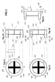
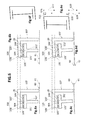
- Figure 1 schematically represents a prior art rotor-stator configuration in the default situation (absence of operational loads) and in the load situation (presence of operational loads), said load situation producing some deformations on the rotor/stator.
- the main goal of this Figure 1 is to provide a good understanding of the problem that is solved using various embodiments of the present invention.
- Figures 1a, 1b, 1c and 1d show an inner structure 101,102,103/101',102',103 and an outer structure 100.
- the most common rotor-stator configurations are those in which the inner structure 101,102,103/101',102',103 is the rotor (i.e. configured to rotate with respect to a rotational axis 110) and the outer structure 100 is the stator (i.e. configured to remain stationary).
- the inner structure 101,102,103/101',102',103 is the stator and the outer structure 100 is the rotor are also possible.
- the inner structure 101,102,103/101',102',103 is always the rotor and the outer structure 100 is always the stator.
- the inner structure 101,102,103/101',102',103 may be the stator and the outer structure 100 may be the rotor.
- Figure 1 a refers to a frontal view, in the direction of the rotational axis 110, of the rotor-stator configuration in the default situation.
- Figure 1b refers to a cross section according to the plane indicated in Figure 1 a through A and A'.
- Figure 1c refers to the view of Figure 1 a but reflecting deformations suffered by the rotor/stator in the load situation.
- Figure 1d refers to the view of Figure 1b but including deformations of the rotor/stator due to operational loads.
- FIG. 1 a shows an air gap 104 between a gap-delimiting region 100 of the stator and a gap-delimiting region 101,102 of the rotor (the concept of gap-delimiting region in the sense of the present invention is explained in later descriptions with reference to Figure 2 ).
- the rotor comprises various spokes 103 each one of which is joined to a zone 102 of the gap-delimiting region 101,102 of the rotor.
- the gap-delimiting region 101,102 of the rotor also comprises zones 101 that are not joined to a spoke 103.
- Zones 102 may suffer different levels of deformation due to operational loads, since spokes 103 substantially retain zones 102 when pulled under the influence of operational loads, whereas zones 101 are not retained by any spoke 103.
- Figure 1a also shows that the air gap 104 is substantially uniform along the entire circumference (i.e. in the 360°). In this sense, Figure 1a reflects that the width 106 of the air gap 104 in zones 102 (joined to a spoke 103) is substantially the same as the width 105 of the air gap 104 in zones 101 (not joined to a spoke 103).
- Figure 1b illustrates another view of the air gap 104 between the gap-delimiting region 100 of the stator and the gap-delimiting region 101',102' of the rotor.
- Figure 1b shows a supporting element 107 which sustains the gap-delimiting region 100 of the stator in such a way that the gap-delimiting region 100 of the stator comprises zones 109 closer to the supporting element 107 and zones 108 more distant from the supporting element 107. Zones 109 are more strongly retained than more distant zones 108, so that deformation on closer zones 109 is smaller than on more distant zones 108.
- Figure 1b also reflects that the air gap 104 is substantially uniform along the entire air gap 104 (in this particular view).
- Figure 1c shows the configuration of the Figure 1 a deformed under the effect of operational loads.
- no deformation of the gap-delimiting region 100 of the rotor is shown, i.e. it is assumed that the circular shape of the gap-delimiting region 100 of 1 a remains unchanged.
- Figure 1c shows that the width 105 of the air gap 104 in zones 101 (not retained by a spoke 103) is significantly reduced with respect to the width 105 shown in 1 a, whereas the width 106 of the air gap 104 in zones 102 (retained by a spoke 103) is also reduced with respect to the width 106 shown in 1a but not so much as the width 105 in zones 101 (not retained by a spoke 103).
- the uniform air gap 104 of 1a is converted into the non-uniform (i.e. degraded) air gap 104 of 1c due to the effect of operational loads.
- Figure 1d shows the configuration of the view 1 b deformed under the effect of operational loads.
- Figure 1d also shows that the width 105' of the air gap 104 in zones 101' (not retained by a spoke 103) is significantly reduced with respect to the width 105' shown in 1 b, whereas the width 106' of the air gap 104 in zones 102' (retained by a spoke 103) is also reduced with respect to the width 106' shown in 1b but not so much as the width 105' in zones 101' (not retained by a spoke 103).
- Figure 1d further shows how the gap-delimiting region 100 is deformed in a way that more distant zones 108 become closer to the gap-delimiting region 101',102' than less distant zones 109, said deformation of the gap-delimiting region 100 also contributing to the degradation of the air gap 104.
- the uniform air gap 104 of 1b is converted into the not uniform (i.e. degraded) air gap 104 of 1d due to the effect of operational loads.
- Said degradation of the air gap 104 may be produced both in the axial direction (as shown in Figure 1d ) and in the radial direction (as shown in Figure 1c ).
- the deformations reflected in Figures 1c and 1d may be due to attractive forces caused by electromagnetic forces between the rotor and the stator, and to the weight of the rotor/stator's structures in which the gap-delimiting regions 100 and 101',102' are comprised. Moreover, the torque of the generator in operation may also contribute to deform the rotor-stator configuration.
- Figure 1e shows an example of forces that could cause the deformations reflected in Figures 1c and 1d , wherein 115 refers to an attractive force acting on the upper (in this particular view) stator structure, 116 refers to the weight of said upper stator structure, and 117 refers to the resulting force from adding said attractive force 115 and said weight 116.
- Figure 1e further shows an attractive force 118 acting on the bottom (in this particular view) stator structure, the weight 119 of said bottom stator structure, and the resulting force 120 from adding the attractive force 118 and the weight 119. Forces deforming the rotor are not shown for reasons of simplicity, but they may be easily devised.
- Figure 1e also shows that both the upper and the bottom stator structure become closer to the rotor, this fact being consequence of that the most influent force in this case is the attractive force 115,118 and not the weight 116,119.
- Figure 1e also shows that the smallest width 121 of the air gap in the upper rotor-stator structure is smaller than the smallest width 122 of the air gap in the bottom rotor-stator structure. This difference is consequence of that the resulting force 117 that makes the stator closer to the rotor in the upper structure has a higher value than the resulting force 120 that makes the stator closer to the rotor in the bottom structure.
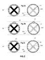
- Figure 2 is a schematic representation of a rotor/stator with permanent magnets illustrating some examples of gap-delimiting regions for a better understanding of later descriptions of embodiments of the invention.
- Figure 2a refers to a view of a typical prior art circular gap-delimiting region 21 in the absence of operational loads
- Figures 2b and 2c refer to respective views of non-circular gap-delimiting regions 24 and 26 also in the absence of operational loads.
- Figures 2a and 2b and 2c refer to respective views of a rotor similar to the rotor shown in Figure 1a , but further comprising permanent magnets 20, plus 22 in 2b and plus 23 in 2c. These three views 2a/2b/2c are shown here to indicate the definition of air gap and gap-delimiting region in the sense of the present invention.
- the rotor comprises some elements (magnets 20/20,22/20,23) that cause a slightly irregular gap-delimiting region (i.e. a non-constant air gap due to e.g. spaces between magnets), but said irregularities may be conceptually smoothed in such a way that a curvilinear gap-delimiting region 21/24/26 may be easily derived.
- all the permanent magnets 20 of 2a substantially have the same size and are uniformly distributed along the 360°, so it may be considered that they constitute a curvilinear gap-delimiting region 21 with circular shape.
- the view 2b is very similar to the view 2a with the only difference of having a single bigger magnet 22 that causes a curvilinear gap-delimiting region 24 with a local protrusion 25 (caused by said bigger magnet 22).
- the view 2c is very similar to the view 2a with the only difference of having a single smaller magnet 23 that causes a curvilinear gap-delimiting region 26 with a local depression 27 (caused by said smaller magnet 23).
- the distorting elements causing slight irregular gap-delimiting regions may also comprise windings (e.g. in self-excited generators) or any other overhanging element comprised in the rotor/stator rim. Therefore, all the previously explained principles, in relation to Figure 2 , for easily inferring curvilinear gap-delimiting regions are of identical consideration with independence from the type of elements causing slight irregularities on the rotor/stator rim.
- Figures 3a and 3b show a prior art rotor-stator configuration
- Figures 3c and 3d show a rotor-stator configuration according to a first embodiment of the invention.
- Figure 3a refers to a section of a rotor-stator configuration very similar to the section 111 of Figure 1 b , with the only difference that the gap-delimiting region 101',102' of the rotor is constituted by permanent magnets 20.
- the most relevant aspect of 3a is that it represents the substantial uniformity of the air gap 104 in the default situation along the entire air gap 104 (in this particular view).
- 3a reflects that the width 106' of the air gap 104 in zones 109 closer to the supporting element 107 and the width 105' of the air gap 104 in zones 108 more distant from the supporting element 107 are substantially the same.
- Figure 3b shows the configuration of Figure 3a deformed under the effect of operational loads.
- the rotor is assumed as not deformed because e.g. the rotor is highly mechanically reinforced and thus very stiff.
- Figure 3b shows how the gap-delimiting region 100 of the stator may be deformed in a way that width 105' of the air gap 104 in more distant zones 108 is significantly reduced in relation to the width 105' of 3a, whereas the width 106' of the air gap 104 in closer zones 109 is also reduced in relation to the width 106' of 3a but not so much as the width 105'.
- the combination of Figures 3a and 3b reflects how operational loads may transform the uniform air gap 104 of 3a into the degraded air gap 104 of 3b.
- Figure 3c shows an amendment of the configuration 3a according to a first embodiment of the invention, said embodiment comprising the presence of one or more metal sheets 30 between some of the magnets 20 and the surface of the rotor on which said magnets 20 are fixed.
- the number and/or width of the inserted metal sheets 30 may depend on the anticipated deformations (shown in Figure 3b ) of the rotor and/or stator in such a way that operational loads will transform the non-uniform air gap 104 of 3c into the uniform air gap 104 of 3d.
- the number and/or width of the inserted metal sheets increases as the proximity of the corresponding magnet 20 to the supporting element 107 of the stator decreases.
- 3c shows that the width 105' of the air gap 104 in more distant zones 108 is not reduced to the same extent (even not at all reduced) as in the closer zones 109, compared with the air gap shown in Figure 3a .
- Figure 3d shows how intentional distortions (protrusions due to the presence of metal sheets 30) on the rotor/stator in the default situation lead to the uniformity of the air gap 104 of 3d in the presence of operational loads.
- the width of the final air gap 104 is substantially the same along the entire air gap 104 (in this particular view) in the presence of operational loads.
- Figure 3d shows that the width 105' of the air gap 104 in more distant zones 108 and the width 106' of the air gap 104 in closer zones 109 are substantially the same when operational loads are present.
- metal sheets 30 may cause a local protrusion on the gap-delimiting region 101',102' of the rotor, that may cause at the same time a non-circular and/or non-constant cross-section of the entire (in the 360°) gap-delimiting region 101',102' of the rotor with respect to the rotational axis.
- local protrusions may be generated by inserting metal sheets between said magnets and their related supporting bases and/or between the supporting bases and the surface of the rotor on which the supporting bases are originally fixed.
- Figure 3e shows an attractive force 315 acting on the upper (in this particular view) stator structure, the weight 316 of said upper stator structure, and the resulting force 317 from adding the attractive force 315 and the weight 316.
- Figure 3e further shows an attractive force 318 acting on the bottom (in this particular view) stator structure, the weight 319 of said bottom stator structure, and the resulting force 320 from adding the attractive force 318 and the weight 319.
- Both the resulting force 317 in the upper structure and the resulting force 320 in the bottom structure makes the gap-delimiting region 100 of the stator closer to the gap-delimiting region 101',102' of the rotor, as illustrated in Figure 3e .
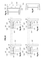
- Figure 4 is a schematic representation of the prior art rotor-stator configuration shown in Figure 3 ( Figures 4a and 4b are identical to Figures 3a and 3b respectively) and a particular rotor-stator configuration according to a second embodiment of the invention.
- Figure 4c shows said particular rotor-stator configuration in accordance with the anticipated deformations (shown in Figure 4b ) of the prior art rotor-stator configuration 4a due to operational loads.
- 4c shows how the stator is intentionally pre-deformed with the objective of obtaining the uniform air gap 104 of 4d when operational loads are present.
- Said pre-deformation of the stator has the goal of moving the gap-delimiting region 100 of the stator away from the gap-delimiting region 101',102' of the rotor, in such a way that the width of the air gap 104 increases as the distance from the supporting element 107 of the stator increases.
- 4c explicitly shows that the width 105' of the air gap 104 in more distant zones 108 is more highly increased with respect to the width 105' of 4a, whereas the width 106' of the air gap 104 in closer zones 109 is more slightly increased with respect to the width 106' of 4a.
- the rotor-stator configuration 4c represents an option for taking advantage of the deformations caused by operational loads, for finally obtaining the uniform air gap 104 of 4d. That is to say, intentional pre-deformation of the stator in the default situation lead to the uniformity of the air gap 104 of 4d in the load situation.
- the width of the final air gap 104 is substantially the same along the entire air gap 104 (in this particular view) when operational loads are present.
- FIG. 4e The deformations due to operational loads reflected in Figures 4b and 4d may be the same as the deformations depicted in Figures 3b and 3d .
- the origin of said deformations is illustrated in Figure 4e (identical to Figure 3e ) and has been explained in reference to Figure 3e .
- Pre-deformation of the stator (as shown in Figures 4c and 4f ) may cause a non-constant and/or non-circular cross-section of the gap-delimiting region 100 of the stator with respect to the rotational axis, which, in this particular case, coincides with the axis of symmetry of the stator because the rotor-stator configuration of Figure 4 is a coaxial configuration.
- An alternative to the pre-deformation of the stator could be to pre-deform the rotor in accordance with the anticipated deformations due to operational loads (shown in Figure 4b ).
- Another alternative could be a combination of both pre-deformation of the stator and pre-deformation of the rotor. Any of said alternatives potentially also allows obtaining a uniform air gap similar to the air gap 104 of Figure 4d .
- Figure 5 is a schematic representation of the prior art rotor-stator configuration shown in Figure 3 ( Figures 5a and 5b are identical to Figures 3a and 3b respectively) and a particular rotor-stator configuration according to a third embodiment of the invention.
- Figure 5c shows said particular rotor-stator configuration in accordance with the anticipated deformations (shown in 5b) of the prior art rotor-stator configuration 5a due to operational loads.
- 5c shows how the surface of the rotor on which the magnets 20 are fixed is selectively machined 50,51 with the objective of obtaining the uniform air gap 104 of 5d when operational loads are present.
- Said selective machining 50,51 of 5c has the goal of moving the gap-delimiting region 101',102' of the rotor away from the gap-delimiting region 100 of the stator, in such a way that the width of the air gap 104 increases as the distance from the supporting element 107 of the stator increases.
- 5c shows that the width 105' of the air gap 104 in more distant zones 108 is highly increased with respect to the width 105' of 5a, whereas the width 106' of the air gap 104 in closer zones 109 is slightly increased (even not increased) with respect to the width 106' of 5a.
- the rotor-stator configuration 5c represents an option for taking advantage of the deformations caused by operational loads for finally obtaining the uniform air gap 104 of 5d in the load situation. That is to say, intentional distortions (consequence of selective machining 50,51) on the rotor/stator in the default situation lead to the uniformity of the air gap 104 of 5d in the presence of operational loads. As shown in 5d, the width of the final air gap 104 is substantially the same along the entire air gap 104 (in this particular view) in the presence of operational loads.
- Selective machining 50,51 of the surface of the rotor on which the magnets 20 are fixed may cause a local depression on the gap-delimiting region 101',102' of the rotor, that may cause at the same time a non-circular and/or non-constant cross-section of the entire (in the 360°) gap-delimiting region 101',102' of the rotor with respect to the rotational axis.
- An alternative to the selective machining 50,51 of the surface of the rotor on which the magnets 20 are fixed could be a selective machining of the magnets 20 in accordance with the anticipated deformations due to operational loads (shown in Figure 5b ).
- another alternative could be a selective machining of the supporting bases.
- Another alternative could be any possible combination of the previously mentioned options: selective machining 50,51 of the surface of the rotor on which the magnets 20 are fixed, selective machining of the magnets, and selective machining of the supporting bases.
- Figure 6 is a schematic representation of the prior art rotor-stator configuration shown in Figure 3 ( Figures 6a and 6b are identical to Figures 3a and 3b respectively) and a particular rotor-stator configuration according to a fourth embodiment of the invention.
- 6a and 6b additionally show the rotational axis 60 of the rotor and the axis of symmetry 61 of the stator, said two axes 60,61 being the same axis because the rotor-stator configuration of 6a and 6b is a coaxial configuration.
- Figure 6c shows the particular rotor-stator configuration in accordance with the anticipated deformations (shown in 6b) of the prior art rotor-stator configuration 6a due to operational loads. Particularly, 6c shows how the rotational axis 60 is inclined with respect to the axis of symmetry 61 of the stator with the objective of obtaining the uniform air gap 104 of 6d when operational loads are present.
- the inclination of the rotational axis 60 with respect to the axis of symmetry 61 of the stator has the goal of moving the gap-delimiting region 101',102' of the rotor away from the gap-delimiting region 100 of the stator, in such a way that the width of the air gap 104 increases as the distance from the supporting element 107 of the stator increases.
- 6c shows that the width 105' of the air gap 104 in more distant zones 108 is highly increased with respect to the width 105' of 6a, whereas the width 106' of the air gap 104 in closer zones 109 is more slightly increased or even reduced with respect to the width 106' of 6a.
- the rotor-stator configuration of 6c represents an option for taking advantage of the deformations caused by operational loads for finally obtaining the uniform air gap 104 of 6d in the load situation. That is to say, intentional distortions (caused by the inclination of the rotational axis 60 with respect to the axis of symmetry 61 of the stator) in the default situation lead to the uniformity of the air gap 104 of 6d in the presence of operational loads. As shown in 6d, the width of the final air gap 104 is substantially the same along the entire air gap 104 (in this particular view) in the presence of operational loads.
- the deformations of the stator due to operational loads reflected in Figures 6b and 6d may be mainly due to the weight of the parts of the stator that comprise the gap-delimiting region 100 of the stator.
- Figure 6e shows an attractive force 615 acting on the upper (in this particular view) stator structure, the weight 616 of said upper stator structure, and the resulting force 617 from adding the attractive force 615 and the weight 616.
- Figure 6e further shows an attractive force 618 acting on the bottom (in this particular view) stator structure, the weight 619 of said bottom stator structure, and the resulting force 620 from adding the attractive force 618 and the weight 619.
- Figure 6e also shows that the upper stator structure become closer to the rotor but the bottom stator structure becomes more distant from the rotor, this fact being consequence of that the most influent forces in this case are the weights 616,619 and not the attractive forces 615,618.
- Figure 6f shows that inclination of the rotational axis 60 with respect to the axis of symmetry 61 of the stator causes a more uniform air gap in both the upper and bottom rotor-stator structures.
- the inclination of the rotational axis 60 with respect to the axis of symmetry 61 of the stator is a way of causing misalignment between said two axis 60,61.
- Another option for obtaining misalignment between the axis 60 and 61 could be displacement of rotational axis 60 of the rotor with respect to the axis of symmetry 61 of the stator.
- Another option could be a combination of both inclination and displacement of one of the axis 60,61 with respect to the other axis 60,61.
- Misalignment of the rotational axis 60 of the rotor with respect to the axis of symmetry 61 of the stator may produce a non-constant cross-section of the gap-delimiting region 101',102' of the rotor and/or a non-coaxial rotor-stator configuration, which may cause a substantially uniform air gap 104 (as shown in Figure 6d ) depending on the anticipated deformations (as shown in Figure 6b ) of the corresponding prior art rotor-stator configuration (as shown in 6a) due to operational loads.
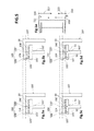
- Figure 7 is a schematic representation of another prior art rotor-stator configuration and a particular rotor-stator configuration according to a fifth embodiment of the invention.
- Figures 7a and 7b refers to a rotor-stator configuration very similar to the configuration of Figures 3a and 3b , with the only difference of that each permanent magnet 20 is fixed to the rotor through a supporting base 70.
- Figure 7c shows the new rotor-stator configuration in accordance with the anticipated deformations (shown in 7b) of the prior art rotor-stator configuration of 7a due to operational loads. Particularly, 7c shows how supporting bases 70 are selectively machined, with the objective of obtaining the uniform air gap 104 of 7d when operational loads are present.
- This selective machining of supporting bases may produce an effect very similar to the effect shown in Figure 5 , which illustrates how intentional distortions based on selectively machining the surface of the rotor on which the magnets are fixed allow obtaining a uniform air gap in the load situation.
- Figure 5 illustrates how intentional distortions based on selectively machining the surface of the rotor on which the magnets are fixed allow obtaining a uniform air gap in the load situation.
- different embodiments of the wind turbine generator of the invention may be obtained by causing the gap-delimiting region of the stator and/or the gap-delimiting region of the rotor to have, in the absence of operational loads, one or more non-circular cross-sections and/or a non-constant cross-section with respect to the rotational axis of the rotor; and/or by causing the rotor and the stator to make up, in the absence of operational loads, a non-coaxial configuration.
- Said non-circular cross-sections and/or non-constant cross-section and/or non-coaxial structure causing the air gap resulting from the presence of operational loads to be more uniform than the air gap in the absence of operational loads.
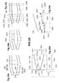
- Figure 8 is a schematic representation of some structural aspects of a first embodiment of the air gap optimizing method.
- This embodiment of the method is based on the use of the Finite Element Method (FEM), whose practical application is often known as Finite Element Analysis (FEA).
- FEM Finite Element Method
- FEA Finite Element Analysis
- This particular example of the air gap optimizing method comprises virtually simulating operation of the rotor and the stator under some operational load, wherein the rotor and the stator are represented in the FEM tool through a virtual rotor and a virtual stator which constitute a virtual air gap between them.
- Figure 8a shows a 3D view of the virtual rotor, whereas the virtual stator (not shown for reasons of simplicity) is assumed to complete a substantially perfect concentric structure with the virtual rotor.
- Figure 8b shows a cross section, according to the rotational axis, of the FEM representation of the virtual rotor in the default situation, i.e. in the absence of operational loads.
- a uniformly distributed load of 23.500 kg/m 2 (even though different amounts could be considered) is emulated in the FEM tool.
- different types of operational loads may be considered, as for example: weight of the rotor and/or the stator; and/or at least one electromagnetic force between the stator and the rotor; and/or torque caused from the rotation of the rotor; etc.
- these different types of loads may be simultaneously simulated, or, in alternative embodiments, each operational load may be independently simulated and the results of said independent simulations may be finally grouped.
- the resulting virtual air gap is compared with a predetermined air gap model. Then, in case of the resulting virtual air gap satisfying the air gap model in terms of having a width between a minimum width and a maximum width along the entire air gap, an ending condition is forced to be satisfied in order to avoid further simulations. Otherwise, in case of the resulting virtual air gap not satisfying the air gap model, some adjustments are calculated and applied to the virtual rotor/stator with the goal of the adjusted virtual rotor/stator to satisfy the air gap model.
- Said calculation and application of adjustments comprise calculating a virtual correction of the virtual rotor and/or the virtual stator for adapting the virtual air gap to satisfy the air gap model, and applying said virtual correction to the virtual rotor and/or virtual stator for its consideration in subsequent virtual simulations.
- Figure 8c shows a cross section, according to the rotational axis, of the FEM representation of the virtual rotor resulting from the one or more executed simulations (until satisfaction of the ending condition).
- the cross section of 8c reflects that zones 101 (not joined to a spoke 103) may be more strongly deformed than zones 102 (joined to a spoke 103), in a manner very similar to the way shown in e.g. Figure 1 c.
- the finally calculated virtual correction (or adjustment) is applied to the rotor and/or the stator.
- Figure 8d illustrates a 3D representation of the corrected virtual rotor, in the absence of operational loads, resulting from the application of the calculated virtual corrections to the virtual rotor once the ending condition has been satisfied.
- Said Figure 8d shows intentional distortions 80 introduced on zones 102 (joined to a spoke 103) for compensating the stronger deformation suffered by zones 101 (not joined to a spoke 103).
- Each of said intentional distortion 80 comprising the aggregation of some metal sheets (two in this particular case) on each zone 102 (joined to a spoke 103).
- Figure 8e shows a cross section, according to the rotational axis, of the FEM representation of the virtual rotor, in the absence of operational loads, resulting from the application of the calculated virtual corrections to the virtual rotor once the ending condition has been satisfied.
- Figure 8e shows aggregation of metal sheets 80 on zones 102 (joined to a spoke 103) but not on zones 101 (not joined to a spoke).
- Figure 8f shows a cross section, according to the rotational axis, of the FEM representation of the virtual rotor, in the presence of operational loads, resulting from the application of the calculated virtual corrections to the virtual rotor once the ending condition has been satisfied.
- Figure 8f shows aggregation of metal sheets 80 on zones 102 (joined to a spoke 103) but not on zones 101 (not joined to a spoke).
- both the Figure 8e and the Figure 8f allows concluding that the applied intentional distortions/protrusions 80 produce a cross section 8f in the load situation that is closer to a circular contour than the cross section 8e in the default situation. That is to say, intentional distortions/protrusions 80 produce an air gap in the load situation that is more uniform than the air gap in the default situation.
- Figure 9 is a schematic representation of some quantitative aspects of the embodiment for which some main structural aspects are shown in Figure 8 .
- Figure 9a refers to a graphic that reflects the distance in the radial direction along the 360° 900 between the intentionally distorted rotor (as shown in Figure 8f ) and the stator in the load situation, and the distance in the radial direction along 360° 901 between the original (not intentionally distorted) rotor (as shown in Figure 8c ) and the stator in the load situation.
- Said graphic 9a clearly reflects that the variation of the air gap width along the 360° is significantly softer in the intentionally distorted rotor 900 configuration with respect to the original (not intentionally distorted) rotor 901 configuration when operational loads are present.
- Figure 9b offers another view of the air gap width along the 360°, wherein 902 refers to the width related to the intentionally distorted rotor 900 configuration and 903 refers to the width related to the not intentionally distorted rotor 901 configuration.
- Figure 9b further offers a graphical view 904 of the intentional distortions/protrusions 80 of Figure 8 along the entire 360°, each of said intentional protrusions 80 corresponding to a peak (or maximum value) in the graphic 904 and to a valley (or minimum value) in the graphic 903.
- Figure 10 is a schematic representation of some discretization aspects of a second embodiment of the air gap optimizing method.
- this figure illustrates how a view of a virtual rotor-stator configuration (and its related virtual air gap 104) may be sectioned for accurately calculating and applying proper virtual corrections to the virtual rotor/stator.
- Figure 10a shows a view of the virtual rotor-stator configuration deformed under the effect of operational loads, said view being very similar to the view 112 of Figure 1d .
- Figure 10b shows a target virtual air gap 1001 in accordance with a predetermined air gap model, and a target gap-delimiting region 1002 of the rotor that permits obtaining said target virtual air gap 1001. For reasons of simplicity, it is assumed in this embodiment that no correction of the gap-delimiting region 100 is applied to the stator.
- Figure 10c shows an example of how the virtual air gap 104 of the view 10a may be divided into a plurality of virtual air gap sections 1003-1006 in a way that each virtual air gap section 1003-1006 is partially delimited by a sub-region of the gap-delimiting region 1000 of the virtual rotor and a sub-region of the gap-delimiting region 100 of the virtual stator.
- Figure 10c also shows the profile 1019 of the gap-delimiting region of the virtual stator in the default situation (i.e. without deformations due to operational loads), and a plurality of reference lines 1031-1033 defining the sections 1003-1006.
- the reference lines 1031-1033 are orthogonal to the profile 1019 of the not deformed gap-delimiting region of the virtual stator in a way that all the sections 1003-1006 have the same width.
- Figure 10d is focused on a single virtual section 1003 for reasons of simplicity, the virtual air gap of said virtual section 1003 being comprised between a virtual sub-region 1034 of the stator and a virtual sub-region 1035 of the rotor.
- Figure 10d illustrates a possible way of calculating a virtual sub-correction 1012 to be applied to the virtual sub-region 1035 of the virtual rotor for obtaining a target virtual sub-region 1036, with the objective of the virtual air gap of the section 1003 to satisfy its related air gap sub-model in accordance with the virtual air gap model 1001.
- the virtual air gap model may comprise a minimum width and a maximum width, so that the virtual air gap satisfies the air gap model when the width of the virtual air gap along the entire virtual air gap is between a minimum width and a maximum width as defined in the air gap model.
- Each virtual air gap sub-model may comprise a minimum width (which e.g. may be equal to the minimum width of its related virtual air gap model plus/minus a certain tolerance), and a maximum width (which e.g.
- the related virtual air gap section may be equal to the maximum width of its related virtual air gap model plus/minus a certain tolerance), so that the related virtual air gap section satisfies the virtual air gap sub-model when the width of the virtual air gap section along the entire virtual air gap section is between the minimum width and the maximum width of the air gap sub-model.
- the reference point 1021 is the intersection point of the reference line 1031 with the target virtual sub-region 1036
- the reference point 1022 is the intersection point of the reference line 1032 with the target virtual sub-region 1036.
- Figure 10e shows a straight line 1029 between the midpoints 1025 and 1026, and a straight line 1030 between the midpoints 1026 and 1027.
- each straight line 1029-1030 may be calculated by applying the same principles and calculations described in the previous paragraph in reference to the virtual section 1003. All the straight lines constitute in conjunction an overall (probably non-straight) line that should have a profile similar to the profile of the target gap-delimiting region 1002 (of Figure 1002).
- the proximity of this overall line to the target gap-delimiting region 1002 will increase as the number of defined section increases and their width decreases. That is to say, the reliability of obtaining the target gap-delimiting region 1002 will be more and more accurate as the number of sections is bigger and the width of said sections is smaller.
- prototype based simulations founded on a rotor/stator prototype and an air gap prototype between them may be applied to obtain the same or similar results.
Abstract
Description
- The present invention relates to a wind turbine generator comprising a rotor, a stator and an air gap between a gap-delimiting region of the stator and a gap-delimiting region of the rotor, said rotor and/or stator being deformable under operational loads.
- The present invention also relates to a method for optimizing an air gap between a gap-delimiting region of a stator and a gap-delimiting region of a rotor of a wind turbine generator, said rotor and/or said stator being deformable under operational loads.
- Wind turbine generators (e.g. self-excited or with permanent magnets) may be exposed to deformations of their rotor and/or stator due to the effect of operational loads (e.g. weight of the rotor/stator, electromagnetic forces between the rotor and stator, etc.). These deformations may cause degradation of the air gap between the rotor and the stator, said degradation producing bad performance and reduction of the life of the generator.
- It is known, for example, that deformations of the rotor/stator and the consequent degradation of the air gap causes unbalanced attracting loads that generate a pull force. This pull force, which increases as air gap degradation increases, may affect the generator's performance, the life of the generator's components such as rotor, stator, generator bearing, elastic coupling and others components of the wind turbine (e.g. frames).
- Nowadays, some designs put into practice generators with heavy parts for increasing the stiffness of the generator's components and, thus, to reduce the deformation of the rotor/stator with the objective of ensuring a constant air gap between the stator and the rotor. However, the application of this approach generates very heavy structures whose e.g. manufacture and transport are very costly.
-
EP2106013A2 shows another approach by disclosing a deflection resistant wind turbine generator in which the stator and the rotor have selectively engageable surfaces that maintain the air gap as substantially stable and permit rotation of the rotor during engagement, said engageable surfaces engaging when the rotor deflects to a predetermined amount of deflection. Moreover,EP2106013A2 also describes that said selectively engageable surfaces may include a set of internal bearings. -
EP2063114A1 shows yet another approach by disclosing a wind turbine that comprises a retaining arrangement (e.g. a main frame in form of a retaining arm) which supports a supporting element of the rotor and is connected to a supporting element of the stator, so that stability of the rotor-stator structure is increased. - Nevertheless, the approaches commented in the two previous paragraphs usually involve complex geometries, introduce additional components, etc. The resulting wind turbine generators may thus be expensive and difficult to maintain.
- There thus still exists a need for new wind turbine generators and air gap optimization methods solving at least some of the above mentioned drawbacks. It is an object of the present invention to fulfil such a need.
- Said object is achieved with a wind turbine generator according to claim 1, and an air gap optimization method according to claim 8.
- In a first aspect, the present invention provides a wind turbine generator comprising a rotor, a stator and an air gap between a gap-delimiting region of the stator and a gap-delimiting region of the rotor; wherein the rotor and/or the stator are deformable under operational loads and configured in such a way that the air gap resulting from the presence of operational loads is more uniform than the air gap in the absence of operational loads.
- The structure of the generator of this first aspect is based on taking advantage of the deformations suffered by the rotor/stator under operational loads by preshaping the rotor/stator in such a way that said deformations cause a more uniform air gap. Two different situations are considered: a default situation, which refers to the absence of operational loads, and a load situation, which refers to the presence of operational loads. The key point of this first aspect of the invention is that the rotor/stator in the default situation has a configuration (e.g. introducing apparent distortions) such that the rotor/stator in the load situation constitutes an air gap more uniform than the air gap in the default situation.
- This innovative first aspect may be seen as a paradox, since an apparently misshapen design of the rotor/stator in the default situation results in a better shape of the rotor/stator in the load situation. Thus, the generator of this first aspect has advantages such as extending the life of the generator, improving its performance, etc. without e.g. increasing the mass/weight of the generator.
- In a second aspect, the present invention provides a method for optimizing an air gap between a gap-delimiting region of a stator and a gap-delimiting region of a rotor of a wind turbine generator, said rotor and/or said stator being deformable under a set of operational loads and said optimization consisting in that the air gap resulting from the presence of the set of operational loads is more uniform than the air gap in the absence of the set of operational loads.
- The method of this second aspect comprises simulating operation of the rotor and the stator under the set of operational loads, said simulation being based on a test rotor representing the rotor, a test stator representing the stator and a test air gap between said test rotor and test stator. Once the simulation is completed, it is verified if the test air gap satisfies an air gap model. In case the test air gap does not satisfy the air gap model, a test correction of the test rotor and/or the test stator for adapting the test air gap to satisfy the air gap model is calculated, and said test correction is applied to the test rotor and/or test stator for its consideration in a next simulation.
- The treatment described in the previous paragraph is repeated until the test air gap satisfies the air gap model. Then, in case of said treatment having produced one or more test corrections, said test corrections are applied to the rotor and/or the stator of the wind turbine generator.
- This method allows producing a generator in which the air gap constituted by the rotor/stator in the load situation is more uniform than the air gap in the default situation. Thus, the principles and advantages commented with respect to the first aspect may also be applied to this second aspect.
- Additional objects, advantages and features of embodiments of the invention will become apparent to those skilled in the art upon examination of the description, or may be learned by practice of the invention.
- Particular embodiments of the present invention will be described in the following by way of non-limiting examples, with reference to the appended drawings, in which:
-
Figure 1 is a schematic representation of a prior art rotor-stator configuration illustrating degradation of the air gap between the rotor and the stator; -
Figure 2 is a schematic representation of a rotor/stator with permanent magnets illustrating some examples of gap-delimiting regions for a better understanding of embodiments of the invention; -
Figure 3 is a schematic representation of a prior art rotor-stator configuration and a rotor-stator configuration according to a first embodiment of the invention; -
Figure 4 is a schematic representation of the prior art rotor-stator configuration shown inFigure 3 and a rotor-stator configuration according to a second embodiment of the invention; -
Figure 5 is a schematic representation of the prior art rotor-stator configuration shown inFigure 3 and a rotor-stator configuration according to a third embodiment of the invention; -
Figure 6 is a schematic representation of the prior art rotor-stator configuration shown inFigure 3 and a rotor-stator configuration according to a fourth embodiment of the invention; -
Figure 7 is a schematic representation of another prior art rotor-stator configuration and a rotor-stator configuration according to a fifth embodiment of the invention; -
Figure 8 is a schematic representation of some structural aspects of a first embodiment of the air gap optimizing method; -
Figure 9 is a schematic representation of some other quantitative aspects of said first embodiment of the air gap optimizing method; and -
Figure 10 is a schematic representation of some discretization aspects of a second embodiment of the air gap optimizing method. - In the following descriptions, numerous specific details are set forth in order to provide a thorough understanding of the present invention. It will be understood by one skilled in the art, however, that the present invention may be practiced without some or all of these specific details. In other instances, well known elements have not been described in detail in order not to unnecessarily obscure the description of the present invention.
-
Figure 1 schematically represents a prior art rotor-stator configuration in the default situation (absence of operational loads) and in the load situation (presence of operational loads), said load situation producing some deformations on the rotor/stator. The main goal of thisFigure 1 is to provide a good understanding of the problem that is solved using various embodiments of the present invention. -
Figures 1a, 1b, 1c and 1d show an inner structure 101,102,103/101',102',103 and anouter structure 100. The most common rotor-stator configurations are those in which the inner structure 101,102,103/101',102',103 is the rotor (i.e. configured to rotate with respect to a rotational axis 110) and theouter structure 100 is the stator (i.e. configured to remain stationary). However, it has to be taken into account that rotor-stator configurations in which the inner structure 101,102,103/101',102',103 is the stator and theouter structure 100 is the rotor are also possible. - For reasons of simplicity, in the following descriptions of embodiments, the inner structure 101,102,103/101',102',103 is always the rotor and the
outer structure 100 is always the stator. However, it should be taken into account that in all embodiments the inner structure 101,102,103/101',102',103 may be the stator and theouter structure 100 may be the rotor. -
Figure 1 a refers to a frontal view, in the direction of therotational axis 110, of the rotor-stator configuration in the default situation.Figure 1b refers to a cross section according to the plane indicated inFigure 1 a through A and A'.Figure 1c refers to the view ofFigure 1 a but reflecting deformations suffered by the rotor/stator in the load situation. AndFigure 1d refers to the view ofFigure 1b but including deformations of the rotor/stator due to operational loads. - The frontal view of
Figure 1 a shows anair gap 104 between a gap-delimitingregion 100 of the stator and a gap-delimiting region 101,102 of the rotor (the concept of gap-delimiting region in the sense of the present invention is explained in later descriptions with reference toFigure 2 ). InFigure 1a , the rotor comprisesvarious spokes 103 each one of which is joined to azone 102 of the gap-delimiting region 101,102 of the rotor. The gap-delimiting region 101,102 of the rotor also compriseszones 101 that are not joined to aspoke 103. Zones 102 (joined to a spoke 103) and zones 101 (not joined to a spoke 103) may suffer different levels of deformation due to operational loads, sincespokes 103 substantially retainzones 102 when pulled under the influence of operational loads, whereaszones 101 are not retained by anyspoke 103.Figure 1a also shows that theair gap 104 is substantially uniform along the entire circumference (i.e. in the 360°). In this sense,Figure 1a reflects that thewidth 106 of theair gap 104 in zones 102 (joined to a spoke 103) is substantially the same as thewidth 105 of theair gap 104 in zones 101 (not joined to a spoke 103). -
Figure 1b illustrates another view of theair gap 104 between the gap-delimitingregion 100 of the stator and the gap-delimiting region 101',102' of the rotor. -
Figure 1b shows a supportingelement 107 which sustains the gap-delimitingregion 100 of the stator in such a way that the gap-delimitingregion 100 of the stator compriseszones 109 closer to the supportingelement 107 andzones 108 more distant from the supportingelement 107.Zones 109 are more strongly retained than moredistant zones 108, so that deformation oncloser zones 109 is smaller than on moredistant zones 108.Figure 1b also reflects that theair gap 104 is substantially uniform along the entire air gap 104 (in this particular view). -
Figure 1c shows the configuration of theFigure 1 a deformed under the effect of operational loads. For reasons of simplicity, no deformation of the gap-delimitingregion 100 of the rotor is shown, i.e. it is assumed that the circular shape of the gap-delimitingregion 100 of 1 a remains unchanged.Figure 1c shows that thewidth 105 of theair gap 104 in zones 101 (not retained by a spoke 103) is significantly reduced with respect to thewidth 105 shown in 1 a, whereas thewidth 106 of theair gap 104 in zones 102 (retained by a spoke 103) is also reduced with respect to thewidth 106 shown in 1a but not so much as thewidth 105 in zones 101 (not retained by a spoke 103). In conclusion, theuniform air gap 104 of 1a is converted into the non-uniform (i.e. degraded)air gap 104 of 1c due to the effect of operational loads. -
Figure 1d shows the configuration of the view 1 b deformed under the effect of operational loads.Figure 1d also shows that thewidth 105' of theair gap 104 in zones 101' (not retained by a spoke 103) is significantly reduced with respect to thewidth 105' shown in 1 b, whereas the width 106' of theair gap 104 in zones 102' (retained by a spoke 103) is also reduced with respect to the width 106' shown in 1b but not so much as thewidth 105' in zones 101' (not retained by a spoke 103).Figure 1d further shows how the gap-delimitingregion 100 is deformed in a way that moredistant zones 108 become closer to the gap-delimiting region 101',102' than lessdistant zones 109, said deformation of the gap-delimitingregion 100 also contributing to the degradation of theair gap 104. Thus, theuniform air gap 104 of 1b is converted into the not uniform (i.e. degraded)air gap 104 of 1d due to the effect of operational loads. Said degradation of theair gap 104 may be produced both in the axial direction (as shown inFigure 1d ) and in the radial direction (as shown inFigure 1c ). - The deformations reflected in
Figures 1c and 1d may be due to attractive forces caused by electromagnetic forces between the rotor and the stator, and to the weight of the rotor/stator's structures in which the gap-delimitingregions 100 and 101',102' are comprised. Moreover, the torque of the generator in operation may also contribute to deform the rotor-stator configuration. - For example,
Figure 1e shows an example of forces that could cause the deformations reflected inFigures 1c and 1d , wherein 115 refers to an attractive force acting on the upper (in this particular view) stator structure, 116 refers to the weight of said upper stator structure, and 117 refers to the resulting force from adding saidattractive force 115 and saidweight 116.Figure 1e further shows anattractive force 118 acting on the bottom (in this particular view) stator structure, theweight 119 of said bottom stator structure, and the resultingforce 120 from adding theattractive force 118 and theweight 119. Forces deforming the rotor are not shown for reasons of simplicity, but they may be easily devised. -
Figure 1e also shows that both the upper and the bottom stator structure become closer to the rotor, this fact being consequence of that the most influent force in this case is the attractive force 115,118 and not the weight 116,119.Figure 1e also shows that thesmallest width 121 of the air gap in the upper rotor-stator structure is smaller than thesmallest width 122 of the air gap in the bottom rotor-stator structure. This difference is consequence of that the resultingforce 117 that makes the stator closer to the rotor in the upper structure has a higher value than the resultingforce 120 that makes the stator closer to the rotor in the bottom structure. -
Figure 2 is a schematic representation of a rotor/stator with permanent magnets illustrating some examples of gap-delimiting regions for a better understanding of later descriptions of embodiments of the invention. In particular,Figure 2a refers to a view of a typical prior art circular gap-delimitingregion 21 in the absence of operational loads, whereasFigures 2b and 2c refer to respective views of non-circular gap-delimitingregions -
Figures 2a and 2b and 2c refer to respective views of a rotor similar to the rotor shown inFigure 1a , but further comprisingpermanent magnets 20, plus 22 in 2b and plus 23 in 2c. These three views 2a/2b/2c are shown here to indicate the definition of air gap and gap-delimiting region in the sense of the present invention. In 2a/2b/2c, the rotor comprises some elements (magnets 20/20,22/20,23) that cause a slightly irregular gap-delimiting region (i.e. a non-constant air gap due to e.g. spaces between magnets), but said irregularities may be conceptually smoothed in such a way that a curvilinear gap-delimitingregion 21/24/26 may be easily derived. - In particular, all the
permanent magnets 20 of 2a substantially have the same size and are uniformly distributed along the 360°, so it may be considered that they constitute a curvilinear gap-delimitingregion 21 with circular shape. The view 2b is very similar to the view 2a with the only difference of having a singlebigger magnet 22 that causes a curvilinear gap-delimitingregion 24 with a local protrusion 25 (caused by said bigger magnet 22). The view 2c is very similar to the view 2a with the only difference of having a singlesmaller magnet 23 that causes a curvilinear gap-delimitingregion 26 with a local depression 27 (caused by said smaller magnet 23). - Still in reference to
Figure 2 , the distorting elements causing slight irregular gap-delimiting regions may also comprise windings (e.g. in self-excited generators) or any other overhanging element comprised in the rotor/stator rim. Therefore, all the previously explained principles, in relation toFigure 2 , for easily inferring curvilinear gap-delimiting regions are of identical consideration with independence from the type of elements causing slight irregularities on the rotor/stator rim. - In relation to
Figure 3, Figures 3a and 3b show a prior art rotor-stator configuration, andFigures 3c and 3d show a rotor-stator configuration according to a first embodiment of the invention.Figure 3a refers to a section of a rotor-stator configuration very similar to thesection 111 ofFigure 1 b , with the only difference that the gap-delimiting region 101',102' of the rotor is constituted bypermanent magnets 20. The most relevant aspect of 3a is that it represents the substantial uniformity of theair gap 104 in the default situation along the entire air gap 104 (in this particular view). In this respect, 3a reflects that the width 106' of theair gap 104 inzones 109 closer to the supportingelement 107 and thewidth 105' of theair gap 104 inzones 108 more distant from the supportingelement 107 are substantially the same. -
Figure 3b shows the configuration ofFigure 3a deformed under the effect of operational loads. For reasons of simplicity, the rotor is assumed as not deformed because e.g. the rotor is highly mechanically reinforced and thus very stiff.Figure 3b shows how the gap-delimitingregion 100 of the stator may be deformed in a way thatwidth 105' of theair gap 104 in moredistant zones 108 is significantly reduced in relation to thewidth 105' of 3a, whereas the width 106' of theair gap 104 incloser zones 109 is also reduced in relation to the width 106' of 3a but not so much as thewidth 105'. Thus, the combination ofFigures 3a and 3b reflects how operational loads may transform theuniform air gap 104 of 3a into thedegraded air gap 104 of 3b. -
Figure 3c shows an amendment of the configuration 3a according to a first embodiment of the invention, said embodiment comprising the presence of one ormore metal sheets 30 between some of themagnets 20 and the surface of the rotor on which saidmagnets 20 are fixed. The number and/or width of the insertedmetal sheets 30 may depend on the anticipated deformations (shown inFigure 3b ) of the rotor and/or stator in such a way that operational loads will transform thenon-uniform air gap 104 of 3c into theuniform air gap 104 of 3d. In this particular example, the number and/or width of the inserted metal sheets increases as the proximity of thecorresponding magnet 20 to the supportingelement 107 of the stator decreases. Particularly, 3c shows that thewidth 105' of theair gap 104 in moredistant zones 108 is not reduced to the same extent (even not at all reduced) as in thecloser zones 109, compared with the air gap shown inFigure 3a . -
Figure 3d shows how intentional distortions (protrusions due to the presence of metal sheets 30) on the rotor/stator in the default situation lead to the uniformity of theair gap 104 of 3d in the presence of operational loads. As shown inFigure 3d , the width of thefinal air gap 104 is substantially the same along the entire air gap 104 (in this particular view) in the presence of operational loads.Figure 3d shows that thewidth 105' of theair gap 104 in moredistant zones 108 and the width 106' of theair gap 104 incloser zones 109 are substantially the same when operational loads are present. - The presence of metal sheets 30 (as shown e.g. in
Figures 3c and 3d ) may cause a local protrusion on the gap-delimiting region 101',102' of the rotor, that may cause at the same time a non-circular and/or non-constant cross-section of the entire (in the 360°) gap-delimiting region 101',102' of the rotor with respect to the rotational axis. In embodiments wherein magnets are fixed on the rotor through supporting bases, local protrusions may be generated by inserting metal sheets between said magnets and their related supporting bases and/or between the supporting bases and the surface of the rotor on which the supporting bases are originally fixed. - The deformations of the stator due to operational loads reflected in
Figures 3b and 3d may be of the same nature than the deformations of the stator shown inFigures 1d and 1e . In this respect,Figure 3e shows anattractive force 315 acting on the upper (in this particular view) stator structure, theweight 316 of said upper stator structure, and the resultingforce 317 from adding theattractive force 315 and theweight 316.Figure 3e further shows anattractive force 318 acting on the bottom (in this particular view) stator structure, theweight 319 of said bottom stator structure, and the resultingforce 320 from adding theattractive force 318 and theweight 319. Both the resultingforce 317 in the upper structure and the resultingforce 320 in the bottom structure makes the gap-delimitingregion 100 of the stator closer to the gap-delimiting region 101',102' of the rotor, as illustrated inFigure 3e . -
Figure 4 is a schematic representation of the prior art rotor-stator configuration shown inFigure 3 (Figures 4a and 4b are identical toFigures 3a and 3b respectively) and a particular rotor-stator configuration according to a second embodiment of the invention.Figure 4c shows said particular rotor-stator configuration in accordance with the anticipated deformations (shown inFigure 4b ) of the prior art rotor-stator configuration 4a due to operational loads. Particularly, 4c shows how the stator is intentionally pre-deformed with the objective of obtaining theuniform air gap 104 of 4d when operational loads are present. - Said pre-deformation of the stator has the goal of moving the gap-delimiting
region 100 of the stator away from the gap-delimiting region 101',102' of the rotor, in such a way that the width of theair gap 104 increases as the distance from the supportingelement 107 of the stator increases. In this respect, 4c explicitly shows that thewidth 105' of theair gap 104 in moredistant zones 108 is more highly increased with respect to thewidth 105' of 4a, whereas the width 106' of theair gap 104 incloser zones 109 is more slightly increased with respect to the width 106' of 4a. - Thus, it may be derived from 4d that the rotor-stator configuration 4c represents an option for taking advantage of the deformations caused by operational loads, for finally obtaining the
uniform air gap 104 of 4d. That is to say, intentional pre-deformation of the stator in the default situation lead to the uniformity of theair gap 104 of 4d in the load situation. As shown inFigure 4d , the width of thefinal air gap 104 is substantially the same along the entire air gap 104 (in this particular view) when operational loads are present. - The deformations due to operational loads reflected in
Figures 4b and 4d may be the same as the deformations depicted inFigures 3b and 3d . The origin of said deformations is illustrated inFigure 4e (identical toFigure 3e ) and has been explained in reference toFigure 3e . Pre-deformation of the stator (as shown inFigures 4c and 4f ) may cause a non-constant and/or non-circular cross-section of the gap-delimitingregion 100 of the stator with respect to the rotational axis, which, in this particular case, coincides with the axis of symmetry of the stator because the rotor-stator configuration ofFigure 4 is a coaxial configuration. - An alternative to the pre-deformation of the stator (as shown in 4c and 4f) could be to pre-deform the rotor in accordance with the anticipated deformations due to operational loads (shown in
Figure 4b ). Another alternative could be a combination of both pre-deformation of the stator and pre-deformation of the rotor. Any of said alternatives potentially also allows obtaining a uniform air gap similar to theair gap 104 ofFigure 4d . -
Figure 5 is a schematic representation of the prior art rotor-stator configuration shown inFigure 3 (Figures 5a and 5b are identical toFigures 3a and 3b respectively) and a particular rotor-stator configuration according to a third embodiment of the invention.Figure 5c shows said particular rotor-stator configuration in accordance with the anticipated deformations (shown in 5b) of the prior art rotor-stator configuration 5a due to operational loads. Particularly, 5c shows how the surface of the rotor on which themagnets 20 are fixed is selectively machined 50,51 with the objective of obtaining theuniform air gap 104 of 5d when operational loads are present. - Said
selective machining region 100 of the stator, in such a way that the width of theair gap 104 increases as the distance from the supportingelement 107 of the stator increases. For example, 5c shows that thewidth 105' of theair gap 104 in moredistant zones 108 is highly increased with respect to thewidth 105' of 5a, whereas the width 106' of theair gap 104 incloser zones 109 is slightly increased (even not increased) with respect to the width 106' of 5a. - As derived from
Figure 5d , the rotor-stator configuration 5c represents an option for taking advantage of the deformations caused by operational loads for finally obtaining theuniform air gap 104 of 5d in the load situation. That is to say, intentional distortions (consequence ofselective machining 50,51) on the rotor/stator in the default situation lead to the uniformity of theair gap 104 of 5d in the presence of operational loads. As shown in 5d, the width of thefinal air gap 104 is substantially the same along the entire air gap 104 (in this particular view) in the presence of operational loads. - The deformations due to operational loads reflected in
Figures 5b and 5d may be the same as the deformations depicted inFigures 3b and 3d . The origin of said deformations is illustrated inFigure 5e (identical toFigure 3e ) and has been explained in reference toFigure 3e . -
Selective machining magnets 20 are fixed (as shown e.g. inFigures 5c and 5d ) may cause a local depression on the gap-delimiting region 101',102' of the rotor, that may cause at the same time a non-circular and/or non-constant cross-section of the entire (in the 360°) gap-delimiting region 101',102' of the rotor with respect to the rotational axis. - An alternative to the
selective machining magnets 20 are fixed (as shown in 5c and 5d), for causing local depressions, could be a selective machining of themagnets 20 in accordance with the anticipated deformations due to operational loads (shown inFigure 5b ). In the case ofmagnets 20 being originally fixed on the rotor through supporting bases, another alternative could be a selective machining of the supporting bases. Another alternative could be any possible combination of the previously mentioned options:selective machining magnets 20 are fixed, selective machining of the magnets, and selective machining of the supporting bases. -
Figure 6 is a schematic representation of the prior art rotor-stator configuration shown inFigure 3 (Figures 6a and 6b are identical toFigures 3a and 3b respectively) and a particular rotor-stator configuration according to a fourth embodiment of the invention. In this case, 6a and 6b additionally show therotational axis 60 of the rotor and the axis ofsymmetry 61 of the stator, said twoaxes Figure 6c shows the particular rotor-stator configuration in accordance with the anticipated deformations (shown in 6b) of the prior art rotor-stator configuration 6a due to operational loads. Particularly, 6c shows how therotational axis 60 is inclined with respect to the axis ofsymmetry 61 of the stator with the objective of obtaining theuniform air gap 104 of 6d when operational loads are present. - The inclination of the
rotational axis 60 with respect to the axis ofsymmetry 61 of the stator has the goal of moving the gap-delimiting region 101',102' of the rotor away from the gap-delimitingregion 100 of the stator, in such a way that the width of theair gap 104 increases as the distance from the supportingelement 107 of the stator increases. For example, 6c shows that thewidth 105' of theair gap 104 in moredistant zones 108 is highly increased with respect to thewidth 105' of 6a, whereas the width 106' of theair gap 104 incloser zones 109 is more slightly increased or even reduced with respect to the width 106' of 6a. - It may be inferred from 6d that the rotor-stator configuration of 6c represents an option for taking advantage of the deformations caused by operational loads for finally obtaining the
uniform air gap 104 of 6d in the load situation. That is to say, intentional distortions (caused by the inclination of therotational axis 60 with respect to the axis ofsymmetry 61 of the stator) in the default situation lead to the uniformity of theair gap 104 of 6d in the presence of operational loads. As shown in 6d, the width of thefinal air gap 104 is substantially the same along the entire air gap 104 (in this particular view) in the presence of operational loads. - The deformations of the stator due to operational loads reflected in
Figures 6b and 6d may be mainly due to the weight of the parts of the stator that comprise the gap-delimitingregion 100 of the stator.Figure 6e shows anattractive force 615 acting on the upper (in this particular view) stator structure, theweight 616 of said upper stator structure, and the resultingforce 617 from adding theattractive force 615 and theweight 616.Figure 6e further shows anattractive force 618 acting on the bottom (in this particular view) stator structure, theweight 619 of said bottom stator structure, and the resultingforce 620 from adding theattractive force 618 and theweight 619. -
Figure 6e also shows that the upper stator structure become closer to the rotor but the bottom stator structure becomes more distant from the rotor, this fact being consequence of that the most influent forces in this case are the weights 616,619 and not the attractive forces 615,618.Figure 6f shows that inclination of therotational axis 60 with respect to the axis ofsymmetry 61 of the stator causes a more uniform air gap in both the upper and bottom rotor-stator structures. - The inclination of the
rotational axis 60 with respect to the axis ofsymmetry 61 of the stator is a way of causing misalignment between said twoaxis axis rotational axis 60 of the rotor with respect to the axis ofsymmetry 61 of the stator. And another option could be a combination of both inclination and displacement of one of theaxis other axis - Misalignment of the
rotational axis 60 of the rotor with respect to the axis ofsymmetry 61 of the stator may produce a non-constant cross-section of the gap-delimiting region 101',102' of the rotor and/or a non-coaxial rotor-stator configuration, which may cause a substantially uniform air gap 104 (as shown inFigure 6d ) depending on the anticipated deformations (as shown inFigure 6b ) of the corresponding prior art rotor-stator configuration (as shown in 6a) due to operational loads. -
Figure 7 is a schematic representation of another prior art rotor-stator configuration and a particular rotor-stator configuration according to a fifth embodiment of the invention.Figures 7a and 7b refers to a rotor-stator configuration very similar to the configuration ofFigures 3a and 3b , with the only difference of that eachpermanent magnet 20 is fixed to the rotor through a supportingbase 70.Figure 7c shows the new rotor-stator configuration in accordance with the anticipated deformations (shown in 7b) of the prior art rotor-stator configuration of 7a due to operational loads. Particularly, 7c shows how supportingbases 70 are selectively machined, with the objective of obtaining theuniform air gap 104 of 7d when operational loads are present. - This selective machining of supporting bases may produce an effect very similar to the effect shown in
Figure 5 , which illustrates how intentional distortions based on selectively machining the surface of the rotor on which the magnets are fixed allow obtaining a uniform air gap in the load situation. Thus, all the principles and advantages previously described in reference toFigure 5 may also be applied to this case. - In summary, different embodiments of the wind turbine generator of the invention may be obtained by causing the gap-delimiting region of the stator and/or the gap-delimiting region of the rotor to have, in the absence of operational loads, one or more non-circular cross-sections and/or a non-constant cross-section with respect to the rotational axis of the rotor; and/or by causing the rotor and the stator to make up, in the absence of operational loads, a non-coaxial configuration. Said non-circular cross-sections and/or non-constant cross-section and/or non-coaxial structure causing the air gap resulting from the presence of operational loads to be more uniform than the air gap in the absence of operational loads.
- With respect to the air gap optimizing method of the invention,
Figure 8 is a schematic representation of some structural aspects of a first embodiment of the air gap optimizing method. This embodiment of the method is based on the use of the Finite Element Method (FEM), whose practical application is often known as Finite Element Analysis (FEA). - This particular example of the air gap optimizing method, based on a FEM software, comprises virtually simulating operation of the rotor and the stator under some operational load, wherein the rotor and the stator are represented in the FEM tool through a virtual rotor and a virtual stator which constitute a virtual air gap between them.
Figure 8a shows a 3D view of the virtual rotor, whereas the virtual stator (not shown for reasons of simplicity) is assumed to complete a substantially perfect concentric structure with the virtual rotor.Figure 8b shows a cross section, according to the rotational axis, of the FEM representation of the virtual rotor in the default situation, i.e. in the absence of operational loads. - In this example of the optimizing method, for reasons of simplicity, only a uniformly distributed load of 23.500 kg/m2 (even though different amounts could be considered) is emulated in the FEM tool. In some embodiments, different types of operational loads may be considered, as for example: weight of the rotor and/or the stator; and/or at least one electromagnetic force between the stator and the rotor; and/or torque caused from the rotation of the rotor; etc. In embodiments of the method, these different types of loads may be simultaneously simulated, or, in alternative embodiments, each operational load may be independently simulated and the results of said independent simulations may be finally grouped.
- Once the simulation has been executed, the resulting virtual air gap is compared with a predetermined air gap model. Then, in case of the resulting virtual air gap satisfying the air gap model in terms of having a width between a minimum width and a maximum width along the entire air gap, an ending condition is forced to be satisfied in order to avoid further simulations. Otherwise, in case of the resulting virtual air gap not satisfying the air gap model, some adjustments are calculated and applied to the virtual rotor/stator with the goal of the adjusted virtual rotor/stator to satisfy the air gap model.
- Said calculation and application of adjustments comprise calculating a virtual correction of the virtual rotor and/or the virtual stator for adapting the virtual air gap to satisfy the air gap model, and applying said virtual correction to the virtual rotor and/or virtual stator for its consideration in subsequent virtual simulations.
-
Figure 8c shows a cross section, according to the rotational axis, of the FEM representation of the virtual rotor resulting from the one or more executed simulations (until satisfaction of the ending condition). The cross section of 8c reflects that zones 101 (not joined to a spoke 103) may be more strongly deformed than zones 102 (joined to a spoke 103), in a manner very similar to the way shown in e.g.Figure 1 c. - Once the loop comprising simulation of operation, and calculation and application of adjustments is ended (by forcing satisfaction of the ending condition), the finally calculated virtual correction (or adjustment) is applied to the rotor and/or the stator.
-
Figure 8d illustrates a 3D representation of the corrected virtual rotor, in the absence of operational loads, resulting from the application of the calculated virtual corrections to the virtual rotor once the ending condition has been satisfied. SaidFigure 8d showsintentional distortions 80 introduced on zones 102 (joined to a spoke 103) for compensating the stronger deformation suffered by zones 101 (not joined to a spoke 103). Each of saidintentional distortion 80 comprising the aggregation of some metal sheets (two in this particular case) on each zone 102 (joined to a spoke 103). -
Figure 8e shows a cross section, according to the rotational axis, of the FEM representation of the virtual rotor, in the absence of operational loads, resulting from the application of the calculated virtual corrections to the virtual rotor once the ending condition has been satisfied. In particular,Figure 8e shows aggregation ofmetal sheets 80 on zones 102 (joined to a spoke 103) but not on zones 101 (not joined to a spoke). -
Figure 8f shows a cross section, according to the rotational axis, of the FEM representation of the virtual rotor, in the presence of operational loads, resulting from the application of the calculated virtual corrections to the virtual rotor once the ending condition has been satisfied. In particular,Figure 8f shows aggregation ofmetal sheets 80 on zones 102 (joined to a spoke 103) but not on zones 101 (not joined to a spoke). - Taking into account both the
Figure 8e and theFigure 8f allows concluding that the applied intentional distortions/protrusions 80 produce a cross section 8f in the load situation that is closer to a circular contour than the cross section 8e in the default situation. That is to say, intentional distortions/protrusions 80 produce an air gap in the load situation that is more uniform than the air gap in the default situation. - Besides, consideration of both
Figure 8c and Figure 8f allows further concluding that the applied intentional distortions/protrusions 80 produce a cross section 8f (in the load situation) that is closer to a circular contour than the cross section 8c (also in the load situation) without such intentional distortions/protrusions 80. In other words, taking into account that the stator completes a concentric structure with the rotor, it may be concluded that intentional distortions/protrusions 80 cause an air gap (in the load situation) that is more uniform than the air gap (also in the load situation) when no intentional distortions/protrusions 80 are present on the rotor. - All the structural principles about intentional misshapenness commented with respect to the figures referring to embodiments of the wind turbine generator of the invention, may also be applied to the embodiments of the method of the invention. For example: non-circular cross-sections may be due to local protrusions/depressions, etc.
-
Figure 9 is a schematic representation of some quantitative aspects of the embodiment for which some main structural aspects are shown inFigure 8 .Figure 9a refers to a graphic that reflects the distance in the radial direction along the 360° 900 between the intentionally distorted rotor (as shown inFigure 8f ) and the stator in the load situation, and the distance in the radial direction along 360° 901 between the original (not intentionally distorted) rotor (as shown inFigure 8c ) and the stator in the load situation. Said graphic 9a clearly reflects that the variation of the air gap width along the 360° is significantly softer in the intentionally distortedrotor 900 configuration with respect to the original (not intentionally distorted) rotor 901 configuration when operational loads are present. -
Figure 9b offers another view of the air gap width along the 360°, wherein 902 refers to the width related to the intentionally distortedrotor 900 configuration and 903 refers to the width related to the not intentionally distorted rotor 901 configuration.Figure 9b further offers agraphical view 904 of the intentional distortions/protrusions 80 ofFigure 8 along the entire 360°, each of saidintentional protrusions 80 corresponding to a peak (or maximum value) in the graphic 904 and to a valley (or minimum value) in the graphic 903. -
Figure 10 is a schematic representation of some discretization aspects of a second embodiment of the air gap optimizing method. In particular, this figure illustrates how a view of a virtual rotor-stator configuration (and its related virtual air gap 104) may be sectioned for accurately calculating and applying proper virtual corrections to the virtual rotor/stator.Figure 10a shows a view of the virtual rotor-stator configuration deformed under the effect of operational loads, said view being very similar to theview 112 ofFigure 1d .Figure 10b shows a targetvirtual air gap 1001 in accordance with a predetermined air gap model, and a target gap-delimitingregion 1002 of the rotor that permits obtaining said targetvirtual air gap 1001. For reasons of simplicity, it is assumed in this embodiment that no correction of the gap-delimitingregion 100 is applied to the stator. -
Figure 10c shows an example of how thevirtual air gap 104 of the view 10a may be divided into a plurality of virtual air gap sections 1003-1006 in a way that each virtual air gap section 1003-1006 is partially delimited by a sub-region of the gap-delimitingregion 1000 of the virtual rotor and a sub-region of the gap-delimitingregion 100 of the virtual stator.Figure 10c also shows theprofile 1019 of the gap-delimiting region of the virtual stator in the default situation (i.e. without deformations due to operational loads), and a plurality of reference lines 1031-1033 defining the sections 1003-1006. In this particular example, the reference lines 1031-1033 are orthogonal to theprofile 1019 of the not deformed gap-delimiting region of the virtual stator in a way that all the sections 1003-1006 have the same width. -
Figure 10d is focused on a singlevirtual section 1003 for reasons of simplicity, the virtual air gap of saidvirtual section 1003 being comprised between avirtual sub-region 1034 of the stator and avirtual sub-region 1035 of the rotor.Figure 10d illustrates a possible way of calculating avirtual sub-correction 1012 to be applied to thevirtual sub-region 1035 of the virtual rotor for obtaining a targetvirtual sub-region 1036, with the objective of the virtual air gap of thesection 1003 to satisfy its related air gap sub-model in accordance with the virtualair gap model 1001. - The virtual air gap model may comprise a minimum width and a maximum width, so that the virtual air gap satisfies the air gap model when the width of the virtual air gap along the entire virtual air gap is between a minimum width and a maximum width as defined in the air gap model. Each virtual air gap sub-model may comprise a minimum width (which e.g. may be equal to the minimum width of its related virtual air gap model plus/minus a certain tolerance), and a maximum width (which e.g. may be equal to the maximum width of its related virtual air gap model plus/minus a certain tolerance), so that the related virtual air gap section satisfies the virtual air gap sub-model when the width of the virtual air gap section along the entire virtual air gap section is between the minimum width and the maximum width of the air gap sub-model.
- In this particular implementation, two
reference points reference point 1021 is the intersection point of thereference line 1031 with the targetvirtual sub-region 1036, whereas thereference point 1022 is the intersection point of thereference line 1032 with the targetvirtual sub-region 1036. - The
distance 1008 between thereference point 1021 and the intersection point of thereference line 1031 with thevirtual sub-region 1034 of the stator may be expressed by the following calculation:
wherein: - 1017 corresponds to the
distance 113 ofFigure 1 , that is to say, the radius of the (circular) gap-delimiting region of the stator in the default situation; - 1018 corresponds to the
distance 114 ofFigure 1 , that is to say, the radius of the (circular) gap-delimiting region of the rotor in the default situation; - 1016 is the deformation of the stator on the reference line 1031 (distance between the intersection point of the
reference line 1031 with thevirtual sub-region 1034 of the stator and the intersection point of thereference line 1031 with theprofile 1019 of the gap-delimiting region of the virtual stator in the default situation); and - 1015 is the deformation of the rotor on the reference line 1031 (distance between the
reference point 1021 and the intersection point of thereference line 1031 with theprofile 1020 of the gap-delimiting region of the virtual rotor in the default situation). - The
distance 1009 between the intersection point of thereference line 1032 with thevirtual sub-region 1034 of the stator and the intersection point of thereference line 1032 with thevirtual sub-region 1035 of the rotor may be expressed by the following calculation:
wherein: - 1014 is the deformation of the stator on the reference line 1032 (distance between the intersection point of the
reference line 1032 with thevirtual sub-region 1034 of the stator and the intersection point of thereference line 1032 with theprofile 1019 of the gap-delimiting region of the virtual stator in the default situation); and - 1013 is the deformation of the rotor on the reference line 1032 (distance between the intersection point of the
reference line 1032 with thevirtual sub-region 1035 of the rotor and the intersection point of thereference line 1032 with theprofile 1020 of the gap-delimiting region of the virtual rotor in the default situation). - The
distance 1010 between the intersection point of thereference line 1032 with thevirtual sub-region 1034 of the stator and thereference point 1022 may be expressed by the following calculation:
wherein: - 1009 = (1017 - 1014) - (1018 + 1013) as explained before; and
- 1012 is the virtual sub-correction to be calculated in relation to the
reference point 1022. - As the
distance 1010 is known from the predetermined air gap model and thedistance 1009 is obtainable from the calculation (1017 - 1014) ― (1018 + 1013), thevirtual sub-correction 1012 related to thereference point 1022 may be obtained from the following calculation:
- Equivalently, the virtual sub-correction related to the
reference point 1021 may be obtained from the following calculation:
- The result of averaging the virtual sub-correction related to the
reference point 1021 and thevirtual sub-correction 1012 related to thereference point 1022 may be assumed as the virtual sub-correction related to thevirtual section 1003. That is to say, the virtual sub-correction related to thevirtual section 1003 may be obtained from the following calculation:
- All the previously described calculations focused to obtain a virtual sub-correction related to a virtual air gap section, may be applied to each of the defined sections 1003-1006, so that a particular virtual sub-correction may be obtained for each of the sections 1003-1006. For example,
Figure 10e shows thevirtual sub-correction 1023 related to thesection 1003, and thevirtual sub-correction 1024 related to thesection 1004. This figure also shows that a midpoint between each pair of sub-corrections related to contiguous sections may be obtained; for example, 1026 is the midpoint between the sub-correction 1023 (of the section 1003) and the sub-correction 1024 (of the section 1004). Once obtained all the midpoints 1025-1027 for all the pairs of continuous sections, a straight line may be assumed between each pair of contiguous midpoints. For example,Figure 10e shows astraight line 1029 between themidpoints straight line 1030 between themidpoints - In the particular case of the
straight line 1029, theinclination 1037 of saidline 1029 may be obtained from the following calculation:
wherein: - 1028 is the half of the
virtual sub-correction 1012 related to the reference point 1022 (1028 = 1012 / 2); and - width_1003 is the width of the
virtual section 1003. - The inclination of each straight line 1029-1030 may be calculated by applying the same principles and calculations described in the previous paragraph in reference to the
virtual section 1003. All the straight lines constitute in conjunction an overall (probably non-straight) line that should have a profile similar to the profile of the target gap-delimiting region 1002 (of Figure 1002). The proximity of this overall line to the target gap-delimitingregion 1002 will increase as the number of defined section increases and their width decreases. That is to say, the reliability of obtaining the target gap-delimitingregion 1002 will be more and more accurate as the number of sections is bigger and the width of said sections is smaller. - All the explained calculations in reference to
Figure 10 may be implemented by using e.g. a FEM tool, as explained in relation toFigures 8 and9 , since this kind of tools are very appropriate to carry out said kind of data processing. - Alternatively to virtual simulations based on a virtual rotor/stator and a virtual air gap between them, prototype based simulations founded on a rotor/stator prototype and an air gap prototype between them may be applied to obtain the same or similar results.
- Although this invention has been disclosed in the context of certain preferred embodiments and examples, it will be understood by those skilled in the art that the present invention extends beyond the specifically disclosed embodiments to other alternative embodiments and/or uses of the invention and obvious modifications and equivalents thereof. Thus, it is intended that the scope of the present invention herein disclosed should not be limited by the particular disclosed embodiments described before, but should be determined only by a fair reading of the claims that follow.
Claims (16)
- Wind turbine generator comprising a rotor, a stator and an air gap between a gap-delimiting region of the stator and a gap-delimiting region of the rotor; wherein the rotor and/or the stator are deformable under operational loads and configured in such a way that the air gap resulting from the presence of operational loads is more uniform than the air gap in the absence of operational loads.
- Wind turbine generator according to claim 1, wherein the gap-delimiting region of the stator and/or the gap-delimiting region of the rotor have, in the absence of operational loads, one or more non-circular cross-sections with respect to the rotational axis of the rotor.
- Wind turbine generator according to claim 2, wherein a non-circular cross-section is due to at least one of the following types of distortion:local protrusion;local depression; andpre-deformation of the rotor/stator.
- Wind turbine generator according to claim 2, wherein a non-circular cross-section is due to at least one local protrusion; and wherein a local protrusion is due to at least one of the following types of arrangements:presence of one or more metal sheets between a magnet fixed on the rotor/stator and the surface of the rotor/stator on which the magnet is fixed;presence of one or more metal sheets between a magnet fixed on the rotor/stator through a supporting base and said supporting base; andpresence of one or more metal sheets between a supporting base through which a magnet is fixed on the rotor/stator and the surface of the rotor/stator on which the magnet is fixed through said supporting base.
- Wind turbine generator according to any of claims 1 to 4, wherein the gap-delimiting region of the stator and/or the gap-delimiting region of the rotor have, in the absence of operational loads, a non-constant cross-section with respect to the rotational axis of the rotor.
- Wind turbine generator according to claim 5, wherein the non-constant cross-section is due to at least one of the following types of distortion:local protrusion;local depression;pre-deformation of the rotor/stator; andinclination of the rotational axis of the rotor with respect to the axis of symmetry of the stator.
- Wind turbine generator according to any of claims 1 to 6, wherein the rotor and the stator make up, in the absence of operational loads, a non-coaxial configuration due to at least one of the following types of distortion:inclination of the rotational axis of the rotor with respect to the axis of symmetry of the stator; anddisplacement of the rotational axis of the rotor with respect to the axis of symmetry of the stator.
- Method for optimizing an air gap between a gap-delimiting region of a stator and a gap-delimiting region of a rotor of a wind turbine generator, said rotor and/or said stator being deformable under a set of operational loads and said optimization consisting in that the air gap resulting from the presence of the set of operational loads is more uniform than the air gap in the absence of the set of operational loads; the method comprising:repeating until an ending condition is satisfied:simulating operation of the rotor and the stator under the set of operational loads, said simulation being based on a test rotor representing the rotor, a test stator representing the stator and a test air gap between said test rotor and test stator;verifying if the test air gap satisfies an air gap model;
in case of positive result:causing satisfaction of the ending condition;in case of negative result:calculating a test correction of the test rotor and/or the test stator for adapting the test air gap to satisfy the air gap model;applying said test correction to the test rotor and/or test stator for its consideration in the next simulation;verifying if one or more test corrections have been produced;
in case of positive result:applying the test corrections to the rotor and/or the stator. - Method according to claim 8, wherein the air gap model comprises a minimum width and a maximum width; and wherein the test air gap satisfies the air gap model when the width of the test air gap along the entire test air gap is between the minimum width and the maximum width.
- Method according to any of claims 8 or 9, wherein the set of operational loads comprises one of the following types of loads:weight of the rotor and/or the stator;at least one electromagnetic force between the stator and the rotor; andtorque caused from the rotation of the rotor.
- Method according to any of claims 8 or 9, wherein the set of operational loads comprises at least two of the following types of loads:weight of the rotor and/or the stator;at least one electromagnetic force between the stator and the rotor; andtorque caused from the rotation of the rotor;and wherein simulating operation of the rotor and the stator under the set of operational loads comprises simultaneously simulating all the operational loads of the set of operational loads.
- Method according to any of claims 8 or 9, wherein the set of operational loads comprises at least two of the following types of loads:weight of the rotor and/or the stator;at least one electromagnetic force between the stator and the rotor; andtorque caused from the rotation of the rotor;and wherein simulating operation of the rotor and the stator under the set of operational loads comprises independently simulating each operational load of the set of operational loads and grouping the results of said independent simulations.
- Method according to any of claims 8 to 12, wherein the simulation is a virtual simulation, the test rotor is a virtual rotor, the test stator is a virtual stator, the test air gap is a virtual air gap, and the test correction is a virtual correction.
- Method according to claim 13, wherein verifying if the virtual air gap satisfies an air gap model comprises:dividing the virtual air gap into a plurality of virtual air gap sections in a way that each virtual air gap section is partially delimited by a sub-region of the virtual rotor and a sub-region of the virtual stator;verifying, for each virtual air gap section, if said virtual air gap section satisfies an air gap sub-model in accordance with the air gap model;wherein calculating a virtual correction of the virtual rotor and/or the virtual stator for adapting the virtual air gap to satisfy the air gap model comprises:for each virtual air gap section not satisfying its related air gap sub-model, calculating a virtual sub-correction of the virtual rotor sub-region and/or the virtual stator sub-region of the virtual air gap section for adapting the virtual air gap section to satisfy its related air gap sub-model;and wherein verifying if one or more virtual corrections have been produced comprises:verifying if one or more virtual sub-corrections have been produced;and wherein applying the virtual corrections to the rotor and/or the stator comprises:applying the virtual sub-corrections to the rotor and/or the stator.
- Method according to claim 14, wherein each air gap sub-model comprises a minimum width and a maximum width; and wherein the virtual air gap section satisfies the air gap sub-model when the width of the virtual air gap section along the entire virtual air gap section is between the minimum width and the maximum width.
- Method according to any of claims 8 to 12, wherein the simulation is a prototype based simulation, the test rotor is a rotor prototype, the test stator is a stator prototype, the test air gap is an air gap prototype, and the test correction is a prototype based correction.
Priority Applications (6)
| Application Number | Priority Date | Filing Date | Title |
|---|---|---|---|
| ES11382246.4T ES2505441T3 (en) | 2011-07-18 | 2011-07-18 | Wind turbine generator |
| EP11382246.4A EP2549100B2 (en) | 2011-07-18 | 2011-07-18 | Wind turbine generator |
| DK11382246.4T DK2549100T3 (en) | 2011-07-18 | 2011-07-18 | Windmill Generator |
| CN201280035422.1A CN103688050B (en) | 2011-07-18 | 2012-07-17 | Wind turbine generator |
| PCT/EP2012/063946 WO2013011004A1 (en) | 2011-07-18 | 2012-07-17 | Wind turbine generator |
| US14/232,244 US9641050B2 (en) | 2011-07-18 | 2012-07-17 | Wind turbine generator |
Applications Claiming Priority (1)
| Application Number | Priority Date | Filing Date | Title |
|---|---|---|---|
| EP11382246.4A EP2549100B2 (en) | 2011-07-18 | 2011-07-18 | Wind turbine generator |
Publications (3)
| Publication Number | Publication Date |
|---|---|
| EP2549100A1 true EP2549100A1 (en) | 2013-01-23 |
| EP2549100B1 EP2549100B1 (en) | 2014-06-18 |
| EP2549100B2 EP2549100B2 (en) | 2021-06-30 |
Family
ID=45747111
Family Applications (1)
| Application Number | Title | Priority Date | Filing Date |
|---|---|---|---|
| EP11382246.4A Active EP2549100B2 (en) | 2011-07-18 | 2011-07-18 | Wind turbine generator |
Country Status (6)
| Country | Link |
|---|---|
| US (1) | US9641050B2 (en) |
| EP (1) | EP2549100B2 (en) |
| CN (1) | CN103688050B (en) |
| DK (1) | DK2549100T3 (en) |
| ES (1) | ES2505441T3 (en) |
| WO (1) | WO2013011004A1 (en) |
Cited By (2)
| Publication number | Priority date | Publication date | Assignee | Title |
|---|---|---|---|---|
| CN110955957A (en) * | 2019-11-08 | 2020-04-03 | 北京万源工业有限公司 | Method and device for determining structural strength of wind turbine hub lifting lug |
| WO2023285192A1 (en) * | 2021-07-13 | 2023-01-19 | Siemens Aktiengesellschaft | Can for an electric rotating machine, production method thereof |
Families Citing this family (6)
| Publication number | Priority date | Publication date | Assignee | Title |
|---|---|---|---|---|
| EP2549100B2 (en) | 2011-07-18 | 2021-06-30 | Ge Renewable Tech Wind Bv | Wind turbine generator |
| EP2806533A1 (en) * | 2013-05-23 | 2014-11-26 | Siemens Aktiengesellschaft | Electrical machine with deformable stator |
| DK3001540T3 (en) * | 2014-09-26 | 2018-06-25 | Alstom Renewable Technologies | Direct drive wind turbines |
| CN107463107B (en) * | 2016-06-06 | 2018-12-25 | 北京金风科创风电设备有限公司 | Generator simulation method and system |
| DE102018201104A1 (en) * | 2018-01-24 | 2019-07-25 | Siemens Gamesa Renewable Energy A/S | Stator for electric machine |
| CN112926129B (en) * | 2021-04-12 | 2022-06-03 | 交通运输部天津水运工程科学研究所 | Optimized design method for wind-resistant ring of steel storage tank applied to port petrochemical steel |
Citations (6)
| Publication number | Priority date | Publication date | Assignee | Title |
|---|---|---|---|---|
| US20060152014A1 (en) * | 2005-01-07 | 2006-07-13 | Grant James J | Method and apparatus for wind turbine air gap control |
| EP2063114A1 (en) | 2007-11-26 | 2009-05-27 | Siemens Aktiengesellschaft | Wind turbine |
| EP2106013A2 (en) | 2008-03-25 | 2009-09-30 | General Electric Company | Wind turbine direct drive airgap control method and system |
| EP2108832A1 (en) * | 2008-04-10 | 2009-10-14 | Siemens Aktiengesellschaft | Generator and wind turbine |
| WO2010072645A1 (en) * | 2008-12-23 | 2010-07-01 | Xemc Darwind Bv | Wind turbine and method for monitoring the gap length between a rotor and a stator of the wind turbine generator |
| EP2237398A1 (en) * | 2009-04-03 | 2010-10-06 | Siemens Aktiengesellschaft | Method and arrangement to adjust an air-gap |
Family Cites Families (12)
| Publication number | Priority date | Publication date | Assignee | Title |
|---|---|---|---|---|
| FR2741486B1 (en) * | 1995-11-20 | 1998-02-20 | Jeumont Ind | METHOD AND DEVICE FOR COMPENSATING FORCE OF MAGNETIC ATTRACTION WITHIN A DISCOID MACHINE |
| DK173641B1 (en) * | 1998-12-15 | 2001-05-14 | Bonus Energy As | Generator, preferably for a wind turbine |
| US6903485B2 (en) | 2003-05-21 | 2005-06-07 | Visteon Global Technologies, Inc. | Claw-pole alternator with non-uniform air gap |
| US7581921B2 (en) * | 2006-06-19 | 2009-09-01 | General Electric Company | Methods and apparatus for controlling rotary machines |
| US7656135B2 (en) * | 2007-01-05 | 2010-02-02 | General Electric Company | Method and apparatus for controlling rotary machines |
| US20080265702A1 (en) * | 2007-04-26 | 2008-10-30 | Don-Lon Yeh | Permanent magnetic brushless motor with length adjustable air gap based on load |
| EP2014917B1 (en) * | 2007-07-10 | 2017-08-30 | Siemens Aktiengesellschaft | Minimising wind turbine generator air gap with a specific shaft bearing arrangement |
| FI20090417A (en) * | 2009-11-10 | 2011-05-11 | Abb Oy | With permanent magnets synchronized synchronous machine and method of manufacture and assembly thereof |
| EP2333933B1 (en) | 2009-12-08 | 2016-03-23 | Siemens Aktiengesellschaft | Arrangement to compensate a non-uniform air gap of an electric machine |
| EP2333934B1 (en) | 2009-12-08 | 2016-07-20 | Siemens Aktiengesellschaft | Arrangement to ensure an air gap in an electric machine |
| EP2369720A1 (en) * | 2010-03-25 | 2011-09-28 | Siemens Aktiengesellschaft | Stator arrangement for an electromechanical transducer, electromechanical transducer and wind turbine |
| EP2549100B2 (en) | 2011-07-18 | 2021-06-30 | Ge Renewable Tech Wind Bv | Wind turbine generator |
-
2011
- 2011-07-18 EP EP11382246.4A patent/EP2549100B2/en active Active
- 2011-07-18 DK DK11382246.4T patent/DK2549100T3/en active
- 2011-07-18 ES ES11382246.4T patent/ES2505441T3/en active Active
-
2012
- 2012-07-17 US US14/232,244 patent/US9641050B2/en active Active
- 2012-07-17 WO PCT/EP2012/063946 patent/WO2013011004A1/en active Application Filing
- 2012-07-17 CN CN201280035422.1A patent/CN103688050B/en active Active
Patent Citations (6)
| Publication number | Priority date | Publication date | Assignee | Title |
|---|---|---|---|---|
| US20060152014A1 (en) * | 2005-01-07 | 2006-07-13 | Grant James J | Method and apparatus for wind turbine air gap control |
| EP2063114A1 (en) | 2007-11-26 | 2009-05-27 | Siemens Aktiengesellschaft | Wind turbine |
| EP2106013A2 (en) | 2008-03-25 | 2009-09-30 | General Electric Company | Wind turbine direct drive airgap control method and system |
| EP2108832A1 (en) * | 2008-04-10 | 2009-10-14 | Siemens Aktiengesellschaft | Generator and wind turbine |
| WO2010072645A1 (en) * | 2008-12-23 | 2010-07-01 | Xemc Darwind Bv | Wind turbine and method for monitoring the gap length between a rotor and a stator of the wind turbine generator |
| EP2237398A1 (en) * | 2009-04-03 | 2010-10-06 | Siemens Aktiengesellschaft | Method and arrangement to adjust an air-gap |
Cited By (2)
| Publication number | Priority date | Publication date | Assignee | Title |
|---|---|---|---|---|
| CN110955957A (en) * | 2019-11-08 | 2020-04-03 | 北京万源工业有限公司 | Method and device for determining structural strength of wind turbine hub lifting lug |
| WO2023285192A1 (en) * | 2021-07-13 | 2023-01-19 | Siemens Aktiengesellschaft | Can for an electric rotating machine, production method thereof |
Also Published As
| Publication number | Publication date |
|---|---|
| CN103688050A (en) | 2014-03-26 |
| EP2549100B2 (en) | 2021-06-30 |
| WO2013011004A1 (en) | 2013-01-24 |
| ES2505441T3 (en) | 2014-10-09 |
| EP2549100B1 (en) | 2014-06-18 |
| US9641050B2 (en) | 2017-05-02 |
| US20140132005A1 (en) | 2014-05-15 |
| CN103688050B (en) | 2016-10-26 |
| DK2549100T3 (en) | 2014-08-11 |
Similar Documents
| Publication | Publication Date | Title |
|---|---|---|
| EP2549100B1 (en) | Wind turbine generator | |
| CN105608300B (en) | The design method of few piece parabolic type variable cross-section main spring end and auxiliary spring gap | |
| US7547186B2 (en) | Nonlinearly stacked low noise turbofan stator | |
| US7029227B2 (en) | Structure comprising a rotor and fixed perturbation sources and method for reducing vibrations in said structure | |
| CN105526290A (en) | Method for designing gaps of end straight sections of diagonal few-leaf main springs and auxiliary springs | |
| Wood | Dual purpose design of small wind turbine blades | |
| KR101933720B1 (en) | Method for controlling output of wind turbine to minimize dynamic load | |
| CN111832185B (en) | Accurate assembly simulation method and system based on skin model | |
| JP2007318880A (en) | Core for field magneton | |
| US6710506B2 (en) | AC generator | |
| US8643208B2 (en) | Method of determining a magnet arrangement | |
| CN110837682A (en) | Industrial robot large arm structure optimization method based on orthogonal test | |
| CN207961235U (en) | A kind of curved spring baffle ring | |
| CN101532540A (en) | Squirrel-cage elastic support and design method thereof | |
| CN111444644A (en) | Industrial robot complete machine rigidity optimization method based on finite element technology | |
| CN110348082A (en) | A kind of design method of toe-in control arm | |
| JPWO2018138994A1 (en) | speaker | |
| CN108317154A (en) | A kind of curved spring baffle ring and its assembly method | |
| JP3682131B2 (en) | Turbine blade and its assembly method | |
| CN109033594A (en) | The analysis method of transmission shaft intermediate support vibratory output when a kind of optimization vehicle starting | |
| EP3159479B1 (en) | A method of assembling a rotor stack | |
| CN106787287B (en) | Motor cogging torque optimization method, motor structure and motor | |
| CN205824018U (en) | A kind of rubber bodies, rubber bushing and automobile | |
| CN112528438B (en) | Dynamic balance optimization design method for spinning head | |
| CN106602808B (en) | Assembly method for reducing cogging torque of permanent magnet motor |
Legal Events
| Date | Code | Title | Description |
|---|---|---|---|
| PUAI | Public reference made under article 153(3) epc to a published international application that has entered the european phase |
Free format text: ORIGINAL CODE: 0009012 |
|
| AK | Designated contracting states |
Kind code of ref document: A1 Designated state(s): AL AT BE BG CH CY CZ DE DK EE ES FI FR GB GR HR HU IE IS IT LI LT LU LV MC MK MT NL NO PL PT RO RS SE SI SK SM TR |
|
| AX | Request for extension of the european patent |
Extension state: BA ME |
|
| 17P | Request for examination filed |
Effective date: 20130723 |
|
| RBV | Designated contracting states (corrected) |
Designated state(s): AL AT BE BG CH CY CZ DE DK EE ES FI FR GB GR HR HU IE IS IT LI LT LU LV MC MK MT NL NO PL PT RO RS SE SI SK SM TR |
|
| GRAP | Despatch of communication of intention to grant a patent |
Free format text: ORIGINAL CODE: EPIDOSNIGR1 |
|
| INTG | Intention to grant announced |
Effective date: 20131205 |
|
| RIN1 | Information on inventor provided before grant (corrected) |
Inventor name: FABREGAT BALBOA, GUILLERMO Inventor name: CLARAMUNT ESTECHA, SANTIAGO Inventor name: GARCIA I ERILL, DANIEL |
|
| GRAS | Grant fee paid |
Free format text: ORIGINAL CODE: EPIDOSNIGR3 |
|
| GRAA | (expected) grant |
Free format text: ORIGINAL CODE: 0009210 |
|
| STAA | Information on the status of an ep patent application or granted ep patent |
Free format text: STATUS: THE PATENT HAS BEEN GRANTED |
|
| RAP1 | Party data changed (applicant data changed or rights of an application transferred) |
Owner name: ALSTOM RENOVABLES ESPANA, S.L. |
|
| AK | Designated contracting states |
Kind code of ref document: B1 Designated state(s): AL AT BE BG CH CY CZ DE DK EE ES FI FR GB GR HR HU IE IS IT LI LT LU LV MC MK MT NL NO PL PT RO RS SE SI SK SM TR |
|
| REG | Reference to a national code |
Ref country code: GB Ref legal event code: FG4D |
|
| REG | Reference to a national code |
Ref country code: CH Ref legal event code: EP |
|
| REG | Reference to a national code |
Ref country code: AT Ref legal event code: REF Ref document number: 673511 Country of ref document: AT Kind code of ref document: T Effective date: 20140715 |
|
| REG | Reference to a national code |
Ref country code: IE Ref legal event code: FG4D |
|
| REG | Reference to a national code |
Ref country code: DE Ref legal event code: R096 Ref document number: 602011007750 Country of ref document: DE Effective date: 20140731 |
|
| REG | Reference to a national code |
Ref country code: DK Ref legal event code: T3 Effective date: 20140805 |
|
| REG | Reference to a national code |
Ref country code: ES Ref legal event code: FG2A Ref document number: 2505441 Country of ref document: ES Kind code of ref document: T3 Effective date: 20141009 |
|
| PG25 | Lapsed in a contracting state [announced via postgrant information from national office to epo] |
Ref country code: GR Free format text: LAPSE BECAUSE OF FAILURE TO SUBMIT A TRANSLATION OF THE DESCRIPTION OR TO PAY THE FEE WITHIN THE PRESCRIBED TIME-LIMIT Effective date: 20140919 Ref country code: NO Free format text: LAPSE BECAUSE OF FAILURE TO SUBMIT A TRANSLATION OF THE DESCRIPTION OR TO PAY THE FEE WITHIN THE PRESCRIBED TIME-LIMIT Effective date: 20140918 Ref country code: CY Free format text: LAPSE BECAUSE OF FAILURE TO SUBMIT A TRANSLATION OF THE DESCRIPTION OR TO PAY THE FEE WITHIN THE PRESCRIBED TIME-LIMIT Effective date: 20140618 Ref country code: LT Free format text: LAPSE BECAUSE OF FAILURE TO SUBMIT A TRANSLATION OF THE DESCRIPTION OR TO PAY THE FEE WITHIN THE PRESCRIBED TIME-LIMIT Effective date: 20140618 Ref country code: FI Free format text: LAPSE BECAUSE OF FAILURE TO SUBMIT A TRANSLATION OF THE DESCRIPTION OR TO PAY THE FEE WITHIN THE PRESCRIBED TIME-LIMIT Effective date: 20140618 |
|
| REG | Reference to a national code |
Ref country code: NL Ref legal event code: VDEP Effective date: 20140618 |
|
| REG | Reference to a national code |
Ref country code: AT Ref legal event code: MK05 Ref document number: 673511 Country of ref document: AT Kind code of ref document: T Effective date: 20140618 |
|
| REG | Reference to a national code |
Ref country code: LT Ref legal event code: MG4D |
|
| PG25 | Lapsed in a contracting state [announced via postgrant information from national office to epo] |
Ref country code: HR Free format text: LAPSE BECAUSE OF FAILURE TO SUBMIT A TRANSLATION OF THE DESCRIPTION OR TO PAY THE FEE WITHIN THE PRESCRIBED TIME-LIMIT Effective date: 20140618 Ref country code: SE Free format text: LAPSE BECAUSE OF FAILURE TO SUBMIT A TRANSLATION OF THE DESCRIPTION OR TO PAY THE FEE WITHIN THE PRESCRIBED TIME-LIMIT Effective date: 20140618 Ref country code: RS Free format text: LAPSE BECAUSE OF FAILURE TO SUBMIT A TRANSLATION OF THE DESCRIPTION OR TO PAY THE FEE WITHIN THE PRESCRIBED TIME-LIMIT Effective date: 20140618 Ref country code: LV Free format text: LAPSE BECAUSE OF FAILURE TO SUBMIT A TRANSLATION OF THE DESCRIPTION OR TO PAY THE FEE WITHIN THE PRESCRIBED TIME-LIMIT Effective date: 20140618 |
|
| PG25 | Lapsed in a contracting state [announced via postgrant information from national office to epo] |
Ref country code: RO Free format text: LAPSE BECAUSE OF FAILURE TO SUBMIT A TRANSLATION OF THE DESCRIPTION OR TO PAY THE FEE WITHIN THE PRESCRIBED TIME-LIMIT Effective date: 20140618 Ref country code: EE Free format text: LAPSE BECAUSE OF FAILURE TO SUBMIT A TRANSLATION OF THE DESCRIPTION OR TO PAY THE FEE WITHIN THE PRESCRIBED TIME-LIMIT Effective date: 20140618 Ref country code: SK Free format text: LAPSE BECAUSE OF FAILURE TO SUBMIT A TRANSLATION OF THE DESCRIPTION OR TO PAY THE FEE WITHIN THE PRESCRIBED TIME-LIMIT Effective date: 20140618 Ref country code: CZ Free format text: LAPSE BECAUSE OF FAILURE TO SUBMIT A TRANSLATION OF THE DESCRIPTION OR TO PAY THE FEE WITHIN THE PRESCRIBED TIME-LIMIT Effective date: 20140618 Ref country code: PT Free format text: LAPSE BECAUSE OF FAILURE TO SUBMIT A TRANSLATION OF THE DESCRIPTION OR TO PAY THE FEE WITHIN THE PRESCRIBED TIME-LIMIT Effective date: 20141020 |
|
| PG25 | Lapsed in a contracting state [announced via postgrant information from national office to epo] |
Ref country code: AT Free format text: LAPSE BECAUSE OF FAILURE TO SUBMIT A TRANSLATION OF THE DESCRIPTION OR TO PAY THE FEE WITHIN THE PRESCRIBED TIME-LIMIT Effective date: 20140618 Ref country code: IS Free format text: LAPSE BECAUSE OF FAILURE TO SUBMIT A TRANSLATION OF THE DESCRIPTION OR TO PAY THE FEE WITHIN THE PRESCRIBED TIME-LIMIT Effective date: 20141018 Ref country code: NL Free format text: LAPSE BECAUSE OF FAILURE TO SUBMIT A TRANSLATION OF THE DESCRIPTION OR TO PAY THE FEE WITHIN THE PRESCRIBED TIME-LIMIT Effective date: 20140618 Ref country code: PL Free format text: LAPSE BECAUSE OF FAILURE TO SUBMIT A TRANSLATION OF THE DESCRIPTION OR TO PAY THE FEE WITHIN THE PRESCRIBED TIME-LIMIT Effective date: 20140618 |
|
| REG | Reference to a national code |
Ref country code: CH Ref legal event code: PL |
|
| REG | Reference to a national code |
Ref country code: DE Ref legal event code: R026 Ref document number: 602011007750 Country of ref document: DE |
|
| PLBI | Opposition filed |
Free format text: ORIGINAL CODE: 0009260 |
|
| PG25 | Lapsed in a contracting state [announced via postgrant information from national office to epo] |
Ref country code: MC Free format text: LAPSE BECAUSE OF FAILURE TO SUBMIT A TRANSLATION OF THE DESCRIPTION OR TO PAY THE FEE WITHIN THE PRESCRIBED TIME-LIMIT Effective date: 20140618 |
|
| 26 | Opposition filed |
Opponent name: SIEMENS AKTIENGESELLSCHAFT Effective date: 20150316 |
|
| REG | Reference to a national code |
Ref country code: IE Ref legal event code: MM4A |
|
| PLAX | Notice of opposition and request to file observation + time limit sent |
Free format text: ORIGINAL CODE: EPIDOSNOBS2 |
|
| PG25 | Lapsed in a contracting state [announced via postgrant information from national office to epo] |
Ref country code: CH Free format text: LAPSE BECAUSE OF NON-PAYMENT OF DUE FEES Effective date: 20140731 Ref country code: LI Free format text: LAPSE BECAUSE OF NON-PAYMENT OF DUE FEES Effective date: 20140731 Ref country code: IT Free format text: LAPSE BECAUSE OF FAILURE TO SUBMIT A TRANSLATION OF THE DESCRIPTION OR TO PAY THE FEE WITHIN THE PRESCRIBED TIME-LIMIT Effective date: 20140618 |
|
| REG | Reference to a national code |
Ref country code: DE Ref legal event code: R026 Ref document number: 602011007750 Country of ref document: DE Effective date: 20150316 |
|
| PG25 | Lapsed in a contracting state [announced via postgrant information from national office to epo] |
Ref country code: BE Free format text: LAPSE BECAUSE OF FAILURE TO SUBMIT A TRANSLATION OF THE DESCRIPTION OR TO PAY THE FEE WITHIN THE PRESCRIBED TIME-LIMIT Effective date: 20140618 |
|
| PG25 | Lapsed in a contracting state [announced via postgrant information from national office to epo] |
Ref country code: SI Free format text: LAPSE BECAUSE OF FAILURE TO SUBMIT A TRANSLATION OF THE DESCRIPTION OR TO PAY THE FEE WITHIN THE PRESCRIBED TIME-LIMIT Effective date: 20140618 |
|
| PLBB | Reply of patent proprietor to notice(s) of opposition received |
Free format text: ORIGINAL CODE: EPIDOSNOBS3 |
|
| PG25 | Lapsed in a contracting state [announced via postgrant information from national office to epo] |
Ref country code: IE Free format text: LAPSE BECAUSE OF NON-PAYMENT OF DUE FEES Effective date: 20140718 |
|
| PG25 | Lapsed in a contracting state [announced via postgrant information from national office to epo] |
Ref country code: SM Free format text: LAPSE BECAUSE OF FAILURE TO SUBMIT A TRANSLATION OF THE DESCRIPTION OR TO PAY THE FEE WITHIN THE PRESCRIBED TIME-LIMIT Effective date: 20140618 |
|
| PG25 | Lapsed in a contracting state [announced via postgrant information from national office to epo] |
Ref country code: BG Free format text: LAPSE BECAUSE OF FAILURE TO SUBMIT A TRANSLATION OF THE DESCRIPTION OR TO PAY THE FEE WITHIN THE PRESCRIBED TIME-LIMIT Effective date: 20140618 Ref country code: MT Free format text: LAPSE BECAUSE OF FAILURE TO SUBMIT A TRANSLATION OF THE DESCRIPTION OR TO PAY THE FEE WITHIN THE PRESCRIBED TIME-LIMIT Effective date: 20140618 |
|
| REG | Reference to a national code |
Ref country code: FR Ref legal event code: PLFP Year of fee payment: 6 |
|
| PG25 | Lapsed in a contracting state [announced via postgrant information from national office to epo] |
Ref country code: TR Free format text: LAPSE BECAUSE OF FAILURE TO SUBMIT A TRANSLATION OF THE DESCRIPTION OR TO PAY THE FEE WITHIN THE PRESCRIBED TIME-LIMIT Effective date: 20140618 Ref country code: HU Free format text: LAPSE BECAUSE OF FAILURE TO SUBMIT A TRANSLATION OF THE DESCRIPTION OR TO PAY THE FEE WITHIN THE PRESCRIBED TIME-LIMIT; INVALID AB INITIO Effective date: 20110718 Ref country code: LU Free format text: LAPSE BECAUSE OF NON-PAYMENT OF DUE FEES Effective date: 20140718 |
|
| RIC2 | Information provided on ipc code assigned after grant |
Ipc: F03D 9/00 20160101AFI20170127BHEP Ipc: H02K 1/06 20060101ALI20170127BHEP Ipc: F03D 7/02 20060101ALI20170127BHEP Ipc: F03D 17/00 20160101ALI20170127BHEP Ipc: H02K 7/18 20060101ALI20170127BHEP Ipc: H02K 15/16 20060101ALI20170127BHEP |
|
| APBM | Appeal reference recorded |
Free format text: ORIGINAL CODE: EPIDOSNREFNO |
|
| APBP | Date of receipt of notice of appeal recorded |
Free format text: ORIGINAL CODE: EPIDOSNNOA2O |
|
| APAH | Appeal reference modified |
Free format text: ORIGINAL CODE: EPIDOSCREFNO |
|
| APBM | Appeal reference recorded |
Free format text: ORIGINAL CODE: EPIDOSNREFNO |
|
| APBP | Date of receipt of notice of appeal recorded |
Free format text: ORIGINAL CODE: EPIDOSNNOA2O |
|
| RAP2 | Party data changed (patent owner data changed or rights of a patent transferred) |
Owner name: GENERAL ELECTRIC RENOVABLES ESPANA S.L. |
|
| APBQ | Date of receipt of statement of grounds of appeal recorded |
Free format text: ORIGINAL CODE: EPIDOSNNOA3O |
|
| APBQ | Date of receipt of statement of grounds of appeal recorded |
Free format text: ORIGINAL CODE: EPIDOSNNOA3O |
|
| REG | Reference to a national code |
Ref country code: FR Ref legal event code: PLFP Year of fee payment: 7 |
|
| PLAB | Opposition data, opponent's data or that of the opponent's representative modified |
Free format text: ORIGINAL CODE: 0009299OPPO |
|
| R26 | Opposition filed (corrected) |
Opponent name: SIEMENS AKTIENGESELLSCHAFT Effective date: 20150316 |
|
| REG | Reference to a national code |
Ref country code: DE Ref legal event code: R081 Ref document number: 602011007750 Country of ref document: DE Owner name: GE RENEWABLE TECHNOLOGIES WIND B.V., NL Free format text: FORMER OWNER: ALSTOM RENOVABLES ESPANA, S.L., BARCELONA, ES |
|
| REG | Reference to a national code |
Ref country code: ES Ref legal event code: PC2A Owner name: GE RENEWABLE TECHNOLOGIES WIND B.V. Effective date: 20180123 |
|
| REG | Reference to a national code |
Ref country code: FR Ref legal event code: PLFP Year of fee payment: 8 |
|
| PG25 | Lapsed in a contracting state [announced via postgrant information from national office to epo] |
Ref country code: MK Free format text: LAPSE BECAUSE OF FAILURE TO SUBMIT A TRANSLATION OF THE DESCRIPTION OR TO PAY THE FEE WITHIN THE PRESCRIBED TIME-LIMIT Effective date: 20140618 |
|
| RAP2 | Party data changed (patent owner data changed or rights of a patent transferred) |
Owner name: GE RENEWABLE TECHNOLOGIES WIND B.V. |
|
| PG25 | Lapsed in a contracting state [announced via postgrant information from national office to epo] |
Ref country code: AL Free format text: LAPSE BECAUSE OF FAILURE TO SUBMIT A TRANSLATION OF THE DESCRIPTION OR TO PAY THE FEE WITHIN THE PRESCRIBED TIME-LIMIT Effective date: 20140618 |
|
| REG | Reference to a national code |
Ref country code: GB Ref legal event code: 732E Free format text: REGISTERED BETWEEN 20190117 AND 20190123 |
|
| RIC2 | Information provided on ipc code assigned after grant |
Ipc: F03D 17/00 20160101ALI20170127BHEP Ipc: F03D 7/02 20060101ALI20170127BHEP Ipc: H02K 15/16 20060101ALI20170127BHEP Ipc: H02K 7/18 20060101ALI20170127BHEP Ipc: F03D 9/00 20160101AFI20170127BHEP Ipc: H02K 1/06 20060101ALI20170127BHEP |
|
| REG | Reference to a national code |
Ref country code: GB Ref legal event code: 732E Free format text: REGISTERED BETWEEN 20190124 AND 20190130 |
|
| APAH | Appeal reference modified |
Free format text: ORIGINAL CODE: EPIDOSCREFNO |
|
| PGFP | Annual fee paid to national office [announced via postgrant information from national office to epo] |
Ref country code: ES Payment date: 20190801 Year of fee payment: 9 |
|
| REG | Reference to a national code |
Ref country code: DE Ref legal event code: R100 Ref document number: 602011007750 Country of ref document: DE |
|
| APBU | Appeal procedure closed |
Free format text: ORIGINAL CODE: EPIDOSNNOA9O |
|
| PLCK | Communication despatched that opposition was rejected |
Free format text: ORIGINAL CODE: EPIDOSNREJ1 |
|
| STAA | Information on the status of an ep patent application or granted ep patent |
Free format text: STATUS: OPPOSITION REJECTED |
|
| PLBN | Opposition rejected |
Free format text: ORIGINAL CODE: 0009273 |
|
| PUAH | Patent maintained in amended form |
Free format text: ORIGINAL CODE: 0009272 |
|
| STAA | Information on the status of an ep patent application or granted ep patent |
Free format text: STATUS: OPPOSITION REJECTED Free format text: STATUS: PATENT MAINTAINED AS AMENDED |
|
| PUAD | Information related to the publication of a b2 document modified or deleted |
Free format text: ORIGINAL CODE: 0009399EPPU |
|
| 27A | Patent maintained in amended form |
Effective date: 20210630 |
|
| 27O | Opposition rejected |
Effective date: 20210414 |
|
| AK | Designated contracting states |
Kind code of ref document: B2 Designated state(s): AL AT BE BG CH CY CZ DE DK EE ES FI FR GB GR HR HU IE IS IT LI LT LU LV MC MK MT NL NO PL PT RO RS SE SI SK SM TR |
|
| REG | Reference to a national code |
Ref country code: DE Ref legal event code: R102 Ref document number: 602011007750 Country of ref document: DE |
|
| D27A | Patent maintained in amended form (deleted) | ||
| DB2 | B2 document published (deleted) | ||
| PGFP | Annual fee paid to national office [announced via postgrant information from national office to epo] |
Ref country code: DK Payment date: 20210624 Year of fee payment: 11 |
|
| PG25 | Lapsed in a contracting state [announced via postgrant information from national office to epo] |
Ref country code: ES Free format text: LAPSE BECAUSE OF FAILURE TO SUBMIT A TRANSLATION OF THE DESCRIPTION OR TO PAY THE FEE WITHIN THE PRESCRIBED TIME-LIMIT Effective date: 20210630 |
|
| PG25 | Lapsed in a contracting state [announced via postgrant information from national office to epo] |
Ref country code: DK Free format text: LAPSE BECAUSE OF FAILURE TO SUBMIT A TRANSLATION OF THE DESCRIPTION OR TO PAY THE FEE WITHIN THE PRESCRIBED TIME-LIMIT Effective date: 20210708 |
|
| P01 | Opt-out of the competence of the unified patent court (upc) registered |
Effective date: 20230529 |
|
| PGFP | Annual fee paid to national office [announced via postgrant information from national office to epo] |
Ref country code: FR Payment date: 20230621 Year of fee payment: 13 |
|
| PGFP | Annual fee paid to national office [announced via postgrant information from national office to epo] |
Ref country code: GB Payment date: 20230620 Year of fee payment: 13 |
|
| PGFP | Annual fee paid to national office [announced via postgrant information from national office to epo] |
Ref country code: DE Payment date: 20230620 Year of fee payment: 13 |