EP2548943A1 - Clamping insert for cell culture - Google Patents
Clamping insert for cell culture Download PDFInfo
- Publication number
- EP2548943A1 EP2548943A1 EP20110174937 EP11174937A EP2548943A1 EP 2548943 A1 EP2548943 A1 EP 2548943A1 EP 20110174937 EP20110174937 EP 20110174937 EP 11174937 A EP11174937 A EP 11174937A EP 2548943 A1 EP2548943 A1 EP 2548943A1
- Authority
- EP
- European Patent Office
- Prior art keywords
- inner holder
- porous substrate
- lower support
- clamping insert
- insert
- Prior art date
- Legal status (The legal status is an assumption and is not a legal conclusion. Google has not performed a legal analysis and makes no representation as to the accuracy of the status listed.)
- Granted
Links
Images


Classifications
-
- C—CHEMISTRY; METALLURGY
- C12—BIOCHEMISTRY; BEER; SPIRITS; WINE; VINEGAR; MICROBIOLOGY; ENZYMOLOGY; MUTATION OR GENETIC ENGINEERING
- C12M—APPARATUS FOR ENZYMOLOGY OR MICROBIOLOGY; APPARATUS FOR CULTURING MICROORGANISMS FOR PRODUCING BIOMASS, FOR GROWING CELLS OR FOR OBTAINING FERMENTATION OR METABOLIC PRODUCTS, i.e. BIOREACTORS OR FERMENTERS
- C12M25/00—Means for supporting, enclosing or fixing the microorganisms, e.g. immunocoatings
- C12M25/02—Membranes; Filters
- C12M25/04—Membranes; Filters in combination with well or multiwell plates, i.e. culture inserts
-
- C—CHEMISTRY; METALLURGY
- C12—BIOCHEMISTRY; BEER; SPIRITS; WINE; VINEGAR; MICROBIOLOGY; ENZYMOLOGY; MUTATION OR GENETIC ENGINEERING
- C12M—APPARATUS FOR ENZYMOLOGY OR MICROBIOLOGY; APPARATUS FOR CULTURING MICROORGANISMS FOR PRODUCING BIOMASS, FOR GROWING CELLS OR FOR OBTAINING FERMENTATION OR METABOLIC PRODUCTS, i.e. BIOREACTORS OR FERMENTERS
- C12M23/00—Constructional details, e.g. recesses, hinges
-
- C—CHEMISTRY; METALLURGY
- C12—BIOCHEMISTRY; BEER; SPIRITS; WINE; VINEGAR; MICROBIOLOGY; ENZYMOLOGY; MUTATION OR GENETIC ENGINEERING
- C12M—APPARATUS FOR ENZYMOLOGY OR MICROBIOLOGY; APPARATUS FOR CULTURING MICROORGANISMS FOR PRODUCING BIOMASS, FOR GROWING CELLS OR FOR OBTAINING FERMENTATION OR METABOLIC PRODUCTS, i.e. BIOREACTORS OR FERMENTERS
- C12M23/00—Constructional details, e.g. recesses, hinges
- C12M23/48—Holding appliances; Racks; Supports
-
- C—CHEMISTRY; METALLURGY
- C12—BIOCHEMISTRY; BEER; SPIRITS; WINE; VINEGAR; MICROBIOLOGY; ENZYMOLOGY; MUTATION OR GENETIC ENGINEERING
- C12M—APPARATUS FOR ENZYMOLOGY OR MICROBIOLOGY; APPARATUS FOR CULTURING MICROORGANISMS FOR PRODUCING BIOMASS, FOR GROWING CELLS OR FOR OBTAINING FERMENTATION OR METABOLIC PRODUCTS, i.e. BIOREACTORS OR FERMENTERS
- C12M25/00—Means for supporting, enclosing or fixing the microorganisms, e.g. immunocoatings
- C12M25/06—Plates; Walls; Drawers; Multilayer plates
- C12M25/08—Plates; Walls; Drawers; Multilayer plates electrically charged
-
- C—CHEMISTRY; METALLURGY
- C12—BIOCHEMISTRY; BEER; SPIRITS; WINE; VINEGAR; MICROBIOLOGY; ENZYMOLOGY; MUTATION OR GENETIC ENGINEERING
- C12M—APPARATUS FOR ENZYMOLOGY OR MICROBIOLOGY; APPARATUS FOR CULTURING MICROORGANISMS FOR PRODUCING BIOMASS, FOR GROWING CELLS OR FOR OBTAINING FERMENTATION OR METABOLIC PRODUCTS, i.e. BIOREACTORS OR FERMENTERS
- C12M35/00—Means for application of stress for stimulating the growth of microorganisms or the generation of fermentation or metabolic products; Means for electroporation or cell fusion
- C12M35/02—Electrical or electromagnetic means, e.g. for electroporation or for cell fusion
-
- C—CHEMISTRY; METALLURGY
- C12—BIOCHEMISTRY; BEER; SPIRITS; WINE; VINEGAR; MICROBIOLOGY; ENZYMOLOGY; MUTATION OR GENETIC ENGINEERING
- C12M—APPARATUS FOR ENZYMOLOGY OR MICROBIOLOGY; APPARATUS FOR CULTURING MICROORGANISMS FOR PRODUCING BIOMASS, FOR GROWING CELLS OR FOR OBTAINING FERMENTATION OR METABOLIC PRODUCTS, i.e. BIOREACTORS OR FERMENTERS
- C12M41/00—Means for regulation, monitoring, measurement or control, e.g. flow regulation
- C12M41/46—Means for regulation, monitoring, measurement or control, e.g. flow regulation of cellular or enzymatic activity or functionality, e.g. cell viability
-
- Y—GENERAL TAGGING OF NEW TECHNOLOGICAL DEVELOPMENTS; GENERAL TAGGING OF CROSS-SECTIONAL TECHNOLOGIES SPANNING OVER SEVERAL SECTIONS OF THE IPC; TECHNICAL SUBJECTS COVERED BY FORMER USPC CROSS-REFERENCE ART COLLECTIONS [XRACs] AND DIGESTS
- Y10—TECHNICAL SUBJECTS COVERED BY FORMER USPC
- Y10T—TECHNICAL SUBJECTS COVERED BY FORMER US CLASSIFICATION
- Y10T29/00—Metal working
- Y10T29/49—Method of mechanical manufacture
- Y10T29/49998—Work holding
Definitions
- the present invention relates to the field of cell biology and cell culture. It more particularly relates to inserts used together with microwell plates to perform various biological experiments.
- In vitro models of biological barriers are used, for example, to screen potential pharmaceuticals and toxins for their ability to enter into and to move around the human body.
- In vitro models consist of a single layer or multiple layers of cells that are cultured in the laboratory so as to mimic the properties of biological barriers in the body.
- the function of biological barriers in the body is to divide the inside of the body from the outside (e.g skin, lungs, the intestines) or different compartments of the body from each other (e.g. the blood-brain barrier, the walls of blood vessels).
- the blood-brain barrier e.g. the blood-brain barrier, the walls of blood vessels.
- in vitro models of biological barriers are cultured on porous membranes. This is commonly done using microporous well inserts.
- the well insert is used in combination with a microwell plate consisting of a number of wells made in plastic.
- the insert is inserted into a well, which it divides in two, a top (apical) compartment and a bottom (basolateral) compartment which communicate via a porous membrane at the bottom of the insert.
- Cells are added to the apical side of the well insert and are cultured on the porous membrane. Typically, the cells will grow to form a watertight layer that divides the apical from the basolateral compartment, as in the body.
- the porous membrane is usually made of polymers or of inorganic aluminium oxide. It is welded, moulded or glued to the wall of the insert, so as to obtain a perfect seal. Indeed, it is necessary that the exchanges of material between apical and basolateral compartments take place only through the microporous membrane and the cell layer upon it.
- the membrane and the insert form a disposable assembly.
- candidate drugs are added to the apical compartment, which represents the outside of the body for a skin model, or the inside of the lungs, or of the intestines, etc.... Permeation is quantified by measuring the concentration of the candidate drug in the basolateral compartment, which represents the inside of the body, after a fixed time.
- porous substrates are fabricated by first depositing a thin layer of ceramic material, such as Si 3 N 4 , on a silicon wafer. Pores are then etched in the Si 3 N 4 by photolithography followed by a dry etch. The silicon wafer is then etched from the other side to remove the entire thickness of silicon in selected areas, leaving a set of supports for the transparent porous substrate that remain after removal of the silicon.
- the resulting porous substrate comprises a silicon nitride membrane supported on a silicon frame which gives it suitable mechanical properties.
- this kind of substrate presents two major drawbacks. Firstly, it is more expensive than the commonly used polymer microporous substrates. This can be overcome by its reuse. In addition, it requires a specific holder that makes it compatible with a commercial well plate and also with routine laboratory practice.
- the present invention aims to alleviate these problems and allow a practical use of this type of substrate.
- the invention concerns a clamping insert for cell culture comprising:
- the invention also concerns an assembly comprising such a clamping insert and a porous substrate.
- the invention also concerns a method for clamping a porous substrate with such an insert. Said method comprises the following steps:
- a dedicated tool comprising some driving structures intended to cooperate with corresponding structures arranged in the inner holder may be used for the tightening step if appropriate.
- Figures 1 a and 1 b are two perspective views of an embodiment of the lower support, figure 1c represents an anti-wear ring intended to cooperate with the lower support.
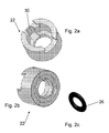
- Figures 2a and 2b are two perspective views of an embodiment of the inner holder, figure 2c represents a seal intended to cooperate with the inner holder.
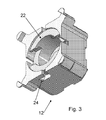
- Figure 3 show the assembled clamping insert according one embodiment of the invention.
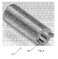
- Figure 4 represents an example of an assembling/disassembling tool adapted to the invention.
- Figure 5 and 6 propose sketches of two other embodiments of the invention.
- FIGs 1 , 2 and 3 represent a preferred embodiment of an insert according to the invention.
- This insert aims to facilitate the use as a biological substrate of a porous substrate made with a Si 3 N 4 layer deposited on a silicon wafer and then micromachined.
- a porous substrate 10 can be seen on figures 5 and 6 .
- This substrate as such is not part of the invention and will not be described in detail.
- the insert according to the invention comprises a lower support 12 ( figures 1a and 1b ) comprising a hollow member 14 sized to be engaged in a well of a microplate, preferably of a standard microplate.
- the hollow member 14 could be made in different suitable materials, like plastic or aluminium.
- PEEK polyether ether ketone
- PC polycarbonate
- polystyrene or similar polymers are well suited since they resist typical sterilization conditions and they can be injection moulded in a low-cost production process.
- the hollow member 14 is open at both its ends. At one end, its wall defines a reverse side which forms a support surface 16 for the porous substrate 10.
- the lower support 12 furthermore comprises some flanges 18 extending from the wall of the hollow member 14 oppositely to the end comprising said support surface 16. These flanges 18 define retaining means. They are sized and arranged so as to allow the lower support 12 and the whole insert to rest on the sides of the microplate well and so as to avoid the whole assembly touching the bottom of the microplate well.
- the lower support 12 furthermore comprises first tightening means.
- these first tightening means take shape of two grooves 20, diametrically opposed.
- Each groove 20 comprises a first longitudinal part, parallel to the longitudinal axis of the cylinder of the hollow member 14. This first longitudinal part is extended by a second inclined part, essentially perpendicular to the longitudinal axis but with a slight slope directed toward the support surface 16.
- the insert according to the invention comprises furthermore an inner holder 22 ( figures 2a and 2b ) sized to be adjusted inside the hollow member 14. More precisely, the inner holder 22 is similar to the hollow member 14, the exterior dimension of which being slightly lower than the interior dimensions of the hollow member 14. In this example, the inner holder 22 has a cylindrical shape.
- This inner holder 22 can be made of plastic, especially PEEK (polyether ether ketone), PC (polycarbonate), polystyrene or the like.
- the inner holder 22 comprises second tightening means arranged to cooperate with the first tightening means.
- said second tightening means are two pins 24 diametrically opposed and sized to be engaged in the grooves 20 of the hollow member 14, so as to form a bayonet fitting.
- the pins 24 and grooves 20 could also be disposed reversely.
- a torque limiting system could be implemented so as to avoid damaging the porous substrate.
- the length of the inner holder 22 is sized so that, when the inner holder 22 is tightened on the lower support 12, a porous substrate 10 may be clamped between both of them.
- the insert includes a sealing means to hermetically seal the contact area between the inner holder 22 and said porous substrate.
- a sealing means to hermetically seal the contact area between the inner holder 22 and said porous substrate.
- Figures 5 and 6 show that it is possible to dispose two seals, one on each side of the porous substrate 10.
- sealing means may be implemented with a silicone ring 26 ( figure 2c ) interposed between the inner holder 22 and the porous substrate 10.
- Other suitable materials may be used for the seal 26, like rubber or elastic polymers.
- annular recess may be also engraved in the substrate, in which the seal may take place.
- the seal 26 is perfectly positioned and the tightness area is perfectly defined around the porous membrane and the culture zone.
- the insert according to the invention may also present some interesting and advantageous features.
- the lower support 12 may comprise grooves 28 to allow easy release of air bubbles from below the porous membrane.
- the inner wall of the inner holder 22 may also comprise a guiding groove 30 oriented longitudinally, for both pipetting and TEER (Trans Epithelial Electrical Resistance) electrodes.
- the guiding groove 30 may guide the tip of a pipette up to 1 mm above the porous substrate 10 without touching the cell culture and membrane damaging.
- the same groove 30 can be used to easily position reproducibly the electrodes used to record TEER values.
- the support surface 16 of the lower support 12 may be equipped with some antiwear means.
- it may be coated with a suitable antiwear coating or comprise an antiwear ring 31 ( figure 1c ).
- Teflon or other low friction polymers are well suited as antiwear means.
- figure 4 also proposes a tool 32 designed to assemble/disassemble easily the inner holder 22 on the lower support 12, reducing any risk of contamination or of wrong manipulation.
- Such tool 32 comprises a grip to be handled by a user or by a robot.
- Said tool 32 also comprises some driving structures 34 able to cooperate with corresponding structures arranged in the inner holder 22. Once the driving structures 34 are engaged with the corresponding structures of the inner holder 22, one can tighten/untighten the inner holder 22 in the lower support 12 by rotating the tool 32 in one or in the other direction, while the lower support 12 is fixed.
- the driving structure may be obtained by screws or pins, while the corresponding structure may be obtained by grooves realized on the top end of the inner holder 22.
- figure 5 proposes to assembly the inner holder 22 by clipping it on the lower support 12.
- the inner holder 22 may comprise some elastic extensions 40, sized and shaped to hook a rim 42 or the flanges of the lower support 12.
- the elastic properties of the extensions allow, when the inner holder is hooked, to fix rigidly these two parts and to clamp the porous substrate in between. The elastic properties allow however to unclip these two parts.
- Figure 6 proposes to assembly the inner holder 22 by screwing it on the lower support 12.
- the inner holder 22 may comprise some extensions 40, comprising first screwing means 44 (i.e. thread or tapping), sized and shaped to cooperate with second screwing means 46 (respectively tapping or thread) of a rim 42 of the lower support 12. These two parts can be screwed in order to clamp the porous substrate in between.
- the insert according to the invention allows clamping a porous substrate 10 comprising a silicon nitride membrane supported on a silicon frame and obtained by microfabrication, in an efficient and practical way.
- the holder is key to the use of the porous substrate, the design of which can be tuned according to the most precise requirements of the cell culture.
- the assembling and disassembling procedure allows the membrane to be turned upside down and still incubated with the physiological buffer. These properties may improve the co-culture procedure.
- the insert is well suited for TEER measurements.
- the substrate could be provided with integrated electrodes.
- the insert could also be equipped with contact pads designed to facilitate electrical contact with the external equipment. This would greatly improve the reproducibility of electrical measurements.
Landscapes
- Health & Medical Sciences (AREA)
- Life Sciences & Earth Sciences (AREA)
- Chemical & Material Sciences (AREA)
- Engineering & Computer Science (AREA)
- Wood Science & Technology (AREA)
- Organic Chemistry (AREA)
- Bioinformatics & Cheminformatics (AREA)
- Zoology (AREA)
- Biotechnology (AREA)
- Genetics & Genomics (AREA)
- Microbiology (AREA)
- Sustainable Development (AREA)
- Biomedical Technology (AREA)
- Biochemistry (AREA)
- General Engineering & Computer Science (AREA)
- General Health & Medical Sciences (AREA)
- Immunology (AREA)
- Clinical Laboratory Science (AREA)
- Cell Biology (AREA)
- Analytical Chemistry (AREA)
- Physics & Mathematics (AREA)
- Electromagnetism (AREA)
- Apparatus Associated With Microorganisms And Enzymes (AREA)
Abstract
- a lower support (12) comprising:
i. a hollow member (14) sized to be engaged in a well of a microplate, said hollow member (14) being open at both its ends and comprising a support surface (16) at one of its ends,
ii. first tightening means,
- an inner holder (22) sized to be fitted inside the hollow member (14), and comprising second tightening means arranged to cooperate with said first tightening means of the hollow member (14) to tighten reversibly between the inner holder (22) and the support surface (16) of the lower support (12) a porous substrate, said inner holder (22) comprising an opened channel keeping free the porous substrate;
- retaining means (18) intended to cooperate with the well of the microplate to allow the clamping insert to be suspended in the well of the microplate,
- sealing means (26) to hermetically seal the contact area between the clamping insert and said porous substrate.
Description
- The present invention relates to the field of cell biology and cell culture. It more particularly relates to inserts used together with microwell plates to perform various biological experiments.
- In vitro models of biological barriers (such as lung, skin, the intestines and the blood-brain barrier) are used, for example, to screen potential pharmaceuticals and toxins for their ability to enter into and to move around the human body. In vitro models consist of a single layer or multiple layers of cells that are cultured in the laboratory so as to mimic the properties of biological barriers in the body.
- The function of biological barriers in the body is to divide the inside of the body from the outside (e.g skin, lungs, the intestines) or different compartments of the body from each other (e.g. the blood-brain barrier, the walls of blood vessels). In order to model this function in the laboratory, in vitro models of biological barriers are cultured on porous membranes. This is commonly done using microporous well inserts.
- The well insert is used in combination with a microwell plate consisting of a number of wells made in plastic. The insert is inserted into a well, which it divides in two, a top (apical) compartment and a bottom (basolateral) compartment which communicate via a porous membrane at the bottom of the insert. Cells are added to the apical side of the well insert and are cultured on the porous membrane. Typically, the cells will grow to form a watertight layer that divides the apical from the basolateral compartment, as in the body.
- The porous membrane is usually made of polymers or of inorganic aluminium oxide. It is welded, moulded or glued to the wall of the insert, so as to obtain a perfect seal. Indeed, it is necessary that the exchanges of material between apical and basolateral compartments take place only through the microporous membrane and the cell layer upon it. The membrane and the insert form a disposable assembly.
- To study, for example, pharmaceutical drug transport or permeation across the model biological barrier, candidate drugs are added to the apical compartment, which represents the outside of the body for a skin model, or the inside of the lungs, or of the intestines, etc.... Permeation is quantified by measuring the concentration of the candidate drug in the basolateral compartment, which represents the inside of the body, after a fixed time.
- Recently, a new type of porous substrate has been developed using microfabrication technology. Such substrates are fabricated by first depositing a thin layer of ceramic material, such as Si3N4, on a silicon wafer. Pores are then etched in the Si3N4 by photolithography followed by a dry etch. The silicon wafer is then etched from the other side to remove the entire thickness of silicon in selected areas, leaving a set of supports for the transparent porous substrate that remain after removal of the silicon. The resulting porous substrate comprises a silicon nitride membrane supported on a silicon frame which gives it suitable mechanical properties.
- Some advantageous of this type of porous substrates in comparison with other membranes, are listed hereafter:
- much thinner membranes (less than 1 micrometer thick) can be fabricated, namely at least 20 times thinner than the commonly- used membranes in commercial well inserts;
- pore sizes, shapes, densities and distributions in the membrane can be tuned as desired;
- the membrane is highly transparent in both air and water independently of the pore size and density;
- the membranes are resistant to acids, bases, solvents, high temperatures and e-beam exposure;
- the membranes are reusable (reconditionable) after cell culture.
- low intrinsic fluorescence of the membrane;
- possible chemical pretreatment to enhance cell culture
- good cell growth in general and, in particular, the formation of tight layers of epithelial cells;
- they withstand common sterilization procedures.
- However, this kind of substrate presents two major drawbacks. Firstly, it is more expensive than the commonly used polymer microporous substrates. This can be overcome by its reuse. In addition, it requires a specific holder that makes it compatible with a commercial well plate and also with routine laboratory practice.
- Thus, the present invention aims to alleviate these problems and allow a practical use of this type of substrate.
- To this end, the invention concerns a clamping insert for cell culture comprising:
- a lower support comprising:
- i. a hollow member sized to be engaged in a well of a microplate, said hollow member being open at its both ends and comprising a support surface at one of its ends,
- ii. first tightening means,
- an inner holder sized to be fitted inside the hollow member, and comprising second tightening means arranged to cooperate with said first tightening means of the hollow member to tighten reversibly between the inner holder and the support surface of the lower support a porous substrate, said inner holder comprising an open channel keeping free the porous substrate;
- retaining means intended to cooperate with the well of the microplate to allow the clamping insert to be suspended in the well of the microplate,
- sealing means to hermetically seal the contact area between the inner holder and said porous substrate.
- Some other advantageous characteristics are specified in the claims.
- The invention also concerns an assembly comprising such a clamping insert and a porous substrate. The invention also concerns a method for clamping a porous substrate with such an insert. Said method comprises the following steps:
- unfitting the inner holder and the lower support,
- placing said porous substrate on the support surface of the lower insert,
- disposing the inner holder so as to clamp the porous substrate between the inner holder and the lower support,
- tightening the inner holder in the lower support.
- A dedicated tool comprising some driving structures intended to cooperate with corresponding structures arranged in the inner holder may be used for the tightening step if appropriate.
- The accompanying drawings, which are incorporated in and constitute a part of this specification, illustrate embodiments of the invention, and, together with the general description of the invention given above, and the detailed description of the embodiments given below, serve to explain the principles of the present invention.
-
Figures 1 a and 1 b are two perspective views of an embodiment of the lower support,figure 1c represents an anti-wear ring intended to cooperate with the lower support. -
Figures 2a and 2b are two perspective views of an embodiment of the inner holder,figure 2c represents a seal intended to cooperate with the inner holder. -
Figure 3 show the assembled clamping insert according one embodiment of the invention. -
Figure 4 represents an example of an assembling/disassembling tool adapted to the invention. -
Figure 5 and 6 propose sketches of two other embodiments of the invention. -
Figures 1 ,2 and3 represent a preferred embodiment of an insert according to the invention. This insert aims to facilitate the use as a biological substrate of a porous substrate made with a Si3N4 layer deposited on a silicon wafer and then micromachined. Such aporous substrate 10 can be seen onfigures 5 and 6 . This substrate as such is not part of the invention and will not be described in detail. One can refer to Madou, M. J, Fundamental of Microfabrication and Nanotechnology, Second Edition, CRC Press 2002, for more information about this technology. - It should be noticed that, due to specifications and costs of the substrate, it should preferably be arranged in a reusable way.
- Thus, to this end, the insert according to the invention comprises a lower support 12 (
figures 1a and 1b ) comprising ahollow member 14 sized to be engaged in a well of a microplate, preferably of a standard microplate. Thehollow member 14 could be made in different suitable materials, like plastic or aluminium. PEEK (polyether ether ketone), PC (polycarbonate), polystyrene or similar polymers are well suited since they resist typical sterilization conditions and they can be injection moulded in a low-cost production process. - The
hollow member 14 is open at both its ends. At one end, its wall defines a reverse side which forms asupport surface 16 for theporous substrate 10. Thelower support 12 furthermore comprises someflanges 18 extending from the wall of thehollow member 14 oppositely to the end comprising saidsupport surface 16. Theseflanges 18 define retaining means. They are sized and arranged so as to allow thelower support 12 and the whole insert to rest on the sides of the microplate well and so as to avoid the whole assembly touching the bottom of the microplate well. - The
lower support 12 furthermore comprises first tightening means. In the detailed example, these first tightening means take shape of twogrooves 20, diametrically opposed. Eachgroove 20 comprises a first longitudinal part, parallel to the longitudinal axis of the cylinder of thehollow member 14. This first longitudinal part is extended by a second inclined part, essentially perpendicular to the longitudinal axis but with a slight slope directed toward thesupport surface 16. - The insert according to the invention comprises furthermore an inner holder 22 (
figures 2a and 2b ) sized to be adjusted inside thehollow member 14. More precisely, theinner holder 22 is similar to thehollow member 14, the exterior dimension of which being slightly lower than the interior dimensions of thehollow member 14. In this example, theinner holder 22 has a cylindrical shape. Thisinner holder 22 can be made of plastic, especially PEEK (polyether ether ketone), PC (polycarbonate), polystyrene or the like. - The
inner holder 22 comprises second tightening means arranged to cooperate with the first tightening means. In this example, said second tightening means are twopins 24 diametrically opposed and sized to be engaged in thegrooves 20 of thehollow member 14, so as to form a bayonet fitting. Thepins 24 andgrooves 20 could also be disposed reversely. A torque limiting system could be implemented so as to avoid damaging the porous substrate. - The length of the
inner holder 22 is sized so that, when theinner holder 22 is tightened on thelower support 12, aporous substrate 10 may be clamped between both of them. - Thus, there may remain a free space between the
support surface 16 and the end of theinner holder 22, with a height lower than the thickness of the porous substrate. When present, the porous substrate is held firmly in this free space. To decrease the pressure and/or improve the clamping, interfaces can be fitted with suitable coatings in rubber, Teflon or other elastic materials which will also reduce wear. - As explained above, it is of utmost importance that apical and basolateral compartments be well separated so that exchanges between them be only implemented through the substrate and the cells grown on it.
- For this purpose and according an advantageous aspect of the invention, the insert includes a sealing means to hermetically seal the contact area between the
inner holder 22 and said porous substrate. One could also consider disposing theseal 26 between the substrate end thelower support 12.Figures 5 and 6 show that it is possible to dispose two seals, one on each side of theporous substrate 10. - For example, sealing means may be implemented with a silicone ring 26 (
figure 2c ) interposed between theinner holder 22 and theporous substrate 10. Other suitable materials may be used for theseal 26, like rubber or elastic polymers. - An annular recess may be also engraved in the substrate, in which the seal may take place. Thus, the
seal 26 is perfectly positioned and the tightness area is perfectly defined around the porous membrane and the culture zone. - The insert according to the invention may also present some interesting and advantageous features.
- For instance, the
lower support 12 may comprisegrooves 28 to allow easy release of air bubbles from below the porous membrane. - The inner wall of the
inner holder 22 may also comprise a guidinggroove 30 oriented longitudinally, for both pipetting and TEER (Trans Epithelial Electrical Resistance) electrodes. The guidinggroove 30 may guide the tip of a pipette up to 1 mm above theporous substrate 10 without touching the cell culture and membrane damaging. Thesame groove 30 can be used to easily position reproducibly the electrodes used to record TEER values. - As mentioned above, the
support surface 16 of thelower support 12 may be equipped with some antiwear means. For example, it may be coated with a suitable antiwear coating or comprise an antiwear ring 31 (figure 1c ). Teflon or other low friction polymers are well suited as antiwear means. - To enhance the use of the insert according to the invention,
figure 4 also proposes atool 32 designed to assemble/disassemble easily theinner holder 22 on thelower support 12, reducing any risk of contamination or of wrong manipulation.Such tool 32 comprises a grip to be handled by a user or by a robot. Saidtool 32 also comprises some drivingstructures 34 able to cooperate with corresponding structures arranged in theinner holder 22. Once the drivingstructures 34 are engaged with the corresponding structures of theinner holder 22, one can tighten/untighten theinner holder 22 in thelower support 12 by rotating thetool 32 in one or in the other direction, while thelower support 12 is fixed. As shown infigure 4 , the driving structure may be obtained by screws or pins, while the corresponding structure may be obtained by grooves realized on the top end of theinner holder 22. One can implement a torque limiting system in the tool grip or between the grip and the driving structure, to avoid damaging the substrate. - Other tightening means could also be considered. For example,
figure 5 proposes to assembly theinner holder 22 by clipping it on thelower support 12. To this end, theinner holder 22 may comprise someelastic extensions 40, sized and shaped to hook arim 42 or the flanges of thelower support 12. The elastic properties of the extensions allow, when the inner holder is hooked, to fix rigidly these two parts and to clamp the porous substrate in between. The elastic properties allow however to unclip these two parts. -
Figure 6 proposes to assembly theinner holder 22 by screwing it on thelower support 12. Similarly to the embodiment offigure 5 , theinner holder 22 may comprise someextensions 40, comprising first screwing means 44 (i.e. thread or tapping), sized and shaped to cooperate with second screwing means 46 (respectively tapping or thread) of arim 42 of thelower support 12. These two parts can be screwed in order to clamp the porous substrate in between. - Thus, the insert according to the invention allows clamping a
porous substrate 10 comprising a silicon nitride membrane supported on a silicon frame and obtained by microfabrication, in an efficient and practical way. The holder is key to the use of the porous substrate, the design of which can be tuned according to the most precise requirements of the cell culture. One can therefore benefit from the advantages of such a substrate, as detailed in the introduction. Indeed, despite the very tight seal, the substrate can easily be removed after an experiment and can be reconditioned, i.e. cleaned to obtain a bareporous substrate 10 and reused for a subsequent cell culture. Furthermore, the assembling and disassembling procedure allows the membrane to be turned upside down and still incubated with the physiological buffer. These properties may improve the co-culture procedure. As explained above, the insert is well suited for TEER measurements. - In a further improvement of the insert according to the invention, one could consider integrating the relevant contact pads and circuits for TEER measurements. For example, thanks to its silicon basis, the substrate could be provided with integrated electrodes. The insert could also be equipped with contact pads designed to facilitate electrical contact with the external equipment. This would greatly improve the reproducibility of electrical measurements.
- In another improvement of the insert, one could consider integrating a wave guide in the
inner holder 22, such wave guide being used to bring the light close the surface bearing the culture cell, either for growth improvement or the illumination for optical inspection or for preculture UV sterilization. - The examples above should not be considered as limiting. Those skilled in the art will appreciate that numerous modifications can be made thereof without departing from its spirit. The scope of the invention is to be determined by the appended claims and their equivalent.
Claims (15)
- Clamping insert for cell culture comprising:- a lower support (12) comprising:i. a hollow member (14) sized to be engaged in a well of a microplate, said hollow member (14) being open at both its ends and comprising a support surface (16) at one of its ends,ii. first tightening means,- an inner holder (22) sized to be fitted inside the hollow member (14), and comprising second tightening means arranged to cooperate with said first tightening means of the hollow member (14) to tighten reversibly between the inner holder (22) and the support surface (16) of the lower support (12) a porous substrate, said inner holder (22) comprising an opened channel keeping free the porous substrate;- retaining means (18) intended to cooperate with the well of the microplate to allow the clamping insert to be suspended in the well of the microplate,- sealing means (26) to hermetically seal the contact area between the clamping insert and said porous substrate.
- Clamping insert according to claim 1, characterized in that the inner wall of the inner holder (22) also comprises a guiding groove oriented longitudinally, allowing passage of a pipette or of a TEER (Trans Epithelial Electrical Resistance) electrode.
- Clamping insert according to one of the previous claims, characterized in that sealing means comprise a seal interposed between the inner holder (22) and the porous substrate and/or a seal interposed between the substrate and the lower support (12).
- Clamping insert according to one of the claims 1 to 3, characterized in that said first and second tightening means form a bayonet fitting.
- Clamping insert according to one of the claims 1 to 3, characterized in that said first and second tightening means form a screw fitting.
- Clamping insert according to one of the claims 1 to 3, characterized in that said first and second tightening means form a clipping fitting.
- Clamping insert according to one of the previous claims, characterized in that the inner holder (22) and/or the lower support (12) is/are made of PEEK, polycarbonate, polystyrene or other plastics compatible with cell culture.
- Clamping insert according to one of the preceding claims, characterized in that the retaining means are flanges (18) extending from the wall of the hollow member (14) oppositely to the end comprising said support surface (16).
- Assembly of a clamping insert as claimed in any of the preceding claims and a substrate freely arranged and clamped between the lower support (12) and the inner holder (22), so that the substrate can be removed from the insert only by untightening and disassembling the inner holder (22) and the lower support (12).
- Assembly according to claim 9, characterized in that the porous substrate (10) is made of Si3N4.
- Assembly according to claim 9 or 10, characterized in that the porous substrate (10) is micromachined.
- Assembly according to claim 11, characterized in that the porous substrate (10) comprises a silicon nitride membrane supported on a silicon frame.
- Assembly according to claim 12, characterized in that it integrates pads and electrical circuits for electrical measurements, in that the substrate is provided with integrated electrodes and in that the insert is equipped with contact pads designed to be in contact with the electrodes.
- Method for clamping a porous substrate (10) with an insert as claimed in claims 1 to 8, characterized in that it comprises the following steps:- unfitting the inner holder (22) and the lower support (12),- disposing said porous substrate (10) on the support surface (16) of the lower insert,- disposing the inner holder (22) so as to clamp the porous substrate (10) between the inner holder (22) and the lower support (12), and- tightening the inner holder (22) with the lower support (12).
- Method according to claim 14, characterized in that the step of tightening involves a dedicated tool (32) comprising some driving structures (34) intended to cooperate with corresponding structures arranged in the inner holder (22).
Priority Applications (3)
| Application Number | Priority Date | Filing Date | Title |
|---|---|---|---|
| EP11174937.0A EP2548943B1 (en) | 2011-07-21 | 2011-07-21 | Clamping insert for cell culture |
| US13/554,370 US9371508B2 (en) | 2011-07-21 | 2012-07-20 | Clamping insert for cell culture |
| US15/006,870 US20160137964A1 (en) | 2011-07-21 | 2016-01-26 | Clamping insert for cell culture |
Applications Claiming Priority (1)
| Application Number | Priority Date | Filing Date | Title |
|---|---|---|---|
| EP11174937.0A EP2548943B1 (en) | 2011-07-21 | 2011-07-21 | Clamping insert for cell culture |
Publications (2)
| Publication Number | Publication Date |
|---|---|
| EP2548943A1 true EP2548943A1 (en) | 2013-01-23 |
| EP2548943B1 EP2548943B1 (en) | 2016-05-11 |
Family
ID=44587681
Family Applications (1)
| Application Number | Title | Priority Date | Filing Date |
|---|---|---|---|
| EP11174937.0A Active EP2548943B1 (en) | 2011-07-21 | 2011-07-21 | Clamping insert for cell culture |
Country Status (2)
| Country | Link |
|---|---|
| US (2) | US9371508B2 (en) |
| EP (1) | EP2548943B1 (en) |
Cited By (5)
| Publication number | Priority date | Publication date | Assignee | Title |
|---|---|---|---|---|
| WO2014069995A1 (en) * | 2012-10-29 | 2014-05-08 | Nederlandse Organisatie Voor Toegepast-Natuurwetenschappelijk Onderzoek Tno | Epithelial tissue model |
| WO2016180836A1 (en) | 2015-05-11 | 2016-11-17 | CSEM Centre Suisse d'Electronique et de Microtechnique SA - Recherche et Développement | Well inserts with brittle membranes |
| WO2019219605A1 (en) * | 2018-05-16 | 2019-11-21 | Cellbricks Gmbh | Method for producing a cell culture insert having at least one membrane |
| EP4317397A1 (en) * | 2022-08-02 | 2024-02-07 | Simplinext SA | Multi-well plate system for assessing cell layers |
| WO2025202639A1 (en) * | 2024-03-28 | 2025-10-02 | Cn Bio Innovations Limited | Removable module for the culture of cells in a perfused device |
Families Citing this family (14)
| Publication number | Priority date | Publication date | Assignee | Title |
|---|---|---|---|---|
| USD757957S1 (en) * | 2014-12-29 | 2016-05-31 | Dionex Corporation | Holder for a chromatography column |
| US10323221B2 (en) * | 2016-01-06 | 2019-06-18 | Northeastern University | Device for controlled apical flow in cell culture inserts |
| EP3484995A4 (en) | 2016-07-14 | 2020-01-22 | Mycoworks, Inc. | METHOD FOR THE PRODUCTION OF MUSHROOM MATERIALS AND ITEMS PRODUCED THEREOF |
| IT201700004017A1 (en) * | 2017-01-16 | 2018-07-16 | React4Life Srl | Bioreactor and method of use of said bioreactor |
| US20200071648A1 (en) * | 2017-04-12 | 2020-03-05 | The Administrators Of The Tulane Educational Fund | Integrated microelectrodes and methods for producing the same |
| WO2019121984A1 (en) * | 2017-12-20 | 2019-06-27 | Philip Morris Products S.A. | Improved cell culture device |
| JP1626726S (en) * | 2018-06-20 | 2019-03-18 | ||
| JP1627100S (en) * | 2018-06-20 | 2019-03-18 | ||
| JP6620905B1 (en) * | 2019-08-29 | 2019-12-18 | 国立大学法人 長崎大学 | Storage container |
| KR102167104B1 (en) * | 2020-01-30 | 2020-10-16 | 주식회사 에스티원 | Permeable membrane support with a detachable permeable membrane |
| USD946167S1 (en) * | 2020-10-16 | 2022-03-15 | Emd Millipore Corporation | Cell culture hanging insert |
| DE102023109953B3 (en) * | 2023-04-20 | 2024-06-20 | Laser nanoFab GmbH | Scaffold holder |
| WO2025176718A1 (en) * | 2024-02-20 | 2025-08-28 | Academisch Ziekenhuis Maastricht | Biomimetic bioreactor for biomimetic stimulation, method for forming tissue in such a biomimetic bioreactor and sample holder suitable for use in such a reactor |
| USD1079149S1 (en) * | 2024-05-31 | 2025-06-10 | Yi Su | Litter box |
Citations (8)
| Publication number | Priority date | Publication date | Assignee | Title |
|---|---|---|---|---|
| EP0239697A2 (en) * | 1986-03-20 | 1987-10-07 | Costar Corporation | Apparatus for growing tissue cultures in vitro |
| US5104804A (en) * | 1990-06-04 | 1992-04-14 | Molecular Devices Corporation | Cell assay device used in a microphysiometer |
| US5139951A (en) * | 1990-10-10 | 1992-08-18 | Costar Corporation | Culture device having a detachable cell or tissue growth surface |
| US5652142A (en) * | 1992-09-28 | 1997-07-29 | Becton, Dickinson And Company | Cell culture insert |
| US5795775A (en) * | 1996-09-26 | 1998-08-18 | Becton Dickinson And Company | Culture vessel and assembly |
| EP1416042A1 (en) * | 2002-10-28 | 2004-05-06 | Kyokuto Pharmaceutical Industrial Co. Ltd | Apparatus for culture, process for preparing apparatus for culture, and culturing method |
| US20080009027A1 (en) * | 2006-07-07 | 2008-01-10 | University Of Miami | Enhanced Oxygen Cell Culture Platforms |
| US20080076170A1 (en) * | 2006-09-27 | 2008-03-27 | Tuija Annala | Cell culture insert and cell culture vessel |
Family Cites Families (9)
| Publication number | Priority date | Publication date | Assignee | Title |
|---|---|---|---|---|
| EP0242326A3 (en) * | 1986-04-15 | 1990-04-18 | Pharmatronic AG | Device for studying the diffusion of a substance and method for the operation of the device |
| US5358690A (en) * | 1989-01-10 | 1994-10-25 | Lamina, Ltd. | Environmental sample collection and membrane testing device |
| US5591636A (en) * | 1993-10-18 | 1997-01-07 | Precision Instrument Design | Membrane holder |
| JP4633332B2 (en) * | 2001-04-26 | 2011-02-16 | プレッシャー バイオサイエンシズ インコーポレイテッド | Sample homogenization device and biological sample processing method |
| DE50211100D1 (en) * | 2002-09-16 | 2007-11-29 | Pan Biotech Gmbh | CELL CULTURE CHAMBER FOR A CELL CULTURE SYSTEM |
| JP2007167002A (en) * | 2005-12-22 | 2007-07-05 | Asahi Techno Glass Corp | Cassette for cell culture, tool for attaching and detaching cassette for cell culture and cell culture apparatus |
| US20070231884A1 (en) * | 2006-04-04 | 2007-10-04 | Toshiba Ceramics Co., Ltd. | Porous body and producing method thereof |
| FR2902799B1 (en) * | 2006-06-27 | 2012-10-26 | Millipore Corp | METHOD AND UNIT FOR PREPARING A SAMPLE FOR THE MICROBIOLOGICAL ANALYSIS OF A LIQUID |
| ES2669176T3 (en) * | 2010-10-08 | 2018-05-24 | Naturin Viscofan Gmbh | Cell culture insert |
-
2011
- 2011-07-21 EP EP11174937.0A patent/EP2548943B1/en active Active
-
2012
- 2012-07-20 US US13/554,370 patent/US9371508B2/en active Active
-
2016
- 2016-01-26 US US15/006,870 patent/US20160137964A1/en not_active Abandoned
Patent Citations (8)
| Publication number | Priority date | Publication date | Assignee | Title |
|---|---|---|---|---|
| EP0239697A2 (en) * | 1986-03-20 | 1987-10-07 | Costar Corporation | Apparatus for growing tissue cultures in vitro |
| US5104804A (en) * | 1990-06-04 | 1992-04-14 | Molecular Devices Corporation | Cell assay device used in a microphysiometer |
| US5139951A (en) * | 1990-10-10 | 1992-08-18 | Costar Corporation | Culture device having a detachable cell or tissue growth surface |
| US5652142A (en) * | 1992-09-28 | 1997-07-29 | Becton, Dickinson And Company | Cell culture insert |
| US5795775A (en) * | 1996-09-26 | 1998-08-18 | Becton Dickinson And Company | Culture vessel and assembly |
| EP1416042A1 (en) * | 2002-10-28 | 2004-05-06 | Kyokuto Pharmaceutical Industrial Co. Ltd | Apparatus for culture, process for preparing apparatus for culture, and culturing method |
| US20080009027A1 (en) * | 2006-07-07 | 2008-01-10 | University Of Miami | Enhanced Oxygen Cell Culture Platforms |
| US20080076170A1 (en) * | 2006-09-27 | 2008-03-27 | Tuija Annala | Cell culture insert and cell culture vessel |
Non-Patent Citations (1)
| Title |
|---|
| MADOU, M. J: "Fundamental of Microfabrication and Nanotechnology", 2002, CRC PRESS |
Cited By (9)
| Publication number | Priority date | Publication date | Assignee | Title |
|---|---|---|---|---|
| WO2014069995A1 (en) * | 2012-10-29 | 2014-05-08 | Nederlandse Organisatie Voor Toegepast-Natuurwetenschappelijk Onderzoek Tno | Epithelial tissue model |
| US10690657B2 (en) | 2012-10-29 | 2020-06-23 | Nederlandse Organisatie Voor Toegepast-Natuurwetenschappelijk Onderzoek Tno | Epithelial tissue model |
| WO2016180836A1 (en) | 2015-05-11 | 2016-11-17 | CSEM Centre Suisse d'Electronique et de Microtechnique SA - Recherche et Développement | Well inserts with brittle membranes |
| US20180127694A1 (en) * | 2015-05-11 | 2018-05-10 | Simplinext Sa | Well inserts with brittle membranes |
| WO2019219605A1 (en) * | 2018-05-16 | 2019-11-21 | Cellbricks Gmbh | Method for producing a cell culture insert having at least one membrane |
| US12162212B2 (en) | 2018-05-16 | 2024-12-10 | Cellbricks Gmbh | Method for the preparation of a cell culture insert with at least one membrane |
| EP4317397A1 (en) * | 2022-08-02 | 2024-02-07 | Simplinext SA | Multi-well plate system for assessing cell layers |
| WO2024028712A1 (en) * | 2022-08-02 | 2024-02-08 | Simplinext Sa | Multi-well plate system for assessing cell layers |
| WO2025202639A1 (en) * | 2024-03-28 | 2025-10-02 | Cn Bio Innovations Limited | Removable module for the culture of cells in a perfused device |
Also Published As
| Publication number | Publication date |
|---|---|
| US9371508B2 (en) | 2016-06-21 |
| US20130022500A1 (en) | 2013-01-24 |
| EP2548943B1 (en) | 2016-05-11 |
| US20160137964A1 (en) | 2016-05-19 |
Similar Documents
| Publication | Publication Date | Title |
|---|---|---|
| EP2548943B1 (en) | Clamping insert for cell culture | |
| JP5674953B2 (en) | Cell culture insert | |
| US5527705A (en) | Roller bottle for trans-membrane co-culture of cells and method for its use | |
| JP5107919B2 (en) | Multi-layer cell culture device | |
| US9511366B2 (en) | Microfluidic device and its use for positioning of cells or organisms | |
| EP3368649B1 (en) | Culture insert assembly and system for culture, transfer, and analysis | |
| US8658422B2 (en) | Culture plate comprising a lid for lateral ventilation | |
| CN104789470A (en) | Deepwell plate system with lid | |
| US20240034968A1 (en) | Cell Culture Plate, Assembly And Methods Of Use | |
| WO2015166625A1 (en) | Cell culture instrument | |
| US20210179997A1 (en) | Cell compression device | |
| US7118909B2 (en) | Apparatus and method for biomaterial assay | |
| CN106289906B (en) | A microporous membrane film making device and its assembly method during film making and microscope observation | |
| CN202369595U (en) | Cell culture flask | |
| US11111469B2 (en) | Device for cell culture | |
| WO2018043576A1 (en) | Cell culture container | |
| CN104722341B (en) | Screw-cap lidded container | |
| US20250382560A1 (en) | Dual-sided multi-cell co-culture system and method of culturing cells | |
| TWI901194B (en) | Dual-sided multi-cell co-culture system and method of culturing cells | |
| CN205981829U (en) | Millipore filtration film -making device | |
| EP4663742A1 (en) | Dual-sided multi-cell co-culture system and method of culturing cells | |
| US11268961B2 (en) | Method for diagnosing genitourinary cancers | |
| JPS63123373A (en) | Cultivation apparatus for gaseous substrate |
Legal Events
| Date | Code | Title | Description |
|---|---|---|---|
| PUAI | Public reference made under article 153(3) epc to a published international application that has entered the european phase |
Free format text: ORIGINAL CODE: 0009012 |
|
| AK | Designated contracting states |
Kind code of ref document: A1 Designated state(s): AL AT BE BG CH CY CZ DE DK EE ES FI FR GB GR HR HU IE IS IT LI LT LU LV MC MK MT NL NO PL PT RO RS SE SI SK SM TR |
|
| AX | Request for extension of the european patent |
Extension state: BA ME |
|
| 17P | Request for examination filed |
Effective date: 20130723 |
|
| RBV | Designated contracting states (corrected) |
Designated state(s): AL AT BE BG CH CY CZ DE DK EE ES FI FR GB GR HR HU IE IS IT LI LT LU LV MC MK MT NL NO PL PT RO RS SE SI SK SM TR |
|
| 17Q | First examination report despatched |
Effective date: 20140820 |
|
| REG | Reference to a national code |
Ref country code: DE Ref legal event code: R079 Ref document number: 602011026346 Country of ref document: DE Free format text: PREVIOUS MAIN CLASS: C12M0003060000 Ipc: C12M0001000000 |
|
| GRAP | Despatch of communication of intention to grant a patent |
Free format text: ORIGINAL CODE: EPIDOSNIGR1 |
|
| RIC1 | Information provided on ipc code assigned before grant |
Ipc: C12M 1/00 20060101AFI20151118BHEP Ipc: C12M 1/12 20060101ALI20151118BHEP |
|
| INTG | Intention to grant announced |
Effective date: 20151214 |
|
| GRAS | Grant fee paid |
Free format text: ORIGINAL CODE: EPIDOSNIGR3 |
|
| GRAA | (expected) grant |
Free format text: ORIGINAL CODE: 0009210 |
|
| AK | Designated contracting states |
Kind code of ref document: B1 Designated state(s): AL AT BE BG CH CY CZ DE DK EE ES FI FR GB GR HR HU IE IS IT LI LT LU LV MC MK MT NL NO PL PT RO RS SE SI SK SM TR |
|
| REG | Reference to a national code |
Ref country code: GB Ref legal event code: FG4D |
|
| REG | Reference to a national code |
Ref country code: CH Ref legal event code: EP |
|
| REG | Reference to a national code |
Ref country code: AT Ref legal event code: REF Ref document number: 798677 Country of ref document: AT Kind code of ref document: T Effective date: 20160515 |
|
| REG | Reference to a national code |
Ref country code: CH Ref legal event code: NV Representative=s name: NOVAGRAAF INTERNATIONAL SA, CH |
|
| REG | Reference to a national code |
Ref country code: IE Ref legal event code: FG4D |
|
| REG | Reference to a national code |
Ref country code: DE Ref legal event code: R096 Ref document number: 602011026346 Country of ref document: DE |
|
| REG | Reference to a national code |
Ref country code: FR Ref legal event code: PLFP Year of fee payment: 6 |
|
| REG | Reference to a national code |
Ref country code: LT Ref legal event code: MG4D |
|
| REG | Reference to a national code |
Ref country code: NL Ref legal event code: MP Effective date: 20160511 |
|
| PG25 | Lapsed in a contracting state [announced via postgrant information from national office to epo] |
Ref country code: NL Free format text: LAPSE BECAUSE OF FAILURE TO SUBMIT A TRANSLATION OF THE DESCRIPTION OR TO PAY THE FEE WITHIN THE PRESCRIBED TIME-LIMIT Effective date: 20160511 Ref country code: LT Free format text: LAPSE BECAUSE OF FAILURE TO SUBMIT A TRANSLATION OF THE DESCRIPTION OR TO PAY THE FEE WITHIN THE PRESCRIBED TIME-LIMIT Effective date: 20160511 Ref country code: NO Free format text: LAPSE BECAUSE OF FAILURE TO SUBMIT A TRANSLATION OF THE DESCRIPTION OR TO PAY THE FEE WITHIN THE PRESCRIBED TIME-LIMIT Effective date: 20160811 Ref country code: FI Free format text: LAPSE BECAUSE OF FAILURE TO SUBMIT A TRANSLATION OF THE DESCRIPTION OR TO PAY THE FEE WITHIN THE PRESCRIBED TIME-LIMIT Effective date: 20160511 |
|
| REG | Reference to a national code |
Ref country code: AT Ref legal event code: MK05 Ref document number: 798677 Country of ref document: AT Kind code of ref document: T Effective date: 20160511 |
|
| PG25 | Lapsed in a contracting state [announced via postgrant information from national office to epo] |
Ref country code: LV Free format text: LAPSE BECAUSE OF FAILURE TO SUBMIT A TRANSLATION OF THE DESCRIPTION OR TO PAY THE FEE WITHIN THE PRESCRIBED TIME-LIMIT Effective date: 20160511 Ref country code: SE Free format text: LAPSE BECAUSE OF FAILURE TO SUBMIT A TRANSLATION OF THE DESCRIPTION OR TO PAY THE FEE WITHIN THE PRESCRIBED TIME-LIMIT Effective date: 20160511 Ref country code: HR Free format text: LAPSE BECAUSE OF FAILURE TO SUBMIT A TRANSLATION OF THE DESCRIPTION OR TO PAY THE FEE WITHIN THE PRESCRIBED TIME-LIMIT Effective date: 20160511 Ref country code: GR Free format text: LAPSE BECAUSE OF FAILURE TO SUBMIT A TRANSLATION OF THE DESCRIPTION OR TO PAY THE FEE WITHIN THE PRESCRIBED TIME-LIMIT Effective date: 20160812 Ref country code: ES Free format text: LAPSE BECAUSE OF FAILURE TO SUBMIT A TRANSLATION OF THE DESCRIPTION OR TO PAY THE FEE WITHIN THE PRESCRIBED TIME-LIMIT Effective date: 20160511 Ref country code: PT Free format text: LAPSE BECAUSE OF FAILURE TO SUBMIT A TRANSLATION OF THE DESCRIPTION OR TO PAY THE FEE WITHIN THE PRESCRIBED TIME-LIMIT Effective date: 20160912 Ref country code: RS Free format text: LAPSE BECAUSE OF FAILURE TO SUBMIT A TRANSLATION OF THE DESCRIPTION OR TO PAY THE FEE WITHIN THE PRESCRIBED TIME-LIMIT Effective date: 20160511 |
|
| PG25 | Lapsed in a contracting state [announced via postgrant information from national office to epo] |
Ref country code: IT Free format text: LAPSE BECAUSE OF FAILURE TO SUBMIT A TRANSLATION OF THE DESCRIPTION OR TO PAY THE FEE WITHIN THE PRESCRIBED TIME-LIMIT Effective date: 20160511 Ref country code: BE Free format text: LAPSE BECAUSE OF NON-PAYMENT OF DUE FEES Effective date: 20160731 |
|
| PG25 | Lapsed in a contracting state [announced via postgrant information from national office to epo] |
Ref country code: SK Free format text: LAPSE BECAUSE OF FAILURE TO SUBMIT A TRANSLATION OF THE DESCRIPTION OR TO PAY THE FEE WITHIN THE PRESCRIBED TIME-LIMIT Effective date: 20160511 Ref country code: CZ Free format text: LAPSE BECAUSE OF FAILURE TO SUBMIT A TRANSLATION OF THE DESCRIPTION OR TO PAY THE FEE WITHIN THE PRESCRIBED TIME-LIMIT Effective date: 20160511 Ref country code: RO Free format text: LAPSE BECAUSE OF FAILURE TO SUBMIT A TRANSLATION OF THE DESCRIPTION OR TO PAY THE FEE WITHIN THE PRESCRIBED TIME-LIMIT Effective date: 20160511 Ref country code: DK Free format text: LAPSE BECAUSE OF FAILURE TO SUBMIT A TRANSLATION OF THE DESCRIPTION OR TO PAY THE FEE WITHIN THE PRESCRIBED TIME-LIMIT Effective date: 20160511 Ref country code: EE Free format text: LAPSE BECAUSE OF FAILURE TO SUBMIT A TRANSLATION OF THE DESCRIPTION OR TO PAY THE FEE WITHIN THE PRESCRIBED TIME-LIMIT Effective date: 20160511 |
|
| REG | Reference to a national code |
Ref country code: DE Ref legal event code: R097 Ref document number: 602011026346 Country of ref document: DE |
|
| PG25 | Lapsed in a contracting state [announced via postgrant information from national office to epo] |
Ref country code: BE Free format text: LAPSE BECAUSE OF FAILURE TO SUBMIT A TRANSLATION OF THE DESCRIPTION OR TO PAY THE FEE WITHIN THE PRESCRIBED TIME-LIMIT Effective date: 20160511 Ref country code: SM Free format text: LAPSE BECAUSE OF FAILURE TO SUBMIT A TRANSLATION OF THE DESCRIPTION OR TO PAY THE FEE WITHIN THE PRESCRIBED TIME-LIMIT Effective date: 20160511 Ref country code: PL Free format text: LAPSE BECAUSE OF FAILURE TO SUBMIT A TRANSLATION OF THE DESCRIPTION OR TO PAY THE FEE WITHIN THE PRESCRIBED TIME-LIMIT Effective date: 20160511 Ref country code: AT Free format text: LAPSE BECAUSE OF FAILURE TO SUBMIT A TRANSLATION OF THE DESCRIPTION OR TO PAY THE FEE WITHIN THE PRESCRIBED TIME-LIMIT Effective date: 20160511 |
|
| PLBE | No opposition filed within time limit |
Free format text: ORIGINAL CODE: 0009261 |
|
| STAA | Information on the status of an ep patent application or granted ep patent |
Free format text: STATUS: NO OPPOSITION FILED WITHIN TIME LIMIT |
|
| PG25 | Lapsed in a contracting state [announced via postgrant information from national office to epo] |
Ref country code: MC Free format text: LAPSE BECAUSE OF FAILURE TO SUBMIT A TRANSLATION OF THE DESCRIPTION OR TO PAY THE FEE WITHIN THE PRESCRIBED TIME-LIMIT Effective date: 20160511 |
|
| 26N | No opposition filed |
Effective date: 20170214 |
|
| REG | Reference to a national code |
Ref country code: IE Ref legal event code: MM4A |
|
| PG25 | Lapsed in a contracting state [announced via postgrant information from national office to epo] |
Ref country code: SI Free format text: LAPSE BECAUSE OF FAILURE TO SUBMIT A TRANSLATION OF THE DESCRIPTION OR TO PAY THE FEE WITHIN THE PRESCRIBED TIME-LIMIT Effective date: 20160511 |
|
| REG | Reference to a national code |
Ref country code: FR Ref legal event code: PLFP Year of fee payment: 7 |
|
| PG25 | Lapsed in a contracting state [announced via postgrant information from national office to epo] |
Ref country code: IE Free format text: LAPSE BECAUSE OF NON-PAYMENT OF DUE FEES Effective date: 20160721 |
|
| PG25 | Lapsed in a contracting state [announced via postgrant information from national office to epo] |
Ref country code: LU Free format text: LAPSE BECAUSE OF NON-PAYMENT OF DUE FEES Effective date: 20160721 |
|
| PG25 | Lapsed in a contracting state [announced via postgrant information from national office to epo] |
Ref country code: HU Free format text: LAPSE BECAUSE OF FAILURE TO SUBMIT A TRANSLATION OF THE DESCRIPTION OR TO PAY THE FEE WITHIN THE PRESCRIBED TIME-LIMIT; INVALID AB INITIO Effective date: 20110721 Ref country code: CY Free format text: LAPSE BECAUSE OF FAILURE TO SUBMIT A TRANSLATION OF THE DESCRIPTION OR TO PAY THE FEE WITHIN THE PRESCRIBED TIME-LIMIT Effective date: 20160511 |
|
| PG25 | Lapsed in a contracting state [announced via postgrant information from national office to epo] |
Ref country code: MT Free format text: LAPSE BECAUSE OF NON-PAYMENT OF DUE FEES Effective date: 20160731 Ref country code: MK Free format text: LAPSE BECAUSE OF FAILURE TO SUBMIT A TRANSLATION OF THE DESCRIPTION OR TO PAY THE FEE WITHIN THE PRESCRIBED TIME-LIMIT Effective date: 20160511 Ref country code: IS Free format text: LAPSE BECAUSE OF FAILURE TO SUBMIT A TRANSLATION OF THE DESCRIPTION OR TO PAY THE FEE WITHIN THE PRESCRIBED TIME-LIMIT Effective date: 20160511 Ref country code: TR Free format text: LAPSE BECAUSE OF FAILURE TO SUBMIT A TRANSLATION OF THE DESCRIPTION OR TO PAY THE FEE WITHIN THE PRESCRIBED TIME-LIMIT Effective date: 20160511 |
|
| REG | Reference to a national code |
Ref country code: FR Ref legal event code: PLFP Year of fee payment: 8 |
|
| PG25 | Lapsed in a contracting state [announced via postgrant information from national office to epo] |
Ref country code: BG Free format text: LAPSE BECAUSE OF FAILURE TO SUBMIT A TRANSLATION OF THE DESCRIPTION OR TO PAY THE FEE WITHIN THE PRESCRIBED TIME-LIMIT Effective date: 20160511 |
|
| PG25 | Lapsed in a contracting state [announced via postgrant information from national office to epo] |
Ref country code: AL Free format text: LAPSE BECAUSE OF FAILURE TO SUBMIT A TRANSLATION OF THE DESCRIPTION OR TO PAY THE FEE WITHIN THE PRESCRIBED TIME-LIMIT Effective date: 20160511 |
|
| PGFP | Annual fee paid to national office [announced via postgrant information from national office to epo] |
Ref country code: DE Payment date: 20250722 Year of fee payment: 15 |
|
| PGFP | Annual fee paid to national office [announced via postgrant information from national office to epo] |
Ref country code: GB Payment date: 20250724 Year of fee payment: 15 |
|
| PGFP | Annual fee paid to national office [announced via postgrant information from national office to epo] |
Ref country code: FR Payment date: 20250718 Year of fee payment: 15 |
|
| PGFP | Annual fee paid to national office [announced via postgrant information from national office to epo] |
Ref country code: CH Payment date: 20250724 Year of fee payment: 15 |