EP2548898A1 - Production method and production device for polyvinyl alcohol resins - Google Patents
Production method and production device for polyvinyl alcohol resins Download PDFInfo
- Publication number
- EP2548898A1 EP2548898A1 EP10847981A EP10847981A EP2548898A1 EP 2548898 A1 EP2548898 A1 EP 2548898A1 EP 10847981 A EP10847981 A EP 10847981A EP 10847981 A EP10847981 A EP 10847981A EP 2548898 A1 EP2548898 A1 EP 2548898A1
- Authority
- EP
- European Patent Office
- Prior art keywords
- saponification
- catalyst
- polyvinyl alcohol
- solution
- raw
- Prior art date
- Legal status (The legal status is an assumption and is not a legal conclusion. Google has not performed a legal analysis and makes no representation as to the accuracy of the status listed.)
- Granted
Links
Images
Classifications
-
- C—CHEMISTRY; METALLURGY
- C08—ORGANIC MACROMOLECULAR COMPOUNDS; THEIR PREPARATION OR CHEMICAL WORKING-UP; COMPOSITIONS BASED THEREON
- C08F—MACROMOLECULAR COMPOUNDS OBTAINED BY REACTIONS ONLY INVOLVING CARBON-TO-CARBON UNSATURATED BONDS
- C08F8/00—Chemical modification by after-treatment
- C08F8/12—Hydrolysis
Definitions
- the present invention relates to a method and an apparatus for producing a polyvinyl alcohol resin. More specifically, it relates to a technology concerning the saponification step carried out in production of a polyvinyl alcohol resin.
- Polyvinyl alcohol (PVA), a water-soluble synthetic resin, has been used mainly as a raw material for synthetic fibers. Recently, it is used in various fields, for example for production of film materials, emulsifying dispersants, adhesives and binder resins, because of its favorable properties.
- the PVA resins are generally produced by polymerization of a vinyl ester and saponification of the resulting polyvinyl ester in an organic solvent in the presence of a catalyst.
- a belt reactor equipped with an in-line mixer is used for saponification of the polyvinyl ester.
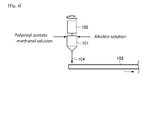
- Fig. 4 is a view illustrating a conventional saponification method using a belt reactor.
- a methanol solution of polyvinyl acetate and an alkaline solution are first placed in a mixing container 101 and agitated for example in a rotor mixer (mixer) 102 for a particular time.
- the mixture 104 is then placed on a belt 103, where the saponification reaction is allowed to proceed under a particular temperature condition.
- Patent Documents 1 and 2 Also proposed conventionally were methods wherein a liquid (slurry) for saponification reaction containing a polyvinyl ester and an organic solvent and a saponification catalyst are mixed in a kneader and the saponification reaction is then allowed to proceed in a tower-type saponification reactor (see Patent Documents 1 and 2). Also proposed are a method of mixing a polyvinyl ester solution and a saponification catalyst in an in-line mixer and saponifying the polyvinyl ester in a reactor equipped with a planetary stirrer (see Patent Document 3) and an apparatus having a static mixer in a rector for saponification (see Patent Document 4).
- a main object of the present invention is to provide a method and an apparatus for production of polyvinyl alcohol that can reduce energy consumption without deterioration in quality.
- the method of producing a polyvinyl alcohol resin according to the present invention includes an introducing step of introducing a saponification catalyst to the center of a channel for flow of a raw saponification solution containing a polyvinyl ester and an organic solvent and a mixing step of mixing the raw saponification solution and the introduced saponification catalyst by static mixer. Because the raw materials are mixed by the static mixer in the present invention, no energy is needed for the mixing. In addition, the mixing by the static mixer does not generate heat, thus preventing progress of the saponification reaction during mixing. Therefore, the polyvinyl alcohol resin produced has more stabilized quality.
- the saponification catalyst is introduced to the center of the channel for flow of the raw saponification solution, the mixing efficiency is higher and the raw saponification solution and the catalyst can be mixed in a shorter period of time.
- the mixture obtained from the mixing step can be subjected to saponification reaction, as it is placed on a belt.
- the concentration of polyvinyl ester in the raw saponification solution may be adjusted to 20 to 60 mass % and the viscosity thereof to 0.01 to 30 Pa ⁇ s before introduction of the saponification catalyst into the raw saponification solution to a catalyst concentration of 0.2 to 10 mass % in the raw saponification solution.
- the apparatus for producing a polyvinyl alcohol resin according to the present invention includes a catalyst-introducing mechanism for introducing a saponification catalyst to the center of a channel for flow of the raw saponification solution containing a polyvinyl ester and an organic solvent and one or more static mixers installed downstream of the catalyst-introducing mechanism for mixing the raw saponification solution with the introduced saponification catalyst. Because static mixers are used as the mixers in the present invention, there is no need for the power for operation of the mixers. Additionally, the static mixers do not generate mixing heat, thus preventing progress of the saponification reaction during mixing and stabilizing the quality of the product. Further because the catalyst is introduced into the center of the channel by the catalyst-introducing mechanism, the mixture can be mixed favorably in a short period of time.
- the apparatus may contain static mixers having a pressure drop per element of less than 0.05 MPa.
- the apparatus may have a unidirectionally moving belt and, in such a case, the saponification reaction may be allowed to proceed, as the mixture discharged from the static mixer is placed thereon.
- the catalyst-introducing mechanism may have an introducing pipe for flow of the catalyst-containing solution which is formed, as it crosses the center of the channel and extends through the channel in the direction perpendicular to the flow direction, and an introduction port having an opening facing the static mixer which is formed at the position of the introducing pipe equivalent to the center of the channel.
- the present invention wherein a saponification catalyst is introduced into the center of a channel for flow of a raw saponification solution containing a polyvinyl ester and an organic solvent and the mixture is mixed by a static mixer, can reduce energy consumption without deterioration in quality of the polyvinyl alcohol resin produced.
- a PVA resin is produced in a polymerization step and a saponification step shown below.
- a polyvinyl ester is prepared by polymerization of one or more vinyl esters or by copolymerization of a vinyl ester with other monomers copolymerizable therewith.
- the vinyl esters for use include, for example, vinyl formate, vinyl acetate, vinyl propionate, vinyl valerate, vinyl caproate, vinyl laurate, vinyl stearate, vinyl benzoate, vinyl pivalate and vinyl versatate, but vinyl acetate is preferable from the viewpoint of polymerization stability.
- vinyl esters include, but are not particularly limited to, for example, ⁇ -olefins such as ethylene and propylene; alkyl (meth)acrylate esters such as methyl (meth)acrylate, ethyl (meth)acrylate, butyl (meth)acrylate and 2-ethylhexyl (meth)acrylate; unsaturated amides such as (meth)acrylamide and N-methylol acrylamide; unsaturated acids such as (meth)acrylic acid, crotonic acid, maleic acid, itaconic acid and fumaric acid; unsaturated acid alkyl (such as methyl, ethyl and propyl) esters; unsaturated acid anhydrides such as maleic anhydride; unsaturated acid salts (such as sodium salts, potassium salts, ammonium salts, etc.); glycidyl group-containing monomers such as allyl glycidylether and g
- the polyvinyl ester obtained in the polymerization step described above is then saponified in an organic solvent in the presence of a catalyst.
- Alcohols such as methanol, ethanol, propanol, ethylene glycol, propylene glycol, glycerol and diethylene glycol can be used as the organic solvents for use, but methanol is particularly preferable.
- the saponification catalysts include alkali catalysts such as sodium hydroxide, potassium hydroxide, sodium alcoholate and sodium carbonate and acid catalysts such as sulfuric acid, phosphoric acid and hydrochloric acid.
- alkali catalysts such as sodium hydroxide, potassium hydroxide, sodium alcoholate and sodium carbonate
- acid catalysts such as sulfuric acid, phosphoric acid and hydrochloric acid.
- use of an alkali catalyst is preferable and use of sodium hydroxide is more preferable. It is thus possible to raise saponification rate and improve productivity.
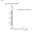
- Fig. 1 is a schematic view illustrating the configuration of a saponification apparatus used in a method of producing a PVA resin in the present embodiment.
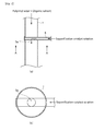
- Fig. 2(a) is a sectional view illustrating a configuration example of catalyst-introducing mechanism therein and Fig. 2(b) is a crosssectional view taken along the line A-A shown in Fig. 2(a) .
- a raw saponification solution containing a polyvinyl ester which was obtained in the polymerization step, and an organic solvent is fed into a channel 1 and a saponification catalyst-containing solution is introduced to the center of the stream. They are then mixed by a static mixer 2 and the resulting mixture 4 is subjected to saponification reaction, as it is placed, for example, on a belt 3.
- the viscosity of the raw saponification solution then is preferably 0.01 to 30 Pa ⁇ s. It is because the amount of the solvent used increases, thus leading to increase of the production cost, when the viscosity of the raw saponification solution is less than 0.01 Pa ⁇ s and it becomes difficult to feed the raw saponification solution when the viscosity thereof is more than 30 Pa ⁇ s.
- the concentration of the polyvinyl ester in the raw saponification solution is preferably 20 to 60 mass %.
- a polyvinyl ester concentration of less than 20 mass % makes the reaction proceed easily, because of the decrease in solution viscosity, it also demands use of a greater amount of the solvent, leading to increase in the production cost of the PVA resin.
- a polyvinyl ester concentration of more than 60 mass % may make it difficult to feed the solution because of high viscosity.
- the concentration of the saponification catalyst in the saponification catalyst solution is preferably 0.2 to 10 mass %. It is because the reaction rate may decline when the saponification catalyst concentration is less than 0.2 mass % and neutralization reaction after the reaction may generate a great amount of salts, demanding a great amount of washing liquid in a washing step, when the saponification catalyst concentration is more than 10 mass %.
- a saponification catalyst-introducing pipe 5 having an introduction port 5a is made to extend through the channel 1 in the direction perpendicular to a flow direction with the introduction port 5a facing downstream in the flow direction in the center of the channel 2.
- the saponification catalyst-introducing pipe 5 is made to extend through the channel in order to reduce as much as possible fluctuation in flow rate at various points in the cross section perpendicular to the flow direction of the channel 1 and generation of turbulence of the stream of the raw saponification solution.
- the saponification catalyst solution is introduced into the center of the channel 1 for the purpose of improving the mixing efficiency. If the saponification catalyst solution is introduced to a point separated from the center of the channel 1, fluctuation in concentration occurs at various points in the cross section perpendicular to the flow direction.
- the size of the introduction port 5a is not particularly limited, but desirably 1/20 to 1/2 of the diameter of the channel 1. It is possible, by the catalyst-introducing mechanism installed in such a configuration, to reduce turbulence of the stream of the raw saponification solution and to mix the raw materials efficiently.
- the method of introducing the saponification catalyst solution is not limited to that shown in Fig. 2 and can be selected properly for example in accordance with the desired system configuration.
- the saponification catalyst-introducing pipe 5 may be a cantilevered L-shaped pipe, or the saponification catalyst-introducing pipe 5 may be a cross-shaped pipe having an introduction port 5a at the center.
- the kind and the number of the static mixers 2 are not particularly limited and can be selected properly in accordance with various conditions such as flow quantity, flow rate and concentration.
- Use of a static mixer 2 showing a pressure drop per element of less than 0.05 MPa is preferable. It is thus possible to install multiple elements (static mixers) without need for expensive high-allowable pressure pumps and to obtain a favorable mixing state (CoV: 0.01 or less) at an energy less than that before by using existing facilities.
- the pressure drop per element by the static mixer 2 is more preferably less than 0.03 MPa. It is thus possible to increase the number of the static mixers 2 used and to raise the mixing efficiency. If the number of the static mixers 2 (elements) used is increased, although the mixing efficiency increases, the pressure drop also increases. Thus, the diameter thereof is preferably selected properly in accordance with the allowable pressures of the raw material-feeding pump and the supply pipe.
- multiple types of static mixers showing different pressure drops may be used in combination.
- Shear rate and pressure drop are in the relationship of tradeoff and, for example, it is needed to reduce the diameter of the static mixer to obtain higher shear rate, but smaller diameter also leads to increase in pressure drop. Even in such a case, it is possible to suppress increase in pressure drop and yet raise shear rate, by using multiple types of static mixers showing different pressure drops and controlling the installation ratio thereof so as to make the pressures applied to respective pumps lower than their allowable pressures.
- the mixture 4 obtained after mixing by the static mixer 2 is left for saponification reaction under a particular temperature condition for a particular time.
- a particular temperature condition for a particular time For example in the case of the belt reactor shown in Fig. 1 , the mixture is left under a temperature condition of 20 to 50°C, as the belt 3 is driven.
- the retention time then can be determined in accordance with the desired saponification degree and is, for example, about 30 minutes if an average saponification degree of about 90 mole % is desired.
- the present invention is not limited to use of a belt reactor and, for example, a kneader-or tower-type reactor can also be used instead of the belt reactor.
- the saponification step part or all of the vinyl ester groups in the polyvinyl ester are saponificated to vinyl alcohol groups.
- the saponification degree of the PVA resin obtained in the saponification step described above is not particularly limited and may be determined arbitrarily, for example, according to its application.
- a washing step for removal of impurities such as sodium acetate and a drying step may be carried out, as needed, after the polymerization and saponification steps above.
- a saponification catalyst-containing solution is introduced to the center of the channel for flow of the raw saponification solution containing a polyvinyl ester and an organic solvent, it is possible to obtain favorable mixing state in a short period of time even when a static mixer is used. Consequently, it is possible to reduce the energy needed for production without deterioration in quality of the PVA resin produced.
- a polyvinyl acetate obtained in a polymerization step is saponified in a belt reactor equipped with the static mixer 2 shown in Fig. 1 (Examples) or in a belt reactor equipped with the rotor mixer 102 shown in Fig. 4 (Comparative Example), to give a polyvinyl alcohol (PVA) resin.
- PVA polyvinyl alcohol
- a raw saponification solution i.e., polyvinyl acetate-methanol solution (concentration: 37.5 mass %) and a saponification catalyst solution, i.e., sodium hydroxide-methanol solution (concentration: 3 mass %) were mixed under the condition shown in the following Table 1, by using two kinds of static mixer A (high pressure drop) and B (low pressure drop) different in pressure drop per element.
- a saponification catalyst solution i.e., sodium hydroxide-methanol solution (concentration: 3 mass %)
- Comparative Example 1 a polyvinyl acetate-methanol solution (concentration: 37.5 mass %) and a sodium hydroxide-methanol solution (concentration: 1.5 mass %) were mixed under the condition shown in the following Table 1 at a rotational frequency of 650 rpm by using a rotor mixer consisting of a casing and a pin, which is used as the rotor.
- the viscosity shown in Table 1 was determined by using a CVO rheometer under the condition of: mode: viscometry-mode multi-shear rate measurement, temperature: 40°C, concentration: 37.5 mass %, cone: CP4°/40 mm, shear rate: 1 to 1000 s -1 , Delay: 5 to 15 seconds and integration: 10 seconds.
- the motor power is a value calculated, as the motor efficiency is estimated as 0.6.
- the CoV Coefficient of Variation
- the saponification degree distribution of the PVA resins of Example 1 and Comparative Example 1 was determined by infrared spectroscopy (IR). Specifically, IR absorption by each of 50 arbitrarily chosen PVA particles was determined by using an FT-IR8400 apparatus manufactured by Shimadzu Corporation equipped with a single-reflection total reflection analyzer (ZnSe prism) and the saponification degree of each particle was calculated according to the formula shown by the following mathematical expression 1: D 1730 in the following expression 1 is the absorbance at a wave number of 1730 cm -1 and D 844 at a wave number of 844 cm -1 .
- IR absorption by each of 50 arbitrarily chosen PVA particles was determined by using an FT-IR8400 apparatus manufactured by Shimadzu Corporation equipped with a single-reflection total reflection analyzer (ZnSe prism) and the saponification degree of each particle was calculated according to the formula shown by the following mathematical expression 1: D 1730 in the following expression 1 is the absorbance at a wave number of 1730 cm
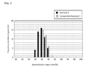
- Fig. 3 is a histogram showing distribution of the saponification degrees of the PVA resins in Example 1 and Comparative Example 1, wherein the saponification degrees are plotted on the abscissa and the frequency on the ordinate. As shown in Fig. 3 , even when a static mixer is used for mixing, a PVA resin having a saponification degree distribution equivalent to that when a rotor mixer is used was obtained.
Landscapes
- Chemical & Material Sciences (AREA)
- Health & Medical Sciences (AREA)
- Chemical Kinetics & Catalysis (AREA)
- Medicinal Chemistry (AREA)
- Polymers & Plastics (AREA)
- Organic Chemistry (AREA)
- General Chemical & Material Sciences (AREA)
- Addition Polymer Or Copolymer, Post-Treatments, Or Chemical Modifications (AREA)
Abstract
Description
- The present invention relates to a method and an apparatus for producing a polyvinyl alcohol resin. More specifically, it relates to a technology concerning the saponification step carried out in production of a polyvinyl alcohol resin.
- Polyvinyl alcohol (PVA), a water-soluble synthetic resin, has been used mainly as a raw material for synthetic fibers. Recently, it is used in various fields, for example for production of film materials, emulsifying dispersants, adhesives and binder resins, because of its favorable properties. The PVA resins are generally produced by polymerization of a vinyl ester and saponification of the resulting polyvinyl ester in an organic solvent in the presence of a catalyst.
- For saponification of the polyvinyl ester then, for example, a belt reactor equipped with an in-line mixer is used.
Fig. 4 is a view illustrating a conventional saponification method using a belt reactor. As shown inFig. 4 , when PVA is produced by saponification of polyvinyl acetate in methanol solvent in the presence of an alkali catalyst in a conventional belt reactor, a methanol solution of polyvinyl acetate and an alkaline solution are first placed in amixing container 101 and agitated for example in a rotor mixer (mixer) 102 for a particular time. Themixture 104 is then placed on abelt 103, where the saponification reaction is allowed to proceed under a particular temperature condition. - Also proposed conventionally were methods wherein a liquid (slurry) for saponification reaction containing a polyvinyl ester and an organic solvent and a saponification catalyst are mixed in a kneader and the saponification reaction is then allowed to proceed in a tower-type saponification reactor (see
Patent Documents 1 and 2). Also proposed are a method of mixing a polyvinyl ester solution and a saponification catalyst in an in-line mixer and saponifying the polyvinyl ester in a reactor equipped with a planetary stirrer (see Patent Document 3) and an apparatus having a static mixer in a rector for saponification (see Patent Document 4). -
- [Patent Document 1] Japanese Unexamined Patent Application Publication No.
2000-355611 - [Patent Document 2] Japanese Unexamined Patent Application Publication No.
2001-55414 - [Patent Document 3] Japanese Translation of
PCT No. 2008-510880 - [Patent Document 4] International Patent Application Publication No.
WO 2003/033548 - However, conventional saponification methods described above have the following disadvantages. Namely, they have a disadvantage that methods using a mixer demanding high power, such as rotor mixer, kneader or planetary stirrer, are higher in energy consumption. Alternatively when a static mixer is used as the mixer, as in the apparatus described in
Patent Document 4, it is possible to reduce energy consumption, but not possible to mix the raw materials uniformly only by installing a static mixer in the reactor. Yet alternatively, the technology described inPatent Document 4 has a disadvantage that it demands a pressure-resistant apparatus because a supercritical or high-temperature high-pressure fluid is used. - Accordingly, a main object of the present invention is to provide a method and an apparatus for production of polyvinyl alcohol that can reduce energy consumption without deterioration in quality.
- The method of producing a polyvinyl alcohol resin according to the present invention includes an introducing step of introducing a saponification catalyst to the center of a channel for flow of a raw saponification solution containing a polyvinyl ester and an organic solvent and a mixing step of mixing the raw saponification solution and the introduced saponification catalyst by static mixer.
Because the raw materials are mixed by the static mixer in the present invention, no energy is needed for the mixing. In addition, the mixing by the static mixer does not generate heat, thus preventing progress of the saponification reaction during mixing. Therefore, the polyvinyl alcohol resin produced has more stabilized quality. Further because the saponification catalyst is introduced to the center of the channel for flow of the raw saponification solution, the mixing efficiency is higher and the raw saponification solution and the catalyst can be mixed in a shorter period of time.
In this production method, the mixture obtained from the mixing step can be subjected to saponification reaction, as it is placed on a belt.
The concentration of polyvinyl ester in the raw saponification solution may be adjusted to 20 to 60 mass % and the viscosity thereof to 0.01 to 30 Pa ·s before introduction of the saponification catalyst into the raw saponification solution to a catalyst concentration of 0.2 to 10 mass % in the raw saponification solution. - The apparatus for producing a polyvinyl alcohol resin according to the present invention includes a catalyst-introducing mechanism for introducing a saponification catalyst to the center of a channel for flow of the raw saponification solution containing a polyvinyl ester and an organic solvent and one or more static mixers installed downstream of the catalyst-introducing mechanism for mixing the raw saponification solution with the introduced saponification catalyst.
Because static mixers are used as the mixers in the present invention, there is no need for the power for operation of the mixers. Additionally, the static mixers do not generate mixing heat, thus preventing progress of the saponification reaction during mixing and stabilizing the quality of the product. Further because the catalyst is introduced into the center of the channel by the catalyst-introducing mechanism, the mixture can be mixed favorably in a short period of time.
The apparatus may contain static mixers having a pressure drop per element of less than 0.05 MPa.
In addition, the apparatus may have a unidirectionally moving belt and, in such a case, the saponification reaction may be allowed to proceed, as the mixture discharged from the static mixer is placed thereon.
Further, the catalyst-introducing mechanism may have an introducing pipe for flow of the catalyst-containing solution which is formed, as it crosses the center of the channel and extends through the channel in the direction perpendicular to the flow direction, and an introduction port having an opening facing the static mixer which is formed at the position of the introducing pipe equivalent to the center of the channel. - The present invention, wherein a saponification catalyst is introduced into the center of a channel for flow of a raw saponification solution containing a polyvinyl ester and an organic solvent and the mixture is mixed by a static mixer, can reduce energy consumption without deterioration in quality of the polyvinyl alcohol resin produced.
-
-
Fig. 1 is a schematic view illustrating the configuration of a saponification apparatus used in a method of producing a polyvinyl alcohol resin according to an embodiment of the present invention. -
Fig. 2(a) is a sectional view illustrating a configuration example of a catalyst-introducing mechanism in the saponification apparatus shown inFig. 1 andFig. 2(b) is a crosssectional view taken along the line A-A inFig. 2(a) . -
Fig. 3 is a histogram showing distribution of the saponification degrees of the PVA resins in Example 1 and Comparative Example 1, the saponification degrees being plotted on the abscissa and the frequency on the ordinate. -
Fig. 4 is a view illustrating a conventional saponification method using a belt reactor. - Hereinafter, favorable embodiments of the present invention will be described in detail with reference to attached drawings. It should be understood that the present invention is not restricted by the embodiments described below. In the method of producing a polyvinyl alcohol (PVA) resin according to an embodiment of the present invention, a PVA resin is produced in a polymerization step and a saponification step shown below.
- In the method of producing a polyvinyl alcohol resin in the present embodiment, a polyvinyl ester is prepared by polymerization of one or more vinyl esters or by copolymerization of a vinyl ester with other monomers copolymerizable therewith. The vinyl esters for use include, for example, vinyl formate, vinyl acetate, vinyl propionate, vinyl valerate, vinyl caproate, vinyl laurate, vinyl stearate, vinyl benzoate, vinyl pivalate and vinyl versatate, but vinyl acetate is preferable from the viewpoint of polymerization stability.
- Other monomers copolymerizable with these vinyl esters include, but are not particularly limited to, for example, α-olefins such as ethylene and propylene; alkyl (meth)acrylate esters such as methyl (meth)acrylate, ethyl (meth)acrylate, butyl (meth)acrylate and 2-ethylhexyl (meth)acrylate; unsaturated amides such as (meth)acrylamide and N-methylol acrylamide; unsaturated acids such as (meth)acrylic acid, crotonic acid, maleic acid, itaconic acid and fumaric acid; unsaturated acid alkyl (such as methyl, ethyl and propyl) esters; unsaturated acid anhydrides such as maleic anhydride; unsaturated acid salts (such as sodium salts, potassium salts, ammonium salts, etc.); glycidyl group-containing monomers such as allyl glycidylether and glycidyl (meth)acrylate; sulfonic acid group-containing monomer such as 2-acrylamido-2- methylpropanesulfonic acid and the salts thereof; phosphate group-containing monomers such as acid phosphoxyethyl methacrylate and acid phosphoxypropyl methacrylate; alkyl vinylethers and the like.
- The polyvinyl ester obtained in the polymerization step described above is then saponified in an organic solvent in the presence of a catalyst. Alcohols such as methanol, ethanol, propanol, ethylene glycol, propylene glycol, glycerol and diethylene glycol can be used as the organic solvents for use, but methanol is particularly preferable.
- Examples of the saponification catalysts include alkali catalysts such as sodium hydroxide, potassium hydroxide, sodium alcoholate and sodium carbonate and acid catalysts such as sulfuric acid, phosphoric acid and hydrochloric acid. Among the saponification catalysts above, use of an alkali catalyst is preferable and use of sodium hydroxide is more preferable. It is thus possible to raise saponification rate and improve productivity.
-
Fig. 1 is a schematic view illustrating the configuration of a saponification apparatus used in a method of producing a PVA resin in the present embodiment.Fig. 2(a) is a sectional view illustrating a configuration example of catalyst-introducing mechanism therein andFig. 2(b) is a crosssectional view taken along the line A-A shown inFig. 2(a) . In the method of producing a PVA resin according to the present embodiment, for example as shown inFigs. 1 and2 , a raw saponification solution containing a polyvinyl ester, which was obtained in the polymerization step, and an organic solvent is fed into achannel 1 and a saponification catalyst-containing solution is introduced to the center of the stream. They are then mixed by astatic mixer 2 and the resultingmixture 4 is subjected to saponification reaction, as it is placed, for example, on abelt 3. - The viscosity of the raw saponification solution then is preferably 0.01 to 30 Pa ·s. It is because the amount of the solvent used increases, thus leading to increase of the production cost, when the viscosity of the raw saponification solution is less than 0.01 Pa ·s and it becomes difficult to feed the raw saponification solution when the viscosity thereof is more than 30 Pa ·s.
- The concentration of the polyvinyl ester in the raw saponification solution is preferably 20 to 60 mass %. Although a polyvinyl ester concentration of less than 20 mass % makes the reaction proceed easily, because of the decrease in solution viscosity, it also demands use of a greater amount of the solvent, leading to increase in the production cost of the PVA resin. Alternatively, a polyvinyl ester concentration of more than 60 mass % may make it difficult to feed the solution because of high viscosity.
- Alternatively, the concentration of the saponification catalyst in the saponification catalyst solution is preferably 0.2 to 10 mass %. It is because the reaction rate may decline when the saponification catalyst concentration is less than 0.2 mass % and neutralization reaction after the reaction may generate a great amount of salts, demanding a great amount of washing liquid in a washing step, when the saponification catalyst concentration is more than 10 mass %.
- As for the method of introducing the saponification catalyst solution into the center of the
channel 1, for example, as shown inFig. 2 , a saponification catalyst-introducingpipe 5 having anintroduction port 5a is made to extend through thechannel 1 in the direction perpendicular to a flow direction with theintroduction port 5a facing downstream in the flow direction in the center of thechannel 2. The saponification catalyst-introducingpipe 5 is made to extend through the channel in order to reduce as much as possible fluctuation in flow rate at various points in the cross section perpendicular to the flow direction of thechannel 1 and generation of turbulence of the stream of the raw saponification solution. - The saponification catalyst solution is introduced into the center of the
channel 1 for the purpose of improving the mixing efficiency. If the saponification catalyst solution is introduced to a point separated from the center of thechannel 1, fluctuation in concentration occurs at various points in the cross section perpendicular to the flow direction. The size of theintroduction port 5a is not particularly limited, but desirably 1/20 to 1/2 of the diameter of thechannel 1. It is possible, by the catalyst-introducing mechanism installed in such a configuration, to reduce turbulence of the stream of the raw saponification solution and to mix the raw materials efficiently. - The method of introducing the saponification catalyst solution is not limited to that shown in
Fig. 2 and can be selected properly for example in accordance with the desired system configuration. For example, the saponification catalyst-introducingpipe 5 may be a cantilevered L-shaped pipe, or the saponification catalyst-introducingpipe 5 may be a cross-shaped pipe having anintroduction port 5a at the center. - Alternatively, the kind and the number of the
static mixers 2 are not particularly limited and can be selected properly in accordance with various conditions such as flow quantity, flow rate and concentration. Use of astatic mixer 2 showing a pressure drop per element of less than 0.05 MPa is preferable. It is thus possible to install multiple elements (static mixers) without need for expensive high-allowable pressure pumps and to obtain a favorable mixing state (CoV: 0.01 or less) at an energy less than that before by using existing facilities. - The pressure drop per element by the
static mixer 2 is more preferably less than 0.03 MPa. It is thus possible to increase the number of thestatic mixers 2 used and to raise the mixing efficiency. If the number of the static mixers 2 (elements) used is increased, although the mixing efficiency increases, the pressure drop also increases. Thus, the diameter thereof is preferably selected properly in accordance with the allowable pressures of the raw material-feeding pump and the supply pipe. - In the saponification apparatus used in the method of producing a PVA resin according to the present embodiment, multiple types of static mixers showing different pressure drops may be used in combination. Shear rate and pressure drop are in the relationship of tradeoff and, for example, it is needed to reduce the diameter of the static mixer to obtain higher shear rate, but smaller diameter also leads to increase in pressure drop. Even in such a case, it is possible to suppress increase in pressure drop and yet raise shear rate, by using multiple types of static mixers showing different pressure drops and controlling the installation ratio thereof so as to make the pressures applied to respective pumps lower than their allowable pressures.
- The
mixture 4 obtained after mixing by thestatic mixer 2 is left for saponification reaction under a particular temperature condition for a particular time. For example in the case of the belt reactor shown inFig. 1 , the mixture is left under a temperature condition of 20 to 50°C, as thebelt 3 is driven. The retention time then can be determined in accordance with the desired saponification degree and is, for example, about 30 minutes if an average saponification degree of about 90 mole % is desired. The present invention is not limited to use of a belt reactor and, for example, a kneader-or tower-type reactor can also be used instead of the belt reactor. - In the saponification step, part or all of the vinyl ester groups in the polyvinyl ester are saponificated to vinyl alcohol groups. The saponification degree of the PVA resin obtained in the saponification step described above is not particularly limited and may be determined arbitrarily, for example, according to its application.
- Also in the method of producing a PVA resin according to the present embodiment, a washing step for removal of impurities such as sodium acetate and a drying step may be carried out, as needed, after the polymerization and saponification steps above.
- As described above in detail, in the method of producing a polyvinyl alcohol resin according to the present embodiment, there is no need for the power for mixing, because the raw saponification solution and the saponification catalyst solution are mixed by a static mixer. It is thus possible to reduce the energy consumption considerably in the saponification step. In addition, because the static mixer does not generate mixing heat, no saponification reaction proceeds during mixing. Accordingly, it is possible to stabilize the quality of the PVA resin produced.
- Further in the method of producing a PVA resin according to the present embodiment, because a saponification catalyst-containing solution is introduced to the center of the channel for flow of the raw saponification solution containing a polyvinyl ester and an organic solvent, it is possible to obtain favorable mixing state in a short period of time even when a static mixer is used. Consequently, it is possible to reduce the energy needed for production without deterioration in quality of the PVA resin produced.
- Hereinafter, the advantageous effects of the present invention will be described specifically with reference to Examples and Comparative Examples of the present invention. In each of the Examples, a polyvinyl acetate obtained in a polymerization step is saponified in a belt reactor equipped with the
static mixer 2 shown inFig. 1 (Examples) or in a belt reactor equipped with therotor mixer 102 shown inFig. 4 (Comparative Example), to give a polyvinyl alcohol (PVA) resin. - Specifically, in Examples 1 to 5, a raw saponification solution, i.e., polyvinyl acetate-methanol solution (concentration: 37.5 mass %) and a saponification catalyst solution, i.e., sodium hydroxide-methanol solution (concentration: 3 mass %) were mixed under the condition shown in the following Table 1, by using two kinds of static mixer A (high pressure drop) and B (low pressure drop) different in pressure drop per element. On the other hand, in Comparative Example 1, a polyvinyl acetate-methanol solution (concentration: 37.5 mass %) and a sodium hydroxide-methanol solution (concentration: 1.5 mass %) were mixed under the condition shown in the following Table 1 at a rotational frequency of 650 rpm by using a rotor mixer consisting of a casing and a pin, which is used as the rotor.
-
[Table 1] Comparative Example 1 Example 1 Example 2 Example 3 Example 4 Example 5 Kind of mixer Rotor mixer Static mixer A Static mixer B Static mixer A Static mixer A Static mixer A Number of elements (units) - 16 20 20 15 10 Feed rate (liter/hour) Raw saponification solution 5106 5106 7323 7323 7323 7323 Saponification catalyst solution 606 606 844 844 844 844 Shear rate (1/s) - 350 400 500 500 500 Temperature of raw saponification solution at inlet port (°C) 35 38 42 42 42 42 Mixing heat ΔT (°C) 4 0 0 0 0 0 Viscosity (Pa ·s) Before mixing 5.4 5.4 5.3 5.1 5.1 5.1 After mixing 3.3 3.3 3.2 3.1 3.1 3.1 Motor power (kW) 33 - - - - - CoV - 0.0075 0.0012 0.0012 0.012 0.12 Pressure drop (MPa) 0.51 0.63 0.52 0.94 0.73 0.52 Residence time (sec) 6.9 2.1 1.7 1.8 1.4 0.9 - The viscosity shown in Table 1 was determined by using a CVO rheometer under the condition of: mode: viscometry-mode multi-shear rate measurement, temperature: 40°C, concentration: 37.5 mass %, cone: CP4°/40 mm, shear rate: 1 to 1000 s-1, Delay: 5 to 15 seconds and integration: 10 seconds. The motor power is a value calculated, as the motor efficiency is estimated as 0.6. In addition, the CoV (Coefficient of Variation) is the deviation constant

- The mixture prepared by the method under the condition described above was then placed on a
belt - The saponification degree distribution of the PVA resins of Example 1 and Comparative Example 1 was determined by infrared spectroscopy (IR). Specifically, IR absorption by each of 50 arbitrarily chosen PVA particles was determined by using an FT-IR8400 apparatus manufactured by Shimadzu Corporation equipped with a single-reflection total reflection analyzer (ZnSe prism) and the saponification degree of each particle was calculated according to the formula shown by the following mathematical expression 1: D1730 in the following
expression 1 is the absorbance at a wave number of 1730 cm-1 and D844 at a wave number of 844 cm-1. -

-
Fig. 3 is a histogram showing distribution of the saponification degrees of the PVA resins in Example 1 and Comparative Example 1, wherein the saponification degrees are plotted on the abscissa and the frequency on the ordinate. As shown inFig. 3 , even when a static mixer is used for mixing, a PVA resin having a saponification degree distribution equivalent to that when a rotor mixer is used was obtained. - If a rotor mixer is assumed to operate for 8000 hours a year, because the motor power is 33 kW, as shown in Table 1, the annual power consumption is about 260 MWH. In contrast when the mixer is replaced with static mixers, all of the power consumption can be eliminated. In addition as shown in Table 1, a mixing heat of 4°C was generated in the case of mixing with a rotor mixer, but the mixing heat was not generated when the mixing is carried out with static mixers.
- The results above show that it is possible to produce a PVA resin at a quality no lower than that of conventional products with an energy consumption smaller than that before, by using static mixers as the mixer and introducing a saponification catalyst solution into the center of the channel for flow of a raw saponification solution.
-
- 1:
- Channel
- 2:
- Static mixer
- 3, 103:
- Belt
- 4, 104:
- Mixture
- 5:
- Saponification catalyst-introducing pipe
- 5a:
- Introduction port
- 101:
- Mixing container
- 102:
- Rotor mixer
Claims (7)
- A method of producing a polyvinyl alcohol resin, comprising:an introducing step of introducing a saponification catalyst to the center of a channel for flow of a raw saponification solution containing a polyvinyl ester and an organic solvent; anda mixing step of mixing the raw saponification solution and the introduced saponification catalyst by static mixer.
- The method of producing a polyvinyl alcohol resin according to Claim 1, wherein the mixture obtained in the mixing step is subjected to saponification reaction, as it is placed on a belt.
- The method of producing a polyvinyl alcohol resin according to Claim 1 or 2, wherein the concentration of the polyvinyl ester in the raw saponification solution is 20 to 60 mass %, the viscosity is 0.01 to 30 Pa ·s, and the saponification catalyst is introduced into the raw saponification solution to a catalyst concentration of 0.2 to 10 mass %.
- An apparatus for producing a polyvinyl alcohol resin, comprising:a catalyst-introducing mechanism for introducing a saponification catalyst to the center of a channel for flow of a raw saponification solution containing a polyvinyl ester and an organic solvent; andone or more static mixers installed downstream of the catalyst-introducing mechanism for mixing the raw saponification solution with the introduced saponification catalyst.
- The apparatus for producing a polyvinyl alcohol resin according to Claim 4, wherein the static mixer shows a pressure drop per element of less than 0.05 MPa.
- The apparatus for producing a polyvinyl alcohol resin according to Claim 4 or 5, further comprising a belt movable unidirectionally, wherein the mixture discharged from the static mixer is subjected to saponification reaction, as it is placed on the belt.
- The apparatus for producing a polyvinyl alcohol resin according to any one of Claims 4 to 6, wherein the catalyst-introducing mechanism has an introducing pipe for flow of the catalyst-containing solution which is formed, as it crosses the center of the channel and extends through the channel in the direction perpendicular to the flow direction, and an introduction port having an opening facing the static mixer which is formed at the position of the introducing pipe equivalent to the center of the channel.
Applications Claiming Priority (2)
| Application Number | Priority Date | Filing Date | Title |
|---|---|---|---|
| JP2010062768A JP5545723B2 (en) | 2010-03-18 | 2010-03-18 | Production method and production apparatus for polyvinyl alcohol resin |
| PCT/JP2010/070174 WO2011114575A1 (en) | 2010-03-18 | 2010-11-12 | Production method and production device for polyvinyl alcohol resins |
Publications (3)
| Publication Number | Publication Date |
|---|---|
| EP2548898A1 true EP2548898A1 (en) | 2013-01-23 |
| EP2548898A4 EP2548898A4 (en) | 2014-11-26 |
| EP2548898B1 EP2548898B1 (en) | 2016-08-24 |
Family
ID=44648694
Family Applications (1)
| Application Number | Title | Priority Date | Filing Date |
|---|---|---|---|
| EP10847981.7A Active EP2548898B1 (en) | 2010-03-18 | 2010-11-12 | Production method and production device for polyvinyl alcohol resins |
Country Status (8)
| Country | Link |
|---|---|
| US (1) | US9023287B2 (en) |
| EP (1) | EP2548898B1 (en) |
| JP (1) | JP5545723B2 (en) |
| CN (1) | CN102812054B (en) |
| ES (1) | ES2597602T3 (en) |
| SG (1) | SG184053A1 (en) |
| TW (1) | TW201132651A (en) |
| WO (1) | WO2011114575A1 (en) |
Cited By (3)
| Publication number | Priority date | Publication date | Assignee | Title |
|---|---|---|---|---|
| JP2016020436A (en) * | 2014-07-14 | 2016-02-04 | 株式会社クラレ | Polyvinyl alcohol and aqueous emulsion |
| JP2016020435A (en) * | 2014-07-14 | 2016-02-04 | 株式会社クラレ | Ethylene modified polyvinyl alcohol and aqueous emulsion |
| EP3153531A1 (en) | 2014-06-04 | 2017-04-12 | Kuraray Co., Ltd. | Polyvinyl alcohol powder and method for producing same |
Families Citing this family (10)
| Publication number | Priority date | Publication date | Assignee | Title |
|---|---|---|---|---|
| JP6122579B2 (en) * | 2012-05-17 | 2017-04-26 | 積水化学工業株式会社 | Polyvinyl alcohol resin film material, method for producing polyvinyl alcohol resin film material, and method for producing polarizing film |
| MY195648A (en) * | 2014-07-14 | 2023-02-03 | Kuraray Co | Unmodified Polyvinyl Alcohol and Aqueous Emulsion |
| EP3190063B1 (en) * | 2014-09-01 | 2021-08-18 | Sekisui Chemical Co., Ltd. | Water-soluble packaging film |
| WO2016072179A1 (en) * | 2014-11-05 | 2016-05-12 | 日本酢ビ・ポバール株式会社 | Film-coating composition, solid oral formulation, and method for producing same |
| CN107108767B (en) * | 2014-12-26 | 2019-04-30 | 株式会社可乐丽 | Aqueous emulsions and adhesives using them |
| JP2017043872A (en) * | 2015-08-28 | 2017-03-02 | 株式会社クラレ | Paper coating agent |
| JP7517329B2 (en) * | 2019-03-29 | 2024-07-17 | 三菱ケミカル株式会社 | Method for producing polyvinyl alcohol resin |
| KR102743558B1 (en) * | 2019-09-03 | 2024-12-17 | 주식회사 엘지화학 | Method and System for Analyzing Saponification Distribution to Molecular Weight of Polyvinyl Alcohol |
| JP7471859B2 (en) * | 2020-02-27 | 2024-04-22 | 株式会社クラレ | Polyvinyl alcohol resin and underground treatment sealant |
| JP7604516B2 (en) * | 2020-11-11 | 2024-12-23 | 株式会社クラレ | Film for manufacturing optical film and method for manufacturing optical film |
Family Cites Families (8)
| Publication number | Priority date | Publication date | Assignee | Title |
|---|---|---|---|---|
| CA847445A (en) * | 1970-07-21 | Farbwerke Hoechst Aktiengesellschaft Vormals Meister Lucius And Bruning | Process for the manufacture of polyvinyl alcohol | |
| JPS4899290A (en) * | 1972-03-30 | 1973-12-15 | ||
| JPS5545562B2 (en) * | 1972-03-30 | 1980-11-18 | ||
| US4338405A (en) * | 1980-12-12 | 1982-07-06 | E. I. Du Pont De Nemours And Company | Process for continuous controlled alcoholysis of polyvinyl acetate |
| JP4717177B2 (en) | 1999-06-09 | 2011-07-06 | 株式会社クラレ | Method for producing polyvinyl alcohol polymer and polyvinyl alcohol polymer |
| JP2000355611A (en) | 1999-06-15 | 2000-12-26 | Kuraray Co Ltd | Tower type saponification reactor |
| EP1452549B1 (en) * | 2001-10-16 | 2010-11-17 | Sekisui Chemical Co., Ltd. | Process for producing modified polymer, apparatus for producing modified polymer, and modified polymer |
| KR100759188B1 (en) * | 2005-10-28 | 2007-09-14 | 주식회사 엘지화학 | Method for producing polyvinyl alcohol having high degree of polymerization and apparatus |
-
2010
- 2010-03-18 JP JP2010062768A patent/JP5545723B2/en active Active
- 2010-11-12 EP EP10847981.7A patent/EP2548898B1/en active Active
- 2010-11-12 ES ES10847981.7T patent/ES2597602T3/en active Active
- 2010-11-12 WO PCT/JP2010/070174 patent/WO2011114575A1/en not_active Ceased
- 2010-11-12 SG SG2012067914A patent/SG184053A1/en unknown
- 2010-11-12 US US13/634,331 patent/US9023287B2/en active Active
- 2010-11-12 CN CN201080065467.4A patent/CN102812054B/en active Active
- 2010-11-24 TW TW99140646A patent/TW201132651A/en unknown
Cited By (4)
| Publication number | Priority date | Publication date | Assignee | Title |
|---|---|---|---|---|
| EP3153531A1 (en) | 2014-06-04 | 2017-04-12 | Kuraray Co., Ltd. | Polyvinyl alcohol powder and method for producing same |
| EP3153531A4 (en) * | 2014-06-04 | 2018-02-14 | Kuraray Co., Ltd. | Polyvinyl alcohol powder and method for producing same |
| JP2016020436A (en) * | 2014-07-14 | 2016-02-04 | 株式会社クラレ | Polyvinyl alcohol and aqueous emulsion |
| JP2016020435A (en) * | 2014-07-14 | 2016-02-04 | 株式会社クラレ | Ethylene modified polyvinyl alcohol and aqueous emulsion |
Also Published As
| Publication number | Publication date |
|---|---|
| US9023287B2 (en) | 2015-05-05 |
| CN102812054B (en) | 2014-08-27 |
| CN102812054A (en) | 2012-12-05 |
| SG184053A1 (en) | 2012-10-30 |
| EP2548898B1 (en) | 2016-08-24 |
| EP2548898A4 (en) | 2014-11-26 |
| WO2011114575A1 (en) | 2011-09-22 |
| JP2011195672A (en) | 2011-10-06 |
| ES2597602T3 (en) | 2017-01-19 |
| TW201132651A (en) | 2011-10-01 |
| JP5545723B2 (en) | 2014-07-09 |
| US20120329950A1 (en) | 2012-12-27 |
Similar Documents
| Publication | Publication Date | Title |
|---|---|---|
| US9023287B2 (en) | Production method and production device for polyvinyl alcohol resins | |
| EP3031830B1 (en) | Dispersion stabilizer for suspension polymerization, and manufacturing method for vinyl resin | |
| US8308087B2 (en) | LDPE tubular reactor peroxide mixer | |
| CN110054727B (en) | Preparation method and device of polyacrylamide nano-microspheres | |
| WO2016009631A1 (en) | Polyvinyl alcohol, and aqueous emulsion, adhesive, and emulsion polymerization dispersant comprising same | |
| JP2022095976A (en) | Polyvinyl alcohol resin and method for producing the same | |
| CN105001357A (en) | Continuous preparation method for catalytically synthesizing polyvinyl butyral resin through organic acid | |
| EP1152032B1 (en) | Aqueous emulsion and method for suspension polymerization of vinyl compound | |
| CN102076403B (en) | For mixing arrangement and the method for continuous production of monomer emulsion | |
| CN112592418A (en) | Preparation method of polyvinyl alcohol special for optical film | |
| EP2548899A1 (en) | Production method and production device for polyvinyl alcohol | |
| JP7629018B2 (en) | Vinyl alcohol polymer | |
| US20160304632A1 (en) | Method for producing polyvinyl alcohol | |
| CN114573736B (en) | Method for reducing volatile matter content in poly (methyl) acrylic ester | |
| JP2011102341A (en) | Method for producing polyvinyl acetal | |
| EP3950872B1 (en) | Aqueous emulsion and adhesive using same | |
| CN113429557B (en) | Continuous preparation method of low-viscosity polyether polyol | |
| US5914369A (en) | Process for the preparation of polyvinyl alcohol | |
| JP2011038043A (en) | Method for neutralizing polymer and method for producing polymer | |
| CN114478933B (en) | A method for preparing high-solid content polymer polyol and the obtained polyether polyol and system | |
| WO2012133126A1 (en) | Thickening agent and hydrolyzable cellulose producing process using same | |
| CN107793511B (en) | Method for preparing EVA elastomer microemulsion | |
| EP3466989A1 (en) | Process for producing vinyl-alcohol-based polymer | |
| CN106543338B (en) | A method of preparing low-viscosity EVA lotion | |
| CN106543335B (en) | A method of seed monomer is added and prepares low-viscosity EVA lotion |
Legal Events
| Date | Code | Title | Description |
|---|---|---|---|
| PUAI | Public reference made under article 153(3) epc to a published international application that has entered the european phase |
Free format text: ORIGINAL CODE: 0009012 |
|
| 17P | Request for examination filed |
Effective date: 20120907 |
|
| AK | Designated contracting states |
Kind code of ref document: A1 Designated state(s): AL AT BE BG CH CY CZ DE DK EE ES FI FR GB GR HR HU IE IS IT LI LT LU LV MC MK MT NL NO PL PT RO RS SE SI SK SM TR |
|
| DAX | Request for extension of the european patent (deleted) | ||
| A4 | Supplementary search report drawn up and despatched |
Effective date: 20141027 |
|
| RIC1 | Information provided on ipc code assigned before grant |
Ipc: C08F 8/12 20060101AFI20141021BHEP Ipc: C08F 18/04 20060101ALI20141021BHEP |
|
| 17Q | First examination report despatched |
Effective date: 20150724 |
|
| GRAP | Despatch of communication of intention to grant a patent |
Free format text: ORIGINAL CODE: EPIDOSNIGR1 |
|
| INTG | Intention to grant announced |
Effective date: 20160318 |
|
| GRAS | Grant fee paid |
Free format text: ORIGINAL CODE: EPIDOSNIGR3 |
|
| RAP1 | Party data changed (applicant data changed or rights of an application transferred) |
Owner name: DENKA COMPANY LIMITED |
|
| GRAA | (expected) grant |
Free format text: ORIGINAL CODE: 0009210 |
|
| AK | Designated contracting states |
Kind code of ref document: B1 Designated state(s): AL AT BE BG CH CY CZ DE DK EE ES FI FR GB GR HR HU IE IS IT LI LT LU LV MC MK MT NL NO PL PT RO RS SE SI SK SM TR |
|
| REG | Reference to a national code |
Ref country code: GB Ref legal event code: FG4D |
|
| REG | Reference to a national code |
Ref country code: CH Ref legal event code: EP |
|
| REG | Reference to a national code |
Ref country code: AT Ref legal event code: REF Ref document number: 823033 Country of ref document: AT Kind code of ref document: T Effective date: 20160915 |
|
| REG | Reference to a national code |
Ref country code: IE Ref legal event code: FG4D |
|
| REG | Reference to a national code |
Ref country code: DE Ref legal event code: R096 Ref document number: 602010035904 Country of ref document: DE |
|
| REG | Reference to a national code |
Ref country code: LT Ref legal event code: MG4D |
|
| REG | Reference to a national code |
Ref country code: NL Ref legal event code: MP Effective date: 20160824 |
|
| REG | Reference to a national code |
Ref country code: AT Ref legal event code: MK05 Ref document number: 823033 Country of ref document: AT Kind code of ref document: T Effective date: 20160824 |
|
| REG | Reference to a national code |
Ref country code: ES Ref legal event code: FG2A Ref document number: 2597602 Country of ref document: ES Kind code of ref document: T3 Effective date: 20170119 |
|
| PG25 | Lapsed in a contracting state [announced via postgrant information from national office to epo] |
Ref country code: LT Free format text: LAPSE BECAUSE OF FAILURE TO SUBMIT A TRANSLATION OF THE DESCRIPTION OR TO PAY THE FEE WITHIN THE PRESCRIBED TIME-LIMIT Effective date: 20160824 Ref country code: NL Free format text: LAPSE BECAUSE OF FAILURE TO SUBMIT A TRANSLATION OF THE DESCRIPTION OR TO PAY THE FEE WITHIN THE PRESCRIBED TIME-LIMIT Effective date: 20160824 Ref country code: NO Free format text: LAPSE BECAUSE OF FAILURE TO SUBMIT A TRANSLATION OF THE DESCRIPTION OR TO PAY THE FEE WITHIN THE PRESCRIBED TIME-LIMIT Effective date: 20161124 Ref country code: FI Free format text: LAPSE BECAUSE OF FAILURE TO SUBMIT A TRANSLATION OF THE DESCRIPTION OR TO PAY THE FEE WITHIN THE PRESCRIBED TIME-LIMIT Effective date: 20160824 Ref country code: HR Free format text: LAPSE BECAUSE OF FAILURE TO SUBMIT A TRANSLATION OF THE DESCRIPTION OR TO PAY THE FEE WITHIN THE PRESCRIBED TIME-LIMIT Effective date: 20160824 Ref country code: IT Free format text: LAPSE BECAUSE OF FAILURE TO SUBMIT A TRANSLATION OF THE DESCRIPTION OR TO PAY THE FEE WITHIN THE PRESCRIBED TIME-LIMIT Effective date: 20160824 Ref country code: RS Free format text: LAPSE BECAUSE OF FAILURE TO SUBMIT A TRANSLATION OF THE DESCRIPTION OR TO PAY THE FEE WITHIN THE PRESCRIBED TIME-LIMIT Effective date: 20160824 |
|
| PG25 | Lapsed in a contracting state [announced via postgrant information from national office to epo] |
Ref country code: PT Free format text: LAPSE BECAUSE OF FAILURE TO SUBMIT A TRANSLATION OF THE DESCRIPTION OR TO PAY THE FEE WITHIN THE PRESCRIBED TIME-LIMIT Effective date: 20161226 Ref country code: AT Free format text: LAPSE BECAUSE OF FAILURE TO SUBMIT A TRANSLATION OF THE DESCRIPTION OR TO PAY THE FEE WITHIN THE PRESCRIBED TIME-LIMIT Effective date: 20160824 Ref country code: GR Free format text: LAPSE BECAUSE OF FAILURE TO SUBMIT A TRANSLATION OF THE DESCRIPTION OR TO PAY THE FEE WITHIN THE PRESCRIBED TIME-LIMIT Effective date: 20161125 Ref country code: LV Free format text: LAPSE BECAUSE OF FAILURE TO SUBMIT A TRANSLATION OF THE DESCRIPTION OR TO PAY THE FEE WITHIN THE PRESCRIBED TIME-LIMIT Effective date: 20160824 Ref country code: SE Free format text: LAPSE BECAUSE OF FAILURE TO SUBMIT A TRANSLATION OF THE DESCRIPTION OR TO PAY THE FEE WITHIN THE PRESCRIBED TIME-LIMIT Effective date: 20160824 |
|
| PG25 | Lapsed in a contracting state [announced via postgrant information from national office to epo] |
Ref country code: EE Free format text: LAPSE BECAUSE OF FAILURE TO SUBMIT A TRANSLATION OF THE DESCRIPTION OR TO PAY THE FEE WITHIN THE PRESCRIBED TIME-LIMIT Effective date: 20160824 Ref country code: RO Free format text: LAPSE BECAUSE OF FAILURE TO SUBMIT A TRANSLATION OF THE DESCRIPTION OR TO PAY THE FEE WITHIN THE PRESCRIBED TIME-LIMIT Effective date: 20160824 |
|
| REG | Reference to a national code |
Ref country code: DE Ref legal event code: R097 Ref document number: 602010035904 Country of ref document: DE |
|
| PG25 | Lapsed in a contracting state [announced via postgrant information from national office to epo] |
Ref country code: DK Free format text: LAPSE BECAUSE OF FAILURE TO SUBMIT A TRANSLATION OF THE DESCRIPTION OR TO PAY THE FEE WITHIN THE PRESCRIBED TIME-LIMIT Effective date: 20160824 Ref country code: SM Free format text: LAPSE BECAUSE OF FAILURE TO SUBMIT A TRANSLATION OF THE DESCRIPTION OR TO PAY THE FEE WITHIN THE PRESCRIBED TIME-LIMIT Effective date: 20160824 Ref country code: PL Free format text: LAPSE BECAUSE OF FAILURE TO SUBMIT A TRANSLATION OF THE DESCRIPTION OR TO PAY THE FEE WITHIN THE PRESCRIBED TIME-LIMIT Effective date: 20160824 Ref country code: SK Free format text: LAPSE BECAUSE OF FAILURE TO SUBMIT A TRANSLATION OF THE DESCRIPTION OR TO PAY THE FEE WITHIN THE PRESCRIBED TIME-LIMIT Effective date: 20160824 Ref country code: CZ Free format text: LAPSE BECAUSE OF FAILURE TO SUBMIT A TRANSLATION OF THE DESCRIPTION OR TO PAY THE FEE WITHIN THE PRESCRIBED TIME-LIMIT Effective date: 20160824 Ref country code: BG Free format text: LAPSE BECAUSE OF FAILURE TO SUBMIT A TRANSLATION OF THE DESCRIPTION OR TO PAY THE FEE WITHIN THE PRESCRIBED TIME-LIMIT Effective date: 20161124 |
|
| PLBE | No opposition filed within time limit |
Free format text: ORIGINAL CODE: 0009261 |
|
| REG | Reference to a national code |
Ref country code: CH Ref legal event code: PL |
|
| STAA | Information on the status of an ep patent application or granted ep patent |
Free format text: STATUS: NO OPPOSITION FILED WITHIN TIME LIMIT |
|
| PG25 | Lapsed in a contracting state [announced via postgrant information from national office to epo] |
Ref country code: CH Free format text: LAPSE BECAUSE OF NON-PAYMENT OF DUE FEES Effective date: 20161130 Ref country code: LI Free format text: LAPSE BECAUSE OF NON-PAYMENT OF DUE FEES Effective date: 20161130 |
|
| 26N | No opposition filed |
Effective date: 20170526 |
|
| REG | Reference to a national code |
Ref country code: IE Ref legal event code: MM4A |
|
| REG | Reference to a national code |
Ref country code: FR Ref legal event code: ST Effective date: 20170731 |
|
| PG25 | Lapsed in a contracting state [announced via postgrant information from national office to epo] |
Ref country code: SI Free format text: LAPSE BECAUSE OF FAILURE TO SUBMIT A TRANSLATION OF THE DESCRIPTION OR TO PAY THE FEE WITHIN THE PRESCRIBED TIME-LIMIT Effective date: 20160824 |
|
| PG25 | Lapsed in a contracting state [announced via postgrant information from national office to epo] |
Ref country code: LU Free format text: LAPSE BECAUSE OF NON-PAYMENT OF DUE FEES Effective date: 20161130 |
|
| PG25 | Lapsed in a contracting state [announced via postgrant information from national office to epo] |
Ref country code: FR Free format text: LAPSE BECAUSE OF NON-PAYMENT OF DUE FEES Effective date: 20161130 |
|
| PG25 | Lapsed in a contracting state [announced via postgrant information from national office to epo] |
Ref country code: IE Free format text: LAPSE BECAUSE OF NON-PAYMENT OF DUE FEES Effective date: 20161112 |
|
| PG25 | Lapsed in a contracting state [announced via postgrant information from national office to epo] |
Ref country code: HU Free format text: LAPSE BECAUSE OF FAILURE TO SUBMIT A TRANSLATION OF THE DESCRIPTION OR TO PAY THE FEE WITHIN THE PRESCRIBED TIME-LIMIT; INVALID AB INITIO Effective date: 20101112 Ref country code: CY Free format text: LAPSE BECAUSE OF FAILURE TO SUBMIT A TRANSLATION OF THE DESCRIPTION OR TO PAY THE FEE WITHIN THE PRESCRIBED TIME-LIMIT Effective date: 20160824 |
|
| PG25 | Lapsed in a contracting state [announced via postgrant information from national office to epo] |
Ref country code: MK Free format text: LAPSE BECAUSE OF FAILURE TO SUBMIT A TRANSLATION OF THE DESCRIPTION OR TO PAY THE FEE WITHIN THE PRESCRIBED TIME-LIMIT Effective date: 20160824 Ref country code: TR Free format text: LAPSE BECAUSE OF FAILURE TO SUBMIT A TRANSLATION OF THE DESCRIPTION OR TO PAY THE FEE WITHIN THE PRESCRIBED TIME-LIMIT Effective date: 20160824 Ref country code: MC Free format text: LAPSE BECAUSE OF FAILURE TO SUBMIT A TRANSLATION OF THE DESCRIPTION OR TO PAY THE FEE WITHIN THE PRESCRIBED TIME-LIMIT Effective date: 20160824 Ref country code: IS Free format text: LAPSE BECAUSE OF FAILURE TO SUBMIT A TRANSLATION OF THE DESCRIPTION OR TO PAY THE FEE WITHIN THE PRESCRIBED TIME-LIMIT Effective date: 20160824 |
|
| PG25 | Lapsed in a contracting state [announced via postgrant information from national office to epo] |
Ref country code: MT Free format text: LAPSE BECAUSE OF NON-PAYMENT OF DUE FEES Effective date: 20161112 |
|
| PG25 | Lapsed in a contracting state [announced via postgrant information from national office to epo] |
Ref country code: AL Free format text: LAPSE BECAUSE OF FAILURE TO SUBMIT A TRANSLATION OF THE DESCRIPTION OR TO PAY THE FEE WITHIN THE PRESCRIBED TIME-LIMIT Effective date: 20160824 |
|
| REG | Reference to a national code |
Ref country code: DE Ref legal event code: R082 Ref document number: 602010035904 Country of ref document: DE Representative=s name: WITTHOFF JAEKEL STEINECKE PATENTANWAELTE PARTG, DE |
|
| P01 | Opt-out of the competence of the unified patent court (upc) registered |
Effective date: 20230512 |
|
| PGFP | Annual fee paid to national office [announced via postgrant information from national office to epo] |
Ref country code: BE Payment date: 20241007 Year of fee payment: 15 |
|
| PGFP | Annual fee paid to national office [announced via postgrant information from national office to epo] |
Ref country code: DE Payment date: 20250930 Year of fee payment: 16 |
|
| PGFP | Annual fee paid to national office [announced via postgrant information from national office to epo] |
Ref country code: GB Payment date: 20251001 Year of fee payment: 16 |
|
| PGFP | Annual fee paid to national office [announced via postgrant information from national office to epo] |
Ref country code: ES Payment date: 20251209 Year of fee payment: 16 |