EP2548793A2 - Bicycle brake arm - Google Patents
Bicycle brake arm Download PDFInfo
- Publication number
- EP2548793A2 EP2548793A2 EP20120172903 EP12172903A EP2548793A2 EP 2548793 A2 EP2548793 A2 EP 2548793A2 EP 20120172903 EP20120172903 EP 20120172903 EP 12172903 A EP12172903 A EP 12172903A EP 2548793 A2 EP2548793 A2 EP 2548793A2
- Authority
- EP
- European Patent Office
- Prior art keywords
- brake arm
- bicycle brake
- bicycle
- brake
- exterior surface
- Prior art date
- Legal status (The legal status is an assumption and is not a legal conclusion. Google has not performed a legal analysis and makes no representation as to the accuracy of the status listed.)
- Granted
Links
- 239000000945 filler Substances 0.000 claims description 10
- 239000000463 material Substances 0.000 description 15
- 239000007787 solid Substances 0.000 description 6
- 238000005553 drilling Methods 0.000 description 4
- 239000013585 weight reducing agent Substances 0.000 description 4
- 238000010276 construction Methods 0.000 description 3
- 229910000838 Al alloy Inorganic materials 0.000 description 2
- 239000004593 Epoxy Substances 0.000 description 2
- 229920002430 Fibre-reinforced plastic Polymers 0.000 description 2
- 229910052782 aluminium Inorganic materials 0.000 description 2
- XAGFODPZIPBFFR-UHFFFAOYSA-N aluminium Chemical compound [Al] XAGFODPZIPBFFR-UHFFFAOYSA-N 0.000 description 2
- 239000011151 fibre-reinforced plastic Substances 0.000 description 2
- 229910052751 metal Inorganic materials 0.000 description 2
- 239000002184 metal Substances 0.000 description 2
- 239000007769 metal material Substances 0.000 description 2
- 238000003801 milling Methods 0.000 description 2
- 230000002093 peripheral effect Effects 0.000 description 2
- 238000004381 surface treatment Methods 0.000 description 2
- 239000000853 adhesive Substances 0.000 description 1
- 230000001070 adhesive effect Effects 0.000 description 1
- 238000005219 brazing Methods 0.000 description 1
- 230000009977 dual effect Effects 0.000 description 1
- 238000005516 engineering process Methods 0.000 description 1
- 238000012986 modification Methods 0.000 description 1
- 230000004048 modification Effects 0.000 description 1
- 238000003466 welding Methods 0.000 description 1
Images


Classifications
-
- B—PERFORMING OPERATIONS; TRANSPORTING
- B62—LAND VEHICLES FOR TRAVELLING OTHERWISE THAN ON RAILS
- B62L—BRAKES SPECIALLY ADAPTED FOR CYCLES
- B62L1/00—Brakes; Arrangements thereof
- B62L1/02—Brakes; Arrangements thereof in which cycle wheels are engaged by brake elements
- B62L1/06—Brakes; Arrangements thereof in which cycle wheels are engaged by brake elements the wheel rim being engaged
- B62L1/10—Brakes; Arrangements thereof in which cycle wheels are engaged by brake elements the wheel rim being engaged by the elements moving substantially parallel to the wheel axis
- B62L1/14—Brakes; Arrangements thereof in which cycle wheels are engaged by brake elements the wheel rim being engaged by the elements moving substantially parallel to the wheel axis the elements being mounted on levers pivotable about different axes
- B62L1/16—Brakes; Arrangements thereof in which cycle wheels are engaged by brake elements the wheel rim being engaged by the elements moving substantially parallel to the wheel axis the elements being mounted on levers pivotable about different axes the axes being located intermediate the ends of the levers
-
- B—PERFORMING OPERATIONS; TRANSPORTING
- B60—VEHICLES IN GENERAL
- B60T—VEHICLE BRAKE CONTROL SYSTEMS OR PARTS THEREOF; BRAKE CONTROL SYSTEMS OR PARTS THEREOF, IN GENERAL; ARRANGEMENT OF BRAKING ELEMENTS ON VEHICLES IN GENERAL; PORTABLE DEVICES FOR PREVENTING UNWANTED MOVEMENT OF VEHICLES; VEHICLE MODIFICATIONS TO FACILITATE COOLING OF BRAKES
- B60T1/00—Arrangements of braking elements, i.e. of those parts where braking effect occurs specially for vehicles
- B60T1/02—Arrangements of braking elements, i.e. of those parts where braking effect occurs specially for vehicles acting by retarding wheels
- B60T1/06—Arrangements of braking elements, i.e. of those parts where braking effect occurs specially for vehicles acting by retarding wheels acting otherwise than on tread, e.g. employing rim, drum, disc, or transmission or on double wheels
Definitions
- This invention generally relates to a bicycle brake device. More specifically, the present invention relates to a bicycle brake arm for a bicycle brake device.
- Bicycles are typically provided with at least one brake device for stopping.
- a wide variety of bicycle brake devices are available.
- One of the most popular types of bicycle brake devices is a rim brake.
- Rim brakes are configured to apply a braking force to the wheel of a bicycle by pinching the rim of the wheel with a pair of brake shoes attached to a pair of brake arms.
- a rim brake is a caliper brake.
- Caliper brakes are also available in several configurations.
- caliper brakes include a side pull type, a center pull type and a dual-pivot, side pull type.
- U.S. Patent No. 5,819,880 One example of a caliper brake is disclosed in U.S. Patent No. 5,819,880 .
- Bicycles should be made as lightweight as possible, and all the parts of a bicycle should therefore be made as light as possible. This is true of bicycle brake devices as well. However, in designing a bicycle part, a balance is typically made between strength and weight reduction.
- a caliper brake that is provided with a through hole for reduced weight is disclosed in U.S. Patent Application Publication No. 2008/0202866 .
- One aspect is to provide a bicycle brake arm that is relatively lightweight as compared to a conventional bicycle brake arm.
- a bicycle brake arm in accordance with a first aspect that basically comprises a first branch and a second branch.
- the first branch includes a cable attachment structure.
- the second branch extends from the first branch.
- the second branch includes a brake shoe attachment structure.
- At least one of the first and second branches includes an interior cavity.
- the at least one of the first and second branches has a transverse cross-section in which the interior cavity is completely and continuously surrounded by an exterior surface of the bicycle brake arm.
- the interior cavity is completely and continuously surrounded by an exterior surface of the bicycle brake arm. Therefore, the brake arm is provided with sufficient strength in a "twist direction" of the brake arm to prevent undesirable twisting of bicycle brake arm as compared to bicycle brake arms having a through opening such as disclosed in U.S. Patent Application Publication No. 2008/0202866 .
- Figure 1 is a front elevational view of a portion of a bicycle that is equipped with a bicycle brake device in accordance with the illustrated embodiments;
- Figure 2 is an exploded view of the bicycle brake device that is illustrated in Figure 1 ;
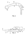
- Figure 3 is a front elevational view of one of the bicycle brake arms of the bicycle brake device that is illustrated in Figures 1 and 2 ;
- Figure 4 is a top plan view of the bicycle brake arm that is illustrated in Figure 3 ;
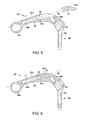
- Figure 5 is a cross-sectional view of the bicycle brake arm that is illustrated in Figures 3 and 4 as seen along the line 5-5, but with the cap or plug (e.g., a solid block) exploded outwardly from the interior cavity of the bicycle brake arm;
- cap or plug e.g., a solid block
- Figure 6 is a cross-sectional view, similar to Figure 5 , of the bicycle brake arm that is illustrated in Figures 3 to 5 , but with the cap or plug (e.g., a solid block) installed in the interior cavity of the bicycle brake arm; and
- the cap or plug e.g., a solid block
- Figure 7 is an enlarged partial cross-sectional view of a modified bicycle brake arm having the cap or plug (e.g., a solid block) bond to the bicycle brake arm by a bonding material (e.g., a metal weld);
- a bonding material e.g., a metal weld
- Figure 8 is an enlarged partial cross-sectional view, similar to Figure 5 , of the modified bicycle brake arm but after surface treating the bonding material to form a seamless connection between the exterior surfaces of the cap and the bicycle brake arm;
- Figure 9 is a cross-sectional view, similar to Figure 5 , of a bicycle brake arm that is illustrated in Figures 3 and 4 , but which is provided with a cap or plug that is formed of a harden putty filler accordance with another illustrated embodiment.
- the bicycle brake device 12 in the illustrated embodiment is a side pull caliper rim brake, and more particularly, a dual-pivot, side pull caliper rim brake.
- the bicycle brake device 12 is attached to a front fork 14 of the bicycle 10 via a mounting bolt 16 in a conventional manner.
- the bicycle brake device 12 is configured and arranged relative to front fork 12 for selectively gripping a bicycle rim 18 of the front wheel to applying a braking force using friction.
- the bicycle brake device 12 can be mounted a rearward portion of the bicycle 10 for selectively gripping a bicycle rim of a rear wheel (not shown).
- the bicycle brake device 12 includes a first brake arm 20, a second brake arm 22 and a mounting arm 24.
- the first brake arm 20 is a generally L-shaped member, while the second brake arm 22 is a Y-shaped member.
- the first brake arm 20, the second brake arm 22 and the mounting arm 24 are rigid members formed of a suitable material such as a metallic material or a fiber reinforced plastic material.
- the first and second brake arms 20 and 22 are pivotally supported relative to each other by the mounting arm 24.
- the second brake arm 20 is pivotally attached to the mounting arm 24 by the mounting bolt 16 that is also used to mount the entire bicycle brake device 12 to the bicycle 10.
- the center axis of the mounting bolt 16 defines a first pivot axis A1 of the bicycle brake device 12.
- the first brake arm 20 is pivotally attached to the mounting arm 24 by a support bolt 26 ( Figure 2 ).
- the center axis of the support bolt 26 defines a second pivot axis A2 of the bicycle brake device 12.
- a dual-pivot arrangement is provided in the bicycle brake device 12 of the illustrated embodiment.
- a spring 28 is provided between the first and second brake arms 20 and 22 in a conventional manner for biasing the first and second brake arms 20 and 22 to their non-braking positions.
- the first brake arm 20 includes a first branch 30 and a second branch 32 extending from the first branch 30.
- the first branch 30 also has an interior cavity 36 that extends along a longitudinal direction L1 of the first branch 30.
- the first branch 30 has a transverse cross-section in which the interior cavity 36 is completely and continuously surrounded by an exterior surface 30a of the first branch 30.
- the first branch 30 further has an opening 38 formed in the exterior surface 30a of the first branch 30. The opening 38 communicates with the interior cavity 36.
- the interior cavity 36 and the opening 38 can be formed in a single drilling operation, or can be formed in two separate drilling operations.
- the interior cavity 36 has a step configuration with a first cylindrical section 36a and a second cylindrical section 36b.
- the first cylindrical section 36a has a diameter that is larger than a diameter of the second cylindrical section 36b.
- the first and second cylindrical sections 36a and 36b are concentrically arranged with respect to the longitudinal direction L1 of the first branch 30.
- the interior cavity 36 also has a third cylindrical section 36c that is angled relative to the first and second cylindrical sections 36a and 36b.
- the third cylindrical section 36c is formed in a drilling operation that occurs after the drilling operation(s) to form the first and second cylindrical sections 36a and 36b.
- the third cylindrical section 36c can be formed prior to the first and second cylindrical sections 36a and 36b, as needed and/or desired.
- the first brake arm 20 is provided with a cap or plug 40 that closes the opening 38 in the exterior surface 30a of the first branch 30 that communicates with the interior cavity 36.
- the cap 40 has an exterior surface 40a that meets with the exterior surface 30a of the first brake arm 20 in a continuously manner.
- the cap 40 is a solid block, which is fitted into the opening 38.
- the cap 40 is a rigid member that is formed of a suitable material such as a metallic material or a fiber reinforced plastic material.
- the cap 40 is bond to the first brake arm 20. For example, if the first brake arm 20 and the cap 40 are both metallic members, then the cap 40 can be bonded to the first brake arm 20 by welding or brazing.
- the cap 40 can be adhesively bonded to the first brake arm 20 with a suitable adhesive. With the cap 40 fitted into the opening 38, the interior cavity 38 is completely and continuously surrounded by the exterior surfaces 30a and 40a. In other words, the interior cavity 38 does not communicate with an area outside of the first brake arm 20 once the cap 40 is fitted into the opening 38.
- the first branch 30 of the first brake arm 20 includes a first cable attachment structure 42 that is located at the free end of the first branch 30.
- the first cable attachment structure 42 has a quick release cable clamp 44 movably mounted in an opening 42a formed in the first branch 30 of the first brake arm 20 in a conventional manner.
- the quick release cable clamp 48 fixes an inner wire cable 46 of a brake cable to the free end of the first branch 30 of the first brake arm 20 for pulling and releasing the inner wire cable 46 of the brake cable relative to an outer casing 48 of the brake cable.
- the second branch 32 of the first brake arm 20 includes a first brake shoe attachment structure 50 that is located at the free end of the second branch 32.
- the second branch 32 of the first brake arm 20 also includes a mounting arm attachment hole 52 for pivotally attaching the mounting arm 24 by the support bolt 26 in a conventional manner.
- the first brake shoe attachment structure 50 has a brake shoe mounting slot 50a that supports a brake shoe assembly 54.
- the brake shoe assembly 54 is a conventional structure that basically includes a shoe holder 56, a brake shoe 58 and a holder mounting bolt 60.
- the brake shoe 58 is detachably mounted to the shoe holder 56.
- the holder mounting bolt 60 is passed through the brake shoe mounting slot 50a, and is threaded into a flat stop nut that is positioned inside the shoe holder 56.
- the shoe holder 56 is a member made from an aluminum alloy.
- the brake shoe 58 is a member made of rubber that extends in the peripheral direction of the rim 18.
- the second brake arm 22 includes a first branch 61, a second branch 62 and a third branch 634.
- the first branch 60 of the second brake arm 22 is pivotally supported on the mounting bolt 16.
- the first branch 61 includes a mounting hole 66 for pivotally attaching the second brake arm 22 to the bicycle fork 14 by the mounting bolt 16 in a conventional manner.
- the second branch 62 of the second brake arm 22 includes a second cable attachment structure 68 that is located at the free end of the second branch 62.
- the second cable attachment structure 68 includes a support opening 68a that supports a cable adjusting bolt unit 70.
- the cable adjusting bolt unit 70 is a conventional structure that contacts the outer casing 48 of the brake cable.
- the third branch 63 of the second brake arm 22 includes a second brake shoe attachment structure 72 that is located at the free end of the third branch 64.
- the second brake shoe attachment structure 72 has a brake shoe mounting slot 72a that supports a brake shoe assembly 74.
- the brake shoe assembly 74 is a conventional structure that basically includes a shoe holder 76, a brake shoe 78 and a holder mounting bolt 80.
- the brake shoe 78 is detachably mounted to the shoe holder 76.
- the holder mounting bolt 80 is passed through the brake shoe mounting slot 72a that is formed in the third branch 64 of the second brake arm 22 includes, and is threaded into a flat stop nut that is positioned inside the shoe holder 76.
- the shoe holder 66 is a member made from an aluminum alloy.
- the brake shoe 68 is a member made of rubber that extends in the peripheral direction of the rim 18.
- the mounting arm 24 includes a first mounting hole 82 at one end and a second mounting hole 84 at the other end.
- the mounting bolt 16 extends through the first mounting hole 82 such that the mounting arm 24 is pivotally supported on the mounting bolt 16.
- the support bolt 26 extends through the second mounting hole 84 such that the mounting arm 24 is pivotally supported on the support bolt 26, which threads into the mounting arm attachment hole 52 of the first brake arm 20.
- the first and second brake arms 20 and 22 are energized toward the brake release side (the direction in which the first and second brake arms 20 and 22 are opened) by the spring 28, which has one end of the spring 28 contacting the second brake arm 22 and the other end of the spring 28 contacting the mounting arm 24.
- the bicycle brake device 12 is installed on the bicycle frame 14 such that the bicycle brake device 12 straddles the rim 18 of the front wheel. More specifically, the bicycle brake device 12 is positioned such that brake shoes 58 and 78 are located proximate opposing sides of the rim 18 of the front wheel. With the bicycle brake device 12 structured in this manner, when the inner wire cable 46 of the brake cable is pulled by a brake lever provided to a handlebar of the bicycle 10, the first and second brake arms 20 and 22 swing toward the rim 18, the brake shoes 58 and 78 are pressed against the rim 18, and a braking force is thereby applied.
- the first and second brake arms 20 and 22 are swung to the other side (the brake release side) by the springs 28, and the braking force is released from the rim 18.
- the first brake arm 20 pivots around different pivot axis A2 and the second brake arm 22 pivots around pivot axis A1 such that a uniform and powerful braking force is obtained at the left and right brake shoes 58 and 78.
- a modified first brake arm 120 is illustrated in accordance with another illustrated embodiment.
- the first brake arm 120 replaces the first brake arm 20 in the bicycle brake device 12 of Figures 1 and 2 .
- the first brake arm 120 includes a first branch 130 and a second branch 132 extending from the first branch 130.
- the first brake arm 120 includes an interior cavity 136 with an opening 138 formed in an exterior surface 130a of the first branch 130.
- the first brake arm 20 is provided with a cap or plug 140 that closes the opening 138 in the exterior surface 130a of the first branch 130 that communicates with the interior cavity 136.
- the first brake arm 120 is identical to the first brake arm 20, except that the opening 138 is configured such that the exterior surface 130a of the first branch 130 meets with the cap 140 to define a groove 131 that surrounds the cap 140 between the exterior surfaces 130a and 140a.
- the groove 131 is continuously provided around the cap 140 for receiving a bonding material 135 (e.g., a metal weld).
- a mechanical surface treatment e.g., a milling process
- connection between the exterior surface 130a of the bicycle brake arm 120 and the exterior surface 140a of the cap 140 is invisible to a naked eye.
- a smooth exterior surface is formed between the exterior surface 130a of the bicycle brake arm 120 and the exterior surface 140a of the cap 140.
- the first brake arm 20 of the bicycle brake device 12 is provided with alternative cap 240.
- the cap 240 is a harden putty filler, which is initial soft and pliable so that the filler material can be filled into the opening 38 and then subsequently harden.
- an epoxy or other filler material is filled into the interior cavity 36 at the opening 38.
- the epoxy or other filler material will then subsequently harden in the interior cavity 36 to seal off the opening 38.
- the cap 240 has an exterior surface 240a that meets with the exterior surface 30a of the first branch 30 to form a seamless connection between the exterior surface 30a of the bicycle brake arm 20 and the exterior surface 240a of the cap 240.
- the filler material forming the cap 240 can be subjected to a mechanical surface treatment (e.g., a milling process) before and/or after the filler material of the cap 240 hardens such that the connection between the exterior surface 30a of the bicycle brake arm 20 and the exterior surface 240a of the cap 240 is invisible to a naked eye.
- a smooth exterior surface is formed between the exterior surface 30a of the bicycle brake arm 20 and the exterior surface 240a of the cap 240.
- first brake arms 20 and 120 With the first brake arms 20 and 120, a weight reduction of approximately ten percent or slightly more can be attained with the first brake arm 20 or 120 being provided with the interior cavity 36 or 136 as compared to a solid brake arm having an identical shape but without the interior cavity 36 or 136.
- the first brake arm 20 is a cold-forged aluminum arm with an aluminum cap
- the first brake arm 20 weights 29 grams as compared to 32 grams for a solid brake arm of the same shape and material.
- the cap out of a lighter weight material further weight reduction may be possible. Also if a cap is not used, then further weight reduction may be possible.
- the bicycle brake arm can also be applied to a brake arm in a cantilever brake or another type of rim brake instead of a caliper brake.
- the size, shape, location or orientation of the various components can be changed as needed and/or desired.
- Components that are shown directly connected or contacting each other can have intermediate structures disposed between them unless otherwise specified.
Landscapes
- Engineering & Computer Science (AREA)
- Mechanical Engineering (AREA)
- Transportation (AREA)
- Braking Arrangements (AREA)
- Transmission Of Braking Force In Braking Systems (AREA)
Abstract
Description
- This invention generally relates to a bicycle brake device. More specifically, the present invention relates to a bicycle brake arm for a bicycle brake device.
- Bicycles are typically provided with at least one brake device for stopping. Currently, a wide variety of bicycle brake devices are available. One of the most popular types of bicycle brake devices is a rim brake. Rim brakes are configured to apply a braking force to the wheel of a bicycle by pinching the rim of the wheel with a pair of brake shoes attached to a pair of brake arms. One well-known example of a rim brake is a caliper brake. Caliper brakes are also available in several configurations. For example, caliper brakes include a side pull type, a center pull type and a dual-pivot, side pull type. One example of a caliper brake is disclosed in
U.S. Patent No. 5,819,880 . - Bicycles should be made as lightweight as possible, and all the parts of a bicycle should therefore be made as light as possible. This is true of bicycle brake devices as well. However, in designing a bicycle part, a balance is typically made between strength and weight reduction. One example of a caliper brake that is provided with a through hole for reduced weight is disclosed in
U.S. Patent Application Publication No. 2008/0202866 . - One aspect is to provide a bicycle brake arm that is relatively lightweight as compared to a conventional bicycle brake arm.
- In view of the state of the known technology, a bicycle brake arm is provided in accordance with a first aspect that basically comprises a first branch and a second branch. The first branch includes a cable attachment structure. The second branch extends from the first branch. The second branch includes a brake shoe attachment structure. At least one of the first and second branches includes an interior cavity. The at least one of the first and second branches has a transverse cross-section in which the interior cavity is completely and continuously surrounded by an exterior surface of the bicycle brake arm.
- In this brake arm of the first aspect, the interior cavity is completely and continuously surrounded by an exterior surface of the bicycle brake arm. Therefore, the brake arm is provided with sufficient strength in a "twist direction" of the brake arm to prevent undesirable twisting of bicycle brake arm as compared to bicycle brake arms having a through opening such as disclosed in
U.S. Patent Application Publication No. 2008/0202866 . - Various objects, features, aspects and advantages of the bicycle brake arm will become apparent to those skilled in the art from the following detailed description, which, taken in conjunction with the annexed drawings, discloses two illustrative embodiments of a bicycle brake arm.
- Referring now to the attached drawings which form a part of this original disclosure:
-
Figure 1 is a front elevational view of a portion of a bicycle that is equipped with a bicycle brake device in accordance with the illustrated embodiments; -
Figure 2 is an exploded view of the bicycle brake device that is illustrated inFigure 1 ; -
Figure 3 is a front elevational view of one of the bicycle brake arms of the bicycle brake device that is illustrated inFigures 1 and2 ; -
Figure 4 is a top plan view of the bicycle brake arm that is illustrated inFigure 3 ; -
Figure 5 is a cross-sectional view of the bicycle brake arm that is illustrated inFigures 3 and 4 as seen along the line 5-5, but with the cap or plug (e.g., a solid block) exploded outwardly from the interior cavity of the bicycle brake arm; -
Figure 6 is a cross-sectional view, similar toFigure 5 , of the bicycle brake arm that is illustrated inFigures 3 to 5 , but with the cap or plug (e.g., a solid block) installed in the interior cavity of the bicycle brake arm; and -
Figure 7 is an enlarged partial cross-sectional view of a modified bicycle brake arm having the cap or plug (e.g., a solid block) bond to the bicycle brake arm by a bonding material (e.g., a metal weld); -
Figure 8 is an enlarged partial cross-sectional view, similar toFigure 5 , of the modified bicycle brake arm but after surface treating the bonding material to form a seamless connection between the exterior surfaces of the cap and the bicycle brake arm; and -
Figure 9 is a cross-sectional view, similar toFigure 5 , of a bicycle brake arm that is illustrated inFigures 3 and 4 , but which is provided with a cap or plug that is formed of a harden putty filler accordance with another illustrated embodiment. - Selected embodiments will now be explained with reference to the drawings. It will be apparent to those skilled in the art from this disclosure that the following descriptions of the embodiments are provided for illustration only and not for the purpose of limiting the invention as defined by the appended claims and their equivalents.
- Referring initially to
Figure 1 , a portion of abicycle 10 is illustrated that is equipped with abicycle brake device 12 in accordance with a first embodiment. Thebicycle brake device 12 in the illustrated embodiment is a side pull caliper rim brake, and more particularly, a dual-pivot, side pull caliper rim brake. In particular, thebicycle brake device 12 is attached to afront fork 14 of thebicycle 10 via amounting bolt 16 in a conventional manner. Thebicycle brake device 12 is configured and arranged relative tofront fork 12 for selectively gripping abicycle rim 18 of the front wheel to applying a braking force using friction. Of course, it will be apparent from this disclosure that thebicycle brake device 12 can be mounted a rearward portion of thebicycle 10 for selectively gripping a bicycle rim of a rear wheel (not shown). - Basically, as seen in
Figures 1 and2 , thebicycle brake device 12 includes afirst brake arm 20, asecond brake arm 22 and amounting arm 24. Thefirst brake arm 20 is a generally L-shaped member, while thesecond brake arm 22 is a Y-shaped member. Thefirst brake arm 20, thesecond brake arm 22 and themounting arm 24 are rigid members formed of a suitable material such as a metallic material or a fiber reinforced plastic material. - The first and
second brake arms mounting arm 24. In particular, thesecond brake arm 20 is pivotally attached to themounting arm 24 by themounting bolt 16 that is also used to mount the entirebicycle brake device 12 to thebicycle 10. The center axis of themounting bolt 16 defines a first pivot axis A1 of thebicycle brake device 12. Thefirst brake arm 20 is pivotally attached to themounting arm 24 by a support bolt 26 (Figure 2 ). The center axis of thesupport bolt 26 defines a second pivot axis A2 of thebicycle brake device 12. Thus, a dual-pivot arrangement is provided in thebicycle brake device 12 of the illustrated embodiment. As seen inFigure 2 , aspring 28 is provided between the first andsecond brake arms second brake arms - In the illustrated embodiment of
Figures 1 and2 , except for the construction of thefirst brake arm 20. Thus, for the sake of brevity, the details of the construction of thebicycle brake device 12 will be omitted. In other words, other than thefirst brake arm 20, the construction of thebicycle brake device 12 will only be discussed briefly herein. - As seen in
Figures 1 to 6 , thefirst brake arm 20 includes afirst branch 30 and asecond branch 32 extending from thefirst branch 30. As seen inFigures 4 to 6 , thefirst branch 30 also has aninterior cavity 36 that extends along a longitudinal direction L1 of thefirst branch 30. As seen inFigure 4 , thefirst branch 30 has a transverse cross-section in which theinterior cavity 36 is completely and continuously surrounded by anexterior surface 30a of thefirst branch 30. As seen inFigures 5 and 6 , thefirst branch 30 further has anopening 38 formed in theexterior surface 30a of thefirst branch 30. The opening 38 communicates with theinterior cavity 36. In the illustrated embodiment, theinterior cavity 36 and theopening 38 can be formed in a single drilling operation, or can be formed in two separate drilling operations. In the illustrated, theinterior cavity 36 has a step configuration with a firstcylindrical section 36a and a secondcylindrical section 36b. The firstcylindrical section 36a has a diameter that is larger than a diameter of the secondcylindrical section 36b. The first and secondcylindrical sections first branch 30. In the illustrated, theinterior cavity 36 also has a thirdcylindrical section 36c that is angled relative to the first and secondcylindrical sections cylindrical section 36c is formed in a drilling operation that occurs after the drilling operation(s) to form the first and secondcylindrical sections cylindrical section 36c can be formed prior to the first and secondcylindrical sections - As seen in
Figures 4 to 6 , thefirst brake arm 20 is provided with a cap or plug 40 that closes theopening 38 in theexterior surface 30a of thefirst branch 30 that communicates with theinterior cavity 36. Thecap 40 has anexterior surface 40a that meets with theexterior surface 30a of thefirst brake arm 20 in a continuously manner. In the illustrated embodiment, thecap 40 is a solid block, which is fitted into theopening 38. Thecap 40 is a rigid member that is formed of a suitable material such as a metallic material or a fiber reinforced plastic material. Thecap 40 is bond to thefirst brake arm 20. For example, if thefirst brake arm 20 and thecap 40 are both metallic members, then thecap 40 can be bonded to thefirst brake arm 20 by welding or brazing. Alternatively, thecap 40 can be adhesively bonded to thefirst brake arm 20 with a suitable adhesive. With thecap 40 fitted into theopening 38, theinterior cavity 38 is completely and continuously surrounded by theexterior surfaces interior cavity 38 does not communicate with an area outside of thefirst brake arm 20 once thecap 40 is fitted into theopening 38. - Referring back to
Figure 1 and2 , thefirst branch 30 of thefirst brake arm 20 includes a firstcable attachment structure 42 that is located at the free end of thefirst branch 30. The firstcable attachment structure 42 has a quickrelease cable clamp 44 movably mounted in anopening 42a formed in thefirst branch 30 of thefirst brake arm 20 in a conventional manner. The quickrelease cable clamp 48 fixes aninner wire cable 46 of a brake cable to the free end of thefirst branch 30 of thefirst brake arm 20 for pulling and releasing theinner wire cable 46 of the brake cable relative to anouter casing 48 of the brake cable. - The
second branch 32 of thefirst brake arm 20 includes a first brakeshoe attachment structure 50 that is located at the free end of thesecond branch 32. Thesecond branch 32 of thefirst brake arm 20 also includes a mountingarm attachment hole 52 for pivotally attaching the mountingarm 24 by thesupport bolt 26 in a conventional manner. The first brakeshoe attachment structure 50 has a brakeshoe mounting slot 50a that supports abrake shoe assembly 54. Thebrake shoe assembly 54 is a conventional structure that basically includes ashoe holder 56, abrake shoe 58 and aholder mounting bolt 60. Thebrake shoe 58 is detachably mounted to theshoe holder 56. Theholder mounting bolt 60 is passed through the brakeshoe mounting slot 50a, and is threaded into a flat stop nut that is positioned inside theshoe holder 56. Theshoe holder 56 is a member made from an aluminum alloy. Thebrake shoe 58 is a member made of rubber that extends in the peripheral direction of therim 18. - Now the
second brake arm 22 will be briefly discussed with reference toFigures 1 and2 . Thesecond brake arm 22 includes afirst branch 61, asecond branch 62 and a third branch 634. Thefirst branch 60 of thesecond brake arm 22 is pivotally supported on the mountingbolt 16. In particular, thefirst branch 61 includes a mountinghole 66 for pivotally attaching thesecond brake arm 22 to thebicycle fork 14 by the mountingbolt 16 in a conventional manner. Thesecond branch 62 of thesecond brake arm 22 includes a secondcable attachment structure 68 that is located at the free end of thesecond branch 62. The secondcable attachment structure 68 includes asupport opening 68a that supports a cableadjusting bolt unit 70. The cableadjusting bolt unit 70 is a conventional structure that contacts theouter casing 48 of the brake cable. Thethird branch 63 of thesecond brake arm 22 includes a second brakeshoe attachment structure 72 that is located at the free end of the third branch 64. The second brakeshoe attachment structure 72 has a brakeshoe mounting slot 72a that supports abrake shoe assembly 74. Thebrake shoe assembly 74 is a conventional structure that basically includes ashoe holder 76, abrake shoe 78 and aholder mounting bolt 80. Thebrake shoe 78 is detachably mounted to theshoe holder 76. Theholder mounting bolt 80 is passed through the brakeshoe mounting slot 72a that is formed in the third branch 64 of thesecond brake arm 22 includes, and is threaded into a flat stop nut that is positioned inside theshoe holder 76. Theshoe holder 66 is a member made from an aluminum alloy. Thebrake shoe 68 is a member made of rubber that extends in the peripheral direction of therim 18. - Now the mounting
arm 24 will be briefly discussed with reference toFigures 1 and2 . The mountingarm 24 includes a first mountinghole 82 at one end and a second mountinghole 84 at the other end. The mountingbolt 16 extends through the first mountinghole 82 such that the mountingarm 24 is pivotally supported on the mountingbolt 16. Thesupport bolt 26 extends through the second mountinghole 84 such that the mountingarm 24 is pivotally supported on thesupport bolt 26, which threads into the mountingarm attachment hole 52 of thefirst brake arm 20. The first andsecond brake arms second brake arms spring 28, which has one end of thespring 28 contacting thesecond brake arm 22 and the other end of thespring 28 contacting the mountingarm 24. - As shown in
Figure 2 , thebicycle brake device 12 is installed on thebicycle frame 14 such that thebicycle brake device 12 straddles therim 18 of the front wheel. More specifically, thebicycle brake device 12 is positioned such thatbrake shoes rim 18 of the front wheel. With thebicycle brake device 12 structured in this manner, when theinner wire cable 46 of the brake cable is pulled by a brake lever provided to a handlebar of thebicycle 10, the first andsecond brake arms rim 18, thebrake shoes rim 18, and a braking force is thereby applied. When the brake lever is returned to its original position, the first andsecond brake arms springs 28, and the braking force is released from therim 18. With thisbicycle brake device 12, thefirst brake arm 20 pivots around different pivot axis A2 and thesecond brake arm 22 pivots around pivot axis A1 such that a uniform and powerful braking force is obtained at the left andright brake shoes - Referring now to
Figures 7 and 8 , a modifiedfirst brake arm 120 is illustrated in accordance with another illustrated embodiment. Thefirst brake arm 120 replaces thefirst brake arm 20 in thebicycle brake device 12 ofFigures 1 and2 . Similar to thefirst brake arm 20, thefirst brake arm 120 includes afirst branch 130 and asecond branch 132 extending from thefirst branch 130. Also thefirst brake arm 120 includes aninterior cavity 136 with anopening 138 formed in anexterior surface 130a of thefirst branch 130. Thefirst brake arm 20 is provided with a cap or plug 140 that closes theopening 138 in theexterior surface 130a of thefirst branch 130 that communicates with theinterior cavity 136. - Here, in this alternate embodiment, the
first brake arm 120 is identical to thefirst brake arm 20, except that theopening 138 is configured such that theexterior surface 130a of thefirst branch 130 meets with thecap 140 to define agroove 131 that surrounds thecap 140 between theexterior surfaces groove 131 is continuously provided around thecap 140 for receiving a bonding material 135 (e.g., a metal weld). As seen inFigure 8 , a mechanical surface treatment (e.g., a milling process) is applied to thebonding material 135 to form a seamless connection between theexterior surface 130a of thebicycle brake arm 120 and anexterior surface 140a of thecap 140. In this way, the connection between theexterior surface 130a of thebicycle brake arm 120 and theexterior surface 140a of thecap 140 is invisible to a naked eye. Thus, a smooth exterior surface is formed between theexterior surface 130a of thebicycle brake arm 120 and theexterior surface 140a of thecap 140. - Referring now to
Figure 9 , thefirst brake arm 20 of thebicycle brake device 12 is provided withalternative cap 240. Thecap 240 is a harden putty filler, which is initial soft and pliable so that the filler material can be filled into theopening 38 and then subsequently harden. In other words, for example, an epoxy or other filler material is filled into theinterior cavity 36 at theopening 38. The epoxy or other filler material will then subsequently harden in theinterior cavity 36 to seal off theopening 38. Thecap 240 has an exterior surface 240a that meets with theexterior surface 30a of thefirst branch 30 to form a seamless connection between theexterior surface 30a of thebicycle brake arm 20 and the exterior surface 240a of thecap 240. The filler material forming thecap 240 can be subjected to a mechanical surface treatment (e.g., a milling process) before and/or after the filler material of thecap 240 hardens such that the connection between theexterior surface 30a of thebicycle brake arm 20 and the exterior surface 240a of thecap 240 is invisible to a naked eye. Thus, a smooth exterior surface is formed between theexterior surface 30a of thebicycle brake arm 20 and the exterior surface 240a of thecap 240. - With the
first brake arms first brake arm interior cavity interior cavity first brake arm 20 is a cold-forged aluminum arm with an aluminum cap, thefirst brake arm 20 weights 29 grams as compared to 32 grams for a solid brake arm of the same shape and material. By making the cap out of a lighter weight material further weight reduction may be possible. Also if a cap is not used, then further weight reduction may be possible. - In understanding the scope of the present invention, the term "comprising" and its derivatives, as used herein, are intended to be open ended terms that specify the presence of the stated features, elements, components, groups, integers, and/or steps, but do not exclude the presence of other unstated features, elements, components, groups, integers and/or steps. The foregoing also applies to words having similar meanings such as the terms, "including", "having" and their derivatives. Also, the terms "part," "section," "portion," "member" or "element" when used in the singular can have the dual meaning of a single part or a plurality of parts unless otherwise specified. As used herein to describe the above embodiment(s), the following directional terms "forward", "rearward", "above", "downward", "vertical", "horizontal", "below" and "transverse" as well as any other similar directional terms refer to those directions of a bicycle equipped with the bicycle brake device on a horizontal surface in the upright position unless otherwise specified. Accordingly, these terms, as utilized to describe the bicycle brake device should be interpreted relative to a bicycle equipped with the bicycle brake device as used in the normal riding position unless otherwise specified. Finally, terms of degree such as "substantially", "about" and "approximately" as used herein mean a reasonable amount of deviation of the modified term such that the end result is not significantly changed.
- While only selected embodiments have been chosen to illustrate the present invention, it will be apparent to those skilled in the art from this disclosure that various changes and modifications can be made herein without departing from the scope of the invention as defined in the appended claims. For example, the bicycle brake arm can also be applied to a brake arm in a cantilever brake or another type of rim brake instead of a caliper brake. For example, the size, shape, location or orientation of the various components can be changed as needed and/or desired. Components that are shown directly connected or contacting each other can have intermediate structures disposed between them unless otherwise specified. Thus, the foregoing descriptions of the embodiments according to the present invention are provided for illustration only, and not for the purpose of limiting the invention as defined by the appended claims and their equivalents.
Claims (20)
- A bicycle brake arm having
a transverse cross-section in which an interior cavity is completely and continuously surrounded by an exterior surface. - A bicycle brake arm comprising:a first branch including a cable attachment structure; anda second branch extending from the first branch, the second branch including a brake shoe attachment structure,at least one of the first and second branches including an interior cavity, the at least one of the first and second branches having a transverse cross-section in which the interior cavity is completely and continuously surrounded by an exterior surface of the bicycle brake arm.
- The bicycle brake arm according to claim 2, wherein
the interior cavity has an opening formed in the exterior surface of the bicycle brake arm. - The bicycle brake arm according to claim 3, further comprising
a cap that closes the opening in the exterior surface that communicates with the interior cavity. - The bicycle brake arm according to claim 4, wherein
the cap has an exterior surface that seamlessly meets with the exterior surface of the bicycle brake arm in a continuously manner. - The bicycle brake arm according to claim 5, wherein
the cap is a block which is fitted into the opening. - The bicycle brake arm according to claim 5, wherein
the cap is a harden putty filler which is filled in the opening. - The bicycle brake arm according to claim 2, wherein
the interior cavity has a cylindrically shape which extends along a longitudinal direction of the at least one of the first and second branches of the bicycle brake arm. - The bicycle brake arm according to claim 8, wherein
the interior cavity has an opening formed in the exterior surface of the bicycle brake arm. - The bicycle brake arm according to claim 9, further comprising
a cap that closes the opening in the exterior surface that communicates with the interior cavity. - The bicycle brake arm according to claim 10, wherein
the cap has an exterior surface that seamlessly meets with the exterior surface of the bicycle brake arm in a continuously manner. - The bicycle brake arm according to claim 10, wherein
the cap is a block which is fitted into the opening. - The bicycle brake arm according to claim 10, wherein
the cap is a harden putty filler which is filled in the opening. - A bicycle brake device comprising:a first brake arm including a first brake shoe attachment structure, and a first cable attachment structure, the first brake arm including at least one interior cavity; anda second brake arm including a second brake shoe attachment structure, and a first cable attachment structure, the first and second brake arm being pivotally supported relative to each other;the first brake arm having a transverse cross-section in which the interior cavity is completely and continuously surrounded by an exterior surface.
- The bicycle brake device according to claim 14, wherein
the first brake arm includes a first branch having a first cable attachment structure, and a second branch having a first brake shoe attachment structure, at least one of the first and second branches including the interior cavity. - The bicycle brake arm according to claim 14, wherein
the interior cavity has an opening formed in the exterior surface of the bicycle brake arm. - The bicycle brake arm according to claim 16, further comprising
a cap that closes the opening in the exterior surface that communicates with the interior cavity. - The bicycle brake arm according to claim 16, wherein
the cap is a block which is fitted into the opening. - The bicycle brake arm according to claim 16, wherein
the cap is a harden putty filler which is filled in the opening. - The bicycle brake arm according to claim 14, wherein
the interior cavity has a cylindrically shape which extends along a longitudinal direction of the at least one of the first brake arm.
Applications Claiming Priority (1)
| Application Number | Priority Date | Filing Date | Title |
|---|---|---|---|
| US13/184,671 US8813920B2 (en) | 2011-07-18 | 2011-07-18 | Bicycle brake arm |
Publications (3)
| Publication Number | Publication Date |
|---|---|
| EP2548793A2 true EP2548793A2 (en) | 2013-01-23 |
| EP2548793A3 EP2548793A3 (en) | 2014-05-28 |
| EP2548793B1 EP2548793B1 (en) | 2015-10-14 |
Family
ID=46384190
Family Applications (1)
| Application Number | Title | Priority Date | Filing Date |
|---|---|---|---|
| EP12172903.2A Not-in-force EP2548793B1 (en) | 2011-07-18 | 2012-06-21 | Bicycle brake arm |
Country Status (4)
| Country | Link |
|---|---|
| US (1) | US8813920B2 (en) |
| EP (1) | EP2548793B1 (en) |
| CN (1) | CN102887196B (en) |
| TW (1) | TWI526359B (en) |
Cited By (1)
| Publication number | Priority date | Publication date | Assignee | Title |
|---|---|---|---|---|
| US9821880B2 (en) | 2015-08-07 | 2017-11-21 | Shimano Inc. | Bicycle rim brake |
Families Citing this family (2)
| Publication number | Priority date | Publication date | Assignee | Title |
|---|---|---|---|---|
| CN104315048A (en) * | 2014-10-22 | 2015-01-28 | 中国重汽集团济南动力有限公司 | Novel manual adjustment cap |
| USD908564S1 (en) * | 2019-07-29 | 2021-01-26 | Pacific Cycle, Llc | Brake caliper lever assembly |
Citations (2)
| Publication number | Priority date | Publication date | Assignee | Title |
|---|---|---|---|---|
| US5819880A (en) | 1996-04-02 | 1998-10-13 | Shimano, Inc. | Bicycle brake shoe holder |
| US20080202866A1 (en) | 2005-12-02 | 2008-08-28 | Campagnolo S.R.L. | Bicycle brake |
Family Cites Families (15)
| Publication number | Priority date | Publication date | Assignee | Title |
|---|---|---|---|---|
| DE2327420A1 (en) * | 1973-05-29 | 1974-12-19 | Altenburger Kg | RIM BRAKE |
| US4388848A (en) * | 1981-05-04 | 1983-06-21 | Q Corporation | Cutter ring and method of making same |
| DE3631299A1 (en) * | 1986-09-13 | 1988-03-24 | Magenwirth Gmbh Co Gustav | HYDRAULIC RIM BRAKE FOR BICYCLES |
| US5415423A (en) * | 1989-04-07 | 1995-05-16 | Softride, Inc. | Modular composite bicycle frame |
| CN2147175Y (en) * | 1993-01-09 | 1993-11-24 | 律宝实业有限公司 | Improved bicycle brakes |
| US5417311A (en) * | 1993-10-12 | 1995-05-23 | Musco, Iii; Nicholas | Bicycle brake assembly |
| US5503252A (en) * | 1995-05-11 | 1996-04-02 | Gelbein; Mark | Bicycle brake assembly |
| FR2780021B1 (en) * | 1998-06-17 | 2000-09-22 | Mavic Sa | SKATE TYPE BICYCLE BRAKE |
| US5960913A (en) * | 1999-02-08 | 1999-10-05 | Kuo; Yung-Pin | Device for adjusting the brake pad relative to the wheel rim of a bicycle |
| US6349799B1 (en) * | 2000-03-15 | 2002-02-26 | Shimano Inc. | Bicycle brake device |
| DE202004013602U1 (en) * | 2004-08-30 | 2006-01-05 | Canyon Bicycles Gmbh | calipers |
| US8096392B2 (en) * | 2007-09-26 | 2012-01-17 | Craig Hawley Edwards | Light weight bicycle brake assembly |
| US7802660B2 (en) * | 2008-02-01 | 2010-09-28 | Tektro Technology Corporation | Quick-release device of a bicycle brake cable |
| US8448752B2 (en) * | 2009-12-21 | 2013-05-28 | Ashima Ltd. | Hydraulic brake device |
| TWM384824U (en) | 2010-02-11 | 2010-07-21 | Sheng-Yao Yang | Cellular type brake clip device |
-
2011
- 2011-07-18 US US13/184,671 patent/US8813920B2/en not_active Expired - Fee Related
-
2012
- 2012-02-06 TW TW101103798A patent/TWI526359B/en not_active IP Right Cessation
- 2012-06-19 CN CN201210210024.0A patent/CN102887196B/en not_active Expired - Fee Related
- 2012-06-21 EP EP12172903.2A patent/EP2548793B1/en not_active Not-in-force
Patent Citations (2)
| Publication number | Priority date | Publication date | Assignee | Title |
|---|---|---|---|---|
| US5819880A (en) | 1996-04-02 | 1998-10-13 | Shimano, Inc. | Bicycle brake shoe holder |
| US20080202866A1 (en) | 2005-12-02 | 2008-08-28 | Campagnolo S.R.L. | Bicycle brake |
Cited By (2)
| Publication number | Priority date | Publication date | Assignee | Title |
|---|---|---|---|---|
| US9821880B2 (en) | 2015-08-07 | 2017-11-21 | Shimano Inc. | Bicycle rim brake |
| DE102016008808B4 (en) * | 2015-08-07 | 2025-10-30 | Shimano Inc. | bicycle rim brake |
Also Published As
| Publication number | Publication date |
|---|---|
| US20130020152A1 (en) | 2013-01-24 |
| TWI526359B (en) | 2016-03-21 |
| TW201305006A (en) | 2013-02-01 |
| CN102887196A (en) | 2013-01-23 |
| US8813920B2 (en) | 2014-08-26 |
| CN102887196B (en) | 2015-10-28 |
| EP2548793A3 (en) | 2014-05-28 |
| EP2548793B1 (en) | 2015-10-14 |
Similar Documents
| Publication | Publication Date | Title |
|---|---|---|
| US9120522B1 (en) | Bicycle hydraulic operating device and bicycle hydraulic device assembly | |
| US9174697B2 (en) | Bicycle operating device | |
| CN104747624B (en) | Disc type braking tong | |
| US9321501B1 (en) | Bicycle control device | |
| US9896150B2 (en) | Bicycle operating device | |
| EP2574535B1 (en) | Bicycle control device | |
| US10183724B2 (en) | Bicycle hydraulic operating system | |
| TW201514047A (en) | Bicycle hydraulic operating device | |
| US8413769B2 (en) | Bicycle brake system using cam mechanism | |
| EP2548793B1 (en) | Bicycle brake arm | |
| US8485320B2 (en) | Bicycle brake | |
| US6186529B1 (en) | Bicycle brake mounting structure | |
| US20160031522A1 (en) | Bicycle rim brake | |
| US7802661B2 (en) | Brake device for motorcycle | |
| US20150135881A1 (en) | Integrated drive for bicycle handlebars | |
| EP2444310B1 (en) | Bicycle brake system using cam mechanism | |
| US8636294B2 (en) | Passage system for transmission elements of bicycle components | |
| TW201400354A (en) | Bicycle brake assembly | |
| CN101076473B (en) | Bicycle brake | |
| JP3543943B2 (en) | Bicycle braking force adjuster | |
| US10766301B2 (en) | Rear wheel fixing mechanism for a bicycle | |
| US10384744B2 (en) | Bicycle operating device | |
| CZ294074B6 (en) | Brake set for bicycles | |
| US6607056B2 (en) | Brake apparatus for a bicycle and bicycle comprising this apparatus | |
| US8757561B2 (en) | Bicycle brake cable hanger |
Legal Events
| Date | Code | Title | Description |
|---|---|---|---|
| PUAI | Public reference made under article 153(3) epc to a published international application that has entered the european phase |
Free format text: ORIGINAL CODE: 0009012 |
|
| AK | Designated contracting states |
Kind code of ref document: A2 Designated state(s): AL AT BE BG CH CY CZ DE DK EE ES FI FR GB GR HR HU IE IS IT LI LT LU LV MC MK MT NL NO PL PT RO RS SE SI SK SM TR |
|
| AX | Request for extension of the european patent |
Extension state: BA ME |
|
| PUAL | Search report despatched |
Free format text: ORIGINAL CODE: 0009013 |
|
| AK | Designated contracting states |
Kind code of ref document: A3 Designated state(s): AL AT BE BG CH CY CZ DE DK EE ES FI FR GB GR HR HU IE IS IT LI LT LU LV MC MK MT NL NO PL PT RO RS SE SI SK SM TR |
|
| AX | Request for extension of the european patent |
Extension state: BA ME |
|
| RIC1 | Information provided on ipc code assigned before grant |
Ipc: B62L 1/16 20060101AFI20140424BHEP |
|
| 17P | Request for examination filed |
Effective date: 20141124 |
|
| RBV | Designated contracting states (corrected) |
Designated state(s): AL AT BE BG CH CY CZ DE DK EE ES FI FR GB GR HR HU IE IS IT LI LT LU LV MC MK MT NL NO PL PT RO RS SE SI SK SM TR |
|
| GRAP | Despatch of communication of intention to grant a patent |
Free format text: ORIGINAL CODE: EPIDOSNIGR1 |
|
| INTG | Intention to grant announced |
Effective date: 20150603 |
|
| GRAS | Grant fee paid |
Free format text: ORIGINAL CODE: EPIDOSNIGR3 |
|
| GRAA | (expected) grant |
Free format text: ORIGINAL CODE: 0009210 |
|
| AK | Designated contracting states |
Kind code of ref document: B1 Designated state(s): AL AT BE BG CH CY CZ DE DK EE ES FI FR GB GR HR HU IE IS IT LI LT LU LV MC MK MT NL NO PL PT RO RS SE SI SK SM TR |
|
| REG | Reference to a national code |
Ref country code: GB Ref legal event code: FG4D |
|
| REG | Reference to a national code |
Ref country code: AT Ref legal event code: REF Ref document number: 754891 Country of ref document: AT Kind code of ref document: T Effective date: 20151015 Ref country code: CH Ref legal event code: EP |
|
| REG | Reference to a national code |
Ref country code: IE Ref legal event code: FG4D |
|
| REG | Reference to a national code |
Ref country code: DE Ref legal event code: R096 Ref document number: 602012011473 Country of ref document: DE |
|
| REG | Reference to a national code |
Ref country code: NL Ref legal event code: MP Effective date: 20151014 |
|
| REG | Reference to a national code |
Ref country code: LT Ref legal event code: MG4D |
|
| REG | Reference to a national code |
Ref country code: AT Ref legal event code: MK05 Ref document number: 754891 Country of ref document: AT Kind code of ref document: T Effective date: 20151014 |
|
| PG25 | Lapsed in a contracting state [announced via postgrant information from national office to epo] |
Ref country code: HR Free format text: LAPSE BECAUSE OF FAILURE TO SUBMIT A TRANSLATION OF THE DESCRIPTION OR TO PAY THE FEE WITHIN THE PRESCRIBED TIME-LIMIT Effective date: 20151014 Ref country code: NL Free format text: LAPSE BECAUSE OF FAILURE TO SUBMIT A TRANSLATION OF THE DESCRIPTION OR TO PAY THE FEE WITHIN THE PRESCRIBED TIME-LIMIT Effective date: 20151014 Ref country code: NO Free format text: LAPSE BECAUSE OF FAILURE TO SUBMIT A TRANSLATION OF THE DESCRIPTION OR TO PAY THE FEE WITHIN THE PRESCRIBED TIME-LIMIT Effective date: 20160114 Ref country code: ES Free format text: LAPSE BECAUSE OF FAILURE TO SUBMIT A TRANSLATION OF THE DESCRIPTION OR TO PAY THE FEE WITHIN THE PRESCRIBED TIME-LIMIT Effective date: 20151014 Ref country code: LT Free format text: LAPSE BECAUSE OF FAILURE TO SUBMIT A TRANSLATION OF THE DESCRIPTION OR TO PAY THE FEE WITHIN THE PRESCRIBED TIME-LIMIT Effective date: 20151014 Ref country code: IS Free format text: LAPSE BECAUSE OF FAILURE TO SUBMIT A TRANSLATION OF THE DESCRIPTION OR TO PAY THE FEE WITHIN THE PRESCRIBED TIME-LIMIT Effective date: 20160214 |
|
| PG25 | Lapsed in a contracting state [announced via postgrant information from national office to epo] |
Ref country code: PT Free format text: LAPSE BECAUSE OF FAILURE TO SUBMIT A TRANSLATION OF THE DESCRIPTION OR TO PAY THE FEE WITHIN THE PRESCRIBED TIME-LIMIT Effective date: 20160215 Ref country code: GR Free format text: LAPSE BECAUSE OF FAILURE TO SUBMIT A TRANSLATION OF THE DESCRIPTION OR TO PAY THE FEE WITHIN THE PRESCRIBED TIME-LIMIT Effective date: 20160115 Ref country code: SE Free format text: LAPSE BECAUSE OF FAILURE TO SUBMIT A TRANSLATION OF THE DESCRIPTION OR TO PAY THE FEE WITHIN THE PRESCRIBED TIME-LIMIT Effective date: 20151014 Ref country code: PL Free format text: LAPSE BECAUSE OF FAILURE TO SUBMIT A TRANSLATION OF THE DESCRIPTION OR TO PAY THE FEE WITHIN THE PRESCRIBED TIME-LIMIT Effective date: 20151014 Ref country code: LV Free format text: LAPSE BECAUSE OF FAILURE TO SUBMIT A TRANSLATION OF THE DESCRIPTION OR TO PAY THE FEE WITHIN THE PRESCRIBED TIME-LIMIT Effective date: 20151014 Ref country code: FI Free format text: LAPSE BECAUSE OF FAILURE TO SUBMIT A TRANSLATION OF THE DESCRIPTION OR TO PAY THE FEE WITHIN THE PRESCRIBED TIME-LIMIT Effective date: 20151014 Ref country code: AT Free format text: LAPSE BECAUSE OF FAILURE TO SUBMIT A TRANSLATION OF THE DESCRIPTION OR TO PAY THE FEE WITHIN THE PRESCRIBED TIME-LIMIT Effective date: 20151014 Ref country code: RS Free format text: LAPSE BECAUSE OF FAILURE TO SUBMIT A TRANSLATION OF THE DESCRIPTION OR TO PAY THE FEE WITHIN THE PRESCRIBED TIME-LIMIT Effective date: 20151014 |
|
| REG | Reference to a national code |
Ref country code: DE Ref legal event code: R097 Ref document number: 602012011473 Country of ref document: DE |
|
| PG25 | Lapsed in a contracting state [announced via postgrant information from national office to epo] |
Ref country code: CZ Free format text: LAPSE BECAUSE OF FAILURE TO SUBMIT A TRANSLATION OF THE DESCRIPTION OR TO PAY THE FEE WITHIN THE PRESCRIBED TIME-LIMIT Effective date: 20151014 |
|
| PLBE | No opposition filed within time limit |
Free format text: ORIGINAL CODE: 0009261 |
|
| STAA | Information on the status of an ep patent application or granted ep patent |
Free format text: STATUS: NO OPPOSITION FILED WITHIN TIME LIMIT |
|
| PG25 | Lapsed in a contracting state [announced via postgrant information from national office to epo] |
Ref country code: RO Free format text: LAPSE BECAUSE OF FAILURE TO SUBMIT A TRANSLATION OF THE DESCRIPTION OR TO PAY THE FEE WITHIN THE PRESCRIBED TIME-LIMIT Effective date: 20151014 Ref country code: DK Free format text: LAPSE BECAUSE OF FAILURE TO SUBMIT A TRANSLATION OF THE DESCRIPTION OR TO PAY THE FEE WITHIN THE PRESCRIBED TIME-LIMIT Effective date: 20151014 Ref country code: EE Free format text: LAPSE BECAUSE OF FAILURE TO SUBMIT A TRANSLATION OF THE DESCRIPTION OR TO PAY THE FEE WITHIN THE PRESCRIBED TIME-LIMIT Effective date: 20151014 Ref country code: SK Free format text: LAPSE BECAUSE OF FAILURE TO SUBMIT A TRANSLATION OF THE DESCRIPTION OR TO PAY THE FEE WITHIN THE PRESCRIBED TIME-LIMIT Effective date: 20151014 Ref country code: SM Free format text: LAPSE BECAUSE OF FAILURE TO SUBMIT A TRANSLATION OF THE DESCRIPTION OR TO PAY THE FEE WITHIN THE PRESCRIBED TIME-LIMIT Effective date: 20151014 |
|
| 26N | No opposition filed |
Effective date: 20160715 |
|
| PG25 | Lapsed in a contracting state [announced via postgrant information from national office to epo] |
Ref country code: SI Free format text: LAPSE BECAUSE OF FAILURE TO SUBMIT A TRANSLATION OF THE DESCRIPTION OR TO PAY THE FEE WITHIN THE PRESCRIBED TIME-LIMIT Effective date: 20151014 |
|
| PG25 | Lapsed in a contracting state [announced via postgrant information from national office to epo] |
Ref country code: BE Free format text: LAPSE BECAUSE OF FAILURE TO SUBMIT A TRANSLATION OF THE DESCRIPTION OR TO PAY THE FEE WITHIN THE PRESCRIBED TIME-LIMIT Effective date: 20151014 |
|
| PG25 | Lapsed in a contracting state [announced via postgrant information from national office to epo] |
Ref country code: MC Free format text: LAPSE BECAUSE OF FAILURE TO SUBMIT A TRANSLATION OF THE DESCRIPTION OR TO PAY THE FEE WITHIN THE PRESCRIBED TIME-LIMIT Effective date: 20151014 |
|
| REG | Reference to a national code |
Ref country code: CH Ref legal event code: PL |
|
| GBPC | Gb: european patent ceased through non-payment of renewal fee |
Effective date: 20160621 |
|
| REG | Reference to a national code |
Ref country code: IE Ref legal event code: MM4A |
|
| REG | Reference to a national code |
Ref country code: FR Ref legal event code: ST Effective date: 20170228 |
|
| PG25 | Lapsed in a contracting state [announced via postgrant information from national office to epo] |
Ref country code: FR Free format text: LAPSE BECAUSE OF NON-PAYMENT OF DUE FEES Effective date: 20160630 Ref country code: LI Free format text: LAPSE BECAUSE OF NON-PAYMENT OF DUE FEES Effective date: 20160630 Ref country code: CH Free format text: LAPSE BECAUSE OF NON-PAYMENT OF DUE FEES Effective date: 20160630 |
|
| PG25 | Lapsed in a contracting state [announced via postgrant information from national office to epo] |
Ref country code: GB Free format text: LAPSE BECAUSE OF NON-PAYMENT OF DUE FEES Effective date: 20160621 Ref country code: IE Free format text: LAPSE BECAUSE OF NON-PAYMENT OF DUE FEES Effective date: 20160621 |
|
| PGFP | Annual fee paid to national office [announced via postgrant information from national office to epo] |
Ref country code: IT Payment date: 20170619 Year of fee payment: 6 |
|
| PG25 | Lapsed in a contracting state [announced via postgrant information from national office to epo] |
Ref country code: HU Free format text: LAPSE BECAUSE OF FAILURE TO SUBMIT A TRANSLATION OF THE DESCRIPTION OR TO PAY THE FEE WITHIN THE PRESCRIBED TIME-LIMIT; INVALID AB INITIO Effective date: 20120621 Ref country code: CY Free format text: LAPSE BECAUSE OF FAILURE TO SUBMIT A TRANSLATION OF THE DESCRIPTION OR TO PAY THE FEE WITHIN THE PRESCRIBED TIME-LIMIT Effective date: 20151014 |
|
| PG25 | Lapsed in a contracting state [announced via postgrant information from national office to epo] |
Ref country code: TR Free format text: LAPSE BECAUSE OF FAILURE TO SUBMIT A TRANSLATION OF THE DESCRIPTION OR TO PAY THE FEE WITHIN THE PRESCRIBED TIME-LIMIT Effective date: 20151014 Ref country code: MT Free format text: LAPSE BECAUSE OF NON-PAYMENT OF DUE FEES Effective date: 20160630 Ref country code: LU Free format text: LAPSE BECAUSE OF NON-PAYMENT OF DUE FEES Effective date: 20160621 Ref country code: MK Free format text: LAPSE BECAUSE OF FAILURE TO SUBMIT A TRANSLATION OF THE DESCRIPTION OR TO PAY THE FEE WITHIN THE PRESCRIBED TIME-LIMIT Effective date: 20151014 |
|
| PG25 | Lapsed in a contracting state [announced via postgrant information from national office to epo] |
Ref country code: BG Free format text: LAPSE BECAUSE OF FAILURE TO SUBMIT A TRANSLATION OF THE DESCRIPTION OR TO PAY THE FEE WITHIN THE PRESCRIBED TIME-LIMIT Effective date: 20151014 |
|
| PG25 | Lapsed in a contracting state [announced via postgrant information from national office to epo] |
Ref country code: AL Free format text: LAPSE BECAUSE OF FAILURE TO SUBMIT A TRANSLATION OF THE DESCRIPTION OR TO PAY THE FEE WITHIN THE PRESCRIBED TIME-LIMIT Effective date: 20151014 |
|
| PG25 | Lapsed in a contracting state [announced via postgrant information from national office to epo] |
Ref country code: IT Free format text: LAPSE BECAUSE OF NON-PAYMENT OF DUE FEES Effective date: 20180621 |
|
| PGFP | Annual fee paid to national office [announced via postgrant information from national office to epo] |
Ref country code: DE Payment date: 20200609 Year of fee payment: 9 |
|
| REG | Reference to a national code |
Ref country code: DE Ref legal event code: R119 Ref document number: 602012011473 Country of ref document: DE |
|
| PG25 | Lapsed in a contracting state [announced via postgrant information from national office to epo] |
Ref country code: DE Free format text: LAPSE BECAUSE OF NON-PAYMENT OF DUE FEES Effective date: 20220101 |