EP2548775A1 - Fahrzeug mit einem Hochdruckspeicher - Google Patents
Fahrzeug mit einem Hochdruckspeicher Download PDFInfo
- Publication number
- EP2548775A1 EP2548775A1 EP12001369A EP12001369A EP2548775A1 EP 2548775 A1 EP2548775 A1 EP 2548775A1 EP 12001369 A EP12001369 A EP 12001369A EP 12001369 A EP12001369 A EP 12001369A EP 2548775 A1 EP2548775 A1 EP 2548775A1
- Authority
- EP
- European Patent Office
- Prior art keywords
- volume flow
- pressure accumulator
- hydraulic
- hydraulic motor
- vehicle
- Prior art date
- Legal status (The legal status is an assumption and is not a legal conclusion. Google has not performed a legal analysis and makes no representation as to the accuracy of the status listed.)
- Granted
Links
Images
Classifications
-
- B—PERFORMING OPERATIONS; TRANSPORTING
- B60—VEHICLES IN GENERAL
- B60K—ARRANGEMENT OR MOUNTING OF PROPULSION UNITS OR OF TRANSMISSIONS IN VEHICLES; ARRANGEMENT OR MOUNTING OF PLURAL DIVERSE PRIME-MOVERS IN VEHICLES; AUXILIARY DRIVES FOR VEHICLES; INSTRUMENTATION OR DASHBOARDS FOR VEHICLES; ARRANGEMENTS IN CONNECTION WITH COOLING, AIR INTAKE, GAS EXHAUST OR FUEL SUPPLY OF PROPULSION UNITS IN VEHICLES
- B60K6/00—Arrangement or mounting of plural diverse prime-movers for mutual or common propulsion, e.g. hybrid propulsion systems comprising electric motors and internal combustion engines
- B60K6/08—Prime-movers comprising combustion engines and mechanical or fluid energy storing means
- B60K6/12—Prime-movers comprising combustion engines and mechanical or fluid energy storing means by means of a chargeable fluidic accumulator
-
- B—PERFORMING OPERATIONS; TRANSPORTING
- B60—VEHICLES IN GENERAL
- B60T—VEHICLE BRAKE CONTROL SYSTEMS OR PARTS THEREOF; BRAKE CONTROL SYSTEMS OR PARTS THEREOF, IN GENERAL; ARRANGEMENT OF BRAKING ELEMENTS ON VEHICLES IN GENERAL; PORTABLE DEVICES FOR PREVENTING UNWANTED MOVEMENT OF VEHICLES; VEHICLE MODIFICATIONS TO FACILITATE COOLING OF BRAKES
- B60T1/00—Arrangements of braking elements, i.e. of those parts where braking effect occurs specially for vehicles
- B60T1/02—Arrangements of braking elements, i.e. of those parts where braking effect occurs specially for vehicles acting by retarding wheels
- B60T1/10—Arrangements of braking elements, i.e. of those parts where braking effect occurs specially for vehicles acting by retarding wheels by utilising wheel movement for accumulating energy, e.g. driving air compressors
-
- B—PERFORMING OPERATIONS; TRANSPORTING
- B60—VEHICLES IN GENERAL
- B60T—VEHICLE BRAKE CONTROL SYSTEMS OR PARTS THEREOF; BRAKE CONTROL SYSTEMS OR PARTS THEREOF, IN GENERAL; ARRANGEMENT OF BRAKING ELEMENTS ON VEHICLES IN GENERAL; PORTABLE DEVICES FOR PREVENTING UNWANTED MOVEMENT OF VEHICLES; VEHICLE MODIFICATIONS TO FACILITATE COOLING OF BRAKES
- B60T10/00—Control or regulation for continuous braking making use of fluid or powdered medium, e.g. for use when descending a long slope
- B60T10/04—Control or regulation for continuous braking making use of fluid or powdered medium, e.g. for use when descending a long slope with hydrostatic brake
-
- Y—GENERAL TAGGING OF NEW TECHNOLOGICAL DEVELOPMENTS; GENERAL TAGGING OF CROSS-SECTIONAL TECHNOLOGIES SPANNING OVER SEVERAL SECTIONS OF THE IPC; TECHNICAL SUBJECTS COVERED BY FORMER USPC CROSS-REFERENCE ART COLLECTIONS [XRACs] AND DIGESTS
- Y02—TECHNOLOGIES OR APPLICATIONS FOR MITIGATION OR ADAPTATION AGAINST CLIMATE CHANGE
- Y02T—CLIMATE CHANGE MITIGATION TECHNOLOGIES RELATED TO TRANSPORTATION
- Y02T10/00—Road transport of goods or passengers
- Y02T10/60—Other road transportation technologies with climate change mitigation effect
- Y02T10/62—Hybrid vehicles
Definitions
- the invention relates to a vehicle with a high-pressure accumulator according to the preamble of patent claim 1.
- the invention has for its object to form a vehicle with a high-pressure accumulator for storing braking energy so that a retarder braking torque can be provided by means of a hydraulic motor provided even with long-lasting braking.
- At least one hydraulic motor is provided which, in overrun mode, selectively pumps a controllable hydraulic volume flow via a control module into the high-pressure reservoir or into a reservoir.
- the volume flow is controllable by means of a controllable throttle valve, so that in overrun operation, the hydraulic motor generates a retarder braking torque, which allows a targeted braking of the drive wheels and thus of the vehicle.
- the hydraulic motor In overrun mode, the hydraulic motor has the function of a hydraulic pump and initially delivers a throttled volume flow into the high-pressure accumulator until it has reached a maximum pressure limit. From reaching the pressure limit of the hydraulic motor promotes the flow through the control module in a reservoir, wherein the desired retarder braking torque is further provided by a corresponding throttling of the flow rate.
- A for example, arranged in the drive train of a drive motor hydraulic motor can be acted upon by the high-pressure accumulator with a flow to support the drive motor of the vehicle during acceleration.
- the stored braking energy can be used during propulsion to generate a boost function (gain function).
- the throttle valve used in the control module is formed according to an embodiment of the invention as a proportional valve with which a variable control of the flow rate is possible.
- a proportional valve By means of the proportional valve, a continuous control of the retarder braking torque can be realized.
- the volume flow passed from the control module to the reservoir in the overrun mode when the high-pressure accumulator is filled to the maximum is preferably passed through a cooling system in order to cool the hydraulic fluid before it reaches the reservoir.
- a cooling system for this purpose, the cooling system of a drive motor can be used, wherein the drive motor may be a conventional diesel engine or generally an internal combustion engine.
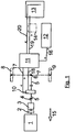
- FIG. 1 shows the schematic representation of the traction drive of a vehicle with a traction motor 1, which drives a propeller shaft 4 via a clutch 2 and a manual transmission 3.
- the propeller shaft 4 is part of a propeller shaft 5, the rear axle 7 and thus the drive wheels 8, 9 drives via a central axle drive 6.
- the drive motor 1 can be designed as an internal combustion engine.
- a hydraulic motor 10 is arranged, the drive shaft is also part of the propeller shaft 5.
- the hydraulic system provided for operating the hydraulic motor 10 is shown enlarged and consists essentially of a control module 11 a high-pressure accumulator 12 and a reservoir 13. With dotted line a cooling system 14 is indicated.
- the control module 11 switches the hydraulic line 16 leading from the high-pressure accumulator 12 to the control module 11 onto the supply line 17 leading to the hydraulic motor 10. At the same time, the volume flow recirculated from the hydraulic motor 10 passes via a return line 18 and via the control module 11 to a return line 19 leading to the reservoir 13. If the maximum possible volume flow from the high-pressure accumulator 12 is used for driving the hydraulic motor 10 in this drive support, this results in the maximum increase in the drive torque in the drive shaft 5.
- control module can also make a limited or throttled forwarding of the volume flow from the high-pressure accumulator 12 to the hydraulic motor 10, if only a reduced drive assistance is to take place.
- a drive assist is, of course, only possible by means of the hydraulic motor 10, as in the high pressure accumulator 12 sufficient overpressure to provide a corresponding volume flow is available.
- the hydraulic motor 10 operates as a hydraulic pump, which is driven by the propeller shaft 5.
- a volume flow is fed via the hydraulic control line 16 into the high-pressure accumulator 12 via the control module 11 until a predetermined maximum pressure value has been reached there.
- the control module switches in overrun mode the volume flow delivered by the hydraulic motor 10 to the leading to the reservoir 13 return line 19 to.
- the cooling system 14 can make a cooling of the flow before it in the Reservoir 13 passes.
- a throttle valve or a proportional valve can be used for throttling the volume flow in overrun mode, the throttle function of which can be controlled as a function of driving parameters.
- a desired retarder braking torque can be generated in the overrun mode by means of the hydraulic motor 10 on the articulated shaft rod 5.
- the hydraulic motor 10 on the articulated shaft rod 5.
- a desired increase in the drive torque via the hydraulic motor 10 are transmitted to the propeller shaft 5.
- a retarder braking torque in the manner described with reference to the exemplary embodiment is also suitable for vehicles which have hydraulic motors assigned to the individual drive wheels and which are driven by means of a volumetric flow delivered by a hydraulic pump.
- the hydraulic motors as hydraulic pumps, the volume flow according to the invention can be selectively directed into the high-pressure accumulator or the reservoir via a controllable throttle valve.
Landscapes
- Engineering & Computer Science (AREA)
- Transportation (AREA)
- Mechanical Engineering (AREA)
- Chemical & Material Sciences (AREA)
- Combustion & Propulsion (AREA)
- Transmission Of Braking Force In Braking Systems (AREA)
Abstract
Description
- Die Erfindung betrifft ein Fahrzeug mit einem Hochdruckspeicher nach dem Oberbegriff des Patentanspruchs 1.
- Es sind insbesondere Nutzfahrzeuge bekannt, die den einzelnen Antriebsrädern zugeordnete Hydraulikmotoren besitzen, welche mittels eines von einer Hydraulikpumpe gelieferten Volumenstroms angetrieben werden. Die Hydraulikmotoren können hierfür in den Radnaben der Antriebsräder angeordnet sein.
- Aus der
US-Patentschrift 4 246 978 ist ein Nutzfahrzeug mit mehreren den einzelnen Antriebsrädern zugeordneten Hydraulikmotoren bekannt. Eine Hydraulikpumpe wird mittels eines Elektromotors angetrieben und liefert einen Volumenstrom zu den Hydraulikmotoren. Zusätzlich ist ein Hochdruckspeicher an die von der Hydraulikpumpe zu den Hydraulikmotoren führende Hydraulikleitung angeschlossen. Mittels eines Ventils kann die hydraulische Verbindung zwischen Hochdruckspeicher und der genannten Hydraulikleitung gesperrt werden. Im Schubbetrieb pumpen die Hydraulikmotoren einen Volumenstrom in den Hochdruckspeicher, wodurch eine Speicherung von Bremsenergie möglich ist. Beim Beschleunigen des Fahrzeugs kann die im Hochdruckspeicher gespeicherte Bremsenergie zum Antreiben der Hydraulikmotoren genutzt werden. Sobald ein unterer Druckgrenzwert im Hochdruckspeicher erreicht ist, wird auf den Antrieb mittels der elektromotorisch betriebenen Hydraulikpumpe umgeschaltet. - Der Erfindung liegt die Aufgabe zugrunde, ein Fahrzeug mit einem Hochdruckspeicher zur Speicherung von Bremsenergie so auszubilden, dass mittels eines vorgesehenen Hydraulikmotors auch bei lang andauernden Bremsvorgängen ein Retarderbremsmoment bereitgestellt werden kann.
- Die Aufgabe ist durch die Merkmale des Patentanspruchs 1 gelöst. Bevorzugte Weiterbildungen der Erfindung sind Gegenstand der Unteransprüche.
- Erfindungsgemäß ist wenigstens ein Hydraulikmotor vorgesehen, der im Schubbetrieb einen regelbaren hydraulischen Volumenstrom über ein Steuermodul wahlweise in den Hochdruckspeicher oder in einen Vorratsbehälter fördert. Der Volumenstrom ist mittels eines steuerbaren Drosselventils regelbar, so dass im Schubbetrieb der Hydraulikmotor ein Retarderbremsmoment erzeugt, welches ein gezieltes Abbremsen der Antriebsräder und damit des Fahrzeugs ermöglicht.
- Im Schubbetrieb hat der Hydraulikmotor die Funktion einer Hydraulikpumpe und fördert einen drosselbaren Volumenstrom zunächst in den Hochdruckspeicher, bis dieser einen maximalen Druckgrenzwert erreicht hat. Ab Erreichen des Druckgrenzwertes fördert der Hydraulikmotor den Volumenstrom über das Steuermodul in einen Vorratsbehälter, wobei das gewünschte Retarderbremsmoment weiterhin durch eine entsprechende Drosselung des Volumenstroms bereitgestellt wird.
- Ein beispielsweise im Antriebsstrang eines Fahrmotors angeordneter Hydraulikmotor kann vom Hochdruckspeicher mit einem Volumenstrom beaufschlagt werden, um den Fahrmotor des Fahrzeugs beim Beschleunigen zu unterstützen. Somit kann die gespeicherte Bremsenergie beim Vortrieb zur Erzeugung einer Boost-Funktion (Verstärkungsfunktion) eingesetzt werden.
- Das im Steuermodul verwendete Drosselventil ist gemäß einer Weiterbildung der Erfindung als Proportionalventil ausgebildet, mit dem eine veränderliche Regelung des Volumenstroms möglich ist. Mittels des Proportionalventils lässt sich eine stufenlose Regelung des Retarderbremsmoments realisieren.
- Der im Schubbetrieb bei maximal gefülltem Hochdruckspeicher vom Steuermodul zum Vorratsbehälter geleitete Volumenstrom durchläuft vorzugsweise ein Kühlsystem, um die Hydraulikflüssigkeit abzukühlen, bevor diese in den Vorratsbehälter gelangt. Als Kühlsystem kann hierfür das Kühlsystem eines Fahrmotors verwendet werden, wobei der Fahrmotor ein herkömmlicher Dieselmotor oder allgemein ein Verbrennungsmotor sein kann.
- Die Erfindung wird nachfolgend anhand eines in der
Figur 1 dargestellten Ausführungsbeispiels näher erläutert. -
Figur 1 zeigt die schematische Darstellung des Fahrantriebs eines Fahrzeugs mit einem Fahrmotor 1, der über eine Kupplung 2 und ein Schaltgetriebe 3 eine Gelenkwelle 4 antreibt. Die Gelenkwelle 4 ist Teil eines Gelenkwellenstrangs 5, der über einen mittleren Achsantrieb 6 die Hinterachse 7 und damit die Antriebsräder 8, 9 antreibt. Der Fahrmotor 1 kann als Verbrennungsmotor ausgebildet sein. - Im Gelenkwellenstrang 5 ist ein Hydraulikmotor 10 angeordnet, dessen Antriebswelle ebenfalls Teil des Gelenkwellenstangs 5 ist. Das zum Betrieb des Hydraulikmotors 10 vorgesehene Hydrauliksystem ist vergrößert dargestellt und besteht im Wesentlichen aus einem Steuermodul 11 einem Hochdruckspeicher 12 und einem Vorratsbehälter 13. Mit strichpunktierter Linie ist ein Kühlsystem 14 angedeutet.
- Bewegt sich das Fahrzeug in Fahrtrichtung 15 und soll der Antrieb des Fahrmotors 1 dabei vom Hydraulikmotor 10 unterstützt werden, so schaltet das Steuermodul 11 die vom Hochdruckspeicher 12 zum Steuermodul 11 führende Hydraulikleitung 16 auf die zum Hydraulikmotor 10 führende Vorlaufleitung 17 durch. Gleichzeitig gelangt dabei der vom Hydraulikmotor 10 zurückgeführte Volumenstrom über eine Rücklaufleitung 18 und über das Steuermodul 11 zu einer zum Vorratsbehälter 13 führenden Rücklaufleitung 19. Wird bei dieser Antriebsunterstützung der maximal mögliche Volumenstrom vom Hochdruckspeicher 12 für den Antrieb des Hydraulikmotors 10 verwendet, so erhält man dadurch die maximale Erhöhung des Antriebsmoments im Gelenkwellenstrang 5.
- Das Steuermodul kann aber auch eine begrenzte bzw. gedrosselte Weiterleitung des Volumenstroms aus dem Hochdruckspeicher 12 zum Hydraulikmotor 10 vornehmen, falls nur eine reduzierte Antriebsunterstützung erfolgen soll. In jedem Fall ist eine Antriebsunterstützung natürlich nur so lange mittels des Hydraulikmotors 10 möglich, wie im Hochdruckspeicher 12 ein ausreichender Überdruck zur Bereitstellung eines entsprechenden Volumenstroms vorhanden ist.
- Im Schubbetrieb arbeitet der Hydraulikmotor 10 als Hydraulikpumpe, die vom Gelenkwellenstang 5 angetrieben wird. Im Schubbetrieb wird über das Steuermodul 11 ein Volumenstrom über die Hydraulikleitung 16 in den Hochdruckspeicher 12 so lange eingespeist, bis dort ein vorgegebener maximaler Druckwert erreicht ist. Mit Erreichen des maximalen Druckwerts im Hochdruckspeicher 12 schaltet das Steuermodul im Schubbetrieb den vom Hydraulikmotor 10 gelieferten Volumenstrom auf die zum Vorratsbehälter 13 führende Rücklaufleitung 19 um. Somit gelangt dann im Schubbetrieb bei vollem Hochdruckspeicher 12 der aus dem Vorratsbehälter 13 über eine Ansaugleitung 20 zum Hydraulikmotor 10 angesaugte Volumenstrom über die Rücklaufleitungen 18, 19 wieder in den Vorratsbehälter 13. Das Kühlsystem 14 kann dabei eine Abkühlung des Volumenstroms vornehmen, bevor dieser in den Vorratsbehälter 13 gelangt.
- Im Steuermodul 11 kann zur Drosselung des Volumenstroms im Schubbetrieb ein Drosselventil bzw. ein Proportionalventil verwendet werden, dessen Drosselfunktion sich in Abhängigkeit von Fahrbetriebsparametern steuern lässt. Durch Steuerung der Drosselstärke kann ein gewünschtes Retarderbremsmoment im Schubbetrieb mittels des Hydraulikmotors 10 am Gelenkwellenstang 5 erzeugt werden. Andererseits kann beim Beschleunigen eine gewünschte Erhöhung des Antriebsmoments über den Hydraulikmotor 10 auf den Gelenkwellenstrang 5 übertragen werden.
- Die Bereitstellung eines Retarderbremsmoments ist in der anhand des Ausführungsbeispiels beschriebenen Weise auch für Fahrzeuge geeignet, die den einzelnen Antriebsrädern zugeordnete Hydraulikmotoren besitzen, welche mittels eines von einer Hydraulikpumpe gelieferten Volumenstroms angetrieben werden. Beim Bremsen arbeiten auch hier die Hydraulikmotoren als Hydraulikpumpen, deren Volumenstrom gemäß der Erfindung wahlweise in den Hochdruckspeicher oder den Vorratsbehälter über ein steuerbares Drosselventil geleitet werden kann.
Claims (3)
- Fahrzeug mit einem Hochdruckspeicher (12), in den ein Hydraulikmotor (10) zur Speicherung von Bremsenergie im Schubbetrieb einen Volumenstrom einspeist, wobei zur Unterstützung des Fahrzeugantriebs vom Hochdruckspeicher (12) ein Volumenstrom den Hydraulikmotor (10) antreibt, dadurch gekennzeichnet, dass der Hydraulikmotor (10) im Schubbetrieb zur Erzeugung eines Retarderbremsmoments einen hydraulischen Volumenstrom, der mittels eines steuerbaren Drosselventils drosselbar ist, über ein Steuermodul (11) wahlweise in den Hochdruckspeicher (12) oder in einen Vorratsbehälter (13) fördert.
- Fahrzeug nach Anspruch 1, dadurch gekennzeichnet, dass als Drosselventil zur veränderlichen Regelung des Volumenstroms im Schubbetrieb ein Proportionalventil im Steuermodul (11) integriert ist.
- Fahrzeug nach Anspruch 1 oder 2, dadurch gekennzeichnet, dass der im Schubbetrieb in den Vorratsbehälter (13) geleitete Volumenstrom ein zwischen Steuermodul (11) und Vorratsbehälter (13) angeordnetes Kühlsystem (14) durchströmt.
Applications Claiming Priority (1)
| Application Number | Priority Date | Filing Date | Title |
|---|---|---|---|
| DE102011108111A DE102011108111A1 (de) | 2011-07-20 | 2011-07-20 | Fahrzeug mit einem Hochdruckspeicher |
Publications (2)
| Publication Number | Publication Date |
|---|---|
| EP2548775A1 true EP2548775A1 (de) | 2013-01-23 |
| EP2548775B1 EP2548775B1 (de) | 2019-10-30 |
Family
ID=45814341
Family Applications (1)
| Application Number | Title | Priority Date | Filing Date |
|---|---|---|---|
| EP12001369.3A Active EP2548775B1 (de) | 2011-07-20 | 2012-03-01 | Fahrzeug mit einem Hochdruckspeicher |
Country Status (2)
| Country | Link |
|---|---|
| EP (1) | EP2548775B1 (de) |
| DE (1) | DE102011108111A1 (de) |
Citations (6)
| Publication number | Priority date | Publication date | Assignee | Title |
|---|---|---|---|---|
| US4246978A (en) | 1979-02-12 | 1981-01-27 | Dynecology | Propulsion system |
| WO2004026607A1 (en) * | 2002-09-20 | 2004-04-01 | Permo-Drive Research And Development Pty Ltd | Regenerative drive system for trailers |
| US20040173396A1 (en) * | 1998-09-03 | 2004-09-09 | Permo-Drive Research And Development Pty. Ltd. | Energy management system |
| GB2410476A (en) * | 2004-01-31 | 2005-08-03 | John Richard Banks | Regenerative hydraulic braking |
| WO2006055978A1 (en) * | 2004-11-22 | 2006-05-26 | Bosch Rexroth Corporation | Hydro-electric hybrid drive system for motor vehicle |
| DE102008047988A1 (de) * | 2008-09-18 | 2010-04-08 | Voith Patent Gmbh | Antriebsstrang mit einem Speicherelement zum Speichern von Druckenergie |
-
2011
- 2011-07-20 DE DE102011108111A patent/DE102011108111A1/de not_active Withdrawn
-
2012
- 2012-03-01 EP EP12001369.3A patent/EP2548775B1/de active Active
Patent Citations (6)
| Publication number | Priority date | Publication date | Assignee | Title |
|---|---|---|---|---|
| US4246978A (en) | 1979-02-12 | 1981-01-27 | Dynecology | Propulsion system |
| US20040173396A1 (en) * | 1998-09-03 | 2004-09-09 | Permo-Drive Research And Development Pty. Ltd. | Energy management system |
| WO2004026607A1 (en) * | 2002-09-20 | 2004-04-01 | Permo-Drive Research And Development Pty Ltd | Regenerative drive system for trailers |
| GB2410476A (en) * | 2004-01-31 | 2005-08-03 | John Richard Banks | Regenerative hydraulic braking |
| WO2006055978A1 (en) * | 2004-11-22 | 2006-05-26 | Bosch Rexroth Corporation | Hydro-electric hybrid drive system for motor vehicle |
| DE102008047988A1 (de) * | 2008-09-18 | 2010-04-08 | Voith Patent Gmbh | Antriebsstrang mit einem Speicherelement zum Speichern von Druckenergie |
Also Published As
| Publication number | Publication date |
|---|---|
| EP2548775B1 (de) | 2019-10-30 |
| DE102011108111A1 (de) | 2013-01-24 |
Similar Documents
| Publication | Publication Date | Title |
|---|---|---|
| EP2722260B1 (de) | Rangierantrieb mit intelligenter Zentraleinheit | |
| EP1743823B1 (de) | Antriebssystem eines Arbeitsfahrzeugs | |
| EP2759438B1 (de) | Fahrzeugantrieb mit einem hydrostatischen Hilfsantrieb, Fahrzeug mit einem derartigen Fahrzeugantrieb und Betriebsverfahren dafür | |
| DE102008021973A1 (de) | Fahrzeug- Lenksystem der by-wire-Bauart | |
| DE102006048198A1 (de) | Hydrostatischer Antrieb und Verfahren zum Abbremsen eines hydrostatischen Antriebs | |
| DE4333564A1 (de) | Verfahren zum Antreiben von Nebenaggregaten an Fahrzeugen, insbesondere an Kraftfahrzeugen, und Anordnung zur Durchführung des Verfahrens | |
| DE102007013076A1 (de) | Hydraulikgetriebe | |
| WO2010112057A1 (de) | Hybridfahrzeug | |
| EP1508494B1 (de) | Hilfskraftunterstütztes Lenksystem für ein Kraftfahrzeug, mit hydraulischer offener Mitte | |
| DE102010010578A1 (de) | Hydrostatisch-elektrischer Antrieb, Flurförderfahrzeug mit einem solchen Antrieb | |
| DE102012111295A1 (de) | Antriebsstrang eines Fahrzeugs | |
| DE102012010536A1 (de) | Hydraulisches System zurBremsenergierückgewinnung | |
| WO2015185215A1 (de) | Fahrzeug-verbund mit mehreren angetriebenen fahrzeugmodulen | |
| EP1960681A1 (de) | Hydrauliksystem an kraftfahrzeugen | |
| EP3286030B1 (de) | Energieversorgungseinheit, kombination einer derartigen energieversorgungseinheit mit einer weiteren funktionseinheit und schwerlastfahrzeug | |
| DE102008047993B3 (de) | Verfahren zum Betreiben eines Antriebsstrangs | |
| DE102007018449A1 (de) | Verfahren zur Antischlupfregelung hydrostatischer Fahrzeugantriebe und hydrostatischer Fahrzeugantrieb mit einer Anti-Schlupf Regelung | |
| EP3512732B1 (de) | Hydrauliksystem | |
| EP2548775B1 (de) | Fahrzeug mit einem Hochdruckspeicher | |
| EP3569775A1 (de) | Hydraulische anordnung mit retarderfunktion und fahrantrieb damit | |
| DE102015109610A1 (de) | Landwirtschaftliches Fahrzeug | |
| EP2790943B1 (de) | Verfahren zum betreiben eines hydraulischen hybrid-antriebsystems | |
| DE3321443A1 (de) | Vibrationswalze mit leistungsbegrenzungsvorrichtung | |
| DE102010045857A1 (de) | Hydrostatischer Fahrantrieb | |
| EP3204272B1 (de) | Elektronisch schlupfregelbare fahrzeugbremsanlage |
Legal Events
| Date | Code | Title | Description |
|---|---|---|---|
| PUAI | Public reference made under article 153(3) epc to a published international application that has entered the european phase |
Free format text: ORIGINAL CODE: 0009012 |
|
| AK | Designated contracting states |
Kind code of ref document: A1 Designated state(s): AL AT BE BG CH CY CZ DE DK EE ES FI FR GB GR HR HU IE IS IT LI LT LU LV MC MK MT NL NO PL PT RO RS SE SI SK SM TR |
|
| AX | Request for extension of the european patent |
Extension state: BA ME |
|
| 17P | Request for examination filed |
Effective date: 20121130 |
|
| GRAP | Despatch of communication of intention to grant a patent |
Free format text: ORIGINAL CODE: EPIDOSNIGR1 |
|
| STAA | Information on the status of an ep patent application or granted ep patent |
Free format text: STATUS: GRANT OF PATENT IS INTENDED |
|
| RIC1 | Information provided on ipc code assigned before grant |
Ipc: B60K 6/12 20060101ALN20190509BHEP Ipc: B60T 10/04 20060101ALI20190509BHEP Ipc: B60T 1/10 20060101AFI20190509BHEP |
|
| INTG | Intention to grant announced |
Effective date: 20190529 |
|
| RAP1 | Party data changed (applicant data changed or rights of an application transferred) |
Owner name: MAN TRUCK & BUS SE |
|
| GRAS | Grant fee paid |
Free format text: ORIGINAL CODE: EPIDOSNIGR3 |
|
| GRAA | (expected) grant |
Free format text: ORIGINAL CODE: 0009210 |
|
| STAA | Information on the status of an ep patent application or granted ep patent |
Free format text: STATUS: THE PATENT HAS BEEN GRANTED |
|
| AK | Designated contracting states |
Kind code of ref document: B1 Designated state(s): AL AT BE BG CH CY CZ DE DK EE ES FI FR GB GR HR HU IE IS IT LI LT LU LV MC MK MT NL NO PL PT RO RS SE SI SK SM TR |
|
| REG | Reference to a national code |
Ref country code: GB Ref legal event code: FG4D Free format text: NOT ENGLISH |
|
| REG | Reference to a national code |
Ref country code: CH Ref legal event code: EP |
|
| REG | Reference to a national code |
Ref country code: AT Ref legal event code: REF Ref document number: 1195792 Country of ref document: AT Kind code of ref document: T Effective date: 20191115 |
|
| REG | Reference to a national code |
Ref country code: DE Ref legal event code: R096 Ref document number: 502012015442 Country of ref document: DE |
|
| REG | Reference to a national code |
Ref country code: IE Ref legal event code: FG4D Free format text: LANGUAGE OF EP DOCUMENT: GERMAN |
|
| REG | Reference to a national code |
Ref country code: SE Ref legal event code: TRGR |
|
| REG | Reference to a national code |
Ref country code: NL Ref legal event code: FP |
|
| REG | Reference to a national code |
Ref country code: LT Ref legal event code: MG4D |
|
| PG25 | Lapsed in a contracting state [announced via postgrant information from national office to epo] |
Ref country code: LV Free format text: LAPSE BECAUSE OF FAILURE TO SUBMIT A TRANSLATION OF THE DESCRIPTION OR TO PAY THE FEE WITHIN THE PRESCRIBED TIME-LIMIT Effective date: 20191030 Ref country code: PL Free format text: LAPSE BECAUSE OF FAILURE TO SUBMIT A TRANSLATION OF THE DESCRIPTION OR TO PAY THE FEE WITHIN THE PRESCRIBED TIME-LIMIT Effective date: 20191030 Ref country code: NO Free format text: LAPSE BECAUSE OF FAILURE TO SUBMIT A TRANSLATION OF THE DESCRIPTION OR TO PAY THE FEE WITHIN THE PRESCRIBED TIME-LIMIT Effective date: 20200130 Ref country code: GR Free format text: LAPSE BECAUSE OF FAILURE TO SUBMIT A TRANSLATION OF THE DESCRIPTION OR TO PAY THE FEE WITHIN THE PRESCRIBED TIME-LIMIT Effective date: 20200131 Ref country code: LT Free format text: LAPSE BECAUSE OF FAILURE TO SUBMIT A TRANSLATION OF THE DESCRIPTION OR TO PAY THE FEE WITHIN THE PRESCRIBED TIME-LIMIT Effective date: 20191030 Ref country code: ES Free format text: LAPSE BECAUSE OF FAILURE TO SUBMIT A TRANSLATION OF THE DESCRIPTION OR TO PAY THE FEE WITHIN THE PRESCRIBED TIME-LIMIT Effective date: 20191030 Ref country code: PT Free format text: LAPSE BECAUSE OF FAILURE TO SUBMIT A TRANSLATION OF THE DESCRIPTION OR TO PAY THE FEE WITHIN THE PRESCRIBED TIME-LIMIT Effective date: 20200302 Ref country code: FI Free format text: LAPSE BECAUSE OF FAILURE TO SUBMIT A TRANSLATION OF THE DESCRIPTION OR TO PAY THE FEE WITHIN THE PRESCRIBED TIME-LIMIT Effective date: 20191030 Ref country code: BG Free format text: LAPSE BECAUSE OF FAILURE TO SUBMIT A TRANSLATION OF THE DESCRIPTION OR TO PAY THE FEE WITHIN THE PRESCRIBED TIME-LIMIT Effective date: 20200130 |
|
| PG25 | Lapsed in a contracting state [announced via postgrant information from national office to epo] |
Ref country code: HR Free format text: LAPSE BECAUSE OF FAILURE TO SUBMIT A TRANSLATION OF THE DESCRIPTION OR TO PAY THE FEE WITHIN THE PRESCRIBED TIME-LIMIT Effective date: 20191030 Ref country code: RS Free format text: LAPSE BECAUSE OF FAILURE TO SUBMIT A TRANSLATION OF THE DESCRIPTION OR TO PAY THE FEE WITHIN THE PRESCRIBED TIME-LIMIT Effective date: 20191030 Ref country code: IS Free format text: LAPSE BECAUSE OF FAILURE TO SUBMIT A TRANSLATION OF THE DESCRIPTION OR TO PAY THE FEE WITHIN THE PRESCRIBED TIME-LIMIT Effective date: 20200229 |
|
| PG25 | Lapsed in a contracting state [announced via postgrant information from national office to epo] |
Ref country code: AL Free format text: LAPSE BECAUSE OF FAILURE TO SUBMIT A TRANSLATION OF THE DESCRIPTION OR TO PAY THE FEE WITHIN THE PRESCRIBED TIME-LIMIT Effective date: 20191030 |
|
| PG25 | Lapsed in a contracting state [announced via postgrant information from national office to epo] |
Ref country code: CZ Free format text: LAPSE BECAUSE OF FAILURE TO SUBMIT A TRANSLATION OF THE DESCRIPTION OR TO PAY THE FEE WITHIN THE PRESCRIBED TIME-LIMIT Effective date: 20191030 Ref country code: EE Free format text: LAPSE BECAUSE OF FAILURE TO SUBMIT A TRANSLATION OF THE DESCRIPTION OR TO PAY THE FEE WITHIN THE PRESCRIBED TIME-LIMIT Effective date: 20191030 Ref country code: DK Free format text: LAPSE BECAUSE OF FAILURE TO SUBMIT A TRANSLATION OF THE DESCRIPTION OR TO PAY THE FEE WITHIN THE PRESCRIBED TIME-LIMIT Effective date: 20191030 Ref country code: RO Free format text: LAPSE BECAUSE OF FAILURE TO SUBMIT A TRANSLATION OF THE DESCRIPTION OR TO PAY THE FEE WITHIN THE PRESCRIBED TIME-LIMIT Effective date: 20191030 |
|
| REG | Reference to a national code |
Ref country code: DE Ref legal event code: R097 Ref document number: 502012015442 Country of ref document: DE |
|
| PG25 | Lapsed in a contracting state [announced via postgrant information from national office to epo] |
Ref country code: SK Free format text: LAPSE BECAUSE OF FAILURE TO SUBMIT A TRANSLATION OF THE DESCRIPTION OR TO PAY THE FEE WITHIN THE PRESCRIBED TIME-LIMIT Effective date: 20191030 Ref country code: SM Free format text: LAPSE BECAUSE OF FAILURE TO SUBMIT A TRANSLATION OF THE DESCRIPTION OR TO PAY THE FEE WITHIN THE PRESCRIBED TIME-LIMIT Effective date: 20191030 |
|
| PLBE | No opposition filed within time limit |
Free format text: ORIGINAL CODE: 0009261 |
|
| STAA | Information on the status of an ep patent application or granted ep patent |
Free format text: STATUS: NO OPPOSITION FILED WITHIN TIME LIMIT |
|
| 26N | No opposition filed |
Effective date: 20200731 |
|
| PG25 | Lapsed in a contracting state [announced via postgrant information from national office to epo] |
Ref country code: MC Free format text: LAPSE BECAUSE OF FAILURE TO SUBMIT A TRANSLATION OF THE DESCRIPTION OR TO PAY THE FEE WITHIN THE PRESCRIBED TIME-LIMIT Effective date: 20191030 |
|
| REG | Reference to a national code |
Ref country code: CH Ref legal event code: PL |
|
| PG25 | Lapsed in a contracting state [announced via postgrant information from national office to epo] |
Ref country code: SI Free format text: LAPSE BECAUSE OF FAILURE TO SUBMIT A TRANSLATION OF THE DESCRIPTION OR TO PAY THE FEE WITHIN THE PRESCRIBED TIME-LIMIT Effective date: 20191030 |
|
| REG | Reference to a national code |
Ref country code: BE Ref legal event code: MM Effective date: 20200331 |
|
| PG25 | Lapsed in a contracting state [announced via postgrant information from national office to epo] |
Ref country code: LU Free format text: LAPSE BECAUSE OF NON-PAYMENT OF DUE FEES Effective date: 20200301 |
|
| PG25 | Lapsed in a contracting state [announced via postgrant information from national office to epo] |
Ref country code: IE Free format text: LAPSE BECAUSE OF NON-PAYMENT OF DUE FEES Effective date: 20200301 Ref country code: CH Free format text: LAPSE BECAUSE OF NON-PAYMENT OF DUE FEES Effective date: 20200331 Ref country code: LI Free format text: LAPSE BECAUSE OF NON-PAYMENT OF DUE FEES Effective date: 20200331 |
|
| PG25 | Lapsed in a contracting state [announced via postgrant information from national office to epo] |
Ref country code: BE Free format text: LAPSE BECAUSE OF NON-PAYMENT OF DUE FEES Effective date: 20200331 |
|
| GBPC | Gb: european patent ceased through non-payment of renewal fee |
Effective date: 20200301 |
|
| PG25 | Lapsed in a contracting state [announced via postgrant information from national office to epo] |
Ref country code: GB Free format text: LAPSE BECAUSE OF NON-PAYMENT OF DUE FEES Effective date: 20200301 |
|
| REG | Reference to a national code |
Ref country code: AT Ref legal event code: MM01 Ref document number: 1195792 Country of ref document: AT Kind code of ref document: T Effective date: 20200301 |
|
| PG25 | Lapsed in a contracting state [announced via postgrant information from national office to epo] |
Ref country code: AT Free format text: LAPSE BECAUSE OF NON-PAYMENT OF DUE FEES Effective date: 20200301 |
|
| PG25 | Lapsed in a contracting state [announced via postgrant information from national office to epo] |
Ref country code: TR Free format text: LAPSE BECAUSE OF FAILURE TO SUBMIT A TRANSLATION OF THE DESCRIPTION OR TO PAY THE FEE WITHIN THE PRESCRIBED TIME-LIMIT Effective date: 20191030 Ref country code: MT Free format text: LAPSE BECAUSE OF FAILURE TO SUBMIT A TRANSLATION OF THE DESCRIPTION OR TO PAY THE FEE WITHIN THE PRESCRIBED TIME-LIMIT Effective date: 20191030 Ref country code: CY Free format text: LAPSE BECAUSE OF FAILURE TO SUBMIT A TRANSLATION OF THE DESCRIPTION OR TO PAY THE FEE WITHIN THE PRESCRIBED TIME-LIMIT Effective date: 20191030 |
|
| PG25 | Lapsed in a contracting state [announced via postgrant information from national office to epo] |
Ref country code: MK Free format text: LAPSE BECAUSE OF FAILURE TO SUBMIT A TRANSLATION OF THE DESCRIPTION OR TO PAY THE FEE WITHIN THE PRESCRIBED TIME-LIMIT Effective date: 20191030 |
|
| PGFP | Annual fee paid to national office [announced via postgrant information from national office to epo] |
Ref country code: SE Payment date: 20260323 Year of fee payment: 15 |
|
| PGFP | Annual fee paid to national office [announced via postgrant information from national office to epo] |
Ref country code: DE Payment date: 20260320 Year of fee payment: 15 |
|
| PGFP | Annual fee paid to national office [announced via postgrant information from national office to epo] |
Ref country code: IT Payment date: 20260320 Year of fee payment: 15 |
|
| PGFP | Annual fee paid to national office [announced via postgrant information from national office to epo] |
Ref country code: NL Payment date: 20260323 Year of fee payment: 15 |
|
| PGFP | Annual fee paid to national office [announced via postgrant information from national office to epo] |
Ref country code: FR Payment date: 20260323 Year of fee payment: 15 |