EP2548477A2 - Modularer zusammenklappbarer Stand - Google Patents
Modularer zusammenklappbarer Stand Download PDFInfo
- Publication number
- EP2548477A2 EP2548477A2 EP12177548A EP12177548A EP2548477A2 EP 2548477 A2 EP2548477 A2 EP 2548477A2 EP 12177548 A EP12177548 A EP 12177548A EP 12177548 A EP12177548 A EP 12177548A EP 2548477 A2 EP2548477 A2 EP 2548477A2
- Authority
- EP
- European Patent Office
- Prior art keywords
- ladder
- envelop
- folding
- folding stand
- shelves
- Prior art date
- Legal status (The legal status is an assumption and is not a legal conclusion. Google has not performed a legal analysis and makes no representation as to the accuracy of the status listed.)
- Withdrawn
Links
- 239000000463 material Substances 0.000 claims abstract description 52
- 239000004743 Polypropylene Substances 0.000 claims abstract description 24
- 229920001155 polypropylene Polymers 0.000 claims abstract description 24
- -1 polypropylene Polymers 0.000 claims abstract description 23
- 239000002985 plastic film Substances 0.000 claims description 4
- 239000004033 plastic Substances 0.000 description 22
- 229920003023 plastic Polymers 0.000 description 22
- 239000000835 fiber Substances 0.000 description 20
- 229910052782 aluminium Inorganic materials 0.000 description 5
- XAGFODPZIPBFFR-UHFFFAOYSA-N aluminium Chemical compound [Al] XAGFODPZIPBFFR-UHFFFAOYSA-N 0.000 description 5
- 238000010276 construction Methods 0.000 description 4
- 238000000034 method Methods 0.000 description 4
- 239000007787 solid Substances 0.000 description 4
- 229910052751 metal Inorganic materials 0.000 description 2
- 239000002184 metal Substances 0.000 description 2
- 238000012986 modification Methods 0.000 description 2
- 230000004048 modification Effects 0.000 description 2
- 229920000114 Corrugated plastic Polymers 0.000 description 1
- 229920002146 Twinwall plastic Polymers 0.000 description 1
- 230000000712 assembly Effects 0.000 description 1
- 238000000429 assembly Methods 0.000 description 1
- 239000011096 corrugated fiberboard Substances 0.000 description 1
- 238000005516 engineering process Methods 0.000 description 1
- 239000003000 extruded plastic Substances 0.000 description 1
- 239000011347 resin Substances 0.000 description 1
- 229920005989 resin Polymers 0.000 description 1
- 125000006850 spacer group Chemical group 0.000 description 1
- 239000002023 wood Substances 0.000 description 1
Images










Classifications
-
- A—HUMAN NECESSITIES
- A47—FURNITURE; DOMESTIC ARTICLES OR APPLIANCES; COFFEE MILLS; SPICE MILLS; SUCTION CLEANERS IN GENERAL
- A47F—SPECIAL FURNITURE, FITTINGS, OR ACCESSORIES FOR SHOPS, STOREHOUSES, BARS, RESTAURANTS OR THE LIKE; PAYING COUNTERS
- A47F5/00—Show stands, hangers, or shelves characterised by their constructional features
- A47F5/10—Adjustable or foldable or dismountable display stands
- A47F5/11—Adjustable or foldable or dismountable display stands made of cardboard, paper or the like
- A47F5/112—Adjustable or foldable or dismountable display stands made of cardboard, paper or the like hand-folded from sheet material
- A47F5/116—Shelving racks
-
- A—HUMAN NECESSITIES
- A47—FURNITURE; DOMESTIC ARTICLES OR APPLIANCES; COFFEE MILLS; SPICE MILLS; SUCTION CLEANERS IN GENERAL
- A47F—SPECIAL FURNITURE, FITTINGS, OR ACCESSORIES FOR SHOPS, STOREHOUSES, BARS, RESTAURANTS OR THE LIKE; PAYING COUNTERS
- A47F5/00—Show stands, hangers, or shelves characterised by their constructional features
- A47F5/10—Adjustable or foldable or dismountable display stands
- A47F5/11—Adjustable or foldable or dismountable display stands made of cardboard, paper or the like
- A47F5/118—Combinations of cardboard and other materials, e.g. wood
Definitions
- the present invention relates to point of sale displays, or point of sale stands, and more particularly but not exclusively, to foldable constructions for presenting articles for sale.
- a display system for storing articles for display, the display system including a board (or sheet) of multiwall structure of polypropylene material, the board comprising two parallel vertical folds dividing the board into a back-plane part, a left side part and a right side part, the side parts being foldable with respect to the back-plane, where the back-plane part includes a plurality of horizontal slots, and the right side part and the left side part including a plurality of holes, each hole associated with a slot of the plurality of slots, a plurality of rods, preferably an aluminum profile, where each rod is insertable through a hole in the right part and a corresponding hole in the left part, and a plurality of shelves made of multiwall structure of polypropylene material, each shelf including at least one flap, where each shelf rests on a rod and its flaps inserted in corresponding slots in the back plane.
- a display system for storing articles for display, the display system including: a ladder part constructed to support weight, an envelop part constructed to provide stability, and a plurality of shelves constructed for placing articles, the shelves coupled with the envelop part and with the ladder part to enable folding, where the folding enables a first folding mode enabling placement of articles on the shelves and a second folding mode where the display system consumes a volume smaller than the volume of the first folding mode.
- the envelop part includes a back part and where the ladder part, the back part and the shelves form a parallelogram and where the folding affects the parallelogram's angles.
- a display system where the first folding mode separates between the back part and the ladder part and where the second folding mode bring the back part and the ladder part closer.
- a display system where the ladder part includes a rigid material, and where the envelop part includes a flexible material.
- the ladder part includes a vertical part including a rigid material, and a horizontal part including a vertically flat material.
- a display system where at least one of the ladder part, the envelop part, and the shelf includes a multiwall structure of polypropylene material.
- a display system where at least one of the envelop part, and the shelf includes a plastic sheet.
- a display system where the envelop part includes a plurality of slots, and where the shelves include at least one flap insertable into a slot of the plurality of slots, and where the flap when inserted into the slot includes an axle about which the shelve is rotatable relative to the envelop part to enable the folding.
- a display system additionally including a fastener part for fastening the envelop part to the ladder part.
- the fastener includes at least one of: a rivet, a slotted spring pin, a bayonet type clamp, and a magnet.
- the envelop part includes a back part and at least one side part and where the at least one of the side part is foldable with respect to the back part at least one of: along the back part, in parallel to the back part, and forming an angle with the back part.
- the envelop part includes a fold between the back part and the at least one side part and where the fold includes a half-depth cut.
- a display system the shelves are constructed to transfer weight of the article to the horizontal part and where the horizontal part is constructed to transfer the weight to the vertical part and where the vertical part is constructed to transfer the weight to the floor.
- a display system additionally including a connector part constructed to connect at least two parts from the list consisting of: two vertical parts, a vertical part and a horizontal part, and a vertical part and the envelope part.
- a display system where the connector part is constructed to slide on the vertical part.
- the connector part includes a dovetail joint.
- an apparatus for storing articles for display comprising:
- display system refers to a structure that includes shelves for placing articles for display and/or for sale and/or for storage. This "display system” is also called “stand”, “rack”, “point of sale display”, “point of sale stand”, etc.
- the present invention includes a foldable display system preferably made of plastic material, preferably corrugated plastic, which may also be referred to as twinwall plastic, corrugated fiberboard, multiwall structure, extruded plastic sheet, etc. or combinations of these terms.
- the plastic material used is preferably in the form of a board, or a plane or a sheet having thickness of few millimeters.
- the plastic material is preferably polypropylene, or high impact polypropylene resin, though other materials are possible. In this document this material in preferably called multiwall board, however, other terms and their combinations are possible.
- the multiwall board preferably includes two (or more) sheets (or surfaces) separated by a structure of spacers forming a structure of long tunnels or bores. The direction of the tunnels is named herein fiber direction.
- FIGS. 1A, 1B, 1C and 1D are simplified illustrations of several views of modular folding stand 10 according to a preferred embodiment of the present invention.
- Fig. 1A is a simplified illustration of a front view of a modular folding stand 10.
- Fig. 1B is a simplified illustration of a side view of the modular folding stand 10.
- Fig. 1C is a simplified illustration of a top view of a modular folding stand 10.
- Fig. 1D is a simplified illustration of an isometric view of a modular folding stand 10.
- the modular folding stand 10 is a display system as described above.
- the modular folding stand 10 is preferably made of, at least partly, multiwall board as described above.
- the modular folding stand 10 has two basic configurations or modes: a closed mode and an open mode.
- the open mode may be called assembled mode or positioning mode while the closed mode may be called flat mode.
- Figs. 1A - 1d depict the modular folding stand 10 in the open or assembled mode.
- the various configurations of the modular folding stand 10 are made possible by half-depth cuts into the material.
- Such half-depth cuts enable the folding of the multiwall board.
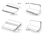
- FIGs. 2A and 2B are simplified illustrations of two views of a multiwall board with a half-depth cut across fiber direction, as used in the modular folding stand 10 according to a preferred embodiment of the present invention.
- Fig. 2A is a view of the multiwall board in a flat mode showing the half-depth cut across the tunnels while Fig. 2B is a view of the multiwall board in a folded mode.
- FIGs. 3A and 3B are simplified illustrations of two views of a multiwall board with a half-depth cut along fiber direction, as used in the modular folding stand 10 according to a preferred embodiment of the present invention.
- Fig. 3A is a view of the multiwall board in a flat mode showing the half-depth cut along a tunnel while Fig. 3B is a view of the multiwall board in a folded mode.
- FIGs. 4, 5, 6, 7, 8, 9, and 10 are simplified illustrations of elements of the modular folding stand 10 according to a preferred embodiment of the present invention.
- Fig. 4 shows a back base in open mode.
- Fig. 5 shows a floor base in open mode.
- Fig. 6 shows a base shelf in open mode.
- Fig. 7 shows a shelf, of which the modular folding stand 10 preferably includes four units, however, any other number is possible.
- Fig. 8 shows a rod, of which the modular folding stand 10 preferably includes four units as there are shelves, however, any other number is possible.
- the rod is preferably an aluminum profile.
- Fig. 9 shows a header
- Fig. 10 shows a stopper, of which the modular folding stand 10 preferably includes four units as there are shelves, however, any other number is possible.
- modular folding stand 10 includes the following elements: Element Quantity Back Base 1 Floor Base 1 Base Shelf 1 Shelf 4 Aluminum Profile 4 Stopper 4 Header 1
- FIGS. 11A, 11B, 12 and 13 are simplified illustration of the back base of Fig. 4 according to a preferred embodiment of the present invention.
- Fig. 11A shows the back base in open mode with a vertical half-cut in the center.
- Fig. 11B shows the back base in closed mode.
- Fig. 12 shows the back base with horizontal fiber direction and the folding half-cuts across the fiber direction.
- Fig. 13 shows the back base with vertical fiber direction and the folding half-cuts along the fiber direction.
- FIGs. 14A, 14B, 15, 16A, and 16B are simplified illustrations of folding details of the modular folding stand 10 according to a preferred embodiment of the present invention.
- Fig. 14A shows the floor base in closed mode.
- Fig. 14B shows the floor base in opened mode.
- Fig. 15 shows the floor base assembled with the back-base in opened mode.
- Fig. 16A is a full view of the assembled back-base and floor base in opened mode.
- Fig. 16B is a full view of the back-base and floor base assembled and folded.
- FIGs. 17A, 17B, 17C and 17D are simplified illustrations of several views of a modular vertical folding stand 11 according to a preferred embodiment of the present invention.
- Fig. 17A is a simplified illustration of a front view of the modular vertical folding stand 11.
- Fig. 17B is a simplified illustration of a side view of the modular vertical folding stand 11.
- Fig. 17C is a simplified illustration of a top view of the modular vertical folding stand 11.
- Fig. 17D is a simplified illustration of an isometric view of the modular vertical folding stand 11.
- the modular vertical folding stand 11 is a display system as described above.
- the modular vertical folding stand 11 is preferably made, at least partly, from multiwall board as described above.
- half-depth cuts into the material as described above with reference to Figs. 2A and 2B .
- Such half-depth cuts enable the folding of the multiwall board.
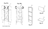
- FIGS. 18A, 18B, 19, 20, and 21 are simplified illustrations of elements of the modular vertical folding stand 11 according to a preferred embodiment of the present invention.
- Fig. 18A shows a back base part 12 in flat-open mode.
- Fig. 18A also shows the fiber direction and two half-depth cuts 13 along the fiber direction enabling the folding of the side parts 14.
- Fig. 18A also shows shelves slots 15.
- Fig. 18B shows the back base part in folded mode, with the side parts folded preferably in 90 degrees.
- Fig. 19 shows a center frame part 16.
- Fig. 20 shows a base floor part 17.
- Fig. 21 shows a shelf part 18.
- FIGS. 22A, 22B and 22C are simplified illustrations of the modular vertical folding stand 11 in various folding modes according to a preferred embodiment of the present invention.
- Fig. 22A shows the modular vertical folding stand 11 assembled in a flat-open mode, with the sides flat-folded and the shelves folded down.
- Fig. 22B shows the modular vertical folding stand 11 assembled in a folded-down (closed) mode, with the sides folded in and the shelves folded down.
- Fig. 22C shows the modular vertical folding stand 11 fully assembled mode, with the sides folded in and the shelves folded up.
- Figs. 18A - 22C may not depict their respective elements, or components, or parts according to the same scale.
- the modular folding stand 10 is typically but preferably made of the following components: Component Quantity Back Base 1 Center Frame 1 Floor Base 1 Shelf 3-4
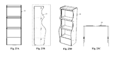
- FIGs. 23A, 23B, 23C and 23D are simplified illustrations of several views of a modular adjustable vertical folding stand 19 according to a preferred embodiment of the present invention.
- Fig. 23A is a simplified illustration of a front view of the modular adjustable vertical folding stand 19.
- Fig. 23B is a simplified illustration of a side view of the modular adjustable vertical folding stand 19.
- Fig. 23C is a simplified illustration of a top view of the modular adjustable vertical folding stand 19.
- Fig. 23D is a simplified illustration of an isometric view of the modular adjustable vertical folding stand 19.
- the modular adjustable vertical folding stand 19 is a display system as described above.
- the modular adjustable vertical folding stand 19 is preferably made, at least partly, from multiwall board as described above.
- half-depth cuts into the material as described above with reference to Figs. 2A and 2B .
- Such half-depth cuts enable the folding of the multiwall board.
- half-depth cuts along the fiber direction such as along a tunnel
- half-depth cuts across the fiber direction are two basic types of half-depth cuts.
- FIGs. 24, 25, 26, 27A, 27B, 28A, 28B and 28C are simplified illustrations of elements of the modular adjustable vertical folding stand 19 according to a preferred embodiment of the present invention.
- Fig. 24 shows a back base part 20 of the modular adjustable vertical folding stand 19 with side parts 21 folded forward.
- the back base part 20 is preferably made of a board of multiwall structure of polypropylene material.
- Fig. 25 shows a shelf part 22 of the modular adjustable vertical folding stand 19.
- the shelf part 22 is preferably made of a board of multiwall structure of polypropylene material.
- Fig. 26 shows a base floor part 23 of the modular adjustable vertical folding stand 19.
- the base floor part 23 is preferably made of a board of multiwall structure of polypropylene material.
- Figs. 27A and 27B are two illustrations of a profile part 24 of the modular adjustable vertical folding stand 19, preferably made of plastic material, preferably solid plastic.
- Fig. 28A, 28B and 28C are three illustrations of a connector part 25 of the modular adjustable vertical folding stand 19, preferably made of plastic material, preferably solid plastic.
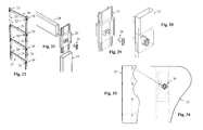
- Figs. 29, 30, 31, 32, 33, and 34 are simplified illustrations of steps of the assembly of the modular adjustable vertical folding stand 19 according to a preferred embodiment of the present invention.
- Fig. 29 shows a connector 25 and a fastener 26.
- Fig. 30 shows the connector 25 with the fastener 26 assembled together.
- Fig. 31 shows the connector 25, two profiles 24 and the fastener 26.
- profile 24 is a tube made of a plastic material.
- a profile 24 is preferably square, but may have other shapes.
- a connector 25 enables the assembly of two or more profiles 24.
- the fastener 26 enables the fastening of a side part 21 to the connector 25.
- Fig. 32 shows an assembled ladder part 27 including connectors 25, profiles 24 and fasteners 26.
- profiles 24 of various lengths it is possible to assemble a ladder of various dimensions and shapes. For example, adjusting the width of the ladder, adjusting the height between the shelves, adjusting the number of shelves, adjusting overall height, etc.
- Fig. 33 shows a side part 21 connected to the ladder part with fasteners 26.
- Fig. 34 is a detail of Fig. 33 showing the side part 21 and a fastener 26.
- the modular adjustable folding stand 19 is typically but preferably made of the following components: Component Quantity Back Base 1 Floor Base 1 Shelf 4 Plastic profile 14 Plastic profile connector 8
- the modular adjustable folding stand 19 when assembled, such as the modular folding stand 10, has folding capabilities as shown and described with reference to Figs. 22A, 22B and 22C . Particularly, The modular adjustable folding stand 19, has upward and downward folding motion as depicted in Figs. 22B and 22C .
- FIGs. 35A, 35B, and 35C are simplified illustrations of a continuously adjustable connector 28, according to a preferred embodiment of the present invention.
- Figs. 36, 37, and 38 are simplified illustrations of the continuously adjustable connector 28 and profiles 29, according to a preferred embodiment of the present invention.
- the continuously adjustable connector 28 and the profiles 29 are preferably made of plastic material, preferably solid plastic. As shown in Figs. 37 and 38 , the continuously adjustable connector 28 may slide over the profile 29 continuously.
- Fig. 36 also shows a fastener 30 for fastening the continuously adjustable connector 28 to a board such as a board made of multiwall structure of polypropylene material, for example, the back base part 20 shown and described with reference to Fig. 24 .
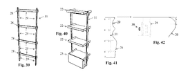
- Fig. 39 is a simplified illustration of a ladder 31, according to a preferred embodiment of the present invention.
- Ladder 31 is made of continuously adjustable connectors 28 and profiles 29 as shown in Fig. 39 .
- Fig. 40 is a simplified illustration of shelves 22 and base floor 23 mounted on a ladder 31, according to a preferred embodiment of the present invention.
- Fig. 41 is a simplified illustration of the side 21 of the back base part 20 connected to the ladder 31, and to Fig. 42 , which is a simplified illustration of a detail of Fig. 41 , showing the side 21 connected to a connector 28 of the ladder 31 using a fastener 30, according to a preferred embodiment of the present invention.
- the modular adjustable folding stand assembled using the continuously adjustable connector 28 has folding capabilities as shown and described with reference to Figs. 22A, 22B and 22C . Particularly, This modular adjustable folding stand, has upward and downward folding motion as depicted in Figs. 22B and 22C .
- the modular adjustable folding stand is typically but preferably made of the following components: Component Quantity Back Base 1 Floor Base 1 Shelf 4 Plastic profile 14 Plastic profile connector 8
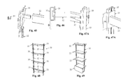
- FIGs. 43A, and 43B are simplified illustrations of a reverse-T profile 32, according to a preferred embodiment of the present invention.
- Figs. 44A, 44B and 44C are simplified illustrations of different views of a continuously adjustable connector 33 compatible with profile 32, according to a preferred embodiment of the present invention.
- Figs. 45, 46, 47A and 47B are simplified illustrations of the continuously adjustable connector 33 and profiles 32, according to a preferred embodiment of the present invention.
- the continuously adjustable connector 33 and the profiles 32 are preferably made of plastic material, preferably solid plastic. As shown in Figs. 46, 47A and 47B , the continuously adjustable connector 33 may slide over the profile 32 continuously.
- Fig. 45 also shows a fastener 34 for fastening the continuously adjustable connector 28 to a board such as a board made of multiwall structure of polypropylene material, for example, the back base part 20 shown and described with reference to Fig. 24 .
- Fig. 48 is a simplified illustration of a ladder 35, according to a preferred embodiment of the present invention.
- Ladder 35 is made of continuously adjustable connectors 33 and profiles 32 as shown in Fig. 48 .
- Fig. 49 is a simplified illustration of shelves 22 and base floor 23 mounted on a ladder 31, according to a preferred embodiment of the present invention.
- the modular adjustable folding stand assembled using the continuously adjustable connector 28 has folding capabilities as shown and described with reference to Figs. 22A, 22B and 22C . Particularly, This modular adjustable folding stand, has upward and downward folding motion as depicted in Figs. 22B and 22C .
- the modular adjustable folding stand is typically but preferably made of the following components: Component Quantity Back Base 1 Floor Base 1 Shelf 4 Plastic profile 14 Plastic profile connector 8
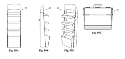
- Figs. 50A, 50B, 50C and 50D are simplified illustrations of several views of a fully folding stand 36 according to a preferred embodiment of the present invention.
- Fig. 50A is a simplified illustration of a front view of the fully folding stand 36.
- Fig. 50B is a simplified illustration of a side view of the fully folding stand 36.
- Fig. 50C is a simplified illustration of a top view of the fully folding stand 36.
- Fig. 50D is a simplified illustration of an isometric view of the fully folding stand 36.
- the fully folding stand 36 is a display system as described above.
- the fully folding stand 36 is preferably made, at least partly, from multiwall board as described above.
- half-depth cuts into the material as described above with reference to Figs. 2A and 2B .
- Such half-depth cuts enable the folding of the multiwall board.
- FIGS. 51, 52, 53, 54, 55, 56, 57, 58, 59, and 60 are simplified illustrations of elements of the fully folding stand 36, according to a preferred embodiment of the present invention.
- Fig. 51 is a simplified illustrations of a back part 37 of the fully folding stand 36.
- Fig. 52 is a simplified illustrations of a beam part 38 of the fully folding stand 36.
- Fig. 53 is a simplified illustrations of a base part 39 of the fully folding stand 36.
- Fig. 54 is a simplified illustrations of a base shelf part 40 of the fully folding stand 36.
- Fig. 55 is a simplified illustrations of a shelf part 41 of the fully folding stand 36.
- Fig. 56 is a simplified illustrations of a profile part 42 of the fully folding stand 36.
- Fig. 57 is a simplified illustrations of a header part 43 of the fully folding stand 36.
- Fig. 58 is a simplified illustrations of a header support part 44 of the fully folding stand 36.
- Fig. 59 is a simplified illustrations of a shelf cover part 45 of the fully folding stand 36.
- Fig. 60 is a simplified illustrations of a stand handle part 46 of the fully folding stand 36.
- parts 37 to 46 are made of multiwall structure of polypropylene material.
- Profile 42 is preferably made from aluminum.
- Figs. 61, 62, and 63 are a simplified illustrations of three configurations of the back part 37, the beam part 38, and the base part 39 assembled together, according to a preferred embodiment of the present invention.
- Figs. 61-63 are three folding positions.
- Fig. 61 shows the assembled parts 37, 38, and 39 in a flat open folding configuration (for example for storage or transportation).
- Fig. 62 shows the assembled parts 37, 38, and 39 in a back-folded configuration (for example for storage or transportation).
- Fig. 63 shows the assembled parts 37, 38, and 39 in a positioning configuration (for example for display).
- Figs. 61-63 also show the preferred fiber direction.
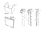
- FIG. 64A and Fig. 64B are simplified illustrations of two folding configurations of the back part 37 according to a preferred embodiment of the present invention.
- Fig. 64A show the back part 37 in open configuration while Fig. 64B show the back part 37 in closed or folded configuration.
- Arrows in Fig. 64A and 64B show the directions of the folding motion.
- Figs. 65A, 65B, and 65C are simplified illustrations of three folding position of the assembled back part 37 and beam part 38, according to a preferred embodiment of the present invention.
- Fig. 65A shows the beam part 38 folded behind the back part 37.
- Fig. 65B shows the beam part 38 folded in front of the back part 37, and
- Fig. 65C shows the beam part 38 folded in a right angle to the back part 37.
- Arrows in Figs. 65A and 65B show the folding motion while numeral 47 indicates the pivoting axle.
- the modular adjustable folding stand 36 assembled has folding capabilities as shown and described above.
- the modular adjustable folding stand is typically but preferably made of the following components: Component Quantity Back Base 1 Back handle 1 Beam 2 Floor Base 1 Shelf 3 Shelf cover 3 Aluminum profile 3 Header support 4 Header 1
- the purpose of the present invention is a display system, which is a device for storing one or more articles for display.
- the device is usually used as a point of sale display, or point of sale stand. More particularly, but not exclusively, the purpose of the present invention is provide a foldable construction for presenting articles for sale.
- a display system according to the present invention is foldable to be comfortably carried around, easy to unfold and place in site, and large and stable enough to carry a large number of articles.
- a display system includes the following main parts: a ladder part, an envelop part, and one or more shelves. Additionally and optionally the display system may include one or more fastener parts, one or more support parts, and one or more accessory parts.
- the ladder part preferably provides for carrying the weight of the articles presented
- the ladder part is preferably produced from a rigid material, preferably from metal or plastic material, preferably in the shape of a ladder constructed from vertical parts, horizontal parts and joints (connectors).
- the vertical and horizontal parts are preferably in the form of tubes that may have round or rectangular shape (cut) or any other type of profile (such as element 32).
- the tubes may have different lengths and the joints (connectors) enable the constructions of ladder parts of different heights and widths.
- ladder parts can be made from other materials such as multiwall sheets, preferably using support parts.
- Ladder part (center frame) 16 is preferably made of multiwall polypropylene material.
- Ladder parts 27, 31 and 35 are made of plastic tubes 24, 29, and 32, and joints (connectors) 25, 28, 33.
- Center frame part 16 is an example of a ladder part made from multiwall polypropylene material.
- the purpose of the ladder part is to carry the weight of the shelves (and the articles the store) to the floor.
- the envelop part does not carry weight.
- the envelop part provides the display system with stability, decorative value, and area for advertising the articles presented.
- the envelop part is preferably produced from light, flat and foldable material, preferably from plastic sheet, such as multiwall polypropylene board as described above. Easy folding of the envelop part is preferably provided using half-depth cuts through the multiwall structure as described above with reference to Figs. 2A, 2B, 3A, and 3B . Since the ladder part has two legs it is inherently unstable.
- the envelope part provides stability by eliminating the titling of the ladder part by providing at least one more contact area with the floor. Preferably the contact area with the floor is large enough to eliminate excessive pressure on any part of the envelop part so that the envelop part, which is relatively thin and flexible, does not collapse.
- envelop parts are shown and described above with reference to Fig. 4 , Figs. 11A and 11B , element 12 (of Figs. 18A, 18B and 22A - 22C ), element 20 (of Fig. 24 ), element 31 (of Figs. 39 - 41 ), element 35 (of Figs. 48 - 49 ) and elements 37 and 38 (of Figs. 61 - 65C ).
- the envelop part is preferably constructed of a back base part (or back part) and two beam parts (or side parts).
- the beam or side parts are attached to the ladder part with fasteners.
- the back parts include slots to accommodate flap parts of the shelves.
- Each of the shelf parts preferably rests on a horizontal part of the ladder part and is balanced by the envelop, preferably by inserting a flap part of the shelf into a slot provided in the back base part of the envelop.
- the ladder part is positioned so that the horizontal part supports the shelf part at an optimal point to avoid collapsing of the shelf or envelop parts. Such optimal position may be at the middle of the shelf part.
- Joint (connector) parts connect horizontal and vertical parts to form ladder parts.
- Joint parts preferably also provide for fasteners, preferably to fasten the envelop part to the ladder part.
- a support part examples are provided by the rod part of Fig. 8 as well as element 42 of Fig. 56 . These support parts support a shelf part by conveying the weight to the envelop part.
- accessory parts such as a base part, a head part, etc. are shown and described above with reference to the elements of Figs. 5-7, 9, 10 , 14A and 14B , element 17 of Fig. 20 , elements 39, 40, and 43 - 46 of Figs. 53, 54 and 57 - 60 , respectively as well as element 39 of Figs. 61 - 64B .
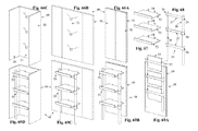
- FIGs. 66A, 66B, 66C, 67, 68, 69A, 69B, 69B, 69C, and 69D are a simplified illustrations of a display system 48 according to a preferred embodiment of the present invention.
- Fig. 66A shows a back view of the envelope 49 of the display system 48 in the closed-back mode with the side panels 50 folded behind the back panel 51.
- Fig. 66B shows a front view of the envelope 49 in the flat-open mode with the side panels 50 opened in-line with the back panel 51.
- Fig. 66B also shows slots 52.
- Fig. 66C shows a front view of the envelope 49 in the open (positioned) mode with the side panels 50 at right-angles with the back panel 51 (front-fold mode).
- Fig. 67 shows a shelves 53 of the display system 50 with flaps 54.
- Fig. 68 shows a ladder part 55 of the display system 50 with vertical parts 56, horizontal pats 57 and joints (connectors) 58.
- Fig. 69A shows the display system 50 assembled with the envelope part 49, the shelves 53, and the ladder part 55, and folded closed in with the envelop in the fold-back mode and the ladder and shelves folded up to minimize the volume consumed by the display system 50.
- this mode it is convenient and economical to store the display system 50 or to carry it around. It is appreciated that the ladder and shelves can also be folded down to preserve space and that the envelop can be in the flat-open mode.
- Fig. 69B shows the display system 50 with the envelop in the fold-back mode and the ladder and shelves folded down to position the display system 50 in place.
- Fig. 69C shows the display system 50 with the envelop in the flat open mode and the ladder and shelves folded down.
- Fig. 69D shows the display system 50 assembled and positioned in place with the envelop in the front-fold mode and preferably connected to the ladder part with fasteners (not shown).
- the display system 50 is preferably constructed in a manner that enables the side parts (beam parts) to fold back and forth with relation to the back part.
- the beam parts may be folded along the back part, or behind the back part, to provide a flat surface.
- This closed mode (configuration) preferably consumes minimal volume, is easy to carry around, to store and to stack, as shown in Fig. 69A .
- the beam parts may also be folded in right angle to the back part, or a similar angle.
- This open (positioned) mode (configuration) preferably enables the display system to be positioned vertically, that provides stability to the display system, and supports the shelves horizontally, as shown in Fig. 69D .
- the display system 50 is preferably constructed in a manner that enables folding the system into the closed mode where the ladder part and the shelves folds upwards (as shown in Fig. 69A ) or downwards, to reduce the volume consumed.
- Figs. 70A, 70B, and 70B are simplified illustration of side views of the display system 50 in different folding modes according to a preferred embodiment of the present invention.
- Fig. 70A shows the display system 50 in a fold-down mode.
- Fig. 70B shows the display system 50 in a fold-up mode.
- Fig. 70C shows the display system 50 in the open (positioned) mode (but with the side removed for clarity).
- Fig. 70A-70C show a virtual parallelogram 59, and a cut 60 of a virtual box representing the volume consumed by the display system 50 in each mode.
- the ladder part, the back part and the shelves form together parallelogram 59, which changes between the closed folding mode (for storing and carrying) and the open folding mode (for positioning) affecting the parallelogram's angles.
- the shelves are coupled with the envelop part and with the ladder part to enable folding, and that the folding enables one folding mode (positioning mode) enabling placement of articles on the shelves and another folding mode (closed mode) consuming a volume smaller than the volume of said first folding mode.
- the open folding mode separates between said back part and said ladder part and the closed folding mode bring the back part and the ladder part closer to preserve space.
- ladder part 55 is made of a rigid material and the envelop part 49, and optionally the shelves 53 too, are made of a light, thin and optionally flexible material such as multiwall structure of polypropylene material.
- the ladder part 55 includes a rigid vertical part 56, and a rigid horizontal part 57 made from a vertically flat material such as multiwall structure of polypropylene material. Therefore, the display system may include a ladder part, and/or an envelop part, and/or a shelve part made of a multiwall structure of polypropylene material or any other type of plastic sheet or plastic board.
- the envelop part 49 preferably includes a plurality of slots 52, and the shelves 53 preferably includes flaps or tabs 54 that are insertable into the slots 52.
- the flap 54 when inserted into a slot 52 provides an axle 61 about which the shelf 53 may be rotated relative to the envelop part 49 to enable upward and/or downward folding of the shelves as well as the entire display system 50 as further shown in Figs. 70A and 70B .
- the display system preferably includes at least one fastener part such as elements 26, 30, and 34 (respectively).
- the fastener parts are used for fastening the envelop part to the ladder part, preferably at the joints.
- Such fastener parts may have the shape of a rivet, a slotted spring pin, a bayonet type clamp, a magnet or a pair of magnets, etc.
- the display system includes an envelop part 49 that includes a back part 51 and at least one side part 50 that is foldable with respect to the back part.
- the envelop is made of a multiwall of polypropylene board or a similar material and a fold is provided between the back part and the side part where the fold is made of a half-depth cut though the multiwall structure.
- the fold enables folding the side part along the back part, and/or in parallel to the back part, and/or forming an angle with the back part.
- the display system is constructed with connector parts (joints) 58 that may connect two vertical parts, and/or a vertical part and a horizontal part, and/or a vertical part and an envelope part.
- the display system is constructed with connector parts (joints) that can slide on the vertical part so that the horizontal parts, and/or the shelves, can be positioned flexibly and continuously. It is appreciated that such connector part may use a dovetail joint.
- Fig. 71 is a simplified illustration of a ladder and shelves according to a preferred embodiment of the present invention.
- the display system is constructed so that the shelves 53 are positioned over the ladder part 55 to transfer the weight of the article stored on the shelves to the horizontal parts 57 of the ladder part, and the horizontal parts are coupled to transfer the weight to the vertical parts 56, and the vertical parts are positioned to transfer the weight to the floor.
Landscapes
- Life Sciences & Earth Sciences (AREA)
- Engineering & Computer Science (AREA)
- Wood Science & Technology (AREA)
- Display Racks (AREA)
- Assembled Shelves (AREA)
Applications Claiming Priority (2)
| Application Number | Priority Date | Filing Date | Title |
|---|---|---|---|
| US201161510500P | 2011-07-22 | 2011-07-22 | |
| US201161550937P | 2011-10-25 | 2011-10-25 |
Publications (2)
| Publication Number | Publication Date |
|---|---|
| EP2548477A2 true EP2548477A2 (de) | 2013-01-23 |
| EP2548477A3 EP2548477A3 (de) | 2014-11-26 |
Family
ID=46583870
Family Applications (1)
| Application Number | Title | Priority Date | Filing Date |
|---|---|---|---|
| EP12177548.0A Withdrawn EP2548477A3 (de) | 2011-07-22 | 2012-07-23 | Modularer zusammenklappbarer Stand |
Country Status (1)
| Country | Link |
|---|---|
| EP (1) | EP2548477A3 (de) |
Cited By (2)
| Publication number | Priority date | Publication date | Assignee | Title |
|---|---|---|---|---|
| WO2017089989A1 (en) | 2015-11-25 | 2017-06-01 | Faster Displays Llc | Optimized folding display |
| WO2024033689A1 (en) | 2022-08-10 | 2024-02-15 | Faster Displays Llc | Optimized folding display |
Family Cites Families (4)
| Publication number | Priority date | Publication date | Assignee | Title |
|---|---|---|---|---|
| US4582003A (en) * | 1984-10-09 | 1986-04-15 | Ultimate Display Corporation | Folding corrugated board display shelving |
| US5273169A (en) * | 1991-08-14 | 1993-12-28 | Maglione Stephan T | Corrugated display stand |
| SE9403470L (sv) * | 1994-10-13 | 1996-04-14 | Rolf Nystroem | Hopfällbar möbel |
| US6302283B1 (en) * | 2000-07-21 | 2001-10-16 | Wen-Chun Yeh | Display rack |
-
2012
- 2012-07-23 EP EP12177548.0A patent/EP2548477A3/de not_active Withdrawn
Non-Patent Citations (1)
| Title |
|---|
| None |
Cited By (3)
| Publication number | Priority date | Publication date | Assignee | Title |
|---|---|---|---|---|
| WO2017089989A1 (en) | 2015-11-25 | 2017-06-01 | Faster Displays Llc | Optimized folding display |
| US10624472B2 (en) | 2015-11-25 | 2020-04-21 | Faster Displays Llc | Optimized folding display |
| WO2024033689A1 (en) | 2022-08-10 | 2024-02-15 | Faster Displays Llc | Optimized folding display |
Also Published As
| Publication number | Publication date |
|---|---|
| EP2548477A3 (de) | 2014-11-26 |
Similar Documents
| Publication | Publication Date | Title |
|---|---|---|
| US9204738B2 (en) | Modular folding stand | |
| CA1064258A (en) | Portable display apparatus | |
| US12102241B2 (en) | Floorstand with shelf support | |
| US5483779A (en) | Header frame for a display system | |
| US10568439B2 (en) | Semi-automatic assembly display hutch | |
| US20120304515A1 (en) | Tradeshow display system | |
| JPH01111976A (ja) | 携行用展示パネル及び蝶番装置 | |
| US3608221A (en) | Display panel | |
| CA2821531A1 (en) | Foldable shelving unit and method for deploying and compacting same | |
| US7070057B2 (en) | Foldable display stand with self erecting stabilizing base | |
| EP3379979B1 (de) | Anzeige mit optimierter faltung | |
| EP2548477A2 (de) | Modularer zusammenklappbarer Stand | |
| US20230100359A1 (en) | Portable and foldable workstation apparatus | |
| KR20050002800A (ko) | 미니 마켓용 테이블 | |
| WO2010081442A1 (en) | Folding stand | |
| US20170265655A1 (en) | Foldable display units | |
| US11412844B1 (en) | Table assembly | |
| US7918351B2 (en) | Quick-assembly shelf mechanism for optical media | |
| US20110266239A1 (en) | Display with multiple nesting components | |
| KR20120055567A (ko) | 포장 용기 | |
| AU2013405738A1 (en) | Collapsible display shelf | |
| CN213054786U (zh) | 一种可调节料架 | |
| CN212897778U (zh) | 一种模块化展位 | |
| CN222622581U (zh) | 一种模块化组合式展柜 | |
| CN220512438U (zh) | 可折叠美术教学桌 |
Legal Events
| Date | Code | Title | Description |
|---|---|---|---|
| PUAI | Public reference made under article 153(3) epc to a published international application that has entered the european phase |
Free format text: ORIGINAL CODE: 0009012 |
|
| AK | Designated contracting states |
Kind code of ref document: A2 Designated state(s): AL AT BE BG CH CY CZ DE DK EE ES FI FR GB GR HR HU IE IS IT LI LT LU LV MC MK MT NL NO PL PT RO RS SE SI SK SM TR |
|
| AX | Request for extension of the european patent |
Extension state: BA ME |
|
| PUAL | Search report despatched |
Free format text: ORIGINAL CODE: 0009013 |
|
| AK | Designated contracting states |
Kind code of ref document: A3 Designated state(s): AL AT BE BG CH CY CZ DE DK EE ES FI FR GB GR HR HU IE IS IT LI LT LU LV MC MK MT NL NO PL PT RO RS SE SI SK SM TR |
|
| AX | Request for extension of the european patent |
Extension state: BA ME |
|
| RIC1 | Information provided on ipc code assigned before grant |
Ipc: A47F 5/11 20060101AFI20141023BHEP |
|
| STAA | Information on the status of an ep patent application or granted ep patent |
Free format text: STATUS: THE APPLICATION IS DEEMED TO BE WITHDRAWN |
|
| 18D | Application deemed to be withdrawn |
Effective date: 20150527 |