EP2548368B1 - Portrait image synthesis from multiple images captured on a handheld device - Google Patents
Portrait image synthesis from multiple images captured on a handheld device Download PDFInfo
- Publication number
- EP2548368B1 EP2548368B1 EP11799254.5A EP11799254A EP2548368B1 EP 2548368 B1 EP2548368 B1 EP 2548368B1 EP 11799254 A EP11799254 A EP 11799254A EP 2548368 B1 EP2548368 B1 EP 2548368B1
- Authority
- EP
- European Patent Office
- Prior art keywords
- face
- image
- user
- delimiter
- camera
- Prior art date
- Legal status (The legal status is an assumption and is not a legal conclusion. Google has not performed a legal analysis and makes no representation as to the accuracy of the status listed.)
- Active
Links
- 230000015572 biosynthetic process Effects 0.000 title description 2
- 238000003786 synthesis reaction Methods 0.000 title description 2
- 230000003287 optical effect Effects 0.000 claims description 6
- 230000008859 change Effects 0.000 claims description 2
- 230000001815 facial effect Effects 0.000 description 9
- 210000000887 face Anatomy 0.000 description 7
- 230000006870 function Effects 0.000 description 5
- 230000000994 depressogenic effect Effects 0.000 description 4
- 210000003128 head Anatomy 0.000 description 4
- 238000000926 separation method Methods 0.000 description 4
- 238000010586 diagram Methods 0.000 description 3
- 238000006073 displacement reaction Methods 0.000 description 3
- 230000000694 effects Effects 0.000 description 3
- 238000000034 method Methods 0.000 description 3
- 238000012805 post-processing Methods 0.000 description 3
- 230000008569 process Effects 0.000 description 3
- 230000004044 response Effects 0.000 description 3
- 238000003384 imaging method Methods 0.000 description 2
- 230000000717 retained effect Effects 0.000 description 2
- 230000004397 blinking Effects 0.000 description 1
- 238000001514 detection method Methods 0.000 description 1
- 230000007246 mechanism Effects 0.000 description 1
- 230000002093 peripheral effect Effects 0.000 description 1
- 230000002085 persistent effect Effects 0.000 description 1
- 238000003825 pressing Methods 0.000 description 1
- 238000012545 processing Methods 0.000 description 1
- 238000005070 sampling Methods 0.000 description 1
- 230000000007 visual effect Effects 0.000 description 1
Images


Classifications
-
- H—ELECTRICITY
- H04—ELECTRIC COMMUNICATION TECHNIQUE
- H04N—PICTORIAL COMMUNICATION, e.g. TELEVISION
- H04N23/00—Cameras or camera modules comprising electronic image sensors; Control thereof
- H04N23/60—Control of cameras or camera modules
- H04N23/64—Computer-aided capture of images, e.g. transfer from script file into camera, check of taken image quality, advice or proposal for image composition or decision on when to take image
-
- H—ELECTRICITY
- H04—ELECTRIC COMMUNICATION TECHNIQUE
- H04N—PICTORIAL COMMUNICATION, e.g. TELEVISION
- H04N13/00—Stereoscopic video systems; Multi-view video systems; Details thereof
- H04N13/10—Processing, recording or transmission of stereoscopic or multi-view image signals
- H04N13/106—Processing image signals
- H04N13/156—Mixing image signals
-
- H—ELECTRICITY
- H04—ELECTRIC COMMUNICATION TECHNIQUE
- H04N—PICTORIAL COMMUNICATION, e.g. TELEVISION
- H04N13/00—Stereoscopic video systems; Multi-view video systems; Details thereof
- H04N13/20—Image signal generators
- H04N13/204—Image signal generators using stereoscopic image cameras
- H04N13/207—Image signal generators using stereoscopic image cameras using a single 2D image sensor
- H04N13/221—Image signal generators using stereoscopic image cameras using a single 2D image sensor using the relative movement between cameras and objects
-
- H—ELECTRICITY
- H04—ELECTRIC COMMUNICATION TECHNIQUE
- H04N—PICTORIAL COMMUNICATION, e.g. TELEVISION
- H04N23/00—Cameras or camera modules comprising electronic image sensors; Control thereof
- H04N23/60—Control of cameras or camera modules
- H04N23/61—Control of cameras or camera modules based on recognised objects
- H04N23/611—Control of cameras or camera modules based on recognised objects where the recognised objects include parts of the human body
-
- H—ELECTRICITY
- H04—ELECTRIC COMMUNICATION TECHNIQUE
- H04N—PICTORIAL COMMUNICATION, e.g. TELEVISION
- H04N23/00—Cameras or camera modules comprising electronic image sensors; Control thereof
- H04N23/60—Control of cameras or camera modules
- H04N23/62—Control of parameters via user interfaces
-
- H—ELECTRICITY
- H04—ELECTRIC COMMUNICATION TECHNIQUE
- H04N—PICTORIAL COMMUNICATION, e.g. TELEVISION
- H04N23/00—Cameras or camera modules comprising electronic image sensors; Control thereof
- H04N23/60—Control of cameras or camera modules
- H04N23/63—Control of cameras or camera modules by using electronic viewfinders
- H04N23/633—Control of cameras or camera modules by using electronic viewfinders for displaying additional information relating to control or operation of the camera
- H04N23/635—Region indicators; Field of view indicators
-
- H—ELECTRICITY
- H04—ELECTRIC COMMUNICATION TECHNIQUE
- H04N—PICTORIAL COMMUNICATION, e.g. TELEVISION
- H04N23/00—Cameras or camera modules comprising electronic image sensors; Control thereof
- H04N23/60—Control of cameras or camera modules
- H04N23/667—Camera operation mode switching, e.g. between still and video, sport and normal or high- and low-resolution modes
-
- H—ELECTRICITY
- H04—ELECTRIC COMMUNICATION TECHNIQUE
- H04N—PICTORIAL COMMUNICATION, e.g. TELEVISION
- H04N23/00—Cameras or camera modules comprising electronic image sensors; Control thereof
- H04N23/60—Control of cameras or camera modules
- H04N23/698—Control of cameras or camera modules for achieving an enlarged field of view, e.g. panoramic image capture
Definitions
- This invention relates to the synthesis of an enhanced portrait image from at least two images captured on a handheld digital image capture device.
- US 6 094 215 A and GB 2 405 764 A disclose prior art for assisting the user in capturing a stereoscopic image pair using a camera having a single image sensor.
- US 2010/0188560 A1 discloses a hand-held digital image capture device according to the precharacterizing portion of claim 1.
- a hand-held digital image capture device characterized according to claim 1.
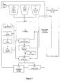
- FIG. 1 is a block diagram of a hand-held digital image acquisition device 20.
- the device 20 is a hand-held digital camera as such, but it could be the camera part of a cell phone or other hand-held device incorporating a digital camera function. All such devices are referred to herein as cameras for convenience whether or not that is their main function.
- the camera 20 includes a digital processor 120. As is well known, many of the processes performed in or by the digital camera may be implemented in or controlled by software operating in the processor 120, including user interface functions and control of peripheral components such as buttons and display screen.
- the processor 120 in response to a user input at 122, such as half pressing a shutter button (pre-capture mode 32), initiates and controls the digital photographic process.
- Ambient light exposure is monitored using light sensor 40 in order to automatically determine if a flash is to be used.
- a distance to the subject is determined using a focus component 50 which also focuses the image on image capture component 60.
- processor 120 causes the flash 70 to generate a photographic flash in substantial coincidence with the recording of a high resolution image by image capture component 60 upon full depression of the shutter button.
- the image capture component 60 digitally records the image in colour.
- the image capture component preferably includes a CCD (charge coupled device) or CMOS to facilitate digital recording.
- the flash may be selectively generated either in response to the light sensor 40 or a manual input 72 from the user of the camera.
- the high resolution image recorded by image capture component 60 is stored in an image store 80 which may comprise computer memory such a dynamic random access memory or a nonvolatile memory.
- the camera is equipped with a digital display screen 100, such as an LCD, for preview and post-view of images.
- the display screen 100 may be an electronic viewfinder screen or it may be an external screen, usually placed on the rear of the camera body.
- Temporary storage 82 may be used to store one or more of the preview images and can be part of the image store 80 or a separate component.
- the preview images are preferably generated by the image capture component 60.
- preview images preferably have a lower pixel resolution than the main image taken when the shutter button is fully depressed, and are generated by sub-sampling a raw captured image using software 124 which can be part of the general processor 120 or dedicated hardware or combination thereof.
- the camera 20 has a user-selectable "Enhanced portrait” mode.
- the camera is caused to automatically capture and store a series of images while the user moves around a concave path centred on the face of one of the human subjects to be imaged.
- the captured images are then processed to synthesise an enhanced portrait image.
- a shallow depth of field may be selected to throw the background out of focus. However this is not normally needed as will be explained shortly.
- Such motion along a concave path may not be a natural one for the user to follow. It may be challenging even for an experienced researcher to correctly sweep the handheld device through such a path. Therefore, such movement is assisted in the following manner using the face delimiter 208.
- the size and position of the face delimiter 208 is thereafter fixed on the display screen throughout the movement along the path P.
- This fixed face delimiter 208 assists the user in maintaining the camera 20 on the path P by allowing the user to attempt to maintain the face image 210 within and occupying the full width and height of the delimiter 208 at all times.
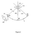
- Figures 4a, 4b and 4c show the face delimiter 208 and face image 210 when the camera 20 is correctly positioned at points A, B and C respectively on the path P, Figure 2 , with the optical axis pointing directly towards the face.
- the face image 210 substantially fills the delimiter 208 and does not extend outside it.
- Figures 6(c) and 6(d) show the results of the camera being respectively too far away from, and too near to, the subject 204. This would indicate to the user that he has to bring the camera nearer to or further from the subject 204 in order to properly fill and centre the face image 210 in the delimiter 208. Alternatively, the face image 208 could be maintained properly filling the delimiter 208 by automatically zooming the camera lens as appropriate, although this would not adequately compensate for gross deviations in distance due to the effects of perspective.
- At least two images at an optimal stereoscopic displacement are required.
- the stereo displacement depends on the distance to the face (which can be determined with sufficient accuracy from the face size) and for most realistic generation of a 3D stereoscopic portrait it is ideally equal to the separation of the eyes in a person. However it may be desirable to capture at a greater separation to emphasize the 3D portrait. It is also generally desirable to capture a plurality stereoscopic pairs in case the subject is blinking in one image of a pair and not in the other.
- the user 200 releases the shutter button when the camera reaches position C, Figure 2 , having a three quarter view of the head 202 from the opposite side to the position A, or earlier if an indication of a successful sweep is given.
- the shutter release ends the image capture function of the enhanced portrait mode.
- the shutter instead of holding the shutter down during the entire sweep along the path P, the shutter could be briefly depressed at the start and briefly depressed again at the end to indicate the end of the sweep..
- a background taken from an image frame captured between the left-hand and right-hand images of the main stereoscopic image pair This additonal image is referred to as an intermediate image as it lies between the left-hand and right-hand images of a stereo pair.
- the left-hand image is retained, but the facial region from the right-hand image is separated from the background and composited over the facial region of the intermediate image.
- the background blur maybe refined by separating the facial images and foreground region of each image in the stereo pair from the respective background.
- the two backgrounds may then be initially aligned and disparity and depth map calculations may be used to more selectively determine near and far background regions.
- Both background regions may then be selectively un-aligned or selectively blurred or both, based on the determined pixel disparities and or depth maps to provide a more convincing 3D Bokeh effect.
- the original facial images are then re-composited over their respective backgrounds to provide a more convincing 3D portrait. Where one or both of the modified backgrounds do not exactly match the original facial image and foreground region then matching portions of the other background image may be composited to fill in such voids.
- the device may simply capture an enhanced Bokeh effect 2D portrait, by performing the same process, creating depth map and choosing only one still image to use the depth map and blur the background, while keeping the foreground object.
- multiple stereo pairs may be captured as the camera traces the concave path, enabling a pseudo-3D slideshow of the subject to be created.
- the pairs may be stored either in the form of multi-image still format or in a movie 3D format.
- this slideshow may be subject to additional post-processing to generate a more sophisticate 3D model of the person, or to perform advanced pseuro-3D facial recognition
- a plurality of matching stereo pairs may be retained to allow a 3D portrait sweep slideshow to be prepared. This may require additional post-processing, but if the cameras has a sufficiently powerful CPU it may be prepared and viewed in-camera.
- the user perspective on the 3D sweep portrait may be varied by moving the imaging device, and detecting its motion using an internal sensor or otherwise. As the imaging device is moved the display cycles forward, or backward, through the multiple stereo pairs in the slideshow according to the motion of the device. Note that this requires the user to move their head together with the device to maintain their position relative to the auto-stereoscopic display.
- an auto-stereoscopic 3D display e.g. Nintendo 3DS
- Post-processing of the stored images, as described above, is performed in an enhanced portrait mode processor 90.
- the processor 90 can be integral to the camera 20 (for example, it could be the processor 120 with suitable programming) or part of an external processing device 10 such as a desktop computer. Where the processor 90 is integral to the camera 20, the final processed image may be displayed on the image display screen 100, saved on a persistent storage 112 which can be internal or a removable storage such as CF card, SD card or the like, or downloaded to another device via image output means 110. In embodiments where the processor 90 is implemented in an external device 10, the final processed image may be returned to the camera 20 for storage and display as described above, or stored and displayed externally of the camera.
- the camera is initially pointed at, and during movement along the path P is maintained pointing at, the face of one of the subjects, e.g. using a face priority based mechanism, or the face may be selected by the user. That individual face will be used as point of reference to have minimum parallax in creating the consequent depth map. Additional faces may be detected and information from such additional detected faces (e.g. size, eye location and facial orientation) helps to improve the accuracy of the depth map.
- additional faces will increase/decrease and the location of eyes and other facial features provides information about changes in orientation of these additional faces. This information indicates the relative depth of such additional faces relative to the main subject and facilitates the separation of these faces from the scene background.
- more than two images may be captured to facilitate the creation of a final optimized stereoscopic image.
- stereo image pairs, optimized for each additional face may be acquired in addition to the stereo image pair for the main face. These will be acquired based on the relative depth of each additional face relative to the main face.
- the centre of rotation of the concave path is not necessarily at the subject's face.
- the path may be modified according to the distance of the camera from the face.
- a shorter radius of curvature than the actual distance to the face may be used as this exaggerates the disparity between the stereo pair (which is reduced at greater distances); when the face is in close-up then a longer radius of curvature may be used to reduce the disparity (which is increased) and obtain a more optimal stereo pair.
- a longer radius of curvature may also be used for the sweep when there are multiple faces to optimize the acquisition of suitable stereo pairs for each face.
- the user is not aware of the radius of curvature, but is directed to sweep at the correct radius using the position of the face 210 within the face delimiter 208 as shown in Figure 3 , the size of the delimiter being dynamically adjusted by the camera according to the desired path which the user is expected to take based upon the initial position of the user relative to the face.
- Embodiments of the invention provide a means to easily and accurately separate foreground and background regions of a scene, determine a detailed and accurate depth map of the scene and optionally capture at least one stereoscopic image pair of the foreground object(s) of the scene.
- Embodiments further provide means to selectively blur the background regions according to their relative depths and recomposit them with the extracted foreground regions or, alternatively with a stereoscopic pair of the foreground, to create an enhanced portrait image.
Description
- This invention relates to the synthesis of an enhanced portrait image from at least two images captured on a handheld digital image capture device.
US 6 094 215 A andGB 2 405 764 A -
US 2010/0188560 A1 discloses a hand-held digital image capture device according to the precharacterizing portion of claim 1. - According to the present invention there is provided a hand-held digital image capture device characterized according to claim 1.
- Embodiments of the invention will now be described, by way of example, with reference to the accompanying drawings, in which:
-
Figure 1 is a block diagram of a digital camera embodying the present invention. -
Figures 2 to 6 are schematic diagrams illustrating the operation of the camera. -
FIG. 1 is a block diagram of a hand-held digitalimage acquisition device 20. In the present embodiment thedevice 20 is a hand-held digital camera as such, but it could be the camera part of a cell phone or other hand-held device incorporating a digital camera function. All such devices are referred to herein as cameras for convenience whether or not that is their main function. - The
camera 20 includes adigital processor 120. As is well known, many of the processes performed in or by the digital camera may be implemented in or controlled by software operating in theprocessor 120, including user interface functions and control of peripheral components such as buttons and display screen. - The
processor 120, in response to a user input at 122, such as half pressing a shutter button (pre-capture mode 32), initiates and controls the digital photographic process. Ambient light exposure is monitored usinglight sensor 40 in order to automatically determine if a flash is to be used. A distance to the subject is determined using a focus component 50 which also focuses the image onimage capture component 60. If a flash is to be used,processor 120 causes theflash 70 to generate a photographic flash in substantial coincidence with the recording of a high resolution image byimage capture component 60 upon full depression of the shutter button. Theimage capture component 60 digitally records the image in colour. The image capture component preferably includes a CCD (charge coupled device) or CMOS to facilitate digital recording. The flash may be selectively generated either in response to thelight sensor 40 or amanual input 72 from the user of the camera. The high resolution image recorded byimage capture component 60 is stored in animage store 80 which may comprise computer memory such a dynamic random access memory or a nonvolatile memory. The camera is equipped with adigital display screen 100, such as an LCD, for preview and post-view of images. Thedisplay screen 100 may be an electronic viewfinder screen or it may be an external screen, usually placed on the rear of the camera body. - Before the main (high resolution) image is captured, successive preview images are generated and displayed on the
screen 100 to assist the user in composing the image, as well as being used to determine focusing and exposure in the pre-capture mode.Temporary storage 82 may be used to store one or more of the preview images and can be part of theimage store 80 or a separate component. The preview images are preferably generated by theimage capture component 60. For speed and memory efficiency reasons, preview images preferably have a lower pixel resolution than the main image taken when the shutter button is fully depressed, and are generated by sub-sampling a raw capturedimage using software 124 which can be part of thegeneral processor 120 or dedicated hardware or combination thereof. - When the user is satisfied with the preview image the user presses the shutter button fully down and to capture the high resolution main image.
- In addition to the standard functions described above, the
camera 20 has a user-selectable "Enhanced portrait" mode. In this mode, when the shutter button is fully depressed the camera is caused to automatically capture and store a series of images while the user moves around a concave path centred on the face of one of the human subjects to be imaged. The captured images are then processed to synthesise an enhanced portrait image. - Referring to
Figures 2 to 6 , the use and operation of thecamera 20 for generating an enhanced portrait image of a subject is as follows: - 1. The
camera user 200 readies the camera for3D portrait mode 30 by pushing a particular button on the camera body, rotating a dial to a particular position, etc. - 2. The
camera user 200 positions himself at position A for a three quarter view of thehead 202 of aperson 204 to be photographed,Figure 2 . Theoptical axis 206 of the camera lens system is pointing directly towards, and the camera is auto focussed on, the subject'shead 202, specifically the subject'sface 203. - In certain embodiments a shallow depth of field may be selected to throw the background out of focus. However this is not normally needed as will be explained shortly.
- 3. When the
user 200 is satisfied with the composition, as seen in the preview image, the shutter button is half-pressed. In response, thecamera 20 uses standard face-detection techniques to detect theface 203 of thesubject 204 in the preview image, and the camera then generates and displays aface delimiter 208 closely surrounding theimage 210 of the detectedface 203 on thedisplay screen 100,Figure 3 . Theface delimiter 208 is shown as a rectangular box in this example, but it may be another continuous or discontinuous (e.g. dashed) polygonal and/or curved shape. At this stage, the focus is locked. - 4. Now the
user 200 fully presses the shutter button and a visual or audible indication, such as a starting beep, is remitted by the camera. This indicates to the user that, while continuing to hold down the shutter button, he should now move thecamera 20 around thesubject 204 along a predetermined concave path P (Figure 2 ) which in the present case has an approximately constant radius r centred on the subject'sface 203, the user ensuring that theoptical axis 206 of the camera continues to point directly towards the person's face. - Such motion along a concave path may not be a natural one for the user to follow. It may be challenging even for an experienced researcher to correctly sweep the handheld device through such a path. Therefore, such movement is assisted in the following manner using the
face delimiter 208. - The size and position of the
face delimiter 208, as initially established in step 3, is thereafter fixed on the display screen throughout the movement along the path P. This fixedface delimiter 208 assists the user in maintaining thecamera 20 on the path P by allowing the user to attempt to maintain theface image 210 within and occupying the full width and height of thedelimiter 208 at all times. - For example,
Figures 4a, 4b and 4c show theface delimiter 208 andface image 210 when thecamera 20 is correctly positioned at points A, B and C respectively on the path P,Figure 2 , with the optical axis pointing directly towards the face. In each case theface image 210 substantially fills thedelimiter 208 and does not extend outside it. - On the other hand, if the optical axis is off-centre, and points for example to the left or right of the face as shown at 206a and 206b in
Figure 5 , the result on the image screen is shown inFigures 6(a) and 6(b) respectively. This would indicate to the user that he has to rotate the camera slightly to re-centre theface image 210 in thedelimiter 208. -
Figures 6(c) and 6(d) show the results of the camera being respectively too far away from, and too near to, thesubject 204. This would indicate to the user that he has to bring the camera nearer to or further from thesubject 204 in order to properly fill and centre theface image 210 in thedelimiter 208. Alternatively, theface image 208 could be maintained properly filling thedelimiter 208 by automatically zooming the camera lens as appropriate, although this would not adequately compensate for gross deviations in distance due to the effects of perspective. - 5. During the movement along the path P the camera warns the
user 200, visually and/or audibly, if theface image 210 is getting too big or small relative todelimiter 208, indicating that the camera is moving towards or away from the subject's face, or if the face image is moving sideways off the delimiter, indicating that theoptical axis 206 of the camera is not centered on the subject's face. In particular, as soon as thecamera 20 begins to move so that theface image 210 moves outside theface delimiter 208 by more than a certain small amount, or theface image 210 grows or shrinks more than 5% from the initial size, thecamera 20 is configured to provide a warning to the user. There may be one or two general warning sounds or other communications, or more specific warnings. The specific warnings may even include words such as "too far right," "too far left," "too low" and "too close," etc. In alternative embodiments graphical warning indicators may be used, or the boundary of theface delimiter 208 may flash intermittently on one or more sides or otherwise change to indicate the nature of the error. - 6. During the movement along the path P the
camera 20 captures and stores successive high resolution images of the subject202, including background scenery. These images may be captured at predetermined angular positions along the path P, as determined by an inertial sensor in the camera or from the frame-to-frame displacement of successive images. Alternatively, they may be captured at predetermined time intervals, it being assumed that the movement along the path occurs approximately at some known rate. In the latter case a warning may also be provided if the user does not move the camera within an optimal range of speed, as determined based on the readings from the inertial sensor. Moving too quickly may not allow a sufficient number of "good" images to be captured, while moving too slowly can tend to make it difficult for the user to achieve a smooth and continuous sweep motion. - In the present embodiment at least two images at an optimal stereoscopic displacement are required. The stereo displacement depends on the distance to the face (which can be determined with sufficient accuracy from the face size) and for most realistic generation of a 3D stereoscopic portrait it is ideally equal to the separation of the eyes in a person. However it may be desirable to capture at a greater separation to emphasize the 3D portrait. It is also generally desirable to capture a plurality stereoscopic pairs in case the subject is blinking in one image of a pair and not in the other.
- 7. The concave portrait sweep along the path P may be terminated manually by the user or automatically by the
camera 20 once a sufficient number of (good) stereoscopic image pairs have been acquired, or the facial region has moved too far outside the acceptable sweep path. A suitable indication, either by means of audible tone, or message on the camera screen informs the user if the sweep was successful or provides a suitable error message. - Where the sweep is terminated by the user, the
user 200 releases the shutter button when the camera reaches position C,Figure 2 , having a three quarter view of thehead 202 from the opposite side to the position A, or earlier if an indication of a successful sweep is given. The shutter release ends the image capture function of the enhanced portrait mode. In an alternative embodiment, instead of holding the shutter down during the entire sweep along the path P, the shutter could be briefly depressed at the start and briefly depressed again at the end to indicate the end of the sweep.. - 8. After step 7 the
camera 20 selects at least one "good" stereo pair (i.e. images captured during periods when no warnings were made to user). In certain embodiments the user may be offered multiple pairs to select from. - It may also be desirable to capture at least one additional image associated with each image pair so that the background may be reconstructed with a differing degree of blur to the main stereo face pair. This may be necessary in particular if the portrait is a close-up. In such cases the stereo separation required for the foreground face introduces an excessive difference in perspective on the background of the portrait scene which may be uncomfortable for the viewer. Thus it is desirable to use a background taken from an image frame captured between the left-hand and right-hand images of the main stereoscopic image pair. This additonal image is referred to as an intermediate image as it lies between the left-hand and right-hand images of a stereo pair. In an example embodiment the left-hand image is retained, but the facial region from the right-hand image is separated from the background and composited over the facial region of the intermediate image.
- In alternative embodiments where this third image is not available the background blur maybe refined by separating the facial images and foreground region of each image in the stereo pair from the respective background. The two backgrounds may then be initially aligned and disparity and depth map calculations may be used to more selectively determine near and far background regions. Both background regions may then be selectively un-aligned or selectively blurred or both, based on the determined pixel disparities and or depth maps to provide a more convincing 3D Bokeh effect. The original facial images are then re-composited over their respective backgrounds to provide a more convincing 3D portrait. Where one or both of the modified backgrounds do not exactly match the original facial image and foreground region then matching portions of the other background image may be composited to fill in such voids.
- In an alternative embodiment the device may simply capture an enhanced Bokeh effect 2D portrait, by performing the same process, creating depth map and choosing only one still image to use the depth map and blur the background, while keeping the foreground object.
- In alternative embodiments multiple stereo pairs may be captured as the camera traces the concave path, enabling a pseudo-3D slideshow of the subject to be created. The pairs may be stored either in the form of multi-image still format or in a
movie 3D format. In certain embodiments this slideshow may be subject to additional post-processing to generate a more sophisticate 3D model of the person, or to perform advanced pseuro-3D facial recognition - In alternative embodiments a plurality of matching stereo pairs may be retained to allow a 3D portrait sweep slideshow to be prepared. This may require additional post-processing, but if the cameras has a sufficiently powerful CPU it may be prepared and viewed in-camera.
- In certain embodiments where the capture device has an auto-stereoscopic 3D display (e.g. Nintendo 3DS) the user perspective on the 3D sweep portrait may be varied by moving the imaging device, and detecting its motion using an internal sensor or otherwise. As the imaging device is moved the display cycles forward, or backward, through the multiple stereo pairs in the slideshow according to the motion of the device. Note that this requires the user to move their head together with the device to maintain their position relative to the auto-stereoscopic display.
- Post-processing of the stored images, as described above, is performed in an enhanced
portrait mode processor 90. Theprocessor 90 can be integral to the camera 20 (for example, it could be theprocessor 120 with suitable programming) or part of anexternal processing device 10 such as a desktop computer. Where theprocessor 90 is integral to thecamera 20, the final processed image may be displayed on theimage display screen 100, saved on apersistent storage 112 which can be internal or a removable storage such as CF card, SD card or the like, or downloaded to another device via image output means 110. In embodiments where theprocessor 90 is implemented in anexternal device 10, the final processed image may be returned to thecamera 20 for storage and display as described above, or stored and displayed externally of the camera. - Where the field of view of the
camera 20 contains more than one face, the camera is initially pointed at, and during movement along the path P is maintained pointing at, the face of one of the subjects, e.g. using a face priority based mechanism, or the face may be selected by the user. That individual face will be used as point of reference to have minimum parallax in creating the consequent depth map. Additional faces may be detected and information from such additional detected faces (e.g. size, eye location and facial orientation) helps to improve the accuracy of the depth map. - More specifically as the camera moves through its controlled path the sizes of additional faces will increase/decrease and the location of eyes and other facial features provides information about changes in orientation of these additional faces. This information indicates the relative depth of such additional faces relative to the main subject and facilitates the separation of these faces from the scene background. In such multi-face embodiments more than two images may be captured to facilitate the creation of a final optimized stereoscopic image. In particular stereo image pairs, optimized for each additional face may be acquired in addition to the stereo image pair for the main face. These will be acquired based on the relative depth of each additional face relative to the main face.
- Although the foregoing embodiment has the camera move along a predetermined concave path of constant radius centered on the subject's face,
Figure 2 , the centre of rotation of the concave path is not necessarily at the subject's face. In fact the path may be modified according to the distance of the camera from the face. When the face is more distant from the camera then a shorter radius of curvature than the actual distance to the face may be used as this exaggerates the disparity between the stereo pair (which is reduced at greater distances); when the face is in close-up then a longer radius of curvature may be used to reduce the disparity (which is increased) and obtain a more optimal stereo pair. A longer radius of curvature may also be used for the sweep when there are multiple faces to optimize the acquisition of suitable stereo pairs for each face. In such embodiments the user is not aware of the radius of curvature, but is directed to sweep at the correct radius using the position of theface 210 within theface delimiter 208 as shown inFigure 3 , the size of the delimiter being dynamically adjusted by the camera according to the desired path which the user is expected to take based upon the initial position of the user relative to the face. - Embodiments of the invention provide a means to easily and accurately separate foreground and background regions of a scene, determine a detailed and accurate depth map of the scene and optionally capture at least one stereoscopic image pair of the foreground object(s) of the scene. Embodiments further provide means to selectively blur the background regions according to their relative depths and recomposit them with the extracted foreground regions or, alternatively with a stereoscopic pair of the foreground, to create an enhanced portrait image.
- The invention is not limited to the embodiment(s) described herein but can be amended or modified without departing from the scope of the present invention as defined in the claims.
Claims (8)
- A hand-held digital image capture device (20) having a display screen (100) and configured to provide a user-selectable mode (30) in which upon engaging the mode the device is configured to detect a face (203) in the field of view of the device and to generate a face delimiter (208) on the screen surrounding the initial position of the image of the face on the screen, characterized in that the device is configured to thereafter indicate to the user if the device departs from movement along a predetermined concave path (P) with the optical axis (206) of the device pointing towards the face, such indication being made by movement of the image of the face relative to the delimiter indicating deviation of the face from correctly occupying the delimiter, the device being arranged to capture and store (80) a plurality of images at successive positions along the path.
- A device as claimed in claim 1, wherein the device is arranged to alert the user when the device deviates from the path by greater than a predetermined amount.
- A device as claimed in claim 2, wherein the device is arranged to alert the user when the size of a face image deviates by more than a predetermined amount from an initial size.
- A device as claimed in claim 2 or 3, wherein the device is arranged to alert the user when a face image moves out of the delimiter by more than a predetermined amount.
- A device as claimed in any preceding claim, wherein when a single face is detected by the device, the device is arranged to fix in size and position on the display screen the face delimiter during movement along the concave path.
- A device as claimed in any one of claims 1 to 4, wherein the device is arranged to dynamically change in size the corresponding face delimiter on the display screen as the device moves along the concave path.
- A device as claimed in any preceding claim, wherein the device is arranged to alert the user if the speed of movement along the path falls outside predetermined limits.
- A device as claimed in any preceding claim, wherein the stored images comprise at least one stereo pair.
Applications Claiming Priority (2)
| Application Number | Priority Date | Filing Date | Title |
|---|---|---|---|
| US41773710P | 2010-11-29 | 2010-11-29 | |
| PCT/EP2011/071233 WO2012072606A1 (en) | 2010-11-29 | 2011-11-29 | Portrait image synthesis from multiple images captured on a handheld device |
Publications (2)
| Publication Number | Publication Date |
|---|---|
| EP2548368A1 EP2548368A1 (en) | 2013-01-23 |
| EP2548368B1 true EP2548368B1 (en) | 2013-09-18 |
Family
ID=45375283
Family Applications (1)
| Application Number | Title | Priority Date | Filing Date |
|---|---|---|---|
| EP11799254.5A Active EP2548368B1 (en) | 2010-11-29 | 2011-11-29 | Portrait image synthesis from multiple images captured on a handheld device |
Country Status (6)
| Country | Link |
|---|---|
| US (3) | US9118833B2 (en) |
| EP (1) | EP2548368B1 (en) |
| JP (1) | JP5547854B2 (en) |
| KR (1) | KR101845318B1 (en) |
| CN (2) | CN107105157B (en) |
| WO (1) | WO2012072606A1 (en) |
Families Citing this family (58)
| Publication number | Priority date | Publication date | Assignee | Title |
|---|---|---|---|---|
| US10298834B2 (en) | 2006-12-01 | 2019-05-21 | Google Llc | Video refocusing |
| US9300834B2 (en) | 2009-05-20 | 2016-03-29 | Dacuda Ag | Image processing for handheld scanner |
| TWI532009B (en) * | 2010-10-14 | 2016-05-01 | 華晶科技股份有限公司 | Method and apparatus for generating image with shallow depth of field |
| US8308379B2 (en) | 2010-12-01 | 2012-11-13 | Digitaloptics Corporation | Three-pole tilt control system for camera module |
| WO2012110894A1 (en) | 2011-02-18 | 2012-08-23 | DigitalOptics Corporation Europe Limited | Dynamic range extension by combining differently exposed hand-held device-acquired images |
| JP5143262B1 (en) * | 2011-08-30 | 2013-02-13 | 株式会社東芝 | 3D image processing apparatus and 3D image processing method |
| WO2013103523A1 (en) * | 2012-01-04 | 2013-07-11 | Audience, Inc. | Image enhancement methods and systems |
| US9294667B2 (en) | 2012-03-10 | 2016-03-22 | Digitaloptics Corporation | MEMS auto focus miniature camera module with fixed and movable lens groups |
| US10477184B2 (en) | 2012-04-04 | 2019-11-12 | Lifetouch Inc. | Photography system with depth and position detection |
| US9858649B2 (en) | 2015-09-30 | 2018-01-02 | Lytro, Inc. | Depth-based image blurring |
| US9007520B2 (en) | 2012-08-10 | 2015-04-14 | Nanchang O-Film Optoelectronics Technology Ltd | Camera module with EMI shield |
| US9001268B2 (en) | 2012-08-10 | 2015-04-07 | Nan Chang O-Film Optoelectronics Technology Ltd | Auto-focus camera module with flexible printed circuit extension |
| US9242602B2 (en) | 2012-08-27 | 2016-01-26 | Fotonation Limited | Rearview imaging systems for vehicle |
| US9001226B1 (en) * | 2012-12-04 | 2015-04-07 | Lytro, Inc. | Capturing and relighting images using multiple devices |
| US9124762B2 (en) | 2012-12-20 | 2015-09-01 | Microsoft Technology Licensing, Llc | Privacy camera |
| US9081264B2 (en) | 2012-12-31 | 2015-07-14 | Digitaloptics Corporation | Auto-focus camera module with MEMS capacitance estimator |
| US10334151B2 (en) | 2013-04-22 | 2019-06-25 | Google Llc | Phase detection autofocus using subaperture images |
| EP3026886B1 (en) * | 2013-07-22 | 2021-01-06 | Panasonic Intellectual Property Corporation of America | Information processing device and method for controlling information processing device |
| EP3703001A1 (en) | 2013-08-31 | 2020-09-02 | ML Netherlands C.V. | User feedback for real-time checking and improving quality of scanned image |
| JP6102648B2 (en) * | 2013-09-13 | 2017-03-29 | ソニー株式会社 | Information processing apparatus and information processing method |
| EP3540683A1 (en) | 2013-12-03 | 2019-09-18 | ML Netherlands C.V. | User feedback for real-time checking and improving quality of scanned image |
| US9087405B2 (en) | 2013-12-16 | 2015-07-21 | Google Inc. | Depth map generation using bokeh detection |
| US10708491B2 (en) | 2014-01-07 | 2020-07-07 | Ml Netherlands C.V. | Adaptive camera control for reducing motion blur during real-time image capture |
| WO2015104235A1 (en) * | 2014-01-07 | 2015-07-16 | Dacuda Ag | Dynamic updating of composite images |
| JP6395423B2 (en) * | 2014-04-04 | 2018-09-26 | キヤノン株式会社 | Image processing apparatus, control method, and program |
| CA2848794C (en) * | 2014-04-11 | 2016-05-24 | Blackberry Limited | Building a depth map using movement of one camera |
| WO2015173173A1 (en) | 2014-05-12 | 2015-11-19 | Dacuda Ag | Method and apparatus for scanning and printing a 3d object |
| KR102222073B1 (en) * | 2014-08-29 | 2021-03-04 | 삼성전자주식회사 | Method and electronic device for taking a photograph |
| US10412373B2 (en) | 2015-04-15 | 2019-09-10 | Google Llc | Image capture for virtual reality displays |
| US10440407B2 (en) | 2017-05-09 | 2019-10-08 | Google Llc | Adaptive control for immersive experience delivery |
| US10419737B2 (en) | 2015-04-15 | 2019-09-17 | Google Llc | Data structures and delivery methods for expediting virtual reality playback |
| US10469873B2 (en) | 2015-04-15 | 2019-11-05 | Google Llc | Encoding and decoding virtual reality video |
| US10546424B2 (en) | 2015-04-15 | 2020-01-28 | Google Llc | Layered content delivery for virtual and augmented reality experiences |
| US10275898B1 (en) | 2015-04-15 | 2019-04-30 | Google Llc | Wedge-based light-field video capture |
| US10540818B2 (en) | 2015-04-15 | 2020-01-21 | Google Llc | Stereo image generation and interactive playback |
| US10444931B2 (en) | 2017-05-09 | 2019-10-15 | Google Llc | Vantage generation and interactive playback |
| US10341632B2 (en) | 2015-04-15 | 2019-07-02 | Google Llc. | Spatial random access enabled video system with a three-dimensional viewing volume |
| US10567464B2 (en) | 2015-04-15 | 2020-02-18 | Google Llc | Video compression with adaptive view-dependent lighting removal |
| US10565734B2 (en) | 2015-04-15 | 2020-02-18 | Google Llc | Video capture, processing, calibration, computational fiber artifact removal, and light-field pipeline |
| US11328446B2 (en) | 2015-04-15 | 2022-05-10 | Google Llc | Combining light-field data with active depth data for depth map generation |
| US9813621B2 (en) * | 2015-05-26 | 2017-11-07 | Google Llc | Omnistereo capture for mobile devices |
| KR102146398B1 (en) | 2015-07-14 | 2020-08-20 | 삼성전자주식회사 | Three dimensional content producing apparatus and three dimensional content producing method thereof |
| US9979909B2 (en) | 2015-07-24 | 2018-05-22 | Lytro, Inc. | Automatic lens flare detection and correction for light-field images |
| US10275892B2 (en) | 2016-06-09 | 2019-04-30 | Google Llc | Multi-view scene segmentation and propagation |
| US10679361B2 (en) | 2016-12-05 | 2020-06-09 | Google Llc | Multi-view rotoscope contour propagation |
| US10594945B2 (en) | 2017-04-03 | 2020-03-17 | Google Llc | Generating dolly zoom effect using light field image data |
| US10474227B2 (en) | 2017-05-09 | 2019-11-12 | Google Llc | Generation of virtual reality with 6 degrees of freedom from limited viewer data |
| US10354399B2 (en) | 2017-05-25 | 2019-07-16 | Google Llc | Multi-view back-projection to a light-field |
| US10545215B2 (en) | 2017-09-13 | 2020-01-28 | Google Llc | 4D camera tracking and optical stabilization |
| CN108024054B (en) * | 2017-11-01 | 2021-07-13 | Oppo广东移动通信有限公司 | Image processing method, device, equipment and storage medium |
| CN107948514B (en) * | 2017-11-30 | 2019-07-19 | Oppo广东移动通信有限公司 | Image blurs processing method, device, mobile device and computer storage medium |
| US10965862B2 (en) | 2018-01-18 | 2021-03-30 | Google Llc | Multi-camera navigation interface |
| CN108388781B (en) * | 2018-01-31 | 2021-01-12 | Oppo广东移动通信有限公司 | Mobile terminal, image data acquisition method and related product |
| CN108492343B (en) * | 2018-03-28 | 2021-09-21 | 东北大学 | Image synthesis method for training data for expanding target recognition |
| EP3905658A4 (en) * | 2018-12-28 | 2022-02-23 | Sony Group Corporation | Information processing device, information processing method, and information processing program |
| WO2021044937A1 (en) | 2019-09-06 | 2021-03-11 | ソニー株式会社 | Information processing device, information processing method, and information processing program |
| US11800056B2 (en) | 2021-02-11 | 2023-10-24 | Logitech Europe S.A. | Smart webcam system |
| US11800048B2 (en) | 2021-02-24 | 2023-10-24 | Logitech Europe S.A. | Image generating system with background replacement or modification capabilities |
Family Cites Families (51)
| Publication number | Priority date | Publication date | Assignee | Title |
|---|---|---|---|---|
| US4970663A (en) | 1989-04-28 | 1990-11-13 | Avid Technology, Inc. | Method and apparatus for manipulating digital video data |
| US5384615A (en) | 1993-06-08 | 1995-01-24 | Industrial Technology Research Institute | Ambient depth-of-field simulation exposuring method |
| US5982951A (en) | 1996-05-28 | 1999-11-09 | Canon Kabushiki Kaisha | Apparatus and method for combining a plurality of images |
| US6094215A (en) | 1998-01-06 | 2000-07-25 | Intel Corporation | Method of determining relative camera orientation position to create 3-D visual images |
| US6496607B1 (en) | 1998-06-26 | 2002-12-17 | Sarnoff Corporation | Method and apparatus for region-based allocation of processing resources and control of input image formation |
| GB2359177A (en) * | 2000-02-08 | 2001-08-15 | Nokia Corp | Orientation sensitive display and selection mechanism |
| US7110569B2 (en) | 2001-09-27 | 2006-09-19 | Koninklijke Philips Electronics N.V. | Video based detection of fall-down and other events |
| JP2003219225A (en) | 2002-01-25 | 2003-07-31 | Nippon Micro Systems Kk | Device for monitoring moving object image |
| JP3888192B2 (en) * | 2002-03-12 | 2007-02-28 | ソニー株式会社 | Product order receiving system and product order receiving method |
| US7893957B2 (en) * | 2002-08-28 | 2011-02-22 | Visual Intelligence, LP | Retinal array compound camera system |
| US20040189849A1 (en) * | 2003-03-31 | 2004-09-30 | Hofer Gregory V. | Panoramic sequence guide |
| WO2007142621A1 (en) | 2006-06-02 | 2007-12-13 | Fotonation Vision Limited | Modification of post-viewing parameters for digital images using image region or feature information |
| GB2405764A (en) | 2003-09-04 | 2005-03-09 | Sharp Kk | Guided capture or selection of stereoscopic image pairs. |
| CN100574379C (en) * | 2003-10-28 | 2009-12-23 | 皇家飞利浦电子股份有限公司 | Have panoramic shooting or inlay the digital camera of function |
| US7746404B2 (en) * | 2003-11-10 | 2010-06-29 | Hewlett-Packard Development Company, L.P. | Digital camera with panoramic image capture |
| JP4359784B2 (en) * | 2004-11-25 | 2009-11-04 | 日本電気株式会社 | Face image synthesis method and face image synthesis apparatus |
| JP2006174318A (en) * | 2004-12-20 | 2006-06-29 | Casio Comput Co Ltd | Apparatus and method for recording motion image |
| GB2425363A (en) * | 2005-04-18 | 2006-10-25 | Sharp Kk | Panoramic adapter with mirrors formed by rotating conic section |
| US7424218B2 (en) * | 2005-07-28 | 2008-09-09 | Microsoft Corporation | Real-time preview for panoramic images |
| JP2007043263A (en) * | 2005-08-01 | 2007-02-15 | Ricoh Co Ltd | Photographing system, photographing method, and program for executing the method |
| JP2007065041A (en) * | 2005-08-29 | 2007-03-15 | Konica Minolta Photo Imaging Inc | Imaging apparatus |
| US8112325B2 (en) * | 2005-09-15 | 2012-02-07 | Manheim Investments, Inc. | Method and apparatus for automatically capturing multiple images of motor vehicles and other items for sale or auction |
| US20070081081A1 (en) * | 2005-10-07 | 2007-04-12 | Cheng Brett A | Automated multi-frame image capture for panorama stitching using motion sensor |
| KR100790890B1 (en) * | 2006-09-27 | 2008-01-02 | 삼성전자주식회사 | Apparatus and method for generating panorama image |
| US7729602B2 (en) * | 2007-03-09 | 2010-06-01 | Eastman Kodak Company | Camera using multiple lenses and image sensors operable in a default imaging mode |
| JP2009065577A (en) * | 2007-09-10 | 2009-03-26 | Ricoh Co Ltd | Imaging apparatus and method |
| KR20110068994A (en) * | 2008-08-14 | 2011-06-22 | 리모트리얼리티 코포레이션 | Three-mirror panoramic camera |
| JP5163409B2 (en) * | 2008-10-03 | 2013-03-13 | ソニー株式会社 | Imaging apparatus, imaging method, and program |
| WO2010073608A1 (en) | 2008-12-26 | 2010-07-01 | パナソニック株式会社 | Image pickup equipment |
| TW201030631A (en) * | 2009-02-04 | 2010-08-16 | Altek Corp | Automatic photographing method for panoramic image of digital imaging apparatus |
| US20100225773A1 (en) * | 2009-03-09 | 2010-09-09 | Apple Inc. | Systems and methods for centering a photograph without viewing a preview of the photograph |
| US8520131B2 (en) * | 2009-06-18 | 2013-08-27 | Nikon Corporation | Photometric device, imaging device, and camera |
| JP2011082918A (en) * | 2009-10-09 | 2011-04-21 | Sony Corp | Image processing device and method, and program |
| EP2545411B1 (en) | 2009-12-11 | 2014-02-12 | DigitalOptics Corporation Europe Limited | Panorama imaging |
| US20110141226A1 (en) | 2009-12-11 | 2011-06-16 | Fotonation Ireland Limited | Panorama imaging based on a lo-res map |
| US20110141229A1 (en) | 2009-12-11 | 2011-06-16 | Fotonation Ireland Limited | Panorama imaging using super-resolution |
| US20110141225A1 (en) | 2009-12-11 | 2011-06-16 | Fotonation Ireland Limited | Panorama Imaging Based on Low-Res Images |
| US8294748B2 (en) | 2009-12-11 | 2012-10-23 | DigitalOptics Corporation Europe Limited | Panorama imaging using a blending map |
| US20120019614A1 (en) * | 2009-12-11 | 2012-01-26 | Tessera Technologies Ireland Limited | Variable Stereo Base for (3D) Panorama Creation on Handheld Device |
| US10080006B2 (en) | 2009-12-11 | 2018-09-18 | Fotonation Limited | Stereoscopic (3D) panorama creation on handheld device |
| US20110141224A1 (en) | 2009-12-11 | 2011-06-16 | Fotonation Ireland Limited | Panorama Imaging Using Lo-Res Images |
| US20110234750A1 (en) * | 2010-03-24 | 2011-09-29 | Jimmy Kwok Lap Lai | Capturing Two or More Images to Form a Panoramic Image |
| JP2012068380A (en) * | 2010-09-22 | 2012-04-05 | Sony Corp | Image processor, imaging apparatus, image processing method, and program |
| JP2012099917A (en) * | 2010-10-29 | 2012-05-24 | Sanyo Electric Co Ltd | Imaging device |
| WO2012086326A1 (en) * | 2010-12-24 | 2012-06-28 | 富士フイルム株式会社 | 3-d panoramic image creating apparatus, 3-d panoramic image creating method, 3-d panoramic image creating program, 3-d panoramic image replay apparatus, 3-d panoramic image replay method, 3-d panoramic image replay program, and recording medium |
| US8600194B2 (en) * | 2011-05-17 | 2013-12-03 | Apple Inc. | Positional sensor-assisted image registration for panoramic photography |
| US8970665B2 (en) * | 2011-05-25 | 2015-03-03 | Microsoft Corporation | Orientation-based generation of panoramic fields |
| US20130046793A1 (en) * | 2011-08-19 | 2013-02-21 | Qualcomm Incorporated | Fast matching of image features using multi-dimensional tree data structures |
| US8872898B2 (en) * | 2011-12-14 | 2014-10-28 | Ebay Inc. | Mobile device capture and display of multiple-angle imagery of physical objects |
| US9930313B2 (en) * | 2013-04-01 | 2018-03-27 | Lg Electronics Inc. | Image display device for providing function of changing screen display direction and method thereof |
| US9686463B2 (en) * | 2015-03-10 | 2017-06-20 | Qualcomm Incorporated | Systems and methods for continuous auto focus (CAF) |
-
2011
- 2011-11-29 US US13/306,568 patent/US9118833B2/en active Active
- 2011-11-29 CN CN201710179765.XA patent/CN107105157B/en active Active
- 2011-11-29 JP JP2013540414A patent/JP5547854B2/en active Active
- 2011-11-29 CN CN201180038857.7A patent/CN103081455B/en active Active
- 2011-11-29 EP EP11799254.5A patent/EP2548368B1/en active Active
- 2011-11-29 KR KR1020137003151A patent/KR101845318B1/en active IP Right Grant
- 2011-11-29 WO PCT/EP2011/071233 patent/WO2012072606A1/en active Application Filing
-
2015
- 2015-08-24 US US14/834,067 patent/US9456128B2/en active Active
-
2016
- 2016-09-26 US US15/275,971 patent/US10110804B2/en active Active
Also Published As
| Publication number | Publication date |
|---|---|
| KR101845318B1 (en) | 2018-05-18 |
| JP5547854B2 (en) | 2014-07-16 |
| US20170111571A1 (en) | 2017-04-20 |
| KR20140000192A (en) | 2014-01-02 |
| US20120133746A1 (en) | 2012-05-31 |
| US9118833B2 (en) | 2015-08-25 |
| WO2012072606A1 (en) | 2012-06-07 |
| US9456128B2 (en) | 2016-09-27 |
| JP2014506026A (en) | 2014-03-06 |
| US10110804B2 (en) | 2018-10-23 |
| EP2548368A1 (en) | 2013-01-23 |
| US20150365588A1 (en) | 2015-12-17 |
| CN103081455B (en) | 2017-03-08 |
| CN107105157B (en) | 2020-02-14 |
| CN103081455A (en) | 2013-05-01 |
| CN107105157A (en) | 2017-08-29 |
Similar Documents
| Publication | Publication Date | Title |
|---|---|---|
| US10110804B2 (en) | Portrait image synthesis from multiple images captured on a handheld device | |
| JP5390707B2 (en) | Stereoscopic panorama image synthesis apparatus, imaging apparatus, stereo panorama image synthesis method, recording medium, and computer program | |
| JP4497211B2 (en) | Imaging apparatus, imaging method, and program | |
| JP5214826B2 (en) | Stereoscopic panorama image creation device, stereo panorama image creation method, stereo panorama image creation program, stereo panorama image playback device, stereo panorama image playback method, stereo panorama image playback program, and recording medium | |
| US10587860B2 (en) | Imaging apparatus and method for controlling same | |
| JP7023662B2 (en) | Image processing device, image pickup device, control method and program of image processing device | |
| US20120050578A1 (en) | Camera body, imaging device, method for controlling camera body, program, and storage medium storing program | |
| US8072487B2 (en) | Picture processing apparatus, picture recording apparatus, method and program thereof | |
| JPWO2014148031A1 (en) | Image generating apparatus, imaging apparatus, and image generating method | |
| EP2809071A1 (en) | Image processing apparatus and image processing method | |
| JP2017143354A (en) | Image processing apparatus and image processing method | |
| JP2019125928A (en) | Imaging device, imaging method, and program | |
| JP2011066828A (en) | Imaging device, imaging method and program | |
| JP6327832B2 (en) | Imaging apparatus, imaging method, and program | |
| JP2014155126A (en) | Display device, display method, and program | |
| JP5638941B2 (en) | Imaging apparatus and imaging program | |
| JP2013070153A (en) | Imaging apparatus | |
| JP2018207178A (en) | Imaging apparatus, control method and program of imaging apparatus | |
| JP2005072674A (en) | Three-dimensional image generating apparatus and three-dimensional image generating system | |
| JP2012165247A (en) | Image processing device, imaging device, and image processing program | |
| JP2016092794A (en) | Imaging apparatus | |
| JP2015046820A (en) | Imaging device and imaging system | |
| JP2013078038A (en) | Imaging device, image processing method, and program |
Legal Events
| Date | Code | Title | Description |
|---|---|---|---|
| PUAI | Public reference made under article 153(3) epc to a published international application that has entered the european phase |
Free format text: ORIGINAL CODE: 0009012 |
|
| 17P | Request for examination filed |
Effective date: 20121016 |
|
| AK | Designated contracting states |
Kind code of ref document: A1 Designated state(s): AL AT BE BG CH CY CZ DE DK EE ES FI FR GB GR HR HU IE IS IT LI LT LU LV MC MK MT NL NO PL PT RO RS SE SI SK SM TR |
|
| GRAP | Despatch of communication of intention to grant a patent |
Free format text: ORIGINAL CODE: EPIDOSNIGR1 |
|
| DAX | Request for extension of the european patent (deleted) | ||
| INTG | Intention to grant announced |
Effective date: 20130405 |
|
| GRAS | Grant fee paid |
Free format text: ORIGINAL CODE: EPIDOSNIGR3 |
|
| GRAA | (expected) grant |
Free format text: ORIGINAL CODE: 0009210 |
|
| AK | Designated contracting states |
Kind code of ref document: B1 Designated state(s): AL AT BE BG CH CY CZ DE DK EE ES FI FR GB GR HR HU IE IS IT LI LT LU LV MC MK MT NL NO PL PT RO RS SE SI SK SM TR |
|
| REG | Reference to a national code |
Ref country code: GB Ref legal event code: FG4D |
|
| REG | Reference to a national code |
Ref country code: CH Ref legal event code: EP |
|
| REG | Reference to a national code |
Ref country code: IE Ref legal event code: FG4D |
|
| REG | Reference to a national code |
Ref country code: AT Ref legal event code: REF Ref document number: 633307 Country of ref document: AT Kind code of ref document: T Effective date: 20131015 |
|
| REG | Reference to a national code |
Ref country code: DE Ref legal event code: R096 Ref document number: 602011003163 Country of ref document: DE Effective date: 20131114 |
|
| PG25 | Lapsed in a contracting state [announced via postgrant information from national office to epo] |
Ref country code: LT Free format text: LAPSE BECAUSE OF FAILURE TO SUBMIT A TRANSLATION OF THE DESCRIPTION OR TO PAY THE FEE WITHIN THE PRESCRIBED TIME-LIMIT Effective date: 20130918 Ref country code: SE Free format text: LAPSE BECAUSE OF FAILURE TO SUBMIT A TRANSLATION OF THE DESCRIPTION OR TO PAY THE FEE WITHIN THE PRESCRIBED TIME-LIMIT Effective date: 20130918 Ref country code: NO Free format text: LAPSE BECAUSE OF FAILURE TO SUBMIT A TRANSLATION OF THE DESCRIPTION OR TO PAY THE FEE WITHIN THE PRESCRIBED TIME-LIMIT Effective date: 20131218 Ref country code: CY Free format text: LAPSE BECAUSE OF FAILURE TO SUBMIT A TRANSLATION OF THE DESCRIPTION OR TO PAY THE FEE WITHIN THE PRESCRIBED TIME-LIMIT Effective date: 20130918 Ref country code: HR Free format text: LAPSE BECAUSE OF FAILURE TO SUBMIT A TRANSLATION OF THE DESCRIPTION OR TO PAY THE FEE WITHIN THE PRESCRIBED TIME-LIMIT Effective date: 20130918 |
|
| REG | Reference to a national code |
Ref country code: NL Ref legal event code: VDEP Effective date: 20130918 |
|
| REG | Reference to a national code |
Ref country code: AT Ref legal event code: MK05 Ref document number: 633307 Country of ref document: AT Kind code of ref document: T Effective date: 20130918 |
|
| REG | Reference to a national code |
Ref country code: LT Ref legal event code: MG4D |
|
| PG25 | Lapsed in a contracting state [announced via postgrant information from national office to epo] |
Ref country code: RS Free format text: LAPSE BECAUSE OF FAILURE TO SUBMIT A TRANSLATION OF THE DESCRIPTION OR TO PAY THE FEE WITHIN THE PRESCRIBED TIME-LIMIT Effective date: 20130918 Ref country code: FI Free format text: LAPSE BECAUSE OF FAILURE TO SUBMIT A TRANSLATION OF THE DESCRIPTION OR TO PAY THE FEE WITHIN THE PRESCRIBED TIME-LIMIT Effective date: 20130918 Ref country code: GR Free format text: LAPSE BECAUSE OF FAILURE TO SUBMIT A TRANSLATION OF THE DESCRIPTION OR TO PAY THE FEE WITHIN THE PRESCRIBED TIME-LIMIT Effective date: 20131219 Ref country code: LV Free format text: LAPSE BECAUSE OF FAILURE TO SUBMIT A TRANSLATION OF THE DESCRIPTION OR TO PAY THE FEE WITHIN THE PRESCRIBED TIME-LIMIT Effective date: 20130918 |
|
| PG25 | Lapsed in a contracting state [announced via postgrant information from national office to epo] |
Ref country code: BE Free format text: LAPSE BECAUSE OF FAILURE TO SUBMIT A TRANSLATION OF THE DESCRIPTION OR TO PAY THE FEE WITHIN THE PRESCRIBED TIME-LIMIT Effective date: 20130918 |
|
| PG25 | Lapsed in a contracting state [announced via postgrant information from national office to epo] |
Ref country code: NL Free format text: LAPSE BECAUSE OF FAILURE TO SUBMIT A TRANSLATION OF THE DESCRIPTION OR TO PAY THE FEE WITHIN THE PRESCRIBED TIME-LIMIT Effective date: 20130918 Ref country code: SK Free format text: LAPSE BECAUSE OF FAILURE TO SUBMIT A TRANSLATION OF THE DESCRIPTION OR TO PAY THE FEE WITHIN THE PRESCRIBED TIME-LIMIT Effective date: 20130918 Ref country code: CZ Free format text: LAPSE BECAUSE OF FAILURE TO SUBMIT A TRANSLATION OF THE DESCRIPTION OR TO PAY THE FEE WITHIN THE PRESCRIBED TIME-LIMIT Effective date: 20130918 Ref country code: IS Free format text: LAPSE BECAUSE OF FAILURE TO SUBMIT A TRANSLATION OF THE DESCRIPTION OR TO PAY THE FEE WITHIN THE PRESCRIBED TIME-LIMIT Effective date: 20140118 Ref country code: EE Free format text: LAPSE BECAUSE OF FAILURE TO SUBMIT A TRANSLATION OF THE DESCRIPTION OR TO PAY THE FEE WITHIN THE PRESCRIBED TIME-LIMIT Effective date: 20130918 |
|
| PG25 | Lapsed in a contracting state [announced via postgrant information from national office to epo] |
Ref country code: ES Free format text: LAPSE BECAUSE OF FAILURE TO SUBMIT A TRANSLATION OF THE DESCRIPTION OR TO PAY THE FEE WITHIN THE PRESCRIBED TIME-LIMIT Effective date: 20130918 Ref country code: PL Free format text: LAPSE BECAUSE OF FAILURE TO SUBMIT A TRANSLATION OF THE DESCRIPTION OR TO PAY THE FEE WITHIN THE PRESCRIBED TIME-LIMIT Effective date: 20130918 Ref country code: AT Free format text: LAPSE BECAUSE OF FAILURE TO SUBMIT A TRANSLATION OF THE DESCRIPTION OR TO PAY THE FEE WITHIN THE PRESCRIBED TIME-LIMIT Effective date: 20130918 |
|
| REG | Reference to a national code |
Ref country code: DE Ref legal event code: R097 Ref document number: 602011003163 Country of ref document: DE |
|
| PG25 | Lapsed in a contracting state [announced via postgrant information from national office to epo] |
Ref country code: PT Free format text: LAPSE BECAUSE OF FAILURE TO SUBMIT A TRANSLATION OF THE DESCRIPTION OR TO PAY THE FEE WITHIN THE PRESCRIBED TIME-LIMIT Effective date: 20140120 |
|
| PLBE | No opposition filed within time limit |
Free format text: ORIGINAL CODE: 0009261 |
|
| STAA | Information on the status of an ep patent application or granted ep patent |
Free format text: STATUS: NO OPPOSITION FILED WITHIN TIME LIMIT |
|
| PG25 | Lapsed in a contracting state [announced via postgrant information from national office to epo] |
Ref country code: MC Free format text: LAPSE BECAUSE OF FAILURE TO SUBMIT A TRANSLATION OF THE DESCRIPTION OR TO PAY THE FEE WITHIN THE PRESCRIBED TIME-LIMIT Effective date: 20130918 |
|
| 26N | No opposition filed |
Effective date: 20140619 |
|
| REG | Reference to a national code |
Ref country code: IE Ref legal event code: MM4A |
|
| PG25 | Lapsed in a contracting state [announced via postgrant information from national office to epo] |
Ref country code: IT Free format text: LAPSE BECAUSE OF FAILURE TO SUBMIT A TRANSLATION OF THE DESCRIPTION OR TO PAY THE FEE WITHIN THE PRESCRIBED TIME-LIMIT Effective date: 20130918 |
|
| PG25 | Lapsed in a contracting state [announced via postgrant information from national office to epo] |
Ref country code: DK Free format text: LAPSE BECAUSE OF FAILURE TO SUBMIT A TRANSLATION OF THE DESCRIPTION OR TO PAY THE FEE WITHIN THE PRESCRIBED TIME-LIMIT Effective date: 20130918 |
|
| REG | Reference to a national code |
Ref country code: DE Ref legal event code: R097 Ref document number: 602011003163 Country of ref document: DE Effective date: 20140619 |
|
| PG25 | Lapsed in a contracting state [announced via postgrant information from national office to epo] |
Ref country code: IE Free format text: LAPSE BECAUSE OF NON-PAYMENT OF DUE FEES Effective date: 20131129 |
|
| PG25 | Lapsed in a contracting state [announced via postgrant information from national office to epo] |
Ref country code: RO Free format text: LAPSE BECAUSE OF FAILURE TO SUBMIT A TRANSLATION OF THE DESCRIPTION OR TO PAY THE FEE WITHIN THE PRESCRIBED TIME-LIMIT Effective date: 20130918 |
|
| PG25 | Lapsed in a contracting state [announced via postgrant information from national office to epo] |
Ref country code: SM Free format text: LAPSE BECAUSE OF FAILURE TO SUBMIT A TRANSLATION OF THE DESCRIPTION OR TO PAY THE FEE WITHIN THE PRESCRIBED TIME-LIMIT Effective date: 20130918 |
|
| REG | Reference to a national code |
Ref country code: CH Ref legal event code: PL |
|
| PG25 | Lapsed in a contracting state [announced via postgrant information from national office to epo] |
Ref country code: SI Free format text: LAPSE BECAUSE OF NON-PAYMENT OF DUE FEES Effective date: 20140110 Ref country code: MK Free format text: LAPSE BECAUSE OF FAILURE TO SUBMIT A TRANSLATION OF THE DESCRIPTION OR TO PAY THE FEE WITHIN THE PRESCRIBED TIME-LIMIT Effective date: 20130918 Ref country code: CH Free format text: LAPSE BECAUSE OF NON-PAYMENT OF DUE FEES Effective date: 20141130 Ref country code: HU Free format text: LAPSE BECAUSE OF FAILURE TO SUBMIT A TRANSLATION OF THE DESCRIPTION OR TO PAY THE FEE WITHIN THE PRESCRIBED TIME-LIMIT; INVALID AB INITIO Effective date: 20111129 Ref country code: LI Free format text: LAPSE BECAUSE OF NON-PAYMENT OF DUE FEES Effective date: 20141130 Ref country code: LU Free format text: LAPSE BECAUSE OF NON-PAYMENT OF DUE FEES Effective date: 20131129 Ref country code: BG Free format text: LAPSE BECAUSE OF FAILURE TO SUBMIT A TRANSLATION OF THE DESCRIPTION OR TO PAY THE FEE WITHIN THE PRESCRIBED TIME-LIMIT Effective date: 20130918 |
|
| PG25 | Lapsed in a contracting state [announced via postgrant information from national office to epo] |
Ref country code: MT Free format text: LAPSE BECAUSE OF FAILURE TO SUBMIT A TRANSLATION OF THE DESCRIPTION OR TO PAY THE FEE WITHIN THE PRESCRIBED TIME-LIMIT Effective date: 20130918 |
|
| REG | Reference to a national code |
Ref country code: FR Ref legal event code: PLFP Year of fee payment: 5 |
|
| PG25 | Lapsed in a contracting state [announced via postgrant information from national office to epo] |
Ref country code: TR Free format text: LAPSE BECAUSE OF FAILURE TO SUBMIT A TRANSLATION OF THE DESCRIPTION OR TO PAY THE FEE WITHIN THE PRESCRIBED TIME-LIMIT Effective date: 20130918 |
|
| REG | Reference to a national code |
Ref country code: FR Ref legal event code: PLFP Year of fee payment: 6 |
|
| REG | Reference to a national code |
Ref country code: FR Ref legal event code: PLFP Year of fee payment: 7 |
|
| PGFP | Annual fee paid to national office [announced via postgrant information from national office to epo] |
Ref country code: FR Payment date: 20171127 Year of fee payment: 7 |
|
| PGFP | Annual fee paid to national office [announced via postgrant information from national office to epo] |
Ref country code: GB Payment date: 20171127 Year of fee payment: 7 |
|
| PG25 | Lapsed in a contracting state [announced via postgrant information from national office to epo] |
Ref country code: AL Free format text: LAPSE BECAUSE OF FAILURE TO SUBMIT A TRANSLATION OF THE DESCRIPTION OR TO PAY THE FEE WITHIN THE PRESCRIBED TIME-LIMIT Effective date: 20130918 |
|
| GBPC | Gb: european patent ceased through non-payment of renewal fee |
Effective date: 20181129 |
|
| PG25 | Lapsed in a contracting state [announced via postgrant information from national office to epo] |
Ref country code: FR Free format text: LAPSE BECAUSE OF NON-PAYMENT OF DUE FEES Effective date: 20181130 |
|
| PG25 | Lapsed in a contracting state [announced via postgrant information from national office to epo] |
Ref country code: GB Free format text: LAPSE BECAUSE OF NON-PAYMENT OF DUE FEES Effective date: 20181129 |
|
| REG | Reference to a national code |
Ref country code: DE Ref legal event code: R079 Ref document number: 602011003163 Country of ref document: DE Free format text: PREVIOUS MAIN CLASS: H04N0005232000 Ipc: H04N0023600000 |
|
| P01 | Opt-out of the competence of the unified patent court (upc) registered |
Effective date: 20230524 |
|
| PGFP | Annual fee paid to national office [announced via postgrant information from national office to epo] |
Ref country code: DE Payment date: 20231127 Year of fee payment: 13 |