EP2548250B1 - Fuel cell electric power generator and management method thereof - Google Patents
Fuel cell electric power generator and management method thereof Download PDFInfo
- Publication number
- EP2548250B1 EP2548250B1 EP11723609.1A EP11723609A EP2548250B1 EP 2548250 B1 EP2548250 B1 EP 2548250B1 EP 11723609 A EP11723609 A EP 11723609A EP 2548250 B1 EP2548250 B1 EP 2548250B1
- Authority
- EP
- European Patent Office
- Prior art keywords
- stack
- gas fuel
- generator
- electric power
- generating
- Prior art date
- Legal status (The legal status is an assumption and is not a legal conclusion. Google has not performed a legal analysis and makes no representation as to the accuracy of the status listed.)
- Active
Links
Images
Classifications
-
- H—ELECTRICITY
- H01—ELECTRIC ELEMENTS
- H01M—PROCESSES OR MEANS, e.g. BATTERIES, FOR THE DIRECT CONVERSION OF CHEMICAL ENERGY INTO ELECTRICAL ENERGY
- H01M16/00—Structural combinations of different types of electrochemical generators
- H01M16/003—Structural combinations of different types of electrochemical generators of fuel cells with other electrochemical devices, e.g. capacitors, electrolysers
-
- H—ELECTRICITY
- H01—ELECTRIC ELEMENTS
- H01M—PROCESSES OR MEANS, e.g. BATTERIES, FOR THE DIRECT CONVERSION OF CHEMICAL ENERGY INTO ELECTRICAL ENERGY
- H01M8/00—Fuel cells; Manufacture thereof
- H01M8/04—Auxiliary arrangements, e.g. for control of pressure or for circulation of fluids
- H01M8/04007—Auxiliary arrangements, e.g. for control of pressure or for circulation of fluids related to heat exchange
- H01M8/04029—Heat exchange using liquids
-
- H—ELECTRICITY
- H01—ELECTRIC ELEMENTS
- H01M—PROCESSES OR MEANS, e.g. BATTERIES, FOR THE DIRECT CONVERSION OF CHEMICAL ENERGY INTO ELECTRICAL ENERGY
- H01M8/00—Fuel cells; Manufacture thereof
- H01M8/04—Auxiliary arrangements, e.g. for control of pressure or for circulation of fluids
- H01M8/04298—Processes for controlling fuel cells or fuel cell systems
- H01M8/04313—Processes for controlling fuel cells or fuel cell systems characterised by the detection or assessment of variables; characterised by the detection or assessment of failure or abnormal function
- H01M8/0432—Temperature; Ambient temperature
- H01M8/04365—Temperature; Ambient temperature of other components of a fuel cell or fuel cell stacks
-
- H—ELECTRICITY
- H01—ELECTRIC ELEMENTS
- H01M—PROCESSES OR MEANS, e.g. BATTERIES, FOR THE DIRECT CONVERSION OF CHEMICAL ENERGY INTO ELECTRICAL ENERGY
- H01M8/00—Fuel cells; Manufacture thereof
- H01M8/04—Auxiliary arrangements, e.g. for control of pressure or for circulation of fluids
- H01M8/04298—Processes for controlling fuel cells or fuel cell systems
- H01M8/04313—Processes for controlling fuel cells or fuel cell systems characterised by the detection or assessment of variables; characterised by the detection or assessment of failure or abnormal function
- H01M8/0432—Temperature; Ambient temperature
- H01M8/04373—Temperature; Ambient temperature of auxiliary devices, e.g. reformers, compressors, burners
-
- H—ELECTRICITY
- H01—ELECTRIC ELEMENTS
- H01M—PROCESSES OR MEANS, e.g. BATTERIES, FOR THE DIRECT CONVERSION OF CHEMICAL ENERGY INTO ELECTRICAL ENERGY
- H01M8/00—Fuel cells; Manufacture thereof
- H01M8/04—Auxiliary arrangements, e.g. for control of pressure or for circulation of fluids
- H01M8/04298—Processes for controlling fuel cells or fuel cell systems
- H01M8/04694—Processes for controlling fuel cells or fuel cell systems characterised by variables to be controlled
- H01M8/04701—Temperature
- H01M8/04738—Temperature of auxiliary devices, e.g. reformer, compressor, burner
-
- H—ELECTRICITY
- H01—ELECTRIC ELEMENTS
- H01M—PROCESSES OR MEANS, e.g. BATTERIES, FOR THE DIRECT CONVERSION OF CHEMICAL ENERGY INTO ELECTRICAL ENERGY
- H01M8/00—Fuel cells; Manufacture thereof
- H01M8/04—Auxiliary arrangements, e.g. for control of pressure or for circulation of fluids
- H01M8/04298—Processes for controlling fuel cells or fuel cell systems
- H01M8/04694—Processes for controlling fuel cells or fuel cell systems characterised by variables to be controlled
- H01M8/04746—Pressure; Flow
- H01M8/04768—Pressure; Flow of the coolant
-
- H—ELECTRICITY
- H01—ELECTRIC ELEMENTS
- H01M—PROCESSES OR MEANS, e.g. BATTERIES, FOR THE DIRECT CONVERSION OF CHEMICAL ENERGY INTO ELECTRICAL ENERGY
- H01M8/00—Fuel cells; Manufacture thereof
- H01M8/04—Auxiliary arrangements, e.g. for control of pressure or for circulation of fluids
- H01M8/04298—Processes for controlling fuel cells or fuel cell systems
- H01M8/04694—Processes for controlling fuel cells or fuel cell systems characterised by variables to be controlled
- H01M8/04746—Pressure; Flow
- H01M8/04776—Pressure; Flow at auxiliary devices, e.g. reformer, compressor, burner
-
- H—ELECTRICITY
- H01—ELECTRIC ELEMENTS
- H01M—PROCESSES OR MEANS, e.g. BATTERIES, FOR THE DIRECT CONVERSION OF CHEMICAL ENERGY INTO ELECTRICAL ENERGY
- H01M8/00—Fuel cells; Manufacture thereof
- H01M8/06—Combination of fuel cells with means for production of reactants or for treatment of residues
- H01M8/0606—Combination of fuel cells with means for production of reactants or for treatment of residues with means for production of gaseous reactants
- H01M8/0656—Combination of fuel cells with means for production of reactants or for treatment of residues with means for production of gaseous reactants by electrochemical means
-
- Y—GENERAL TAGGING OF NEW TECHNOLOGICAL DEVELOPMENTS; GENERAL TAGGING OF CROSS-SECTIONAL TECHNOLOGIES SPANNING OVER SEVERAL SECTIONS OF THE IPC; TECHNICAL SUBJECTS COVERED BY FORMER USPC CROSS-REFERENCE ART COLLECTIONS [XRACs] AND DIGESTS
- Y02—TECHNOLOGIES OR APPLICATIONS FOR MITIGATION OR ADAPTATION AGAINST CLIMATE CHANGE
- Y02E—REDUCTION OF GREENHOUSE GAS [GHG] EMISSIONS, RELATED TO ENERGY GENERATION, TRANSMISSION OR DISTRIBUTION
- Y02E60/00—Enabling technologies; Technologies with a potential or indirect contribution to GHG emissions mitigation
- Y02E60/30—Hydrogen technology
- Y02E60/50—Fuel cells
Definitions
- the present invention relates to a fuel cell electric power generator and to a management method thereof.
- PEM-type fuel cells Proton Exchange Membrane
- these systems work in a nearly constant state of operative "lethargy" ( stand-by state ) but should be readily activated in a very short time, under safe and reliable conditions, to ensure that the electric power requirements of the load be met in case of emergency.
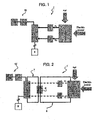
- FIG. 1 diagrammatically shows a fuel cell electric power generator 1 for stationary use and of low capacity, which comprises an electrolyzer 2 configured to receive electric power and water and to convert the latter into its two components, hydrogen and oxygen.
- the generator further comprises tanks 3,4 in which the hydrogen and oxygen produced by electrolyzer 2 are stored.
- Generator 1 comprises a fuel cell stack 5 to which, in use, respective flows of hydrogen and oxygen taken from tanks 3,4 are supplied.
- generator 1 comprises means 10 for dissipation of the heat produced by the oxidation reaction which takes place in the fuel cells.
- these dissipation means 10 consist of one or more appropriately arranged fans V1, V2.
- generator 1 when the power generator 1 is activated to fulfill the electric requirements of a load 6, generator 1 consumes the hydrogen and oxygen previously stored in tanks 3,4, which may be recharged by electrolyzer 2, e.g. when the power generator 1 is returned to stand-by condition.
- electrolyzer 2 there is an optimal operating temperature range for electrolyzer 2, as well, which is from about 40 to about 80°C.
- electrolyzer 2 is forced to work at ambient temperature, i.e. much below the optimal temperature range. This significantly reduces its efficiency and the hydrogen and oxygen output to the detriment of electric power consumption spent for electrolysis and with an undesirable increase of the time needed to restore the hydrogen and oxygen content in tanks 3,4 in view of a new intervention of generator 1.
- a fuel cell electric power generator of the type comprising on-site means for generating gas fuel capable of reducing energy wastes and of increasing the overall efficiency of the on-site process of generating reactants and then converting the chemical energy of the reactants themselves into electric power.
- US6660417 suggested equipping a fuel cell electric power generator with a device for transferring the heat developed in the fuel cell when generating electric power to the electrolyzer.
- US6660417 reference is made to a configuration providing for a first period (of three hours), during which the generator is used to generate the electric power to be supplied to the load, and for a second period (of eight hours), during which electric power is supplied to the electrolyzer to generate hydrogen.
- US6660417 further suggests conveying, during the first period, the water heated up by flowing through the cooling circuit of the fuel cell to a storage tank. During the second period, US6660417 suggests to then convey the heated water collected in the storage tank to the electrolyzer.
- the heated water is used to yield heat to the electrolyzer.
- the heated water is instead directly supplied to the electrolyzer and subjected to the electrolysis process.
- the water volume needed to remove the excess heat developed in the fuel cell during the first period is generally very high and that, consequently, a very large tank is needed to store it, to the detriment of the overall compactness of the system.
- a volume of about 86 L of water would be required.
- the system should thus comprise a storage tank adapted to contain a water volume of at least about 90-100 L.
- the fuel cell generator is an electric power source alternative to the main power source (e.g. the electric mains) and, since it is activated under emergency conditions only, it is preferably an auxiliary component which may be conveniently arranged within spaces intended for other activities (production, storage, etc.).
- the design size of the tank is directly dependent on the specific duration of the respective on/off periods of the fuel cell generator and of the electrolyzer. Therefore, such a system is not very suitable for back-up applications, in which the duration of the respective on/off periods of both generator and electrolyzer may not be univocally estimated in advance, and the number of the generator interventions - and thus of the on/off periods - in one day is not intrinsically predictable.
- the design volume of the tank could in fact not be suited to the actual operating conditions.
- afuel cell electric power generator of the type comprising on-site means for generating gas fuel, in particular for back-up applications, which is capable of meeting the energy and management requirements of the aforesaid system, while ensuring the possibility of limiting the overall size of the system and wisely managing the involved heat flows, both during the start-up phase of the various apparatus and during the corresponding full-capacity operating phase.
- the aforesaid object is achieved by the present invention, as it relates to afuel cell electric power generator as defined in claim 1.
- numeral 1 indicates as a whole a fuel cell electric power generator according to the invention.
- Generator 1 comprises a plurality of fuel cells stacked to form a stack 5 fluidically connected to tanks 3,4 from which it receives, in use, respective flows of gas fuel and oxidizing gas, either pure or in gaseous mixture, to produce electric power to be supplied to a load 6.
- Generator 1 futher comprises on-site means 2 for gneerating the gas fuel to be supplied to stack 5.
- the means 2 for generating gas fuel comprise an electrolyzer configured to receive electric power and water and to convert the latter into its two components, hydrogen and oxygen, which are stored in respective tanks 3,4.
- Generator 1 thus uses hydrogen as a gas fuel and oxygen as an oxidizing gas.
- Generator 1 advantageously comprises a hydraulic circuit 7 for cooling stack 5, within which a thermal carrier fluid, e.g. water, is circulated in order to remove at least part of the heat locally developed by the oxidation reaction from stack 5.
- a thermal carrier fluid e.g. water
- generator 1 comprises a hydraulic circuit 8 for heating electrolyzer 2, within which a thermal carrier fluid, e.g. water, is circulated to supply to electrolyzer 2 at least part of the heat needed to maintain the temperature thereof within the optimal operating range.
- generator 1 further advantageously comprises a heat exchanger 9 at which the hydraulic circuits 7, 8 are hydraulically coupled and, therefore, the thermal integration is obtained between stack 5 and electrolyzer 2. In other words, at least part of the excess heat developed within stack 5 by the oxidation reaction is removed and conveniently transferred to electrolyzer 2.
- power generator 1 is a generator devised for back-up applications, i.e. it is activated for meeting the power requirements of load 6 in event of an emergency situation, e.g. a blackout
- the emergency situation is relatively short (e.g. of the order of 10 min)
- the heat amount exchanged by the heat exchanger 9 between hydraulic circuits 7 and 8 also by virtue of the significant thermal capacity of the thermal carrier fluid (water)
- the thermal carrier fluid water
- generator 1 preferably comprises means 10 for dissipation of the heat produced by the oxidation reaction taking place within stack 5, which comprise one or more appropriately arranged fans V1, V2, for example.
- the second dissipation means 10 are activated when the emergency situation, i.e. the period of activity of generator 1, extends over a relatively long time (e.g. a blackout longer than 10 min), so that the excess heat developed within stack 5 by the oxidation reaction is partially dissipated and partially transferred to hydraulic circuit 8, and thus to electrolyzer 2, which is advantageously maintained within the respective optimal operating temperature range.
- the emergency situation i.e. the period of activity of generator 1
- a relatively long time e.g. a blackout longer than 10 min
- Generator 1 preferably comprises a control unit (not shown) programmed to manage the hydraulic circuits 7 and 8, and the heat exchanger 9 so as to maintain the electrolyzer within the optimal operating temperature range.
- the control unit is connected to means for detecting and transmitting a temperature value in stack 5 and electrolyzer 2, and to respective cut-off means of the thermal carrier fluid flows in the hydraulic circuits 7 and 8.
- control unit is programmed to adjust the thermal carrier fluid flows in the hydraulic circuits 7, 8, and therefore the efficiency and amount of heat exchange in the heat exchanger 9 as well, so as to effectively transfer heat from stack 5 to electrolyzer 2 and to maintain the temperature of both within the respective optimal operating temperature ranges.
- control unit is connected to dissipation means 10, which the control unit activates when it detects that the temperature of stack 5 exceeds a predetermined threshold value. Given the involved heat flows, this event generally occurs when the operating period of generator 1, i.e. of stack 5 to produce electric power to be supplied to load 6, is longer than ten minutes (extended blackout).
- generator 1 When generator 1 is activated to supply an electric load, respective flows of hydrogen and oxygen are sent to stack 5 from tanks 3,4.
- the oxidation reaction which occurs in stack 5 develops heat, which is at least partially removed by a flow of thermal carrier fluid circulating within hydraulic circuit 7.
- said heat is yielded to a thermal carrier fluid flow circulating within hydraulic circuit 8, and, in cascade, to electrolyzer 2, which is thus maintained at a temperature within the optimal temperature range for its operation.
- the amount of the heat exchange carried out by the heat exchanger 9 between the hydraulic circuits 7 and 8, also by virtue of the significant thermal capacity of the thermal carrier fluid (water), is substantially sufficient per se to dispose of the excess heat developed within stack 5 by the oxidation reaction, thus maintaining stack 5 within the optimal operating temperature range.
- Such a removed heat is conveniently transferred to electrolyzer 2, which is thus advantageously maintained within the respective optimal operating temperature range.
- second dissipation means 10 are also activated so that the excess heat developed within stack 5 by the oxidation reaction is partially dissipated and partially transferred to hydraulic circuit 8, and thus to electrolyzer 2.
- both stack 5 and electrolyzer 2 are advantageously maintained within respective optimal operating temperature ranges.
- electrolyzer 2 When generator 1 is set to stand-by, e.g. once the blackout which determined its activation to supply the electric load has been finished, electrolyzer 2 is thus at the ideal temperature to be activated to produce hydrogen and oxygen from water, so as to restore the contents of tanks 3,4 in view of the subsequent intervention of generator 1.
- thermal integration and efficiency of generator 1 is greatly improved.
- the amount of thermal power developed in stack 5 by the oxidation reaction is no longer dissipated, unless partially when the activity period of generator 1 extends beyond a threshold time (e.g. of the order of 10 min), but is advantageously recovered to be used within the generator 2 itself, and more particularly transferred to electrolyzer 2.
- electrolyzer 2 At the end of the emergency situation, i.e. when the activity of stack 5 is interrupted whereas electrolyzer 2 is started to restore the contents in tank 3,4, electrolyzer 2 will immediately operate under conditions which correspond to maximum efficiency and output, thus eliminating the low efficiency transient associated with the above-described traditional configuration.
- the overall efficiency of the whole generation/consumption process of the reactants is advantageously increased because, by increasing the degree of thermal integration, energy wastes are reduced and because operation under maximum efficiency conditions of the most delicate components of generator 1 is promoted.
- dissipation means 10 no longer need to be activated since the amount of the heat exchange carried out at the heat exchanger 9 is sufficient to dispose of the excess heat developed within stack 5, thus obtaining an important reduction of consumptions related to the auxiliary components of generator 1, and at the same time a considerable reduction of noise and wear of the components themselves.
- temperature control is more effective and accurate because the temperature of stack 5 is controlled by removing heat by means of a thermal carrier fluid, in particular when a thermal carrier fluid with a high thermal inertia, such as water, is used.
- generator 1 may be easily limited, while ensuring a satisfactory management of heat exchanges in the process, because the thermal coupling between stack 5 and electrolyzer 2 is carried out by means of two different circuits 7 and 8, and without interposing a thermal carrier fluid storage tank.
- generator 1 The possibility of limiting the overall size of generator 1 ensured by the invention is also advantageous in prospect of further integrating, within a single system, generator 1 with other possible auxiliary components, as more space is made available for their introduction. Moreover, if the auxiliary components are to be cooled as well, the thermal integration ensured by generator 1 according to the invention may also be advantageous from the point of view of an integrated management of the overall heat dissipation.
Landscapes
- Life Sciences & Earth Sciences (AREA)
- Engineering & Computer Science (AREA)
- Sustainable Development (AREA)
- Sustainable Energy (AREA)
- Chemical & Material Sciences (AREA)
- Chemical Kinetics & Catalysis (AREA)
- Electrochemistry (AREA)
- General Chemical & Material Sciences (AREA)
- Manufacturing & Machinery (AREA)
- Electrolytic Production Of Non-Metals, Compounds, Apparatuses Therefor (AREA)
- Fuel Cell (AREA)
- Hydrogen, Water And Hydrids (AREA)
Description
- The present invention relates to a fuel cell electric power generator and to a management method thereof.
- Fuel cell electric power generators (UPS) for stationary use and having low capacity (5-20 kW) based on the use of PEM-type (Proton Exchange Membrane) fuel cells, in which hydrogen is used as a fuel, are generally designed for back-up applications. In other words, these systems work in a nearly constant state of operative "lethargy" (stand-by state) but should be readily activated in a very short time, under safe and reliable conditions, to ensure that the electric power requirements of the load be met in case of emergency.
- As the extended and/or frequent use of these generators is not required, at least in principle, installing complex systems for the storage and supply of hydrogen , such as liquid hydrogen evaporation systems, in which hydrogen is stored at cryogenic temperatures, is not cost-effective.
- Furthermore, the simplest systems for storage and supply most frequently used in the field, in which hydrogen is taken from sets of highly pressurized gas cylinders, originate safety problems which are often underestimated, and which concern their installation, management and maintenance.
- In order to obviate these drawbacks, the operative practice of structurally connecting and functionally coupling the stack of fuel cells of an electric power generator to on-site means for generating gaseous fuel has caught on in the field. In particular, where the cells use hydrogen as a fuel, fuel cell electric power generators comprising an electrolyzer for producing hydrogen are known. A typical configuration of such an electric power generator is shown in
Figure 1 . -
Figure 1 diagrammatically shows a fuel cell electric power generator 1 for stationary use and of low capacity, which comprises an electrolyzer 2 configured to receive electric power and water and to convert the latter into its two components, hydrogen and oxygen. The generator further comprises tanks 3,4 in which the hydrogen and oxygen produced by electrolyzer 2 are stored. Generator 1 comprises a fuel cell stack 5 to which, in use, respective flows of hydrogen and oxygen taken from tanks 3,4 are supplied. - Since the fuel cells stacked to form stack 5 need to work within an optimal temperature range for their correct operation, stack 5 is preferably maintained in use at a substantially constant temperature (generally within a range from 40 to 80°C). For this purpose, generator 1 comprises means 10 for dissipation of the heat produced by the oxidation reaction which takes place in the fuel cells. Typically, these dissipation means 10 consist of one or more appropriately arranged fans V1, V2.
- Hence, when the power generator 1 is activated to fulfill the electric requirements of a
load 6, generator 1 consumes the hydrogen and oxygen previously stored in tanks 3,4, which may be recharged by electrolyzer 2, e.g. when the power generator 1 is returned to stand-by condition. - There is an optimal operating temperature range for electrolyzer 2, as well, which is from about 40 to about 80°C. However, at start-up, and therefore during the first minutes of operation, electrolyzer 2 is forced to work at ambient temperature, i.e. much below the optimal temperature range. This significantly reduces its efficiency and the hydrogen and oxygen output to the detriment of electric power consumption spent for electrolysis and with an undesirable increase of the time needed to restore the hydrogen and oxygen content in tanks 3,4 in view of a new intervention of generator 1.
- Therefore, in the art, there is the need to provide a fuel cell electric power generator, of the type comprising on-site means for generating gaseous fuel, which makes it possible to optimize the operating conditions of said means, especially in the phase of cold start-up thereof.
- In the field, there is the further need to provide a fuel cell electric power generator of the type comprising on-site means for generating gas fuel capable of reducing energy wastes and of increasing the overall efficiency of the on-site process of generating reactants and then converting the chemical energy of the reactants themselves into electric power.
- For example,
US6660417 suggested equipping a fuel cell electric power generator with a device for transferring the heat developed in the fuel cell when generating electric power to the electrolyzer. - More particularly, in
US6660417 reference is made to a configuration providing for a first period (of three hours), during which the generator is used to generate the electric power to be supplied to the load, and for a second period (of eight hours), during which electric power is supplied to the electrolyzer to generate hydrogen. -
- More particularly, in a first embodiment, the heated water is used to yield heat to the electrolyzer. In a second embodiment, the heated water is instead directly supplied to the electrolyzer and subjected to the electrolysis process.
- However, the solution of
US6660417 has some drawbacks. - Firstly, it should be noted that the water volume needed to remove the excess heat developed in the fuel cell during the first period is generally very high and that, consequently, a very large tank is needed to store it, to the detriment of the overall compactness of the system. For example, for disposing an excess heat of the order of 1 kW for 3 h, assuming that water is taken from 25 to 55°C, a volume of about 86 L of water would be required. The system should thus comprise a storage tank adapted to contain a water volume of at least about 90-100 L.
- This aspect is particularly, undesirable, especially for back-up applications in which the fuel cell generator is an electric power source alternative to the main power source (e.g. the electric mains) and, since it is activated under emergency conditions only, it is preferably an auxiliary component which may be conveniently arranged within spaces intended for other activities (production, storage, etc.).
- Furthermore, the design size of the tank is directly dependent on the specific duration of the respective on/off periods of the fuel cell generator and of the electrolyzer. Therefore, such a system is not very suitable for back-up applications, in which the duration of the respective on/off periods of both generator and electrolyzer may not be univocally estimated in advance, and the number of the generator interventions - and thus of the on/off periods - in one day is not intrinsically predictable. The design volume of the tank could in fact not be suited to the actual operating conditions.
- Furthermore, it is worth noting that, as suggested by
US6660417 , during the operation of the fuel cell, a considerable amount of heat is accumulated in the system, which heat is not substantially dissipated or yielded until the next period of activation of the electrolyzer. This circumstance is particularly undesirable for compact systems which, in addition to the power generator, comprise further components which need to be continuously cooled (e.g. electronic components of the control system, etc.). As a matter of fact, the presence of such a large amount of heat stored in the system makes the effective dissipation of other locally produced heat flows particularly difficult. - Finally, it is worth considering that the electrolysis process is theoretically endothermic if conducted under conditions of reversibility. In particular, the need to supply heat to the electrolyzer is concrete and significant during the relative start-up phase. However, because of the usually high degree of irreversibility of the real process - in turn subject to polarization phenomena - in practice, a circumstance generally occurs wherein the electrolyzer should continuously yield heat to the environment in order to be maintained at the required full-capacity operating temperature. The configuration suggested by
US6660417 would instead impose to transfer heat to the electrolyzer during the whole duration of the corresponding working period. - It is thus the object of the present invention to provide an fuel cell electric power generator of the type comprising on-site means for generating gaseous fuel, which makes it possible to simply and cost-effectively overcome the drawbacks associated with the known solutions.
- In particular, it is the object of the present invention to provide afuel cell electric power generator of the type comprising on-site means for generating gas fuel, in particular for back-up applications, which is capable of meeting the energy and management requirements of the aforesaid system, while ensuring the possibility of limiting the overall size of the system and wisely managing the involved heat flows, both during the start-up phase of the various apparatus and during the corresponding full-capacity operating phase. These phases are indeed characterized by reciprocally different process conditions and needs due to their nature.
- The aforesaid object is achieved by the present invention, as it relates to afuel cell electric power generator as defined in claim 1.
- For a better understanding of the present invention, a preferred embodiment will now be described below only by way of non-limitative examples, and with reference to the accompanying drawings, in which:
-
figure 1 diagrammatically shows afuel cell electric power generator according to the prior art; and -
figure 2 diagrammatically shows afuel cell electric power generator according to the invention. - In
figure 2 , numeral 1 indicates as a whole a fuel cell electric power generator according to the invention. - Generator 1 comprises a plurality of fuel cells stacked to form a stack 5 fluidically connected to tanks 3,4 from which it receives, in use, respective flows of gas fuel and oxidizing gas, either pure or in gaseous mixture, to produce electric power to be supplied to a
load 6. - Generator 1 futher comprises on-site means 2 for gneerating the gas fuel to be supplied to stack 5.
- In the illustrated case, the means 2 for generating gas fuel comprise an electrolyzer configured to receive electric power and water and to convert the latter into its two components, hydrogen and oxygen, which are stored in respective tanks 3,4. Generator 1 thus uses hydrogen as a gas fuel and oxygen as an oxidizing gas.
- Generator 1 advantageously comprises a
hydraulic circuit 7 for cooling stack 5, within which a thermal carrier fluid, e.g. water, is circulated in order to remove at least part of the heat locally developed by the oxidation reaction from stack 5. - Moreover, generator 1 comprises a hydraulic circuit 8 for heating electrolyzer 2, within which a thermal carrier fluid, e.g. water, is circulated to supply to electrolyzer 2 at least part of the heat needed to maintain the temperature thereof within the optimal operating range. For this purpose, generator 1 further advantageously comprises a heat exchanger 9 at which the
hydraulic circuits 7, 8 are hydraulically coupled and, therefore, the thermal integration is obtained between stack 5 and electrolyzer 2. In other words, at least part of the excess heat developed within stack 5 by the oxidation reaction is removed and conveniently transferred to electrolyzer 2. - More particularly, if power generator 1 is a generator devised for back-up applications, i.e. it is activated for meeting the power requirements of
load 6 in event of an emergency situation, e.g. a blackout, if the emergency situation is relatively short (e.g. of the order of 10 min), the heat amount exchanged by the heat exchanger 9 betweenhydraulic circuits 7 and 8, also by virtue of the significant thermal capacity of the thermal carrier fluid (water), is substantially sufficient to dispose of the excess heat developed within stack 5 by the oxidation reaction, i.e. to maintain stack 5 within the optimal operating temperature range. Said removed heat is conveniently transferred to electrolyzer 2, which is thus advantageously maintained within the respective optimal operating temperature range. - Moreover, generator 1 preferably comprises means 10 for dissipation of the heat produced by the oxidation reaction taking place within stack 5, which comprise one or more appropriately arranged fans V1, V2, for example.
- In particular, the second dissipation means 10 are activated when the emergency situation, i.e. the period of activity of generator 1, extends over a relatively long time (e.g. a blackout longer than 10 min), so that the excess heat developed within stack 5 by the oxidation reaction is partially dissipated and partially transferred to hydraulic circuit 8, and thus to electrolyzer 2, which is advantageously maintained within the respective optimal operating temperature range.
- Generator 1 preferably comprises a control unit (not shown) programmed to manage the
hydraulic circuits 7 and 8, and the heat exchanger 9 so as to maintain the electrolyzer within the optimal operating temperature range. In particular, the control unit is connected to means for detecting and transmitting a temperature value in stack 5 and electrolyzer 2, and to respective cut-off means of the thermal carrier fluid flows in thehydraulic circuits 7 and 8. - More particularly, the control unit is programmed to adjust the thermal carrier fluid flows in the
hydraulic circuits 7, 8, and therefore the efficiency and amount of heat exchange in the heat exchanger 9 as well, so as to effectively transfer heat from stack 5 to electrolyzer 2 and to maintain the temperature of both within the respective optimal operating temperature ranges. - Furthermore, the control unit is connected to dissipation means 10, which the control unit activates when it detects that the temperature of stack 5 exceeds a predetermined threshold value. Given the involved heat flows, this event generally occurs when the operating period of generator 1, i.e. of stack 5 to produce electric power to be supplied to load 6, is longer than ten minutes (extended blackout).
- In use, when generator 1 is activated to supply an electric load, respective flows of hydrogen and oxygen are sent to stack 5 from tanks 3,4. The oxidation reaction which occurs in stack 5 develops heat, which is at least partially removed by a flow of thermal carrier fluid circulating within
hydraulic circuit 7. At the heat exchanger 9, said heat is yielded to a thermal carrier fluid flow circulating within hydraulic circuit 8, and, in cascade, to electrolyzer 2, which is thus maintained at a temperature within the optimal temperature range for its operation. - In case of a relatively short activity period of generator 1 (i.e. of stack 5) in producing electric power (e.g. of the order of 10 min), the amount of the heat exchange carried out by the heat exchanger 9 between the
hydraulic circuits 7 and 8, also by virtue of the significant thermal capacity of the thermal carrier fluid (water), is substantially sufficient per se to dispose of the excess heat developed within stack 5 by the oxidation reaction, thus maintaining stack 5 within the optimal operating temperature range. Such a removed heat is conveniently transferred to electrolyzer 2, which is thus advantageously maintained within the respective optimal operating temperature range. - In case of extended activity of generator 1 (of stack 5) to produce electric power, second dissipation means 10 are also activated so that the excess heat developed within stack 5 by the oxidation reaction is partially dissipated and partially transferred to hydraulic circuit 8, and thus to electrolyzer 2. Thereby, both stack 5 and electrolyzer 2 are advantageously maintained within respective optimal operating temperature ranges.
- When generator 1 is set to stand-by, e.g. once the blackout which determined its activation to supply the electric load has been finished, electrolyzer 2 is thus at the ideal temperature to be activated to produce hydrogen and oxygen from water, so as to restore the contents of tanks 3,4 in view of the subsequent intervention of generator 1.
- Thereby, thermal integration and efficiency of generator 1 is greatly improved. In particular, the amount of thermal power developed in stack 5 by the oxidation reaction is no longer dissipated, unless partially when the activity period of generator 1 extends beyond a threshold time (e.g. of the order of 10 min), but is advantageously recovered to be used within the generator 2 itself, and more particularly transferred to electrolyzer 2.
- Accordingly, the most efficient thermal integration of the system is combined to the advantage of maintaining the electrolyzer 2 within the optimal operating temperature range.
- At the end of the emergency situation, i.e. when the activity of stack 5 is interrupted whereas electrolyzer 2 is started to restore the contents in tank 3,4, electrolyzer 2 will immediately operate under conditions which correspond to maximum efficiency and output, thus eliminating the low efficiency transient associated with the above-described traditional configuration.
- The overall efficiency of the whole generation/consumption process of the reactants is advantageously increased because, by increasing the degree of thermal integration, energy wastes are reduced and because operation under maximum efficiency conditions of the most delicate components of generator 1 is promoted.
- Furthermore, at least when the activity period of the generator does not extend beyond a given threshold time, dissipation means 10 no longer need to be activated since the amount of the heat exchange carried out at the heat exchanger 9 is sufficient to dispose of the excess heat developed within stack 5, thus obtaining an important reduction of consumptions related to the auxiliary components of generator 1, and at the same time a considerable reduction of noise and wear of the components themselves.
- Advantageously, temperature control is more effective and accurate because the temperature of stack 5 is controlled by removing heat by means of a thermal carrier fluid, in particular when a thermal carrier fluid with a high thermal inertia, such as water, is used.
- Furthermore, the overall size and volume of generator 1 may be easily limited, while ensuring a satisfactory management of heat exchanges in the process, because the thermal coupling between stack 5 and electrolyzer 2 is carried out by means of two
different circuits 7 and 8, and without interposing a thermal carrier fluid storage tank. - The possibility of limiting the overall size of generator 1 ensured by the invention is also advantageous in prospect of further integrating, within a single system, generator 1 with other possible auxiliary components, as more space is made available for their introduction. Moreover, if the auxiliary components are to be cooled as well, the thermal integration ensured by generator 1 according to the invention may also be advantageous from the point of view of an integrated management of the overall heat dissipation.
- It is finally apparent that changes and variations may be made to the system described and illustrated herein, without departing from the scope of protection of the appended claims.
Claims (8)
- An electric power generator (1) comprising a plurality of fuel cells stacked in a stack (5) and configured to supply an electric load (6), the generator (1) comprising means (2) for generating a gas fuel to be supplied to the stack (5), and means (7, 10) for removing at least part of a heat flow generated in the stack (5) as a consequence of the consumption of said gas fuel; the generator (1) comprising heating means (8, 9) configured to maintain said means (2) for generating gas fuel in a predetermined temperature range and comprising means (9) for transferring at least part of said removed part of the heat flow generated in the stack (5) from said removing means (7) to said means (2) for generating gas fuel; characterized in that said means (7) for removing at least part of said heat flow generated in the stack (5) comprise a first hydraulic circuit thermally coupled to the stack (5) through which a flow of a first thermal carrier fluid passes and in that said heating means (8,9) comprise a second hydraulic circuit (8) thermally coupled to the means (2) for generating gas fuel and through which a flow of a second thermal carrier fluid passes.
- The generator according to claim 1, wherein the means (9) for transferring at least part of said removed part of the heat flow generated in the stack (5) comprise a heat exchanger.
- The generator according to claim 1 or 2, wherein the gas fuel is hydrogen and the means (2) for generating gas fuel comprise an electrolyzer configured to receive water and electric power and generate hydrogen and oxygen.
- The generator according to any of claims 1 to 3, wherein the means (7, 10) for removing at least part of a heat flow generated in the stack (5) comprise thermal dissipation means (10).
- The generator according to any of claims 1 to 4, comprising a control unit programmed to manage the removing means (7, 10) and the heating means (8, 9) so as to maintain the means (2) for generating gas fuel within said predetermined temperature range.
- A method for managing an electric power generator having fuel cells stacked in a stack (5) and configured to supply an electric load (6), the generator comprising means (2) for generating a gas fuel to be supplied to the stack (5), and means (7, 10) for removing at least part of a heat flow generated in the stack (5) as a consequence of the consumption of said gas fuel; the method comprising the steps of:a) supplying the stack (5) with a flow of gas fuel to generate the electric power required by the electric load (6);b) removing at least part of the heat flow generated by the stack (5) as a consequence of the consumption of said gas fuel by means of a first flow of thermal carrier fluid;c) by means of a second flow of thermal carrier fluid, transferring at least part of said removed part of heat flow generated in the stack (5) to said means (2) for generating gas fuel, so as to maintain the same within a predetermined temperature range, said first and second flows of thermal carrier fluid being thermally coupled and materially separate.
- The method according to claim 6, comprising the step of generating said gas fuel by means of an electrolytic process carried out in said means (2), wherein said predetermined temperature range is from 40 to 80°C.
- The method according to any of claims 6 or 7, comprising the step of maintaining said stack (5) at a temperature from 40 to 80°C.
Priority Applications (4)
| Application Number | Priority Date | Filing Date | Title |
|---|---|---|---|
| SI201130498T SI2548250T1 (en) | 2010-03-15 | 2011-03-15 | Fuel cell electric power generator and management method thereof |
| PL11723609T PL2548250T3 (en) | 2010-03-15 | 2011-03-15 | Fuel cell electric power generator and management method thereof |
| HRP20150494TT HRP20150494T1 (en) | 2010-03-15 | 2011-03-15 | ELECTRICITY GENERATOR WITH FUEL CELLS AND MANAGEMENT PROCEDURE |
| CY20151100427T CY1116524T1 (en) | 2010-03-15 | 2015-05-14 | ELECTRIC POWER FUEL CAPACITY GENERATION AND MANAGEMENT METHOD |
Applications Claiming Priority (2)
| Application Number | Priority Date | Filing Date | Title |
|---|---|---|---|
| IT000192A ITTO20100192A1 (en) | 2010-03-15 | 2010-03-15 | ELECTRIC POWER FUEL CELL GENERATOR AND RELATED MANAGEMENT METHOD |
| PCT/IB2011/000544 WO2011114215A2 (en) | 2010-03-15 | 2011-03-15 | Fuel cell electric power generator and management method thereof |
Publications (2)
| Publication Number | Publication Date |
|---|---|
| EP2548250A2 EP2548250A2 (en) | 2013-01-23 |
| EP2548250B1 true EP2548250B1 (en) | 2015-02-25 |
Family
ID=43086481
Family Applications (1)
| Application Number | Title | Priority Date | Filing Date |
|---|---|---|---|
| EP11723609.1A Active EP2548250B1 (en) | 2010-03-15 | 2011-03-15 | Fuel cell electric power generator and management method thereof |
Country Status (18)
| Country | Link |
|---|---|
| US (1) | US20130059218A1 (en) |
| EP (1) | EP2548250B1 (en) |
| JP (1) | JP2013522836A (en) |
| CN (1) | CN102859773B (en) |
| CA (1) | CA2792731C (en) |
| CY (1) | CY1116524T1 (en) |
| DK (1) | DK2548250T3 (en) |
| ES (1) | ES2536961T3 (en) |
| HR (1) | HRP20150494T1 (en) |
| HU (1) | HUE025020T2 (en) |
| IT (1) | ITTO20100192A1 (en) |
| PL (1) | PL2548250T3 (en) |
| PT (1) | PT2548250E (en) |
| RS (1) | RS54016B1 (en) |
| RU (1) | RU2584248C2 (en) |
| SI (1) | SI2548250T1 (en) |
| SM (1) | SMT201500116B (en) |
| WO (1) | WO2011114215A2 (en) |
Family Cites Families (8)
| Publication number | Priority date | Publication date | Assignee | Title |
|---|---|---|---|---|
| JP2001126742A (en) * | 1999-10-27 | 2001-05-11 | Sanyo Electric Co Ltd | Fuel cell generator |
| US6833207B2 (en) * | 2001-11-09 | 2004-12-21 | Hydrogenics Corporation | Unitized regenerative fuel cell with bifunctional fuel cell humidifier and water electrolyzer |
| US20030196893A1 (en) * | 2002-04-23 | 2003-10-23 | Mcelroy James Frederick | High-temperature low-hydration ion exchange membrane electrochemical cell |
| GB2396688B (en) * | 2002-11-22 | 2006-06-28 | Intelligent Energy Ltd | Thermal energy management in electrochemical fuel cells |
| US7169493B2 (en) * | 2003-04-30 | 2007-01-30 | Proton Energy Systems, Inc. | Fuel cell system with thermal management and method of operation thereof |
| RU2379794C1 (en) * | 2005-12-12 | 2010-01-20 | Тойота Дзидося Кабусики Кайся | Fuel element cooling system and method |
| AT503293B1 (en) * | 2006-05-05 | 2007-09-15 | Fronius Int Gmbh | Cooling system for fuel cell, has pump for delivering coolant and provision is made for de-ionizing resin to arrange in container in interior of equalization container |
| JP2008177100A (en) * | 2007-01-19 | 2008-07-31 | Toyota Motor Corp | Fuel cell system |
-
2010
- 2010-03-15 IT IT000192A patent/ITTO20100192A1/en unknown
-
2011
- 2011-03-15 RU RU2012143724/07A patent/RU2584248C2/en active
- 2011-03-15 PL PL11723609T patent/PL2548250T3/en unknown
- 2011-03-15 JP JP2012557619A patent/JP2013522836A/en not_active Withdrawn
- 2011-03-15 DK DK11723609.1T patent/DK2548250T3/en active
- 2011-03-15 HU HUE11723609A patent/HUE025020T2/en unknown
- 2011-03-15 US US13/634,563 patent/US20130059218A1/en not_active Abandoned
- 2011-03-15 HR HRP20150494TT patent/HRP20150494T1/en unknown
- 2011-03-15 EP EP11723609.1A patent/EP2548250B1/en active Active
- 2011-03-15 ES ES11723609.1T patent/ES2536961T3/en active Active
- 2011-03-15 RS RS20150336A patent/RS54016B1/en unknown
- 2011-03-15 WO PCT/IB2011/000544 patent/WO2011114215A2/en not_active Ceased
- 2011-03-15 CN CN201180014298.6A patent/CN102859773B/en active Active
- 2011-03-15 SI SI201130498T patent/SI2548250T1/en unknown
- 2011-03-15 CA CA2792731A patent/CA2792731C/en active Active
- 2011-03-15 PT PT117236091T patent/PT2548250E/en unknown
-
2015
- 2015-05-14 CY CY20151100427T patent/CY1116524T1/en unknown
- 2015-05-15 SM SM201500116T patent/SMT201500116B/en unknown
Also Published As
| Publication number | Publication date |
|---|---|
| PT2548250E (en) | 2015-06-09 |
| WO2011114215A2 (en) | 2011-09-22 |
| SMT201500116B (en) | 2015-07-09 |
| HUE025020T2 (en) | 2016-04-28 |
| WO2011114215A3 (en) | 2011-12-01 |
| US20130059218A1 (en) | 2013-03-07 |
| ITTO20100192A1 (en) | 2011-09-16 |
| CY1116524T1 (en) | 2017-03-15 |
| CA2792731C (en) | 2017-09-19 |
| CN102859773A (en) | 2013-01-02 |
| RS54016B1 (en) | 2015-10-30 |
| ES2536961T3 (en) | 2015-06-01 |
| HRP20150494T1 (en) | 2015-06-19 |
| RU2584248C2 (en) | 2016-05-20 |
| SI2548250T1 (en) | 2015-10-30 |
| JP2013522836A (en) | 2013-06-13 |
| CN102859773B (en) | 2015-07-08 |
| EP2548250A2 (en) | 2013-01-23 |
| RU2012143724A (en) | 2014-04-20 |
| PL2548250T3 (en) | 2015-08-31 |
| CA2792731A1 (en) | 2011-09-22 |
| DK2548250T3 (en) | 2015-05-11 |
Similar Documents
| Publication | Publication Date | Title |
|---|---|---|
| Mermelstein et al. | Development and demonstration of a novel reversible SOFC system for utility and micro grid energy storage | |
| US7381313B2 (en) | Integrated hydrogen production and processing system and method of operation | |
| JP5908457B2 (en) | Equipment for electrical energy storage and restoration | |
| US9509026B2 (en) | Power station arrangement with high-temperature storage unit | |
| CN106299412B (en) | Thermal control system and application in a kind of hydrogen energy-storage system | |
| US20110283701A1 (en) | Self Powered Cooling | |
| EP3358167A1 (en) | Compressed air storage power generating device and compressed air storage power generation method | |
| KR101531291B1 (en) | high-brid cogeneration system | |
| KR20130114136A (en) | Integrated cooling system | |
| BR0316454B1 (en) | fuel cell assembly, and method to operate the same. | |
| RU2371813C1 (en) | Autonomous power supply system and method of its operation | |
| JP2019133803A (en) | Power supply system and hydrogen utilization system | |
| CA2792731C (en) | Fuel cell system with multiple cooling circuits | |
| US10026982B2 (en) | Condensate recovery for reversible solid oxide fuel cells | |
| SU1537978A1 (en) | Plant for solar and geothermal central heat supply | |
| JP2013541148A (en) | Method and apparatus for preventing oxidation of anode | |
| JP2013057435A (en) | Heat supply system | |
| JP2013015244A (en) | System and method for preventing and controlling freeze of piping | |
| JP2019189511A (en) | Hydrogen storage system and hydrogen storage method | |
| CN222809555U (en) | Thermal management system, hydrogen production and energy storage system and new energy hydrogen production and energy storage system | |
| EP1233467A2 (en) | Method and device for mutually cooling and preheating of coupled electrochemical transducers | |
| JP2010021061A (en) | Fuel cell power generation system | |
| AU2024349761A1 (en) | Offshore electrolysis system, and method for operating an offshore electrolysis system | |
| US20180069250A1 (en) | Fuel cell system and its operation method | |
| CN120813730A (en) | Energy recovery system and related method for recovering energy |
Legal Events
| Date | Code | Title | Description |
|---|---|---|---|
| PUAI | Public reference made under article 153(3) epc to a published international application that has entered the european phase |
Free format text: ORIGINAL CODE: 0009012 |
|
| 17P | Request for examination filed |
Effective date: 20120913 |
|
| AK | Designated contracting states |
Kind code of ref document: A2 Designated state(s): AL AT BE BG CH CY CZ DE DK EE ES FI FR GB GR HR HU IE IS IT LI LT LU LV MC MK MT NL NO PL PT RO RS SE SI SK SM TR |
|
| DAX | Request for extension of the european patent (deleted) | ||
| RIC1 | Information provided on ipc code assigned before grant |
Ipc: H01M 8/06 20060101ALI20131217BHEP Ipc: H01M 16/00 20060101ALI20131217BHEP Ipc: H01M 8/04 20060101AFI20131217BHEP |
|
| GRAP | Despatch of communication of intention to grant a patent |
Free format text: ORIGINAL CODE: EPIDOSNIGR1 |
|
| INTG | Intention to grant announced |
Effective date: 20140303 |
|
| GRAS | Grant fee paid |
Free format text: ORIGINAL CODE: EPIDOSNIGR3 |
|
| GRAA | (expected) grant |
Free format text: ORIGINAL CODE: 0009210 |
|
| AK | Designated contracting states |
Kind code of ref document: B1 Designated state(s): AL AT BE BG CH CY CZ DE DK EE ES FI FR GB GR HR HU IE IS IT LI LT LU LV MC MK MT NL NO PL PT RO RS SE SI SK SM TR |
|
| REG | Reference to a national code |
Ref country code: GB Ref legal event code: FG4D |
|
| REG | Reference to a national code |
Ref country code: CH Ref legal event code: EP |
|
| REG | Reference to a national code |
Ref country code: IE Ref legal event code: FG4D |
|
| REG | Reference to a national code |
Ref country code: DE Ref legal event code: R096 Ref document number: 602011013994 Country of ref document: DE Effective date: 20150409 |
|
| REG | Reference to a national code |
Ref country code: AT Ref legal event code: REF Ref document number: 712671 Country of ref document: AT Kind code of ref document: T Effective date: 20150415 |
|
| REG | Reference to a national code |
Ref country code: FR Ref legal event code: PLFP Year of fee payment: 5 |
|
| REG | Reference to a national code |
Ref country code: HR Ref legal event code: TUEP Ref document number: P20150494 Country of ref document: HR Ref country code: DK Ref legal event code: T3 Effective date: 20150507 |
|
| REG | Reference to a national code |
Ref country code: RO Ref legal event code: EPE |
|
| REG | Reference to a national code |
Ref country code: ES Ref legal event code: FG2A Ref document number: 2536961 Country of ref document: ES Kind code of ref document: T3 Effective date: 20150601 |
|
| REG | Reference to a national code |
Ref country code: PT Ref legal event code: SC4A Free format text: AVAILABILITY OF NATIONAL TRANSLATION Effective date: 20150514 |
|
| REG | Reference to a national code |
Ref country code: SE Ref legal event code: TRGR |
|
| REG | Reference to a national code |
Ref country code: NL Ref legal event code: T3 |
|
| REG | Reference to a national code |
Ref country code: HR Ref legal event code: T1PR Ref document number: P20150494 Country of ref document: HR |
|
| REG | Reference to a national code |
Ref country code: NO Ref legal event code: T2 Effective date: 20150225 |
|
| REG | Reference to a national code |
Ref country code: EE Ref legal event code: FG4A Ref document number: E010630 Country of ref document: EE Effective date: 20150512 |
|
| REG | Reference to a national code |
Ref country code: GR Ref legal event code: EP Ref document number: 20150401041 Country of ref document: GR Effective date: 20150618 |
|
| REG | Reference to a national code |
Ref country code: SK Ref legal event code: T3 Ref document number: E 18609 Country of ref document: SK |
|
| REG | Reference to a national code |
Ref country code: PL Ref legal event code: T3 |
|
| PG25 | Lapsed in a contracting state [announced via postgrant information from national office to epo] |
Ref country code: CY Free format text: LAPSE BECAUSE OF NON-PAYMENT OF DUE FEES Effective date: 20150315 |
|
| REG | Reference to a national code |
Ref country code: DE Ref legal event code: R097 Ref document number: 602011013994 Country of ref document: DE |
|
| PLBE | No opposition filed within time limit |
Free format text: ORIGINAL CODE: 0009261 |
|
| STAA | Information on the status of an ep patent application or granted ep patent |
Free format text: STATUS: NO OPPOSITION FILED WITHIN TIME LIMIT |
|
| 26N | No opposition filed |
Effective date: 20151126 |
|
| REG | Reference to a national code |
Ref country code: FR Ref legal event code: PLFP Year of fee payment: 6 |
|
| REG | Reference to a national code |
Ref country code: HU Ref legal event code: AG4A Ref document number: E025020 Country of ref document: HU |
|
| REG | Reference to a national code |
Ref country code: AT Ref legal event code: UEP Ref document number: 712671 Country of ref document: AT Kind code of ref document: T Effective date: 20150225 |
|
| REG | Reference to a national code |
Ref country code: FR Ref legal event code: PLFP Year of fee payment: 7 |
|
| PGFP | Annual fee paid to national office [announced via postgrant information from national office to epo] |
Ref country code: EE Payment date: 20170329 Year of fee payment: 7 Ref country code: LT Payment date: 20170313 Year of fee payment: 7 Ref country code: SE Payment date: 20170327 Year of fee payment: 7 Ref country code: NO Payment date: 20170327 Year of fee payment: 7 Ref country code: CH Payment date: 20170314 Year of fee payment: 7 Ref country code: RO Payment date: 20170313 Year of fee payment: 7 |
|
| PGFP | Annual fee paid to national office [announced via postgrant information from national office to epo] |
Ref country code: RS Payment date: 20170310 Year of fee payment: 7 Ref country code: AT Payment date: 20170327 Year of fee payment: 7 Ref country code: SM Payment date: 20170321 Year of fee payment: 7 Ref country code: LV Payment date: 20170329 Year of fee payment: 7 |
|
| PGFP | Annual fee paid to national office [announced via postgrant information from national office to epo] |
Ref country code: HU Payment date: 20170404 Year of fee payment: 7 |
|
| REG | Reference to a national code |
Ref country code: FR Ref legal event code: PLFP Year of fee payment: 8 |
|
| REG | Reference to a national code |
Ref country code: LT Ref legal event code: MM4D Effective date: 20180315 |
|
| REG | Reference to a national code |
Ref country code: EE Ref legal event code: MM4A Ref document number: E010630 Country of ref document: EE Effective date: 20180331 |
|
| REG | Reference to a national code |
Ref country code: NO Ref legal event code: MMEP |
|
| PG25 | Lapsed in a contracting state [announced via postgrant information from national office to epo] |
Ref country code: SE Free format text: LAPSE BECAUSE OF NON-PAYMENT OF DUE FEES Effective date: 20180316 Ref country code: LT Free format text: LAPSE BECAUSE OF NON-PAYMENT OF DUE FEES Effective date: 20180315 |
|
| PGFP | Annual fee paid to national office [announced via postgrant information from national office to epo] |
Ref country code: AL Payment date: 20160330 Year of fee payment: 6 |
|
| REG | Reference to a national code |
Ref country code: CH Ref legal event code: PL |
|
| REG | Reference to a national code |
Ref country code: AT Ref legal event code: MM01 Ref document number: 712671 Country of ref document: AT Kind code of ref document: T Effective date: 20180315 |
|
| PG25 | Lapsed in a contracting state [announced via postgrant information from national office to epo] |
Ref country code: LV Free format text: LAPSE BECAUSE OF NON-PAYMENT OF DUE FEES Effective date: 20180315 Ref country code: RS Free format text: LAPSE BECAUSE OF NON-PAYMENT OF DUE FEES Effective date: 20180921 |
|
| PG25 | Lapsed in a contracting state [announced via postgrant information from national office to epo] |
Ref country code: RO Free format text: LAPSE BECAUSE OF NON-PAYMENT OF DUE FEES Effective date: 20180315 Ref country code: HU Free format text: LAPSE BECAUSE OF NON-PAYMENT OF DUE FEES Effective date: 20180316 Ref country code: NO Free format text: LAPSE BECAUSE OF NON-PAYMENT OF DUE FEES Effective date: 20180331 Ref country code: EE Free format text: LAPSE BECAUSE OF NON-PAYMENT OF DUE FEES Effective date: 20180331 Ref country code: AT Free format text: LAPSE BECAUSE OF NON-PAYMENT OF DUE FEES Effective date: 20180315 |
|
| REG | Reference to a national code |
Ref country code: HR Ref legal event code: ODRP Ref document number: P20150494 Country of ref document: HR Payment date: 20190214 Year of fee payment: 9 |
|
| PG25 | Lapsed in a contracting state [announced via postgrant information from national office to epo] |
Ref country code: SM Free format text: LAPSE BECAUSE OF NON-PAYMENT OF DUE FEES Effective date: 20181002 Ref country code: CH Free format text: LAPSE BECAUSE OF NON-PAYMENT OF DUE FEES Effective date: 20180331 Ref country code: LI Free format text: LAPSE BECAUSE OF NON-PAYMENT OF DUE FEES Effective date: 20180331 |
|
| PGFP | Annual fee paid to national office [announced via postgrant information from national office to epo] |
Ref country code: CZ Payment date: 20190219 Year of fee payment: 9 |
|
| PGFP | Annual fee paid to national office [announced via postgrant information from national office to epo] |
Ref country code: BG Payment date: 20200330 Year of fee payment: 10 |
|
| REG | Reference to a national code |
Ref country code: HR Ref legal event code: ODRP Ref document number: P20150494 Country of ref document: HR Payment date: 20200421 Year of fee payment: 10 |
|
| PGFP | Annual fee paid to national office [announced via postgrant information from national office to epo] |
Ref country code: LU Payment date: 20200330 Year of fee payment: 10 |
|
| PGFP | Annual fee paid to national office [announced via postgrant information from national office to epo] |
Ref country code: SK Payment date: 20200414 Year of fee payment: 10 |
|
| PGFP | Annual fee paid to national office [announced via postgrant information from national office to epo] |
Ref country code: MK Payment date: 20200409 Year of fee payment: 10 |
|
| PG25 | Lapsed in a contracting state [announced via postgrant information from national office to epo] |
Ref country code: MC Free format text: LAPSE BECAUSE OF NON-PAYMENT OF DUE FEES Effective date: 20200331 Ref country code: CZ Free format text: LAPSE BECAUSE OF NON-PAYMENT OF DUE FEES Effective date: 20200315 |
|
| PG25 | Lapsed in a contracting state [announced via postgrant information from national office to epo] |
Ref country code: AL Free format text: LAPSE BECAUSE OF NON-PAYMENT OF DUE FEES Effective date: 20180315 |
|
| REG | Reference to a national code |
Ref country code: HR Ref legal event code: ODRP Ref document number: P20150494 Country of ref document: HR Payment date: 20210312 Year of fee payment: 11 |
|
| REG | Reference to a national code |
Ref country code: DE Ref legal event code: R081 Ref document number: 602011013994 Country of ref document: DE Owner name: ELECTRO POWER SYSTEMS MANUFACTURING S.R.L., IT Free format text: FORMER OWNER: ELECTRO POWER SYSTEMS S.P.A., TORINO, IT |
|
| REG | Reference to a national code |
Ref country code: FI Ref legal event code: PCE Owner name: ELECTRO POWER SYSTEMS MANUFACTURING S.R.L. |
|
| REG | Reference to a national code |
Ref country code: ES Ref legal event code: PC2A Owner name: ELECTRO POWER SYSTEMS MANUFACTURING S.R.L. Effective date: 20210608 |
|
| REG | Reference to a national code |
Ref country code: BE Ref legal event code: PD Owner name: ELECTRO POWER SYSTEMS MANUFACTURING S.R.L.; IT Free format text: DETAILS ASSIGNMENT: CHANGE OF OWNER(S), CHANGE OF LEGAL ENTITY; FORMER OWNER NAME: ELECTRO POWER SYSTEMS S.P.A. Effective date: 20210429 |
|
| REG | Reference to a national code |
Ref country code: HR Ref legal event code: PNAN Ref document number: P20150494 Country of ref document: HR Owner name: ELECTRO POWER SYSTEMS MANUFACTURING S.R.L., IT |
|
| REG | Reference to a national code |
Ref country code: SI Ref legal event code: SP73 Owner name: ELECTRO POWER SYSTEMS MANUFACTURING S.R.L.; IT Effective date: 20210610 |
|
| REG | Reference to a national code |
Ref country code: NL Ref legal event code: PD Owner name: ELECTRO POWER SYSTEMS MANUFACTURING S.R.L.; IT Free format text: DETAILS ASSIGNMENT: CHANGE OF OWNER(S), CHANGE OF LEGAL ENTITY; FORMER OWNER NAME: ELECTRO POWER SYSTEMS S.P.A. Effective date: 20210720 |
|
| REG | Reference to a national code |
Ref country code: SK Ref legal event code: MM4A Ref document number: E 18609 Country of ref document: SK Effective date: 20210315 |
|
| PG25 | Lapsed in a contracting state [announced via postgrant information from national office to epo] |
Ref country code: SK Free format text: LAPSE BECAUSE OF NON-PAYMENT OF DUE FEES Effective date: 20210315 Ref country code: LU Free format text: LAPSE BECAUSE OF NON-PAYMENT OF DUE FEES Effective date: 20210315 Ref country code: BG Free format text: LAPSE BECAUSE OF NON-PAYMENT OF DUE FEES Effective date: 20210930 |
|
| REG | Reference to a national code |
Ref country code: HR Ref legal event code: ODRP Ref document number: P20150494 Country of ref document: HR Payment date: 20220311 Year of fee payment: 12 |
|
| REG | Reference to a national code |
Ref country code: HR Ref legal event code: ODRP Ref document number: P20150494 Country of ref document: HR Payment date: 20230307 Year of fee payment: 13 |
|
| P01 | Opt-out of the competence of the unified patent court (upc) registered |
Effective date: 20230601 |
|
| REG | Reference to a national code |
Ref country code: HR Ref legal event code: ODRP Ref document number: P20150494 Country of ref document: HR Payment date: 20240308 Year of fee payment: 14 |
|
| REG | Reference to a national code |
Ref country code: HR Ref legal event code: ODRP Ref document number: P20150494 Country of ref document: HR Payment date: 20250312 Year of fee payment: 15 |
|
| PGFP | Annual fee paid to national office [announced via postgrant information from national office to epo] |
Ref country code: ES Payment date: 20250416 Year of fee payment: 15 |
|
| PGFP | Annual fee paid to national office [announced via postgrant information from national office to epo] |
Ref country code: CY Payment date: 20250402 Year of fee payment: 15 |
|
| PGFP | Annual fee paid to national office [announced via postgrant information from national office to epo] |
Ref country code: GB Payment date: 20260324 Year of fee payment: 16 |
|
| REG | Reference to a national code |
Ref country code: HR Ref legal event code: ODRP Ref document number: P20150494 Country of ref document: HR Payment date: 20260306 Year of fee payment: 16 |
|
| PGFP | Annual fee paid to national office [announced via postgrant information from national office to epo] |
Ref country code: DK Payment date: 20260323 Year of fee payment: 16 Ref country code: IE Payment date: 20260323 Year of fee payment: 16 Ref country code: DE Payment date: 20260320 Year of fee payment: 16 |
|
| PGFP | Annual fee paid to national office [announced via postgrant information from national office to epo] |
Ref country code: HR Payment date: 20260306 Year of fee payment: 16 |
|
| PGFP | Annual fee paid to national office [announced via postgrant information from national office to epo] |
Ref country code: BE Payment date: 20260323 Year of fee payment: 16 Ref country code: FI Payment date: 20260320 Year of fee payment: 16 Ref country code: IT Payment date: 20260219 Year of fee payment: 16 |
|
| PGFP | Annual fee paid to national office [announced via postgrant information from national office to epo] |
Ref country code: NL Payment date: 20260323 Year of fee payment: 16 |
|
| PGFP | Annual fee paid to national office [announced via postgrant information from national office to epo] |
Ref country code: IS Payment date: 20260328 Year of fee payment: 16 Ref country code: FR Payment date: 20260324 Year of fee payment: 16 |
|
| PGFP | Annual fee paid to national office [announced via postgrant information from national office to epo] |
Ref country code: TR Payment date: 20260305 Year of fee payment: 16 |
|
| PGFP | Annual fee paid to national office [announced via postgrant information from national office to epo] |
Ref country code: PT Payment date: 20260226 Year of fee payment: 16 |
|
| PGFP | Annual fee paid to national office [announced via postgrant information from national office to epo] |
Ref country code: GR Payment date: 20260319 Year of fee payment: 16 Ref country code: PL Payment date: 20260304 Year of fee payment: 16 Ref country code: MT Payment date: 20260326 Year of fee payment: 16 |
|
| PGFP | Annual fee paid to national office [announced via postgrant information from national office to epo] |
Ref country code: SI Payment date: 20260304 Year of fee payment: 16 |