EP2546831B1 - Noise suppression device - Google Patents
Noise suppression device Download PDFInfo
- Publication number
- EP2546831B1 EP2546831B1 EP10847326.5A EP10847326A EP2546831B1 EP 2546831 B1 EP2546831 B1 EP 2546831B1 EP 10847326 A EP10847326 A EP 10847326A EP 2546831 B1 EP2546831 B1 EP 2546831B1
- Authority
- EP
- European Patent Office
- Prior art keywords
- subband
- noise
- spectrum
- representative
- noise suppression
- Prior art date
- Legal status (The legal status is an assumption and is not a legal conclusion. Google has not performed a legal analysis and makes no representation as to the accuracy of the status listed.)
- Active
Links
Images


Classifications
-
- G—PHYSICS
- G10—MUSICAL INSTRUMENTS; ACOUSTICS
- G10L—SPEECH ANALYSIS OR SYNTHESIS; SPEECH RECOGNITION; SPEECH OR VOICE PROCESSING; SPEECH OR AUDIO CODING OR DECODING
- G10L21/00—Processing of the speech or voice signal to produce another audible or non-audible signal, e.g. visual or tactile, in order to modify its quality or its intelligibility
- G10L21/02—Speech enhancement, e.g. noise reduction or echo cancellation
- G10L21/0208—Noise filtering
- G10L21/0216—Noise filtering characterised by the method used for estimating noise
- G10L2021/02161—Number of inputs available containing the signal or the noise to be suppressed
- G10L2021/02163—Only one microphone
-
- G—PHYSICS
- G10—MUSICAL INSTRUMENTS; ACOUSTICS
- G10L—SPEECH ANALYSIS OR SYNTHESIS; SPEECH RECOGNITION; SPEECH OR VOICE PROCESSING; SPEECH OR AUDIO CODING OR DECODING
- G10L21/00—Processing of the speech or voice signal to produce another audible or non-audible signal, e.g. visual or tactile, in order to modify its quality or its intelligibility
- G10L21/02—Speech enhancement, e.g. noise reduction or echo cancellation
- G10L21/0208—Noise filtering
- G10L21/0216—Noise filtering characterised by the method used for estimating noise
- G10L21/0232—Processing in the frequency domain
-
- G—PHYSICS
- G10—MUSICAL INSTRUMENTS; ACOUSTICS
- G10L—SPEECH ANALYSIS OR SYNTHESIS; SPEECH RECOGNITION; SPEECH OR VOICE PROCESSING; SPEECH OR AUDIO CODING OR DECODING
- G10L25/00—Speech or voice analysis techniques not restricted to a single one of groups G10L15/00 - G10L21/00
- G10L25/78—Detection of presence or absence of voice signals
Definitions
- the present invention relates to a noise suppression device which suppresses a noise carried on a voice signal.
- the proposed algorithm measures the amount of the audible noise in the input noisy speech explicitly by using a psychoacoustic model, and decides an appropriate amount of noise reduction accordingly to achieve good noise level reduction without introducing significant distortion to the clean speech embedded in the input noisy signal.
- the proposed algorithm also mitigates the musical noise problem commonly encountered in conventional speech enhancement algorithms by having the amount of noise reduction adapt to the instantly estimated noise amplitude.
- a noise suppression device carries out a noise suppression process of mainly inputting a signal on a time domain in which a noise is carried on a voice signal as an input signal, converting this input signal into a power spectrum which is a signal on a frequency domain, after that, estimating an average power spectrum of the noise from the power spectrum of the input signal, subtracting the estimated power spectrum of the noise from the power spectrum of the input signal to acquire the power spectrum of the input signal in which the noise is suppressed, and returning the power spectrum to the original signal on a time domain.
- patent reference 1 discloses such a conventional noise suppression device.
- the noise suppression device disclosed by patent reference 1 is based on a technique disclosed by nonpatent reference 1, calculates the average of a plurality of power spectrum components of an input signal at the time of estimation of a noise spectrum and at the time of calculation of an amount of suppression, carries out calculation of the noise spectrum and calculation of an amount of suppression from the single average acquired thereby, and applies the noise spectrum and the amount of suppression to the plurality of power spectrum components.
- Patent reference 1 Japanese Patent No. 4172530 (pp. 8-12 and Fig. 2 )
- Nonpatent reference 1 Y.Ephraim, D.Malah, "Speech Enhancement Using a Minimum Mean-Square Error Short-Time Spectral Amplitude Estimator", IEEE Trans. ASSP, Vol.32, No.6, pp.1109-1121, Dec. 1984
- a conventional noise suppression device needs to carry out a complicated calculation, such as a calculation of a Bessel function for each power spectrum component of the input signal, in performing the amount of suppression for noise suppression, and therefore has a large amount of information to be processed.
- the conventional noise suppression device disclosed by patent reference 1 averages the plurality of spectral components collectively, and calculates the averaged spectral component as a representative spectrum component of each spectral component, thereby reducing the amount of information to be processed.
- a problem with this method is, however, that even if a component having a large amplitude exists in the spectral components (i.e. a component which can be assumed to be a voice component), the voice component is underestimated by averaging the spectral components, and, as a result, the voice signal is suppressed and the suppression of the voice increases, so that the voice degrades in its quality.
- the present invention is made in order to solve this problem, and it is therefore an object of the present invention to provide a noise suppression device which can carry out a high-quality noise suppression with a small amount of information to be processed.
- a noise suppression device including a representative component generating unit for combining a plurality of power spectra into which an input signal is converted by a time-to-frequency converting unit into each group, and for selecting a power spectrum having a larger value from among the plurality of power spectra in each group on a priority basis to define the power spectrum selected thereby as a representative power spectrum, in which a noise suppression amount generating unit calculates an amount of noise suppression by using the representative power spectrum.
- the noise suppression device calculates the amount of noise suppression by using the representative power spectrum, the noise suppression device can reduce the amount of information to be processed. Further, because the noise suppression device uses the power spectrum having a larger value in each group as this representative power spectrum, the noise suppression device prevents a voice component of the input signal from being underestimated at the time of the calculation of the amount of noise suppression. As a result, the noise suppression device does not suppress the voice signal, but can carry out a high-quality noise suppression.
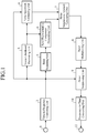
- a noise suppression device shown in Fig. 1 is provided with an input terminal 1, a time-to-frequency converter 2, a voice likelihood estimating unit 3, a noise spectrum estimating unit 4, a band separating unit 5, a band representative component generating unit (representative component generating unit) 6, a noise suppression amount generating unit 7, a band multiple copying unit 8, a noise suppressing unit 9, a frequency-to-time converting unit 10, and an output terminal 11.
- this noise suppression device As an input of this noise suppression device, a signal which is sampled at a predetermined sampling frequency (e.g. 8 kHz) and is divided into frames (each having a duration of 10 ms, for example) after the input is acquired by A/D (analog-to-digital) converting a voice, a musical piece or the like which is captured by way of a microphone (not shown) or the like.
- a predetermined sampling frequency e.g. 8 kHz
- frames each having a duration of 10 ms, for example
- the input terminal 1 accepts such a signal as mentioned above and outputs this signal to the time-to-frequency converting unit 2 as an input signal y(t).
- the time-to-frequency converting unit 2 carries out a process of windowing the input signal y(t) which is divided into frames, and converts the windowed signal y(n, t) on a time axis into a signal (spectrum) on a frequency axis by using, for example, an FFT (Fast Fourier Transform) with 256 points to calculate a power spectrum Y(n, k) and a phase spectrum P(n, k) of the input signal, where n shows a frame number, k shows a spectrum number, and t shows a discrete time number.
- the input signal is the one of the current frame unless otherwise specified, and the frame number will be omitted when the signal shows a spectrum.
- the acquired power spectra are outputted to the voice likelihood estimating unit 3, the noise spectrum estimating unit 4, the band separating unit 5, and the noise suppressing unit 9. Further, the acquired phase spectra are outputted to the frequency-to-time converting unit 10.
- a known method such as a Hanning window or a trapezoidal window, can be used.
- the time-to-frequency converting unit 2 also carries out a zero filling process as needed. Because the FFT is a well-known method, the explanation of this method will be omitted hereafter.
- the voice likelihood estimating unit 3 uses the power spectra of the input signal inputted thereto from the time-to-frequency converting unit 2 to calculate, as a degree of "likelihood that the input signal of the current frame is a voice", a voice likelihood estimated value which has a large value when there is a high likelihood that the input signal is a voice, or has a small value otherwise.
- any one of known methods including a maximum of autocorrelation coefficients acquired by performing a Fourier transform on the power spectra of the input signal, input signal energy acquired from the total sum of the power spectra, an all-band SN ratio (signal to noise ratio) of the input signal, and spectrum entropy showing variations in the power spectra can be used independently, or a combination of some of them can be used.
- a case in which the maximum of the autocorrelation coefficients which can be calculated from the power spectra of the input signal of the current frame is used independently will be shown below.
- the autocorrelation coefficients c( ⁇ ) can be calculated as shown by the following equation (1).
- the voice likelihood estimating unit 3 then normalizes the acquired autocorrelation coefficients c( ⁇ ) so that each of them has a value ranging from 0 to 1 by dividing each of the autocorrelation coefficients by c(0), searches for a maximum of the autocorrelation coefficient in a range of, for example, 16 ⁇ 120 where there is a high possibility that a voice fundamental frequency exists, and outputs the maximum acquired thereby to the noise spectrum estimating unit 4 as a voice likelihood estimated value VAD.
- the noise spectrum estimating unit 4 estimates an average noise spectrum included in the input signal by using both the power spectrum Y(k) of the input signal, and the voice likelihood estimated value VAD. More specifically, the noise spectrum estimating unit 4 refers to the voice likelihood estimated value VAD which is the output of the voice likelihood estimating unit 3, and, when there is a high likelihood that the input signal of the current frame is a noise (i.e. when there is a low likelihood that the input signal of the current frame is a voice), and updates the noise spectrum N(n-1, k) of the immediately preceding frame which the noise spectrum estimating unit 4 has stored by using the power spectrum Y(n, k) of the input signal of the current frame and outputs the noise spectrum updated thereby to the noise suppression amount generating unit 7.
- the noise spectrum estimating unit 4 carries out the update of the noise spectrum by reflecting the power spectrum of the input signal in the noise spectrum according to an equation (2) shown below when the voice likelihood estimated value VAD is equal to or smaller than a predetermined threshold (e.g. 0.2). Because it can be considered that there is a high likelihood that the input signal of the current frame is a voice when the voice likelihood estimated value VAD exceeds the threshold of 0.2, the noise spectrum estimating unit does not carry out the update of the noise spectrum, but uses the noise spectrum of the immediately preceding frame as the noise spectrum of the current frame just as it is.
- a predetermined threshold e.g. 0.2
- n is the frame number
- k is the spectrum number
- K is the value which is half of the number of FFT points
- N(n-1, k) is the noise spectrum yet to be updated
- Y(n, k) is the noise spectrum of the current frame which is determined to have a high likelihood of being a noise
- N ⁇ (n, k) is the noise spectrum updated.
- ⁇ (k) is a predetermined update rate coefficient having a value ranging from 0 to 1, and can be set to a value relatively close to 0.
- ⁇ (k) is a predetermined update rate coefficient having a value ranging from 0 to 1, and can be set to a value relatively close to 0.
- the noise spectrum estimating unit 4 further stores the noise spectrum N(n, k) of the current frame in order to use this noise spectrum in the next update process.
- a storage unit a storage unit which is represented by, for example, a semiconductor memory, a hard disk, or the like, and from and in which data can be read and written electrically or magnetically at any time is used.
- the band separating unit 5 divides the power spectrum Y(k) of the input signal into non-uniform frequency bands to group the power spectrum into subband spectra.
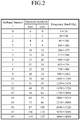
- An example of the division of the band of the power spectrum Y(k) of the input signal is shown in Fig. 2 .
- critical bands 2 are called critical bands, and have a high degree of consistency with human being's aural characteristics .
- the unit of the subband numbers of these critical bands is Bark. Refer to " Psychoacoustics" written by E. Zwicker (Nishimura Co., Ltd., August, 1992 ) for more information on the details of the critical bands.
- Fig. 2 shows the example in which the band separating unit 5 divides the power spectrum into non-uniform frequency subbands existing in the critical bands
- the present embodiment is not limited to this example.
- the band separating unit can carry out division into octave bands whose bandwidths become narrower by a factor of 2 as their frequencies decrease.
- the band separating unit can alternatively carry out division into equal size subbands by which all of the band of the power spectrum is divided into equal size subbands each of which consists of four spectral components.
- the band separating unit can carry out division into finer bands, thereby being able to suppress the degradation of the noise suppression characteristics which will be mentioned below.
- the band separating unit 5 outputs the power spectrum Y(z, k) of the subband number z of each of the subbands into which the band of the power spectrum is grouped to the band representative component generating unit 6 after carrying out the dividing process in the above-mentioned way.
- the band representative component generating unit 6 generates a representative power spectrum Y d (z) representing each subband by using the power spectrum Y(z,k) of each subband inputted thereto from the band separating unit 5, and outputs the representative power spectrum to the noise suppression amount generating unit 7.
- a method of generating the representative power spectrum Y d (z) for example, there is a method, as shown in an equation (3) mentioned below, of sequentially comparing the size of the power spectrum Y(k) with that of another power spectrum within each subband, and defining the power spectrum Y(k) having the largest value as the representative power spectrum Y d (z).
- the voice likelihood estimated value VAD outputted from the voice likelihood estimating unit 3 is equal to or smaller than a predetermined threshold (e.g. 0.2)
- a predetermined threshold e.g. 0.2
- a method, as shown in patent reference 1 of calculating the average of all the power spectra Y(k) within each subband and defining the average as the representative power spectrum Y d (z) is used.
- Y d z ⁇ max Y z k
- Fig. 3 is a view schematically showing the process carried out and an effect provided by the band representative component generating unit 6 according to this Embodiment 1.
- Fig. 3(a) is a graph in which the power spectra of the input signal at a certain time in which a noise is mixed are plotted.
- the vertical axis shows the size (amplitude) of each power spectrum and the horizontal axis shows the frequency.
- each solid line is a power spectrum component of the input signal
- a dashed line shows the envelope of the noise spectrum
- each dashed dotted line shows a boundary between subbands.
- an example in which the frequency band is divided equal size subbands is shown.
- Fig. 3(b) shows results which are acquired in a case of calculating the average of the power spectra in each subband from the input signal shown in Fig. 3 (a) by using a conventional method, and defining the average as the representative power spectrum.
- this method because the size of a power spectrum which is estimated to be a voice component becomes small, the voice component is underestimated by the noise suppression amount generating unit 7 which will be mentioned below, and, as a result, the voice signal is suppressed and the suppression of the voice increases, so that the voice degrades in its quality.
- Fig. 3(c) shows results which are acquired when the band representative component generating unit 6 calculates a representative power spectrum from the input signal shown in Fig. 3(a) .
- the voice likelihood estimated value VAD is sufficiently larger than the threshold of 0.2. Therefore, the band representative component generating unit 6 determines the representative power spectrum according to the above-mentioned equation (3). It can be seen from Fig. 3(c) that as compared with the conventional method shown in Fig. 3(b) , the power spectrum which is estimated to be a voice component is stored, the voice component is not underestimated by the next-stage noise suppression amount generating unit 7, and the voice signal is not suppressed.
- the noise suppression device can switch to the conventional calculating method using the average to generate the representative power spectrum because in another case in which, for example, the voice likelihood estimated value VAD is small and there is a high likelihood that the input signal of the current frame is a noise, there is a high likelihood that even if a power spectrum having a large value exists, the input signal is a noise. Because the noise suppression device can reduce the amplitude of a power spectrum of having a large value which has a high likelihood of being a noise by calculating the average of the power spectra within each subband, the noise suppression device can suppress generation of an erroneous representative power spectrum.
- the band representative component generating unit 6 can always select a method of using, as the representative power spectrum, a power spectrum having a maximum, instead of switching to the method of calculating the representative power spectrum according to the voice likelihood estimated value VAD.
- the noise suppression amount generating unit 7 generates an amount G(z) of noise suppression for each subband by using both the representative power spectrum Y d (z) inputted thereto from the band representative component generating unit 6, and the noise spectrum N(n, k) inputted thereto from the noise spectrum estimating unit 4 according to a predetermined computing equation which is prepared in advance, and outputs the amount G(z) of noise suppression to the band multiple copying unit 8.
- a method of deriving the computing equation for calculating this amount G(z) of noise suppression will be mentioned later.
- the band multiple copying unit 8 generates multiple copies of the amount G(z) of noise suppression for each subband which the noise suppression amount generating unit 7 has acquired for the spectrums belonging to each subband, respectively, to define one of the multiple copies as an amount G(k) of noise suppression for each of the spectrums. More specifically, the band multiple copying unit spreads the amount G(z) of noise suppression for each subband by copying the value of the amount G(z) of noise suppression having a subband number z to the value of the amount G(k) of noise suppression having each spectrum number k belonging to the same subband number z.
- the noise suppression amount generating unit 7 outputs the amount G(k) of noise suppression for each spectrum acquired thereby to the noise suppressing unit 9.
- the noise suppressing unit 9 generates the power spectrum Y ⁇ (k) of the input signal on which a noise suppression has been carried out by using both the power spectrum Y(k) of the input signal inputted thereto from the time-to-frequency converting unit 2, and the amount G(k) of noise suppression for each spectrum inputted thereto from the noise suppression amount generating unit 7 according to an equation (4) shown below, and outputs the power spectrum Y ⁇ (k) of the input signal to the frequency-to-time converting unit 10.
- " ⁇ " (hat symbol) in the above equation (4) is shown by " ⁇ ” because this application is an electronic patent application, and the hat symbol will also be shown by " ⁇ ” in equations shown below.
- the frequency-to-time converting unit 10 converts the spectrum on a frequency domain into a signal on a time domain by performing a reverse fast Fourier transform (reverse FFT) on the spectrum by using both the power spectrum Y ⁇ (k) of the input signal which is inputted thereto from the noise suppressing unit 9 and on which the noise suppression has been carried out, and the phase spectrum P(k) inputted thereto from the time-to-frequency converting unit 2, and, after carrying out an overlapping process of overlapping the signal on a time domain and the signal of the immediately preceding frame which is stored in the frequency-to-time converting unit 10 to generate a signal, outputting this signal to the output terminal 11 as an input signal y ⁇ (t) on which the noise suppression has been carried out.
- the output terminal 11 outputs this input signal y ⁇ (t) on which the noise suppression has been carried out.
- the noise suppression amount generating unit 7 shown in Fig. 4 is provided with a a posteriori SNR (signal to noise ratio) estimating unit 71, a a prior SNR estimating unit 72, a noise suppression amount calculating unit 73, and a delaying unit 74.
- a posteriori SNR signal to noise ratio
- the a posteriori SNR estimating unit 71 estimates a a posteriori SNR ⁇ ⁇ (n, z) for each subband according to an equation (5) shown below by using both the representative power spectrum Y d (z) inputted from the band representative component generating unit 6, and the noise spectrum N(k) inputted from the noise spectrum estimating unit 4.
- the noise spectrum N (z) is an average for each subband which is determined according to, for example, an equation (6) shown below in order to bring the noise spectrum into correspondence with the subband.
- the a prior SNR estimating unit 72 recursively estimates a a prior SNR ⁇ ⁇ (n, k) according to an equation (7) shown below by using the a posteriori SNR ⁇ ⁇ (n, z) for each subband which is inputted thereto from the a posteriori SNR estimating unit 71, and the amount G(n-1, z) of noise suppression of the immediately preceding frame which is acquired by the delaying unit 74 which will be mentioned later.
- the a prior SNR estimating unit 72 stores the a posteriori SNR ⁇ ⁇ (n-1, z) of the preceding frame in the storage unit, such as an internal memory, and uses the a posteriori SNR for calculations for the current frame.
- ⁇ can be alternatively adjusted properly according to the voice inputted and an aspect of noise.
- the noise suppression amount calculating unit 73 calculates the amount G(z, n) of noise suppression for each subband according to an equation (8) shown below by using both the a prior SNR ⁇ (n, z) inputted thereto from the a prior SNR estimating unit 72, and the a posteriori SNR ⁇ ⁇ (n, z) inputted thereto from the a posteriori SNR estimating unit 71, and outputs the amount G(z, n) of noise suppression to the band multiple copying unit 8, and also outputs the amount G(z, n) of noise suppression to the delaying unit 74.
- the delaying unit 74 holds the amount G(n-1, z) of noise suppression for each subband of the immediately preceding frame outputted from the noise suppression amount calculating unit 73 which will be mentioned below therein, and sends out the amount G(n-1, z) of noise suppression to the a prior SNR estimating unit 72 so that the amount G(n-1, z) of noise suppression can be applied to the calculation for the current frame based on the above equation (7).
- the noise suppression device is constructed in such a way as to include: the time-to-frequency converting unit 2 for converting an input signal on a time domain inputted thereto from the input terminal 1 into power spectra and phase spectra which are signals on a frequency domain; the noise spectrum estimating unit 4 for estimating a noise spectrum carried on the input signal; the band separating unit 5 for combining a plurality of power spectra into which the input signal is converted by the time-to-frequency converting unit 2 into each subband; the band representative component generating unit 6 for defining a power spectrum having a maximum value among the plurality of power spectra within each subband as a representative power spectrum; the noise suppression amount generating unit 7 for calculating an amount of noise suppression for each subband by using the representative power spectrum and the noise spectrum; the band multiple copying unit 8 for converting the amount of noise suppression for each subband into an amount of noise suppression for each spectrum; the noise suppressing unit 9 for suppressing the amplitude of the power spectrum according
- the noise suppression device calculates the amount of noise suppression by using the representative power spectrum, the noise suppression device can reduce the amount of information to be processed. Further, because the noise suppression device uses the power spectrum having a larger value within each group as this representative power spectrum, the noise suppression device prevents a voice component of the input signal from being underestimated at the time of the calculation of the amount of noise suppression. As a result, the noise suppression device does not suppress the voice signal, but can carry out a high-quality noise suppression.
- the noise suppression device further includes the voice likelihood estimating unit 3 for calculating a voice likelihood estimated value showing the degree of likelihood that the input signal is a voice, and the band representative component generating unit 6 is constructed in such a way as to define a power spectrum having a maximum within each subband as the representative power spectrum on the basis of the voice likelihood estimated value when the degree of likelihood that the input signal is a voice is high, and calculate the average of the plurality of power spectra within each subband to generate the representative power spectrum when the degree of likelihood that the input signal is a voice is low. Therefore, the noise suppression device can suppress the generation of an erroneous representative power spectrum, and can carry out a high-quality noise suppression.
- the noise suppression device is constructed in such a way that the a posteriori SNR estimating unit 71 calculates the average by using the equation (6) in order to bring the noise spectrum into correspondence with each subband
- this embodiment is not limited to this example.
- the noise suppression device can be constructed in such a way as to bring the noise spectrum N(k) corresponding to the spectrum number k of the power spectrum Y(k) having the largest value which the noise suppression device has selected when generating the representative power spectrum Y d (z) into correspondence with each subband.
- the noise suppression device can therefore carry out a higher-quality noise suppression.
- the noise suppression device is constructed in such a way that the band multiple copying unit 8 spreads the amount G (z) of noise suppression for each subband by copying the value of the amount G(z) of noise suppression for each subband to the value of the amount G(k) of noise suppression for each spectrum belonging to the same subband.
- the present embodiment is not limited to this example.
- the band multiple copying unit can determine a weighted average as shown by an equation (9) shown below by using the amounts G(z-1) and G(z+1) of noise suppression of the subbands adjacent to each subband.
- the value of the left side which is calculated in this equation (9) means the amount G(k) of noise suppression for each spectrum belonging to the subband number z, and shows that the spectrum number k varies from f1(z) to f2 (z) in the table shown in Fig. 2 .
- the right side of the equation means that a weight of 0.5 is assigned to the component having a subband number z, and a weight of 0.25 is assigned to the components respectively having subband numbers z-1 and z+1 which are adjacent to the subband number z.
- the right side further shows that the weight varies continuously with the change in the spectrum number k from f1(z) to f2(z).
- L shows the number of the spectrum numbers k belonging to the subband number z.
- the band representative component generating unit 6 in accordance with above-mentioned Embodiment 1 selects the power spectrum having the largest value when generating the representative power spectrum
- the present embodiment is not limited to this example.
- the band representative component generating unit can select a power spectrum belonging to a frequency close to the center of each subband and having the second largest value on a priority basis.
- the band representative component generating unit can end the search for a power spectrum using the above-mentioned equation (3) when detecting a power spectrum whose value exceeds the predetermined threshold to define the power spectrum as the representative power spectrum.
- the band representative component generating unit selects a power spectrum belonging to a frequency close to the center of each subband on a priority basis, there is provided an advantage of improving the accuracy of the estimation of the a posteriori SNR when the bandwidths of the subbands divided are wide. Because the band representative component generating unit ends the search for a power spectrum when detecting a power spectrum whose value exceeds the predetermined threshold, there is provided an advantage of being able to reduce the amount of information to be processed which is required to make a search for the representative power spectrum.
- the voice likelihood estimating unit 3 according to this Embodiment 1 is constructed in such a way as to use the maximum of the autocorrelation coefficients of the input signal as the voice likelihood estimated value
- the present embodiment is not limited to this example.
- the voice likelihood estimating unit can be constructed in such a way as to use linear prediction residual power or the like which is a result of analyzing the input signal on a time domain in combination with the known method, such as spectrum entropy above mentioned.
- the noise suppression device can alternatively use another selecting method.
- the noise suppression device can sort the power spectra within the same subband in descending order of their values, assigns different weights to the power spectra, respectively, the weights sequentially increasing with increase in the values of the power spectra, to determine a weighted average of the power spectra, and define the weighted average value as the representative power spectrum.
- the noise suppression device can use a statistical method, such as a median, to define a median as the representative power spectrum.
- the band representative component generating unit 6 is constructed in such a way as to assign different weights to the plurality of power spectra in each subband, respectively, the weights sequentially increasing with increase in the values of the power spectra, to determine a weighted average of the plurality of power spectra, and define the weighted average as the representative power spectrum. Therefore, when a high-amplitude noise occurs and this causes a reduction in the accuracy of analysis of the voice likelihood estimated value, and when it is difficult to make a distinction between a voice component and a noise component, the noise suppression device can generate the representative power spectrum with stability and can therefore carry out a high-quality noise suppression. Further, even the use of a statistical method, such as a median, instead of the weighted average, can provide the same advantage.
- the noise suppression device in accordance with above-mentioned Embodiment 1 is constructed in such a way that when the voice likelihood estimated value exceeds the threshold, the band representative component generating unit 6 selects a power spectrum having a maximum value within the same subband as the representative power spectrum, whereas when the voice likelihood estimated value is equal to or smaller than the threshold, the band representative component generating unit calculates the average of the plurality of power spectra within the same subband, and carries out switching control in such a way as to generate the representative power spectrum having this average value, the noise suppression device can use another method to generate the representative power spectrum.
- the noise suppression device can use the voice likelihood estimated value VAD as a weighting factor to define a weighting sum of the maximum and the average as the representative power spectrum.
- Y d z VAD ⁇ max Y z k
- the weights respectively assigned to the maximum and the average can be changed continuously according to the voice likelihood estimated value VAD. Because the voice likelihood estimated value VAD becomes large when there is a high likelihood that the input signal is a voice, the weight assigned to the maximum becomes large in the representative power spectrum. In contrast, because the voice likelihood estimated value VAD becomes small when there is a high likelihood that the input signal is a noise, the weight assigned to the average becomes large in the representative power spectrum.
- the band representative component generating unit 6 is constructed in such a way as to calculate the weighting sum of the maximum and the average of the plurality of power spectra within each subband by using the voice likelihood estimated value as the weighting factor, and define the weighting sum as the representative power spectrum. Therefore, when it is difficult to make a distinction between a voice component and a noise component, the noise suppression device can generate the representative power spectrum with stability and can therefore carry out a high-quality noise suppression.
- the band representative component generating unit 6 carries out switching control for the generation of the representative power spectrum of each of all the subbands on the basis of the voice likelihood estimated value
- the band representative component generating unit can carry out switching control for each subband. For example, when the band representative component generating unit 6 calculates a variance of the plurality of power spectra within each subband and the variance exceeds a predetermined threshold, the band representative component generating unit determines that the subband includes a voice component, and switches to a method of selecting a maximum as the representative power spectrum. In contrast, when the variance is equal to or smaller than the predetermined threshold, the band representative component generating unit switches to a method of calculating an average as the representative power spectrum.
- the variance is a method for detecting variations in the values of the plurality of power spectra in each subband, and another analytical method can be alternatively used as long as it is a method of being able to detect variations in the values of the plurality of power spectra in each subband, instead of the variance.
- the band representative component generating unit 6 is constructed in such a way as to switch between the methods of generating the representative power spectrum for each subband, the noise suppression device can further improve the accuracy of generation of the representative power spectrum and can therefore carry out a higher-quality noise suppression.
- the maximum a posteriori method (the MAP method) is used as the method of suppressing a noise for use in the noise suppression amount generating unit 7, the present embodiment is not limited to this method, and another method can be applied to the noise suppression amount generating unit 7.
- a minimum mean-square error short-time spectral amplitude estimator explained in detail in nonpatent reference 1 a spectral subtraction method explained in detail in " Suppression of Acoustic Noise in Speech Using Spectral Subtraction", S.F.Boll, (IEEE Trans. on ASSP, Vol.27, No.2, pp.113-120, Apr. 1979 ), or the like can be used.
- the target for the noise suppression by the noise suppression device is a narrow band telephone (having a band ranging from 0 to 4,000 Hz) is shown as an example of the band division carried out by the band separating unit 5, as shown in Fig. 2
- the target for the noise suppression by the noise suppression device is not limited to the narrow band telephone voice.
- a wide band telephone voice or an acoustic signal having a band ranging from 0 to 8000 Hz can be the target for the noise suppression by the noise suppression device.
- the input signal y ⁇ (t) on which a noise suppression has been carried out can be sent out in a digital data form to one of various sound acoustic processors including a voice to digital converter, a voice recognition device, a voice storage device, and a handsfree call device.
- the noise suppression device according to any one of Embodiments 1 to 4 can be implemented independently by a DSP (digital signal processor) , or the noise suppression device, together with one of the above-mentioned devices, can be implemented by a DSP.
- the noise suppression device according to any one of Embodiments 1 to 4 can be alternatively implemented by a software program which executes the processing carried out by the noise suppression device.
- the software program can be stored in a storage unit of a computer which executes the software program, or can be distributed via a storage medium, such as a CD-ROM. As an alternative, the program can be provided via a network. Further, the input signal y ⁇ (t) on which a noise suppression has been carried out can be D/A (digital to analog) converted by a unit placed behind the output terminal 11, can be amplified by an amplifying device, and can be outputted as a voice signal directly from a speaker or the like
- the noise suppression device in accordance with the present invention is constructed in such a way as to carry out a high-quality noise suppression with a small amount of information to be processed
- the noise suppression device in accordance with the present invention is suitable for provision of an improvement in the sound quality of equipment in which voice communications, a voice storage, and a voice recognition system are introduced
- the equipment including a voice communication system, such as a car navigation, a mobile phone or an interphone, a handsfree call system, a television meeting system, a monitoring system, or the like, and provision of an improvement in the recognition rate of a voice recognition system.
Description
- The present invention relates to a noise suppression device which suppresses a noise carried on a voice signal.
- Audio Engineering Society, Convention Paper 7646, presented at the 125th Convention, 2008 October 2-5, San Francisco, CA, USA, "A Perceptual Model Based Speech Enhancement Algorithm", by Rongshan Yu, presents a perceptual model based speech enhancement algorithm. The proposed algorithm measures the amount of the audible noise in the input noisy speech explicitly by using a psychoacoustic model, and decides an appropriate amount of noise reduction accordingly to achieve good noise level reduction without introducing significant distortion to the clean speech embedded in the input noisy signal. The proposed algorithm also mitigates the musical noise problem commonly encountered in conventional speech enhancement algorithms by having the amount of noise reduction adapt to the instantly estimated noise amplitude.
- A noise suppression device carries out a noise suppression process of mainly inputting a signal on a time domain in which a noise is carried on a voice signal as an input signal, converting this input signal into a power spectrum which is a signal on a frequency domain, after that, estimating an average power spectrum of the noise from the power spectrum of the input signal, subtracting the estimated power spectrum of the noise from the power spectrum of the input signal to acquire the power spectrum of the input signal in which the noise is suppressed, and returning the power spectrum to the original signal on a time domain.
- For example,
patent reference 1 discloses such a conventional noise suppression device. The noise suppression device disclosed bypatent reference 1 is based on a technique disclosed bynonpatent reference 1, calculates the average of a plurality of power spectrum components of an input signal at the time of estimation of a noise spectrum and at the time of calculation of an amount of suppression, carries out calculation of the noise spectrum and calculation of an amount of suppression from the single average acquired thereby, and applies the noise spectrum and the amount of suppression to the plurality of power spectrum components. - Patent reference 1: Japanese Patent No.
4172530 Fig. 2 ) - Nonpatent reference 1: Y.Ephraim, D.Malah, "Speech Enhancement Using a Minimum Mean-Square Error Short-Time Spectral Amplitude Estimator", IEEE Trans. ASSP, Vol.32, No.6, pp.1109-1121, Dec. 1984
- Because conventional noise suppression devices are constructed as above, there arises a problem which will be mentioned below.
- A conventional noise suppression device needs to carry out a complicated calculation, such as a calculation of a Bessel function for each power spectrum component of the input signal, in performing the amount of suppression for noise suppression, and therefore has a large amount of information to be processed. To solve this problem, the conventional noise suppression device disclosed by
patent reference 1 averages the plurality of spectral components collectively, and calculates the averaged spectral component as a representative spectrum component of each spectral component, thereby reducing the amount of information to be processed. A problem with this method is, however, that even if a component having a large amplitude exists in the spectral components (i.e. a component which can be assumed to be a voice component), the voice component is underestimated by averaging the spectral components, and, as a result, the voice signal is suppressed and the suppression of the voice increases, so that the voice degrades in its quality. - The present invention is made in order to solve this problem, and it is therefore an object of the present invention to provide a noise suppression device which can carry out a high-quality noise suppression with a small amount of information to be processed.
- In accordance with the present invention as defined in the independent claims, there is provided a noise suppression device including a representative component generating unit for combining a plurality of power spectra into which an input signal is converted by a time-to-frequency converting unit into each group, and for selecting a power spectrum having a larger value from among the plurality of power spectra in each group on a priority basis to define the power spectrum selected thereby as a representative power spectrum, in which a noise suppression amount generating unit calculates an amount of noise suppression by using the representative power spectrum.
- Therefore, because the noise suppression device according to the present invention calculates the amount of noise suppression by using the representative power spectrum, the noise suppression device can reduce the amount of information to be processed. Further, because the noise suppression device uses the power spectrum having a larger value in each group as this representative power spectrum, the noise suppression device prevents a voice component of the input signal from being underestimated at the time of the calculation of the amount of noise suppression. As a result, the noise suppression device does not suppress the voice signal, but can carry out a high-quality noise suppression.
-
- [
Fig. 1] Fig. 1 is a block diagram showing the structure of a noise suppression device in accordance withEmbodiment 1 of the present invention; - [
Fig. 2] Fig. 2 is a graph showing an example of a band division of a power spectrum by a band separating unit; - [
Fig. 3] Fig. 3 is a view schematically showing a process carried out and an effect provided by a band representative component generating unit,Fig. 3(a) is a graph of the power spectra of an input signal,Fig. 3(b) is a view schematically showing a process carried out and an effect provided by a band representative component generating unit when the average of the power spectra within each subband is defined as a representative power spectrum (conventional method) ,Fig. 3(c) is a view schematically showing a process carried out and an effect provided by a band representative component generating unit when a maximum of the power spectra within each subband is defined as the representative power spectrum (present invention); and - [
Fig. 4] Fig. 4 is a block diagram showing the details of the structure of a noise suppression amount generating unit. - Hereafter, in order to explain this invention in greater detail, the preferred embodiments of the present invention will be described with reference to the accompanying drawings.
Embodiment 1. - A noise suppression device shown in
Fig. 1 is provided with aninput terminal 1, a time-to-frequency converter 2, a voicelikelihood estimating unit 3, a noisespectrum estimating unit 4, aband separating unit 5, a band representative component generating unit (representative component generating unit) 6, a noise suppressionamount generating unit 7, a bandmultiple copying unit 8, anoise suppressing unit 9, a frequency-to-time converting unit 10, and anoutput terminal 11. - As an input of this noise suppression device, a signal which is sampled at a predetermined sampling frequency (e.g. 8 kHz) and is divided into frames (each having a duration of 10 ms, for example) after the input is acquired by A/D (analog-to-digital) converting a voice, a musical piece or the like which is captured by way of a microphone (not shown) or the like.
- Hereafter, a principle behind the operation of the noise suppression device in accordance with
Embodiment 1 will be explained with reference toFig. 1 . Theinput terminal 1 accepts such a signal as mentioned above and outputs this signal to the time-to-frequency converting unit 2 as an input signal y(t). - The time-to-
frequency converting unit 2 carries out a process of windowing the input signal y(t) which is divided into frames, and converts the windowed signal y(n, t) on a time axis into a signal (spectrum) on a frequency axis by using, for example, an FFT (Fast Fourier Transform) with 256 points to calculate a power spectrum Y(n, k) and a phase spectrum P(n, k) of the input signal, where n shows a frame number, k shows a spectrum number, and t shows a discrete time number. Hereafter, the input signal is the one of the current frame unless otherwise specified, and the frame number will be omitted when the signal shows a spectrum. - The acquired power spectra are outputted to the voice
likelihood estimating unit 3, the noisespectrum estimating unit 4, theband separating unit 5, and thenoise suppressing unit 9. Further, the acquired phase spectra are outputted to the frequency-to-time converting unit 10. As the windowing process, a known method, such as a Hanning window or a trapezoidal window, can be used. Further, when carrying out the windowing process, the time-to-frequency converting unit 2 also carries out a zero filling process as needed. Because the FFT is a well-known method, the explanation of this method will be omitted hereafter. - The voice
likelihood estimating unit 3 uses the power spectra of the input signal inputted thereto from the time-to-frequency converting unit 2 to calculate, as a degree of "likelihood that the input signal of the current frame is a voice", a voice likelihood estimated value which has a large value when there is a high likelihood that the input signal is a voice, or has a small value otherwise. - As a method of calculating the voice likelihood estimated value, for example, any one of known methods including a maximum of autocorrelation coefficients acquired by performing a Fourier transform on the power spectra of the input signal, input signal energy acquired from the total sum of the power spectra, an all-band SN ratio (signal to noise ratio) of the input signal, and spectrum entropy showing variations in the power spectra can be used independently, or a combination of some of them can be used. In this embodiment, for the sake of simplicity, a case in which the maximum of the autocorrelation coefficients which can be calculated from the power spectra of the input signal of the current frame is used independently will be shown below. The autocorrelation coefficients c(τ) can be calculated as shown by the following equation (1).

frequency converting unit 2 can be used. Because a method of calculating the autocorrelation coefficients according to the above-mentioned equation (1) is well known, the explanation of the method will be omitted hereafter. - The voice
likelihood estimating unit 3 then normalizes the acquired autocorrelation coefficients c(τ) so that each of them has a value ranging from 0 to 1 by dividing each of the autocorrelation coefficients by c(0), searches for a maximum of the autocorrelation coefficient in a range of, for example, 16<τ<120 where there is a high possibility that a voice fundamental frequency exists, and outputs the maximum acquired thereby to the noisespectrum estimating unit 4 as a voice likelihood estimated value VAD. - The noise
spectrum estimating unit 4 estimates an average noise spectrum included in the input signal by using both the power spectrum Y(k) of the input signal, and the voice likelihood estimated value VAD. More specifically, the noisespectrum estimating unit 4 refers to the voice likelihood estimated value VAD which is the output of the voicelikelihood estimating unit 3, and, when there is a high likelihood that the input signal of the current frame is a noise (i.e. when there is a low likelihood that the input signal of the current frame is a voice), and updates the noise spectrum N(n-1, k) of the immediately preceding frame which the noisespectrum estimating unit 4 has stored by using the power spectrum Y(n, k) of the input signal of the current frame and outputs the noise spectrum updated thereby to the noise suppressionamount generating unit 7. - For example, the noise
spectrum estimating unit 4 carries out the update of the noise spectrum by reflecting the power spectrum of the input signal in the noise spectrum according to an equation (2) shown below when the voice likelihood estimated value VAD is equal to or smaller than a predetermined threshold (e.g. 0.2). Because it can be considered that there is a high likelihood that the input signal of the current frame is a voice when the voice likelihood estimated value VAD exceeds the threshold of 0.2, the noise spectrum estimating unit does not carry out the update of the noise spectrum, but uses the noise spectrum of the immediately preceding frame as the noise spectrum of the current frame just as it is.
- The noise
spectrum estimating unit 4 further stores the noise spectrum N(n, k) of the current frame in order to use this noise spectrum in the next update process. As a storage unit, a storage unit which is represented by, for example, a semiconductor memory, a hard disk, or the like, and from and in which data can be read and written electrically or magnetically at any time is used. - The
band separating unit 5 divides the power spectrum Y(k) of the input signal into non-uniform frequency bands to group the power spectrum into subband spectra. An example of the division of the band of the power spectrum Y(k) of the input signal is shown inFig. 2 . In the example ofFig. 2 , the band separating unit divides the low-to-high band range of the power spectrum Y(k) of the input signal into 19 non-uniform frequency bands, and defines each group as a subband. Concretely, k=35th to 40th spectral components belong to a subband having a subband number z=10. The subbands shown inFig. 2 are called critical bands, and have a high degree of consistency with human being's aural characteristics . The unit of the subband numbers of these critical bands is Bark. Refer to "Psychoacoustics" written by E. Zwicker (Nishimura Co., Ltd., August, 1992) for more information on the details of the critical bands. - Although
Fig. 2 shows the example in which theband separating unit 5 divides the power spectrum into non-uniform frequency subbands existing in the critical bands, the present embodiment is not limited to this example. For example, the band separating unit can carry out division into octave bands whose bandwidths become narrower by a factor of 2 as their frequencies decrease. The band separating unit can alternatively carry out division into equal size subbands by which all of the band of the power spectrum is divided into equal size subbands each of which consists of four spectral components. As an alternative, in order to improve the accuracy for a specific frequency band (a low frequency band, a fundamental frequency band which is a significant part of a voice, or a band where there is a high possibility that a formant component is distributed) , the band separating unit can carry out division into finer bands, thereby being able to suppress the degradation of the noise suppression characteristics which will be mentioned below. Theband separating unit 5 outputs the power spectrum Y(z, k) of the subband number z of each of the subbands into which the band of the power spectrum is grouped to the band representativecomponent generating unit 6 after carrying out the dividing process in the above-mentioned way. - The band representative
component generating unit 6 generates a representative power spectrum Yd(z) representing each subband by using the power spectrum Y(z,k) of each subband inputted thereto from theband separating unit 5, and outputs the representative power spectrum to the noise suppressionamount generating unit 7. As a method of generating the representative power spectrum Yd(z), for example, there is a method, as shown in an equation (3) mentioned below, of sequentially comparing the size of the power spectrum Y(k) with that of another power spectrum within each subband, and defining the power spectrum Y(k) having the largest value as the representative power spectrum Yd(z). However, when the voice likelihood estimated value VAD outputted from the voicelikelihood estimating unit 3 is equal to or smaller than a predetermined threshold (e.g. 0.2), instead of the method of selecting the power spectrum Y(k) having the largest value as the representative power spectrum Yd(z) , for example, a method, as shown inpatent reference 1, of calculating the average of all the power spectra Y(k) within each subband and defining the average as the representative power spectrum Yd(z) is used.
-
Fig. 3 is a view schematically showing the process carried out and an effect provided by the band representativecomponent generating unit 6 according to thisEmbodiment 1.Fig. 3(a) is a graph in which the power spectra of the input signal at a certain time in which a noise is mixed are plotted. In this figure, the vertical axis shows the size (amplitude) of each power spectrum and the horizontal axis shows the frequency. Further, each solid line is a power spectrum component of the input signal, a dashed line shows the envelope of the noise spectrum, and each dashed dotted line shows a boundary between subbands. In addition, in order to simplify the view, an example in which the frequency band is divided equal size subbands is shown. -
Fig. 3(b) shows results which are acquired in a case of calculating the average of the power spectra in each subband from the input signal shown inFig. 3 (a) by using a conventional method, and defining the average as the representative power spectrum. According to this method, because the size of a power spectrum which is estimated to be a voice component becomes small, the voice component is underestimated by the noise suppressionamount generating unit 7 which will be mentioned below, and, as a result, the voice signal is suppressed and the suppression of the voice increases, so that the voice degrades in its quality. - In contrast,
Fig. 3(c) shows results which are acquired when the band representativecomponent generating unit 6 calculates a representative power spectrum from the input signal shown inFig. 3(a) . Because a voice signal exists in the input signal in the example ofFig. 3 , the voice likelihood estimated value VAD is sufficiently larger than the threshold of 0.2. Therefore, the band representativecomponent generating unit 6 determines the representative power spectrum according to the above-mentioned equation (3). It can be seen fromFig. 3(c) that as compared with the conventional method shown inFig. 3(b) , the power spectrum which is estimated to be a voice component is stored, the voice component is not underestimated by the next-stage noise suppressionamount generating unit 7, and the voice signal is not suppressed. Therefore, a high-quality noise suppression can be implemented. Although the case in which the frequency band is divided equal size subbands is illustrated inFig. 3 , it is needless to say that the same advantage is provided even in a case in the frequency band is divided into non-equal size bands having, for example, critical bandwidths as shown in the table ofFig. 2 . - Although the case in which the voice likelihood estimated value VAD is large and a voice signal exists in the input signal is illustrated in
Fig. 3 , the noise suppression device can switch to the conventional calculating method using the average to generate the representative power spectrum because in another case in which, for example, the voice likelihood estimated value VAD is small and there is a high likelihood that the input signal of the current frame is a noise, there is a high likelihood that even if a power spectrum having a large value exists, the input signal is a noise. Because the noise suppression device can reduce the amplitude of a power spectrum of having a large value which has a high likelihood of being a noise by calculating the average of the power spectra within each subband, the noise suppression device can suppress generation of an erroneous representative power spectrum. - When there is little influence of noise, such as when the noise carried on the input signal is small, the band representative
component generating unit 6 can always select a method of using, as the representative power spectrum, a power spectrum having a maximum, instead of switching to the method of calculating the representative power spectrum according to the voice likelihood estimated value VAD. - The noise suppression
amount generating unit 7 generates an amount G(z) of noise suppression for each subband by using both the representative power spectrum Yd(z) inputted thereto from the band representativecomponent generating unit 6, and the noise spectrum N(n, k) inputted thereto from the noisespectrum estimating unit 4 according to a predetermined computing equation which is prepared in advance, and outputs the amount G(z) of noise suppression to the band multiple copyingunit 8. A method of deriving the computing equation for calculating this amount G(z) of noise suppression will be mentioned later. - The band multiple copying
unit 8 generates multiple copies of the amount G(z) of noise suppression for each subband which the noise suppressionamount generating unit 7 has acquired for the spectrums belonging to each subband, respectively, to define one of the multiple copies as an amount G(k) of noise suppression for each of the spectrums. More specifically, the band multiple copying unit spreads the amount G(z) of noise suppression for each subband by copying the value of the amount G(z) of noise suppression having a subband number z to the value of the amount G(k) of noise suppression having each spectrum number k belonging to the same subband number z. The noise suppressionamount generating unit 7 outputs the amount G(k) of noise suppression for each spectrum acquired thereby to thenoise suppressing unit 9. - The
noise suppressing unit 9 generates the power spectrum Y^(k) of the input signal on which a noise suppression has been carried out by using both the power spectrum Y(k) of the input signal inputted thereto from the time-to-frequency converting unit 2, and the amount G(k) of noise suppression for each spectrum inputted thereto from the noise suppressionamount generating unit 7 according to an equation (4) shown below, and outputs the power spectrum Y^(k) of the input signal to the frequency-to-time converting unit 10. "^" (hat symbol) in the above equation (4) is shown by "^" because this application is an electronic patent application, and the hat symbol will also be shown by "^" in equations shown below.
- The frequency-to-
time converting unit 10 converts the spectrum on a frequency domain into a signal on a time domain by performing a reverse fast Fourier transform (reverse FFT) on the spectrum by using both the power spectrum Y^(k) of the input signal which is inputted thereto from thenoise suppressing unit 9 and on which the noise suppression has been carried out, and the phase spectrum P(k) inputted thereto from the time-to-frequency converting unit 2, and, after carrying out an overlapping process of overlapping the signal on a time domain and the signal of the immediately preceding frame which is stored in the frequency-to-time converting unit 10 to generate a signal, outputting this signal to theoutput terminal 11 as an input signal y^(t) on which the noise suppression has been carried out. Theoutput terminal 11 outputs this input signal y^(t) on which the noise suppression has been carried out. - Next, a calculating method which the noise suppression
amount generating unit 7 uses will be explained with reference toFig. 4 . The noise suppressionamount generating unit 7 shown inFig. 4 is provided with a a posteriori SNR (signal to noise ratio)estimating unit 71, a a priorSNR estimating unit 72, a noise suppressionamount calculating unit 73, and adelaying unit 74. Hereafter, the method of calculating the amount of noise suppression will be explained on the basis of a calculating method (Maximum A Posteriori; MAP method) described in "Speech Enhancement by MAP Spectral Amplitude Estimation Using a Super-Gaussian Speech Model", T.Lotter, P.Vary, (EURASIP Journal on Applied Signal Processing, Vol.2005, No.7, pp.1110-1126, July 2005). - The a posteriori
SNR estimating unit 71 estimates a a posteriori SNR γ^ (n, z) for each subband according to an equation (5) shown below by using both the representative power spectrum Yd(z) inputted from the band representativecomponent generating unit 6, and the noise spectrum N(k) inputted from the noisespectrum estimating unit 4. At this time, the noise spectrum N (z) is an average for each subband which is determined according to, for example, an equation (6) shown below in order to bring the noise spectrum into correspondence with the subband.

- The a prior
SNR estimating unit 72 recursively estimates a a prior SNR ξ^ (n, k) according to an equation (7) shown below by using the a posteriori SNR γ^ (n, z) for each subband which is inputted thereto from the a posterioriSNR estimating unit 71, and the amount G(n-1, z) of noise suppression of the immediately preceding frame which is acquired by the delayingunit 74 which will be mentioned later. The a priorSNR estimating unit 72 stores the a posteriori SNR γ^ (n-1, z) of the preceding frame in the storage unit, such as an internal memory, and uses the a posteriori SNR for calculations for the current frame.

- In this case, although α is a predetermined oblivion coefficient having a value of 0<α<1 and α=0.98 can be selected as a proper value, α can be alternatively adjusted properly according to the voice inputted and an aspect of noise.
- The noise suppression
amount calculating unit 73 calculates the amount G(z, n) of noise suppression for each subband according to an equation (8) shown below by using both the a prior SNR ξ^ (n, z) inputted thereto from the a priorSNR estimating unit 72, and the a posteriori SNR γ^ (n, z) inputted thereto from the a posterioriSNR estimating unit 71, and outputs the amount G(z, n) of noise suppression to the band multiple copyingunit 8, and also outputs the amount G(z, n) of noise suppression to thedelaying unit 74.

- In this case, v and µ are predetermined coefficients, and v=0.126 and µ=1.74 are shown as preferable values in the reference about the above-mentioned maximum a posteriori method. It is needless to say that v and µ can have values other than these values, and can be adjusted properly according to the input signal and an aspect of noise.
- The delaying
unit 74 holds the amount G(n-1, z) of noise suppression for each subband of the immediately preceding frame outputted from the noise suppressionamount calculating unit 73 which will be mentioned below therein, and sends out the amount G(n-1, z) of noise suppression to the a priorSNR estimating unit 72 so that the amount G(n-1, z) of noise suppression can be applied to the calculation for the current frame based on the above equation (7). - As mentioned above, the noise suppression device according to this Embodiment 1 is constructed in such a way as to include: the time-to-frequency converting unit 2 for converting an input signal on a time domain inputted thereto from the input terminal 1 into power spectra and phase spectra which are signals on a frequency domain; the noise spectrum estimating unit 4 for estimating a noise spectrum carried on the input signal; the band separating unit 5 for combining a plurality of power spectra into which the input signal is converted by the time-to-frequency converting unit 2 into each subband; the band representative component generating unit 6 for defining a power spectrum having a maximum value among the plurality of power spectra within each subband as a representative power spectrum; the noise suppression amount generating unit 7 for calculating an amount of noise suppression for each subband by using the representative power spectrum and the noise spectrum; the band multiple copying unit 8 for converting the amount of noise suppression for each subband into an amount of noise suppression for each spectrum; the noise suppressing unit 9 for suppressing the amplitude of the power spectrum according to the amount of noise suppression for each spectrum; and the frequency-to-time converting unit 10 for converting the phase spectra and the power spectra whose amplitudes are suppressed by the noise suppressing unit 9 into signals on a time domain, and outputs these signals from the output terminal 11. Therefore, because the noise suppression device calculates the amount of noise suppression by using the representative power spectrum, the noise suppression device can reduce the amount of information to be processed. Further, because the noise suppression device uses the power spectrum having a larger value within each group as this representative power spectrum, the noise suppression device prevents a voice component of the input signal from being underestimated at the time of the calculation of the amount of noise suppression. As a result, the noise suppression device does not suppress the voice signal, but can carry out a high-quality noise suppression.
- The noise suppression device according to this
Embodiment 1 further includes the voicelikelihood estimating unit 3 for calculating a voice likelihood estimated value showing the degree of likelihood that the input signal is a voice, and the band representativecomponent generating unit 6 is constructed in such a way as to define a power spectrum having a maximum within each subband as the representative power spectrum on the basis of the voice likelihood estimated value when the degree of likelihood that the input signal is a voice is high, and calculate the average of the plurality of power spectra within each subband to generate the representative power spectrum when the degree of likelihood that the input signal is a voice is low. Therefore, the noise suppression device can suppress the generation of an erroneous representative power spectrum, and can carry out a high-quality noise suppression. - Although the noise suppression device according to above-mentioned
Embodiment 1 is constructed in such a way that the a posterioriSNR estimating unit 71 calculates the average by using the equation (6) in order to bring the noise spectrum into correspondence with each subband, this embodiment is not limited to this example. For example, the noise suppression device can be constructed in such a way as to bring the noise spectrum N(k) corresponding to the spectrum number k of the power spectrum Y(k) having the largest value which the noise suppression device has selected when generating the representative power spectrum Yd(z) into correspondence with each subband. In this structure, particularly when the bandwidths of the subbands divided are narrow, the accuracy of the estimation of the a posteriori SNR can be improved, and the noise suppression device can therefore carry out a higher-quality noise suppression. - Further, the noise suppression device according to above-mentioned
Embodiment 1 is constructed in such a way that the band multiple copyingunit 8 spreads the amount G (z) of noise suppression for each subband by copying the value of the amount G(z) of noise suppression for each subband to the value of the amount G(k) of noise suppression for each spectrum belonging to the same subband. The present embodiment is not limited to this example. For example, the band multiple copying unit can determine a weighted average as shown by an equation (9) shown below by using the amounts G(z-1) and G(z+1) of noise suppression of the subbands adjacent to each subband.
- The value of the left side which is calculated in this equation (9) means the amount G(k) of noise suppression for each spectrum belonging to the subband number z, and shows that the spectrum number k varies from f1(z) to f2 (z) in the table shown in
Fig. 2 . Further, the right side of the equation means that a weight of 0.5 is assigned to the component having a subband number z, and a weight of 0.25 is assigned to the components respectively having subband numbers z-1 and z+1 which are adjacent to the subband number z. The right side further shows that the weight varies continuously with the change in the spectrum number k from f1(z) to f2(z). In the above equation, L shows the number of the spectrum numbers k belonging to the subband number z. By determining the weighted average in this way, the noise suppression device can stabilize the change in a direction of the frequency of the amount G(k) of noise suppression particularly when the bandwidths of the subbands divided are wide, and the noise suppression device can carry out a higher-quality noise suppression. - Further, although the band representative
component generating unit 6 in accordance with above-mentionedEmbodiment 1 selects the power spectrum having the largest value when generating the representative power spectrum, the present embodiment is not limited to this example. For example, assuming that the power spectrum having the largest value exists in the vicinity of a boundary of each subband, the band representative component generating unit can select a power spectrum belonging to a frequency close to the center of each subband and having the second largest value on a priority basis. As an alternative, the band representative component generating unit can end the search for a power spectrum using the above-mentioned equation (3) when detecting a power spectrum whose value exceeds the predetermined threshold to define the power spectrum as the representative power spectrum. Because the band representative component generating unit selects a power spectrum belonging to a frequency close to the center of each subband on a priority basis, there is provided an advantage of improving the accuracy of the estimation of the a posteriori SNR when the bandwidths of the subbands divided are wide. Because the band representative component generating unit ends the search for a power spectrum when detecting a power spectrum whose value exceeds the predetermined threshold, there is provided an advantage of being able to reduce the amount of information to be processed which is required to make a search for the representative power spectrum. - Further, although the voice
likelihood estimating unit 3 according to thisEmbodiment 1 is constructed in such a way as to use the maximum of the autocorrelation coefficients of the input signal as the voice likelihood estimated value, the present embodiment is not limited to this example. For example, the voice likelihood estimating unit can be constructed in such a way as to use linear prediction residual power or the like which is a result of analyzing the input signal on a time domain in combination with the known method, such as spectrum entropy above mentioned. - Although in the noise suppression device according to above-mentioned
Embodiment 1 the band representativecomponent generating unit 6 selects a power spectrum having the largest value within the same subband as the representative power spectrum, the noise suppression device can alternatively use another selecting method. For example, the noise suppression device can sort the power spectra within the same subband in descending order of their values, assigns different weights to the power spectra, respectively, the weights sequentially increasing with increase in the values of the power spectra, to determine a weighted average of the power spectra, and define the weighted average value as the representative power spectrum. As an alternative, the noise suppression device can use a statistical method, such as a median, to define a median as the representative power spectrum. - As mentioned above, the band representative
component generating unit 6 according to thisEmbodiment 2 is constructed in such a way as to assign different weights to the plurality of power spectra in each subband, respectively, the weights sequentially increasing with increase in the values of the power spectra, to determine a weighted average of the plurality of power spectra, and define the weighted average as the representative power spectrum. Therefore, when a high-amplitude noise occurs and this causes a reduction in the accuracy of analysis of the voice likelihood estimated value, and when it is difficult to make a distinction between a voice component and a noise component, the noise suppression device can generate the representative power spectrum with stability and can therefore carry out a high-quality noise suppression. Further, even the use of a statistical method, such as a median, instead of the weighted average, can provide the same advantage. - Although the noise suppression device in accordance with above-mentioned
Embodiment 1 is constructed in such a way that when the voice likelihood estimated value exceeds the threshold, the band representativecomponent generating unit 6 selects a power spectrum having a maximum value within the same subband as the representative power spectrum, whereas when the voice likelihood estimated value is equal to or smaller than the threshold, the band representative component generating unit calculates the average of the plurality of power spectra within the same subband, and carries out switching control in such a way as to generate the representative power spectrum having this average value, the noise suppression device can use another method to generate the representative power spectrum. For example, as shown in the following equation (10), the noise suppression device can use the voice likelihood estimated value VAD as a weighting factor to define a weighting sum of the maximum and the average as the representative power spectrum.
- In this equation (10), the weights respectively assigned to the maximum and the average can be changed continuously according to the voice likelihood estimated value VAD. Because the voice likelihood estimated value VAD becomes large when there is a high likelihood that the input signal is a voice, the weight assigned to the maximum becomes large in the representative power spectrum. In contrast, because the voice likelihood estimated value VAD becomes small when there is a high likelihood that the input signal is a noise, the weight assigned to the average becomes large in the representative power spectrum.
- As mentioned above, the band representative
component generating unit 6 according to thisEmbodiment 3 is constructed in such a way as to calculate the weighting sum of the maximum and the average of the plurality of power spectra within each subband by using the voice likelihood estimated value as the weighting factor, and define the weighting sum as the representative power spectrum. Therefore, when it is difficult to make a distinction between a voice component and a noise component, the noise suppression device can generate the representative power spectrum with stability and can therefore carry out a high-quality noise suppression. - Although in the noise suppression device according to above-mentioned
Embodiment 1, the band representativecomponent generating unit 6 carries out switching control for the generation of the representative power spectrum of each of all the subbands on the basis of the voice likelihood estimated value, the band representative component generating unit can carry out switching control for each subband. For example, when the band representativecomponent generating unit 6 calculates a variance of the plurality of power spectra within each subband and the variance exceeds a predetermined threshold, the band representative component generating unit determines that the subband includes a voice component, and switches to a method of selecting a maximum as the representative power spectrum. In contrast, when the variance is equal to or smaller than the predetermined threshold, the band representative component generating unit switches to a method of calculating an average as the representative power spectrum. - The variance is a method for detecting variations in the values of the plurality of power spectra in each subband, and another analytical method can be alternatively used as long as it is a method of being able to detect variations in the values of the plurality of power spectra in each subband, instead of the variance.
- As mentioned above, the band representative
component generating unit 6 according to thisEmbodiment 4 is constructed in such a way as to switch between the methods of generating the representative power spectrum for each subband, the noise suppression device can further improve the accuracy of generation of the representative power spectrum and can therefore carry out a higher-quality noise suppression. - Although in any one of
Embodiments 1 to 4 mentioned above, the maximum a posteriori method (the MAP method) is used as the method of suppressing a noise for use in the noise suppressionamount generating unit 7, the present embodiment is not limited to this method, and another method can be applied to the noise suppressionamount generating unit 7. For example, a minimum mean-square error short-time spectral amplitude estimator explained in detail innonpatent reference 1, a spectral subtraction method explained in detail in "Suppression of Acoustic Noise in Speech Using Spectral Subtraction", S.F.Boll, (IEEE Trans. on ASSP, Vol.27, No.2, pp.113-120, Apr. 1979), or the like can be used. - Further, although in any one of
Embodiments 1 to 4 mentioned above, the case in which the target for the noise suppression by the noise suppression device is a narrow band telephone (having a band ranging from 0 to 4,000 Hz) is shown as an example of the band division carried out by theband separating unit 5, as shown inFig. 2 , the target for the noise suppression by the noise suppression device is not limited to the narrow band telephone voice. For example, a wide band telephone voice or an acoustic signal having a band ranging from 0 to 8000 Hz can be the target for the noise suppression by the noise suppression device. - Further, in any one of
Embodiments 1 to 4 mentioned above, the input signal y^ (t) on which a noise suppression has been carried out can be sent out in a digital data form to one of various sound acoustic processors including a voice to digital converter, a voice recognition device, a voice storage device, and a handsfree call device. The noise suppression device according to any one ofEmbodiments 1 to 4 can be implemented independently by a DSP (digital signal processor) , or the noise suppression device, together with one of the above-mentioned devices, can be implemented by a DSP. The noise suppression device according to any one ofEmbodiments 1 to 4 can be alternatively implemented by a software program which executes the processing carried out by the noise suppression device. The software program can be stored in a storage unit of a computer which executes the software program, or can be distributed via a storage medium, such as a CD-ROM. As an alternative, the program can be provided via a network. Further, the input signal y^ (t) on which a noise suppression has been carried out can be D/A (digital to analog) converted by a unit placed behind theoutput terminal 11, can be amplified by an amplifying device, and can be outputted as a voice signal directly from a speaker or the like - As mentioned above, because the noise suppression device in accordance with the present invention is constructed in such a way as to carry out a high-quality noise suppression with a small amount of information to be processed, the noise suppression device in accordance with the present invention is suitable for provision of an improvement in the sound quality of equipment in which voice communications, a voice storage, and a voice recognition system are introduced, the equipment including a voice communication system, such as a car navigation, a mobile phone or an interphone, a handsfree call system, a television meeting system, a monitoring system, or the like, and provision of an improvement in the recognition rate of a voice recognition system.
Claims (4)
- A noise suppression device including a time-to-frequency converting unit (2) for converting an input signal on a time domain into power spectra and phase spectra which are signals on a frequency domain, a voice likelihood estimating unit (3) for calculating a voice likelihood estimated value showing a degree of likelihood that the input signal is a voice, a noise spectrum estimating unit (4) for estimating an average noise spectrum carried on said input signal by using the power spectra into which the input signal is converted and the voice likelihood estimated value, a noise suppressing unit (9) for suppressing amplitudes of said power spectra according to an amount of noise suppression, and a frequency-to-time converting unit (10) for converting said phase spectra and said power spectra whose amplitudes are suppressed by said noise suppressing unit into signals on a time domain, wherein the noise suppression device comprises:
a band separating unit (5) for grouping the power spectra converted by the time-to-frequency converting unit (2) into subbands; characterized in that the noise suppression device further comprises:a representative component generating unit (6) for generating, on a basis of the voice likelihood estimated value, a representative power spectrum representing each subband grouped by the band separating unit (5), wherein the representative component generating unit (6) isa) configured to select a power spectrum from each subband as the representative power spectrum of the corresponding subband, where the selected power spectrum has a maximum value among the power spectra of said corresponding subband, orb) alternatively configured to select a power spectrum by assigning different weights to the power spectra values of each subband, and to calculate, as the representative power spectrum of the corresponding subband, a weighting average, which is an average value of the weighted power spectra, where the different weights have values sequentially increasing with increase in the values of the power spectra;or c) alternatively configured to select a power spectrum by using the statistical median of the values of the power spectra of each subband as the representative power spectrum; anda noise suppression amount generating unit (7) for calculating the amount of noise suppression for each subband by using the corresponding representative power spectrum generated by the representative component generating unit (6) and the average noise spectrum estimated by the noise spectrum estimating unit (4). - The noise suppression device according to claim 1, wherein the representative component generating unit (6) according to alternative a) selects the power spectrum having a maximum value within each subband to generate the representative power spectrum of corresponding subband when the voice likelihood estimated value is greater than a threshold value, and
acquires an average of each subband to generate the representative power spectrum of corresponding subband when the voice likelihood estimated value is equal to or smaller than said threshold value. - The noise suppression device according to claim 1, alternative a), wherein the representative component generating unit (6) is configured to assign assigns weights to both the maximum value and the average value of the plurality of power spectra values of each subband by using the voice likelihood estimated value as a weighting factor, and to calculate, as the representative power spectrum of corresponding subband, a weighting sum which is a sum of the weighted maximum value and the weighted average value.
- A noise suppression device including a time-to-frequency converting unit (2) for converting an input signal on a time domain into power spectra and phase spectra which are signals on a frequency domain, a voice likelihood estimating unit (3) for calculating a voice likelihood estimated value showing a degree of likelihood that the input signal is a voice, a noise spectrum estimating unit (4) for estimating an average noise spectrum carried on said input signal by using the power spectra into which the input signal is converted and the voice likelihood estimated value, a noise suppressing unit (9) for suppressing amplitudes of said power spectra according to an amount of noise suppression, and a frequency-to-time converting unit (10) for converting said phase spectra and said power spectra whose amplitudes are suppressed by said noise suppressing unit into signals on a time domain, wherein the noise suppression device comprises:a band separating unit (5) for grouping the power spectra converted by the time-to-frequency converting unit (2) into subbands; characterized in that the noise suppression device further comprises:
a representative component generating unit (6) for selecting a power spectrum from each subband as a representative power spectrum of the corresponding subband, wherein the representative component generating unit (6) is adapted to generate the representative power spectrum for each subband grouped by the band separating unit (5), wherein the representative component generating unit (6) is configured to change a method of generating the representative power spectrum for each subband; anda noise suppression amount generating unit (7) for calculating an amount of noise suppression for each subband by using the corresponding representative power spectrum generated by the representative component generating unit (6) and the average noise spectrum estimated by the noise spectrum estimating unit (4):wherein the representative component generating unit (6) is adapted tocalculate a variance value of the plurality of power spectra values of each subband,select with a first method, as the representative power spectrum, a power spectrum having a maximum value within the power spectra of the corresponding subband when the variance value calculated for said corresponding subband is greater than a threshold, andcalculate with a second method, as the representative power spectrum, an average of the power spectra values of the corresponding subband when the variance value calculated for said corresponding subband is equal to or smaller than the threshold.
Applications Claiming Priority (1)
| Application Number | Priority Date | Filing Date | Title |
|---|---|---|---|
| PCT/JP2010/001649 WO2011111091A1 (en) | 2010-03-09 | 2010-03-09 | Noise suppression device |
Publications (3)
| Publication Number | Publication Date |
|---|---|
| EP2546831A1 EP2546831A1 (en) | 2013-01-16 |
| EP2546831A4 EP2546831A4 (en) | 2014-04-30 |
| EP2546831B1 true EP2546831B1 (en) | 2020-01-15 |
Family
ID=44562942
Family Applications (1)
| Application Number | Title | Priority Date | Filing Date |
|---|---|---|---|
| EP10847326.5A Active EP2546831B1 (en) | 2010-03-09 | 2010-03-09 | Noise suppression device |
Country Status (5)
| Country | Link |
|---|---|
| US (1) | US8989403B2 (en) |
| EP (1) | EP2546831B1 (en) |
| JP (1) | JP5528538B2 (en) |
| CN (1) | CN102792373B (en) |
| WO (1) | WO2011111091A1 (en) |
Cited By (1)
| Publication number | Priority date | Publication date | Assignee | Title |
|---|---|---|---|---|
| GB2580057A (en) * | 2018-12-20 | 2020-07-15 | Nokia Technologies Oy | Apparatus, methods and computer programs for controlling noise reduction |
Families Citing this family (24)
| Publication number | Priority date | Publication date | Assignee | Title |
|---|---|---|---|---|
| WO2012038998A1 (en) | 2010-09-21 | 2012-03-29 | 三菱電機株式会社 | Noise suppression device |
| WO2013065088A1 (en) * | 2011-11-02 | 2013-05-10 | 三菱電機株式会社 | Noise suppression device |
| JP2013137361A (en) * | 2011-12-28 | 2013-07-11 | Pioneer Electronic Corp | Noise level estimation device, noise reduction device, and noise level estimation method |
| JP2013148724A (en) * | 2012-01-19 | 2013-08-01 | Sony Corp | Noise suppressing device, noise suppressing method, and program |
| JP6361156B2 (en) * | 2014-02-10 | 2018-07-25 | 沖電気工業株式会社 | Noise estimation apparatus, method and program |
| US20170011753A1 (en) * | 2014-02-27 | 2017-01-12 | Nuance Communications, Inc. | Methods And Apparatus For Adaptive Gain Control In A Communication System |
| US10149047B2 (en) * | 2014-06-18 | 2018-12-04 | Cirrus Logic Inc. | Multi-aural MMSE analysis techniques for clarifying audio signals |
| JP6180680B2 (en) * | 2015-03-24 | 2017-08-16 | 三菱電機株式会社 | Active vibration noise control device |
| JP6501259B2 (en) * | 2015-08-04 | 2019-04-17 | 本田技研工業株式会社 | Speech processing apparatus and speech processing method |
| CN106571146B (en) | 2015-10-13 | 2019-10-15 | 阿里巴巴集团控股有限公司 | Noise signal determines method, speech de-noising method and device |
| KR20170051856A (en) * | 2015-11-02 | 2017-05-12 | 주식회사 아이티매직 | Method for extracting diagnostic signal from sound signal, and apparatus using the same |
| CN106899869A (en) * | 2015-12-25 | 2017-06-27 | 小米科技有限责任公司 | Adjust method, the apparatus and system of volume of electronic device |
| CN105812995B (en) * | 2016-03-09 | 2018-11-09 | 西安航空学院 | A kind of noise-filtering method and apparatus |
| JP6186040B2 (en) * | 2016-04-28 | 2017-08-23 | パイオニア株式会社 | Noise level estimation device, noise reduction device, and noise level estimation method |
| CN106332266B (en) * | 2016-08-23 | 2019-11-19 | 哈尔滨海能达科技有限公司 | A kind of method and relevant device of data processing |
| CN106356072A (en) * | 2016-09-26 | 2017-01-25 | 郑州云海信息技术有限公司 | Electronic denoising method and system thereof |
| EP3324406A1 (en) | 2016-11-17 | 2018-05-23 | Fraunhofer Gesellschaft zur Förderung der Angewand | Apparatus and method for decomposing an audio signal using a variable threshold |
| EP3324407A1 (en) | 2016-11-17 | 2018-05-23 | Fraunhofer Gesellschaft zur Förderung der Angewand | Apparatus and method for decomposing an audio signal using a ratio as a separation characteristic |
| JP6892598B2 (en) * | 2017-06-16 | 2021-06-23 | アイコム株式会社 | Noise suppression circuit, noise suppression method, and program |
| CN107393533B (en) * | 2017-07-28 | 2019-12-10 | 侨伟运动器材(南京)有限公司 | Device for controlling treadmill through voice |
| JP7398895B2 (en) * | 2019-07-31 | 2023-12-15 | 株式会社デンソーテン | noise reduction device |
| CN114746939A (en) * | 2019-12-13 | 2022-07-12 | 三菱电机株式会社 | Information processing apparatus, detection method, and detection program |
| CN112309418B (en) * | 2020-10-30 | 2023-06-27 | 出门问问(苏州)信息科技有限公司 | Method and device for inhibiting wind noise |
| CN115881146A (en) * | 2021-08-05 | 2023-03-31 | 哈曼国际工业有限公司 | Method and system for dynamic speech enhancement |
Family Cites Families (17)
| Publication number | Priority date | Publication date | Assignee | Title |
|---|---|---|---|---|
| JPH04172530A (en) | 1990-11-06 | 1992-06-19 | Kobe Nippon Denki Software Kk | Screen data input method |
| US5479560A (en) * | 1992-10-30 | 1995-12-26 | Technology Research Association Of Medical And Welfare Apparatus | Formant detecting device and speech processing apparatus |
| US6618701B2 (en) * | 1999-04-19 | 2003-09-09 | Motorola, Inc. | Method and system for noise suppression using external voice activity detection |
| US6766292B1 (en) * | 2000-03-28 | 2004-07-20 | Tellabs Operations, Inc. | Relative noise ratio weighting techniques for adaptive noise cancellation |
| JP2002140100A (en) * | 2000-11-02 | 2002-05-17 | Matsushita Electric Ind Co Ltd | Noise suppressing device |
| US7349841B2 (en) | 2001-03-28 | 2008-03-25 | Mitsubishi Denki Kabushiki Kaisha | Noise suppression device including subband-based signal-to-noise ratio |
| EP1253581B1 (en) * | 2001-04-27 | 2004-06-30 | CSEM Centre Suisse d'Electronique et de Microtechnique S.A. - Recherche et Développement | Method and system for speech enhancement in a noisy environment |
| JP4127511B2 (en) * | 2003-03-12 | 2008-07-30 | クラリオン株式会社 | Sound source selection method and sound source selection device |
| JP4533126B2 (en) * | 2004-12-24 | 2010-09-01 | 日本電信電話株式会社 | Proximity sound separation / collection method, proximity sound separation / collection device, proximity sound separation / collection program, recording medium |
| DE602006008481D1 (en) * | 2005-05-17 | 2009-09-24 | Univ Waseda | NOISE REDUCTION PROCESSES AND DEVICES |
| JP4172530B2 (en) | 2005-09-02 | 2008-10-29 | 日本電気株式会社 | Noise suppression method and apparatus, and computer program |
| JP4863713B2 (en) | 2005-12-29 | 2012-01-25 | 富士通株式会社 | Noise suppression device, noise suppression method, and computer program |
| CN100543842C (en) * | 2006-05-23 | 2009-09-23 | 中兴通讯股份有限公司 | Realize the method that ground unrest suppresses based on multiple statistics model and least mean-square error |
| JP5018193B2 (en) * | 2007-04-06 | 2012-09-05 | ヤマハ株式会社 | Noise suppression device and program |
| US20100207689A1 (en) | 2007-09-19 | 2010-08-19 | Nec Corporation | Noise suppression device, its method, and program |
| JP4660578B2 (en) * | 2008-08-29 | 2011-03-30 | 株式会社東芝 | Signal correction device |
| CN102132343B (en) * | 2008-11-04 | 2014-01-01 | 三菱电机株式会社 | Noise suppression device |
-
2010
- 2010-03-09 CN CN201080065245.2A patent/CN102792373B/en active Active
- 2010-03-09 US US13/581,544 patent/US8989403B2/en not_active Expired - Fee Related
- 2010-03-09 JP JP2012504136A patent/JP5528538B2/en active Active
- 2010-03-09 WO PCT/JP2010/001649 patent/WO2011111091A1/en active Application Filing
- 2010-03-09 EP EP10847326.5A patent/EP2546831B1/en active Active
Non-Patent Citations (1)
| Title |
|---|
| None * |
Cited By (1)
| Publication number | Priority date | Publication date | Assignee | Title |
|---|---|---|---|---|
| GB2580057A (en) * | 2018-12-20 | 2020-07-15 | Nokia Technologies Oy | Apparatus, methods and computer programs for controlling noise reduction |
Also Published As
| Publication number | Publication date |
|---|---|
| CN102792373A (en) | 2012-11-21 |
| EP2546831A1 (en) | 2013-01-16 |
| US20130003987A1 (en) | 2013-01-03 |
| WO2011111091A1 (en) | 2011-09-15 |
| US8989403B2 (en) | 2015-03-24 |
| JP5528538B2 (en) | 2014-06-25 |
| JPWO2011111091A1 (en) | 2013-06-27 |
| EP2546831A4 (en) | 2014-04-30 |
| CN102792373B (en) | 2014-05-07 |
Similar Documents
| Publication | Publication Date | Title |
|---|---|---|
| EP2546831B1 (en) | Noise suppression device | |
| EP2151822B1 (en) | Apparatus and method for processing and audio signal for speech enhancement using a feature extraction | |
| EP2416315B1 (en) | Noise suppression device | |
| US7349841B2 (en) | Noise suppression device including subband-based signal-to-noise ratio | |
| JP5127754B2 (en) | Signal processing device | |
| JP4520732B2 (en) | Noise reduction apparatus and reduction method | |
| EP2828852B1 (en) | Post-processing gains for signal enhancement | |
| US9368097B2 (en) | Noise suppression device | |
| US20100198588A1 (en) | Signal bandwidth extending apparatus | |
| EP2362389B1 (en) | Noise suppressor | |
| EP1806739A1 (en) | Noise suppressor | |
| JP2000347688A (en) | Noise suppressor | |
| US20140316775A1 (en) | Noise suppression device | |
| US20140177853A1 (en) | Sound processing device, sound processing method, and program | |
| US20110142256A1 (en) | Method and apparatus for removing noise from input signal in noisy environment | |
| US10176824B2 (en) | Method and system for consonant-vowel ratio modification for improving speech perception | |
| JP3960834B2 (en) | Speech enhancement device and speech enhancement method | |
| EP1995722B1 (en) | Method for processing an acoustic input signal to provide an output signal with reduced noise | |
| JP2004341339A (en) | Noise restriction device | |
| JP2012181561A (en) | Signal processing apparatus | |
| JPH11265199A (en) | Voice transmitter | |
| CN111226278B (en) | Low complexity voiced speech detection and pitch estimation | |
| JP2003316380A (en) | Noise reduction system for preprocessing speech- containing sound signal | |
| JP2001216000A (en) | Noise suppressing method, voice signal processing method and signal processing circuit |
Legal Events
| Date | Code | Title | Description |
|---|---|---|---|
| PUAI | Public reference made under article 153(3) epc to a published international application that has entered the european phase |
Free format text: ORIGINAL CODE: 0009012 |
|
| 17P | Request for examination filed |
Effective date: 20121004 |
|
| AK | Designated contracting states |
Kind code of ref document: A1 Designated state(s): AT BE BG CH CY CZ DE DK EE ES FI FR GB GR HR HU IE IS IT LI LT LU LV MC MK MT NL NO PL PT RO SE SI SK SM TR |
|
| DAX | Request for extension of the european patent (deleted) | ||
| A4 | Supplementary search report drawn up and despatched |
Effective date: 20140327 |
|
| RIC1 | Information provided on ipc code assigned before grant |
Ipc: G10L 25/78 20130101ALI20140321BHEP Ipc: G10L 21/0208 20130101AFI20140321BHEP Ipc: G10L 21/0216 20130101ALI20140321BHEP |
|
| STAA | Information on the status of an ep patent application or granted ep patent |
Free format text: STATUS: EXAMINATION IS IN PROGRESS |
|
| 17Q | First examination report despatched |
Effective date: 20180411 |
|
| REG | Reference to a national code |
Ref country code: DE Ref legal event code: R079 Ref document number: 602010062851 Country of ref document: DE Free format text: PREVIOUS MAIN CLASS: G10L0021020000 Ipc: G10L0021020800 |
|
| RIC1 | Information provided on ipc code assigned before grant |
Ipc: G10L 21/0208 20130101AFI20190606BHEP Ipc: G10L 25/78 20130101ALI20190606BHEP Ipc: G10L 21/0232 20130101ALN20190606BHEP Ipc: G10L 21/0216 20130101ALI20190606BHEP |
|
| GRAJ | Information related to disapproval of communication of intention to grant by the applicant or resumption of examination proceedings by the epo deleted |
Free format text: ORIGINAL CODE: EPIDOSDIGR1 |
|
| GRAP | Despatch of communication of intention to grant a patent |
Free format text: ORIGINAL CODE: EPIDOSNIGR1 |
|
| GRAP | Despatch of communication of intention to grant a patent |
Free format text: ORIGINAL CODE: EPIDOSNIGR1 |
|
| STAA | Information on the status of an ep patent application or granted ep patent |
Free format text: STATUS: GRANT OF PATENT IS INTENDED |
|
| INTG | Intention to grant announced |
Effective date: 20190806 |
|
| GRAS | Grant fee paid |
Free format text: ORIGINAL CODE: EPIDOSNIGR3 |
|
| GRAA | (expected) grant |
Free format text: ORIGINAL CODE: 0009210 |
|
| STAA | Information on the status of an ep patent application or granted ep patent |
Free format text: STATUS: THE PATENT HAS BEEN GRANTED |
|
| AK | Designated contracting states |
Kind code of ref document: B1 Designated state(s): AT BE BG CH CY CZ DE DK EE ES FI FR GB GR HR HU IE IS IT LI LT LU LV MC MK MT NL NO PL PT RO SE SI SK SM TR |
|
| REG | Reference to a national code |
Ref country code: CH Ref legal event code: EP Ref country code: GB Ref legal event code: FG4D |
|
| REG | Reference to a national code |
Ref country code: IE Ref legal event code: FG4D |
|
| REG | Reference to a national code |
Ref country code: DE Ref legal event code: R096 Ref document number: 602010062851 Country of ref document: DE |
|
| REG | Reference to a national code |
Ref country code: AT Ref legal event code: REF Ref document number: 1225846 Country of ref document: AT Kind code of ref document: T Effective date: 20200215 |
|
| REG | Reference to a national code |
Ref country code: SE Ref legal event code: TRGR |
|
| PGFP | Annual fee paid to national office [announced via postgrant information from national office to epo] |
Ref country code: DE Payment date: 20200225 Year of fee payment: 11 Ref country code: SE Payment date: 20200310 Year of fee payment: 11 |
|
| REG | Reference to a national code |
Ref country code: NL Ref legal event code: MP Effective date: 20200115 |
|
| REG | Reference to a national code |
Ref country code: LT Ref legal event code: MG4D |
|
| PG25 | Lapsed in a contracting state [announced via postgrant information from national office to epo] |
Ref country code: NL Free format text: LAPSE BECAUSE OF FAILURE TO SUBMIT A TRANSLATION OF THE DESCRIPTION OR TO PAY THE FEE WITHIN THE PRESCRIBED TIME-LIMIT Effective date: 20200115 Ref country code: PT Free format text: LAPSE BECAUSE OF FAILURE TO SUBMIT A TRANSLATION OF THE DESCRIPTION OR TO PAY THE FEE WITHIN THE PRESCRIBED TIME-LIMIT Effective date: 20200607 Ref country code: NO Free format text: LAPSE BECAUSE OF FAILURE TO SUBMIT A TRANSLATION OF THE DESCRIPTION OR TO PAY THE FEE WITHIN THE PRESCRIBED TIME-LIMIT Effective date: 20200415 Ref country code: FI Free format text: LAPSE BECAUSE OF FAILURE TO SUBMIT A TRANSLATION OF THE DESCRIPTION OR TO PAY THE FEE WITHIN THE PRESCRIBED TIME-LIMIT Effective date: 20200115 |
|
| PG25 | Lapsed in a contracting state [announced via postgrant information from national office to epo] |
Ref country code: GR Free format text: LAPSE BECAUSE OF FAILURE TO SUBMIT A TRANSLATION OF THE DESCRIPTION OR TO PAY THE FEE WITHIN THE PRESCRIBED TIME-LIMIT Effective date: 20200416 Ref country code: BG Free format text: LAPSE BECAUSE OF FAILURE TO SUBMIT A TRANSLATION OF THE DESCRIPTION OR TO PAY THE FEE WITHIN THE PRESCRIBED TIME-LIMIT Effective date: 20200415 Ref country code: IS Free format text: LAPSE BECAUSE OF FAILURE TO SUBMIT A TRANSLATION OF THE DESCRIPTION OR TO PAY THE FEE WITHIN THE PRESCRIBED TIME-LIMIT Effective date: 20200515 Ref country code: LV Free format text: LAPSE BECAUSE OF FAILURE TO SUBMIT A TRANSLATION OF THE DESCRIPTION OR TO PAY THE FEE WITHIN THE PRESCRIBED TIME-LIMIT Effective date: 20200115 Ref country code: HR Free format text: LAPSE BECAUSE OF FAILURE TO SUBMIT A TRANSLATION OF THE DESCRIPTION OR TO PAY THE FEE WITHIN THE PRESCRIBED TIME-LIMIT Effective date: 20200115 |
|
| REG | Reference to a national code |
Ref country code: DE Ref legal event code: R097 Ref document number: 602010062851 Country of ref document: DE |
|
| PG25 | Lapsed in a contracting state [announced via postgrant information from national office to epo] |
Ref country code: SM Free format text: LAPSE BECAUSE OF FAILURE TO SUBMIT A TRANSLATION OF THE DESCRIPTION OR TO PAY THE FEE WITHIN THE PRESCRIBED TIME-LIMIT Effective date: 20200115 Ref country code: EE Free format text: LAPSE BECAUSE OF FAILURE TO SUBMIT A TRANSLATION OF THE DESCRIPTION OR TO PAY THE FEE WITHIN THE PRESCRIBED TIME-LIMIT Effective date: 20200115 Ref country code: DK Free format text: LAPSE BECAUSE OF FAILURE TO SUBMIT A TRANSLATION OF THE DESCRIPTION OR TO PAY THE FEE WITHIN THE PRESCRIBED TIME-LIMIT Effective date: 20200115 Ref country code: SK Free format text: LAPSE BECAUSE OF FAILURE TO SUBMIT A TRANSLATION OF THE DESCRIPTION OR TO PAY THE FEE WITHIN THE PRESCRIBED TIME-LIMIT Effective date: 20200115 Ref country code: MC Free format text: LAPSE BECAUSE OF FAILURE TO SUBMIT A TRANSLATION OF THE DESCRIPTION OR TO PAY THE FEE WITHIN THE PRESCRIBED TIME-LIMIT Effective date: 20200115 Ref country code: RO Free format text: LAPSE BECAUSE OF FAILURE TO SUBMIT A TRANSLATION OF THE DESCRIPTION OR TO PAY THE FEE WITHIN THE PRESCRIBED TIME-LIMIT Effective date: 20200115 Ref country code: CZ Free format text: LAPSE BECAUSE OF FAILURE TO SUBMIT A TRANSLATION OF THE DESCRIPTION OR TO PAY THE FEE WITHIN THE PRESCRIBED TIME-LIMIT Effective date: 20200115 Ref country code: ES Free format text: LAPSE BECAUSE OF FAILURE TO SUBMIT A TRANSLATION OF THE DESCRIPTION OR TO PAY THE FEE WITHIN THE PRESCRIBED TIME-LIMIT Effective date: 20200115 Ref country code: LT Free format text: LAPSE BECAUSE OF FAILURE TO SUBMIT A TRANSLATION OF THE DESCRIPTION OR TO PAY THE FEE WITHIN THE PRESCRIBED TIME-LIMIT Effective date: 20200115 |
|
| REG | Reference to a national code |
Ref country code: CH Ref legal event code: PL |
|
| REG | Reference to a national code |
Ref country code: AT Ref legal event code: MK05 Ref document number: 1225846 Country of ref document: AT Kind code of ref document: T Effective date: 20200115 |
|
| PLBE | No opposition filed within time limit |
Free format text: ORIGINAL CODE: 0009261 |
|
| STAA | Information on the status of an ep patent application or granted ep patent |
Free format text: STATUS: NO OPPOSITION FILED WITHIN TIME LIMIT |
|
| 26N | No opposition filed |
Effective date: 20201016 |
|
| REG | Reference to a national code |
Ref country code: BE Ref legal event code: MM Effective date: 20200331 |
|
| PG25 | Lapsed in a contracting state [announced via postgrant information from national office to epo] |
Ref country code: LU Free format text: LAPSE BECAUSE OF NON-PAYMENT OF DUE FEES Effective date: 20200309 |
|
| PG25 | Lapsed in a contracting state [announced via postgrant information from national office to epo] |
Ref country code: CH Free format text: LAPSE BECAUSE OF NON-PAYMENT OF DUE FEES Effective date: 20200331 Ref country code: IT Free format text: LAPSE BECAUSE OF FAILURE TO SUBMIT A TRANSLATION OF THE DESCRIPTION OR TO PAY THE FEE WITHIN THE PRESCRIBED TIME-LIMIT Effective date: 20200115 Ref country code: AT Free format text: LAPSE BECAUSE OF FAILURE TO SUBMIT A TRANSLATION OF THE DESCRIPTION OR TO PAY THE FEE WITHIN THE PRESCRIBED TIME-LIMIT Effective date: 20200115 Ref country code: LI Free format text: LAPSE BECAUSE OF NON-PAYMENT OF DUE FEES Effective date: 20200331 Ref country code: IE Free format text: LAPSE BECAUSE OF NON-PAYMENT OF DUE FEES Effective date: 20200309 Ref country code: FR Free format text: LAPSE BECAUSE OF NON-PAYMENT OF DUE FEES Effective date: 20200315 |
|
| PG25 | Lapsed in a contracting state [announced via postgrant information from national office to epo] |
Ref country code: SI Free format text: LAPSE BECAUSE OF FAILURE TO SUBMIT A TRANSLATION OF THE DESCRIPTION OR TO PAY THE FEE WITHIN THE PRESCRIBED TIME-LIMIT Effective date: 20200115 Ref country code: BE Free format text: LAPSE BECAUSE OF NON-PAYMENT OF DUE FEES Effective date: 20200331 Ref country code: PL Free format text: LAPSE BECAUSE OF FAILURE TO SUBMIT A TRANSLATION OF THE DESCRIPTION OR TO PAY THE FEE WITHIN THE PRESCRIBED TIME-LIMIT Effective date: 20200115 |
|
| GBPC | Gb: european patent ceased through non-payment of renewal fee |
Effective date: 20200415 |
|
| PG25 | Lapsed in a contracting state [announced via postgrant information from national office to epo] |
Ref country code: GB Free format text: LAPSE BECAUSE OF NON-PAYMENT OF DUE FEES Effective date: 20200415 |
|
| REG | Reference to a national code |
Ref country code: DE Ref legal event code: R119 Ref document number: 602010062851 Country of ref document: DE |
|
| PG25 | Lapsed in a contracting state [announced via postgrant information from national office to epo] |
Ref country code: DE Free format text: LAPSE BECAUSE OF NON-PAYMENT OF DUE FEES Effective date: 20211001 Ref country code: SE Free format text: LAPSE BECAUSE OF NON-PAYMENT OF DUE FEES Effective date: 20210310 |
|
| PG25 | Lapsed in a contracting state [announced via postgrant information from national office to epo] |
Ref country code: TR Free format text: LAPSE BECAUSE OF FAILURE TO SUBMIT A TRANSLATION OF THE DESCRIPTION OR TO PAY THE FEE WITHIN THE PRESCRIBED TIME-LIMIT Effective date: 20200115 Ref country code: MT Free format text: LAPSE BECAUSE OF FAILURE TO SUBMIT A TRANSLATION OF THE DESCRIPTION OR TO PAY THE FEE WITHIN THE PRESCRIBED TIME-LIMIT Effective date: 20200115 Ref country code: CY Free format text: LAPSE BECAUSE OF FAILURE TO SUBMIT A TRANSLATION OF THE DESCRIPTION OR TO PAY THE FEE WITHIN THE PRESCRIBED TIME-LIMIT Effective date: 20200115 |
|
| PG25 | Lapsed in a contracting state [announced via postgrant information from national office to epo] |
Ref country code: MK Free format text: LAPSE BECAUSE OF FAILURE TO SUBMIT A TRANSLATION OF THE DESCRIPTION OR TO PAY THE FEE WITHIN THE PRESCRIBED TIME-LIMIT Effective date: 20200115 |