EP2546806A2 - Image based rendering for AR - enabling user generation of 3D content - Google Patents
Image based rendering for AR - enabling user generation of 3D content Download PDFInfo
- Publication number
- EP2546806A2 EP2546806A2 EP12175950A EP12175950A EP2546806A2 EP 2546806 A2 EP2546806 A2 EP 2546806A2 EP 12175950 A EP12175950 A EP 12175950A EP 12175950 A EP12175950 A EP 12175950A EP 2546806 A2 EP2546806 A2 EP 2546806A2
- Authority
- EP
- European Patent Office
- Prior art keywords
- marker
- real
- sector
- face
- texture
- Prior art date
- Legal status (The legal status is an assumption and is not a legal conclusion. Google has not performed a legal analysis and makes no representation as to the accuracy of the status listed.)
- Granted
Links
- 238000009877 rendering Methods 0.000 title description 7
- 239000003550 marker Substances 0.000 claims abstract description 90
- 238000000034 method Methods 0.000 claims abstract description 81
- 230000003190 augmentative effect Effects 0.000 claims abstract description 23
- 239000011159 matrix material Substances 0.000 claims description 41
- 239000013598 vector Substances 0.000 claims description 25
- 230000005484 gravity Effects 0.000 claims description 8
- 238000000354 decomposition reaction Methods 0.000 claims description 5
- 230000003068 static effect Effects 0.000 claims description 4
- 238000013507 mapping Methods 0.000 claims description 2
- 238000005259 measurement Methods 0.000 abstract description 20
- 238000012800 visualization Methods 0.000 abstract description 5
- 230000003993 interaction Effects 0.000 description 20
- 230000000007 visual effect Effects 0.000 description 15
- 238000013459 approach Methods 0.000 description 11
- 238000013519 translation Methods 0.000 description 6
- 230000008901 benefit Effects 0.000 description 5
- 239000000284 extract Substances 0.000 description 5
- PCTMTFRHKVHKIS-BMFZQQSSSA-N (1s,3r,4e,6e,8e,10e,12e,14e,16e,18s,19r,20r,21s,25r,27r,30r,31r,33s,35r,37s,38r)-3-[(2r,3s,4s,5s,6r)-4-amino-3,5-dihydroxy-6-methyloxan-2-yl]oxy-19,25,27,30,31,33,35,37-octahydroxy-18,20,21-trimethyl-23-oxo-22,39-dioxabicyclo[33.3.1]nonatriaconta-4,6,8,10 Chemical compound C1C=C2C[C@@H](OS(O)(=O)=O)CC[C@]2(C)[C@@H]2[C@@H]1[C@@H]1CC[C@H]([C@H](C)CCCC(C)C)[C@@]1(C)CC2.O[C@H]1[C@@H](N)[C@H](O)[C@@H](C)O[C@H]1O[C@H]1/C=C/C=C/C=C/C=C/C=C/C=C/C=C/[C@H](C)[C@@H](O)[C@@H](C)[C@H](C)OC(=O)C[C@H](O)C[C@H](O)CC[C@@H](O)[C@H](O)C[C@H](O)C[C@](O)(C[C@H](O)[C@H]2C(O)=O)O[C@H]2C1 PCTMTFRHKVHKIS-BMFZQQSSSA-N 0.000 description 4
- 238000000605 extraction Methods 0.000 description 4
- 230000008569 process Effects 0.000 description 4
- 230000003416 augmentation Effects 0.000 description 2
- 230000000694 effects Effects 0.000 description 2
- 230000006870 function Effects 0.000 description 2
- 238000005457 optimization Methods 0.000 description 2
- 238000012549 training Methods 0.000 description 2
- 238000012952 Resampling Methods 0.000 description 1
- 230000009471 action Effects 0.000 description 1
- 239000013256 coordination polymer Substances 0.000 description 1
- 238000001514 detection method Methods 0.000 description 1
- 238000002474 experimental method Methods 0.000 description 1
- 238000003384 imaging method Methods 0.000 description 1
- 230000002452 interceptive effect Effects 0.000 description 1
- 238000013178 mathematical model Methods 0.000 description 1
- 239000000203 mixture Substances 0.000 description 1
- 238000011160 research Methods 0.000 description 1
- 238000005070 sampling Methods 0.000 description 1
- 230000011218 segmentation Effects 0.000 description 1
- 230000009466 transformation Effects 0.000 description 1
- 238000000844 transformation Methods 0.000 description 1
Images


Classifications
-
- G—PHYSICS
- G06—COMPUTING; CALCULATING OR COUNTING
- G06T—IMAGE DATA PROCESSING OR GENERATION, IN GENERAL
- G06T19/00—Manipulating 3D models or images for computer graphics
- G06T19/006—Mixed reality
-
- G—PHYSICS
- G06—COMPUTING; CALCULATING OR COUNTING
- G06T—IMAGE DATA PROCESSING OR GENERATION, IN GENERAL
- G06T15/00—3D [Three Dimensional] image rendering
- G06T15/10—Geometric effects
- G06T15/20—Perspective computation
- G06T15/205—Image-based rendering
-
- G—PHYSICS
- G06—COMPUTING; CALCULATING OR COUNTING
- G06T—IMAGE DATA PROCESSING OR GENERATION, IN GENERAL
- G06T17/00—Three dimensional [3D] modelling, e.g. data description of 3D objects
Definitions
- the present invention relates to an augmented reality system and a method of augmented reality, and in particular to an augmented reality system and a method of augmented reality allowing for measurement, 3D modeling and visualization of real world objects.
- AR augmented reality
- the field of augmented reality is all about imaging a real scene and augmenting it with objects that do not really exist in that scene.
- the camera observes the scene consisting of a person holding up a visual 2D marker.
- the AR system then automatically places on this marker a 3D graphical model virtually in the scene.
- the marker in AR applications is used to determine the perspective at which the camera views the scene.
- perspective we refer to the camera's pose (location and orientation, referred to as “pose”) with respect to the marker as well as the camera lens and resolution properties (such as focal length, principle point, etc., together referred to as “camera intrinsics”) that determine how it scales and forms an image from that pose.
- pose location and orientation
- camera lens and resolution properties such as focal length, principle point, etc., together referred to as “camera intrinsics”
- a field of application of AR with real-word objects is, for example, the following: While manually measuring objects such as furniture would provide very accurate results, it does not always provide the sense of space occupied by an object. The look and sheer size of an object cannot be captured by a few numbers denoting the dimensions alone. Moreover, the problem is further complicated if the object in question is heavy and cannot be moved around easily or, even worse, is still not at hand (for example at a shop). It is with these circumstances in mind that the present invention was developed.
- the objective of the present invention is thus to provide an augmented reality system and a method of augmented reality allowing for measurement, 3D modeling and visualization of real world objects.
- the novel system allows the user to photograph furniture or other objects using their mobile camera and directly measure their sizes from the image alone. Furthermore, once measured, the system allows the user to walk around the object and take more photographs and automatically compute image based textures for the 3D models. Finally, using a marker to determine the user's perspective, the furniture is rendered in real-time in a new position/environment.
- a standard smartphone equipped with a camera is then capable of providing the user with a live view of the world.
- Our invention then allows the user to enjoy a live walk about the modeled objects, e.g. furniture, in real-time.
- the invention provides a simple way to use minimal geometric shapes as primitives to model real-world objects together with IBR (image based rendering) techniques to determine accurate textures of real-world objects for purposes of augmented reality and other applications.
- IBR image based rendering
- the approach according to the invention directly computes the colour textures for the object and creates a virtual model with texture for AR applications.
- the method according to the invention allows anyone to build a textured 3D model of an object.
- the method enables the user to measure precisely the furniture or object in question as well as to collect samples of images as textures which are automatically extracted.
- the user can share this model and textures with anyone either via the web or directly via messaging or other means of sharing.
- the AR system according to the invention allows the user to measure an object reliably (within acceptable margins of error) and capture images from which a texture mapped 3D model is computed as well as to use the textured models to virtually place and manipulate the object in a new location.
- an object reliably (within acceptable margins of error) and capture images from which a texture mapped 3D model is computed as well as to use the textured models to virtually place and manipulate the object in a new location.
- the object can be viewed in real-time in another location.
- the method described in this document contains the following components that together enable the easy creation of 3D models and "Image based Textures" of real world objects as shown by way of example in Fig. 2 .
- the method enables any user (without specialized training or skills) to be able to interactively measure accurately any 3D object. Furthermore, the method completely automatically computes a real Image based Texture model from a few images of the object.
- the user can then easily share these with anyone using multiple possibilities.
- the method allows the user to share models just like one shares images.
- Other users can then visualize the 3D object virtually with the same real image textures in remote locations virtually.
- the remote users simply download the models and then can see the object, e.g. the furniture, in a different environment, e.g. their own homes, from any perspective (viewing angle etc.) in real-time.
- 3D models and IBR textures enable many applications including e-commerce of objects over the internet.
- the technology does not only apply for corporations (big or small), but also to individually trading objects online. Instead of simply having images of the object (furniture) being sold, one can now also include these 3D models and textures.
- the remote buyer can then download the models to his/her mobile device or computer and then visualize the object in their own home or office or other environment.
- the marker is used to determine the scale and pose of the camera with respect to the piece of furniture (cupboard, chair, table etc.) being measured.
- the measurement itself is carried out semi-interactively by the user visually changing the size of a virtual bounding box in the viewfinder of his device so as to enclose the furniture as shown by way of example in Fig. 3 .
- the user not only determines the exact dimensions of the object, but also provides a primitive 3D model of the object.
- the user can automatically acquire multiple views of the object for which the camera's pose is determined using the marker, which together with the 3D bounding box provides ample information to compute a visual model for the object. From the multiple images and the 3D model, both view independent (for Lambertian objects) as well as view dependant representations can be determined, that can be used for real-time rendering of the same object, e.g. piece of furniture, in another scene virtually.
- the user can later virtually place this object in any other real scene (augment a remote scene) so as to visualize not only its size there but also its appearance and how it blends with the other objects in that scene.
- the camera's pose (rotation R and translation t) with respect to the scene need to be determine.
- the scale of objects in the image needs to be determined; perspective images have no notion of depth and scale such that from an image alone it is in fact impossible to make Euclidean measurements without some knowledge of scale and geometry. Therefore, the standard approach of 2D markers similar to [4] is employed.
- calibration is done automatically using a few images of the marker (see [8]).
- the markers not only provide a scale of objects in the scene, but also allow determining the camera pose.
- the bounding box already provides a good yet primitive 3D model of the object being measured. While being able to compute the size of an object is interesting, it alone does not convey the full extent of how that object would feel in another environment. In order to get a better and more complete sense of the space occupied by the object, it is necessary to be able to capture the object and place it virtually in another location. The user should be able to virtually walk around it and "feel" its presence. This is only possible if the virtual placed furniture not only has the size of the original object but also the appearance.
- the key step to the augmented reality application for real-world objects is the ability to virtually place, move and manipulate an object in an environment. To do so, again the marker to determine the camera's pose is employed. Then, a realistic view of the furniture in true size depending on the position of the user is rendered.
- the user is enabled to move (translate on the ground) the object and rotate it about its axis.
- the interaction metaphors are in line with those used in visual metrology.
- Image based rendering is employed to compute textures for the object model.
- the user is then capable of capturing multiple still-shots of the furniture.
- the system automatically processes it to extract relevant texture information.
- the marker already in place one can acquire multiple images from different positions so as to "image" the various sides of the furniture.
- the bounding box represents the object rendered in real-time exactly where the object lies in the scene.
- the bounding box also relatively is shown to match the position and size of the object. The user then simply clicks to take snapshots of the object from different positions to reveal the different sides/faces of the object.
- the user can thus take as many snapshots of the object from different positions as he or she wishes.
- we automatically extract the textures for the visible faces of the object from the current image. These current face textures are used together with past face textures previously extracted to compute a final texture of every face.
- the method automatically extracts textures from this image for the visible faces of the object. Each extracted face texture is then used together with previously extracted face textures to compute a final texture representation as will be described below.
- the system For every image taken by the user, the system first determines the marker and the pose of the camera relative to it and the user defined bounding-box (in 3D). Using this information, it is determined which of the 6 faces of the bounding box are actually visible in the camera's view. Next, the image projection of the 8 vertices of the wire-frame box in the view of the camera is computed. In doing so, essentially the regions within the image corresponding to every face (side) of the bounding box are determined.
- our goal is to create a 3D texture model of an object, for example the furniture from Fig. 5 , based on textures that are extracted from images taken by the user of the real-world object.
- the 3D model of the box is represented by its 3D vertices A, B, C , D, E, F G , H.
- the corresponding 2D image coordinates in the captured image are ( a, b, c , d, e, f, g , h ).
- the visible faces of the white couch include faces defined by the vertices ABCD, ADHE and DCGH in the image.
- the faces ABFE, BCGF and EFGH are not visible to the user in the given image.
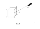
- Visibility of a face can be tested for using the camera position (given by the vector v ) and the corresponding surface normal n of a face as shown below by way of example in Fig. 6 .
- the surface normals of the object's faces and the camera position are defined simply in terms of the face's corner vertices.
- n is obtained from the cross product of two adjacent edges of the face.
- Texture extraction is only performed on faces that are visible. Thus, at any given instance (image), at most 3 textures are extracted, corresponding to any 3 visible faces.
- every pixel Q i in texture ABCD should map to a pixel within the quadrilateral abcd .
- the homography is calculated finding the linear solution of the equation above using the following constrains relating the four 2D corners of the face and the four corners of the output texture with width W and height H as:
- the homography is obtained, it is used to find and map every pixel in the texture, the corresponding pixel in the source image.
- the homography relates a point in a first plane to its corresponding position in a second under perspective projection.
- the computed 3D box model along with the computed rotation and translation matrices and the camera intrinsic K are used to predict the corners of the box in the image.
- the texture is defined as a rectangular image of redefined size as shown by way of example in Fig. 7 .
- the homography relates these two rectangular faces as given by: q i ⁇ H * Q i
- This value represents the quality of the texture: the higher the weight, the better the texture estimated.
- Fig. 10 shows an example of how textures are extracted from the source subsequent images captured by the user. In the following, it is shown how these various textures can be merged together successfully to compute one final texture per face of the object efficiently.
- Faces from which no information is available remain with a default texture or colour (e.g. transparency, black or chessboard). Furthermore, we allow the object to be symmetric; thus the left side face can be denoted to be similar to the right, thereby unifying the textures.
- a default texture or colour e.g. transparency, black or chessboard.
- the method always stores only the best extracted face texture from any one image. It does not merge multiple textures into one. For every image acquired, one computes the visible faces and first determines their weights. Then, at every point only the best texture and the corresponding weight is saved. "Best" is defined in terms of the computed weight. We replace face textures with a new texture only if the new texture has a higher weight. In other words, if the currently extracted face weight is better than what was previously computed, one replaces the previous texture with that extracted from the current image:
- the method combines the pixel values of all extracted textures of a face, giving priority to those textures with higher weights.
- N the number images acquired by the user.
- p i the value of the pixel in the i 'th image (extracted texture) taken by the user with corresponding weight w i
- N the number images captured by the user. Notice that N is the number of extracted textures for a certain face and not the total number of source images. For cases where the face is not visible, the corresponding weight is zero and the image is ignored.
- Fig. 11 shows by way of example how both heuristics work for the same set of extracted textures. Face 2 of Fig. 10 is used as an example.
- the embodiment as described as follows is even more generic and allows for greater flexibility in measuring objects even when the camera is uncalibrated.
- the marker is used the same way as described before and a single image is employed to compute both the size of the object and as a side effect the appropriate calibration matrix K of the used camera.
- One aspect of the invention relates to a method for generating a 3D model representation of a real-world object, comprising the steps of:
- the marker is a 2D marker, the layout and the real dimensions of the 2D marker being stored in a storing means, wherein the layout comprises: a polygon of pre-defined dimensions, preferably a rectangle or square, for example having a length of 16 cm and a width of 16 cm; a pre-defined identification pattern, for example three dots or squares arranged at the corners of an imaginary triangle, the identification pattern being arranged inside the polygon; wherein preferably the polygon and the identification pattern are printed or painted on a sheet of paper.
- the method comprises the further steps of:
- the method comprises the further steps of:
- At least four, preferably five, corner points of the virtual bounding box are selectable; and the method comprises the further step of:
- the method comprises the further step of:
- first plane being defined as the plane wherein the 2D marker is located and a second plane being defined as an arbitrary plane parallel to and different from the first plane:
- step (8d) the joint estimation of the height of the sector and the intrinsic matrix K is performed using the step:
- the estimation of the intrinsic matrix K in step (8d) relies on two assumptions:
- step (9a) of performing a line-search comprises the steps of:
- the method comprises the further steps of:
- step (12b) of analysing each of the snapshot(s) and extracting information from it comprises the steps of:
- step (13b) of computing textures comprises the following steps, wherein each of the following steps is to be applied to each of the faces of the selected sector:
- step (1d) of creating a 3D model representation of the real-world object comprises the step of:
- step (15a) is performed by taking only the best available texture of the textures obtained from one or more snapshot(s) taken in step (12a).
- step (15a) is performed by evaluating the weighted sum of each textures available from the snapshot(s), wherein preferably, for each of the faces and each of the snapshot(s), the weights are given by the dot product or scalar product of unit vector v pointing from the mean value of the vertices or the geometrical center of gravity of the face to the position of the camera and the normal unit vector n of the face.
- the user is enabled to store the 3D model representation or share the 3D model representation, for example online using one of various modalities such as e-mail, MMS, online-portals, etc.
- Another aspect of the invention relates to a method for visualising an object in a displayed scene, the method comprising the steps of:
- One embodiment of the invention relates to a method for visualising an object in a displayed scene, wherein the scene displayed in step (19a) is static, for example a pre-captured photograph.
- a further embodiment of the invention relates to a method for visualising an object in a displayed scene, wherein:
- a preferred embodiment of the invention relates to a method for visualising an object in a displayed scene, wherein a marker, for example a 2D marker, is embedded in the real scene, the method comprising the further steps of:
- the user is enabled to manipulate, for example, to translate and/or to rotate, the visualised object within the displayed scene.
- a further aspect of the invention relates to a method for virtually augmenting a scene with a real-world object, comprising the steps of:
- the size of the object can be defined in terms of its bounding box in 3D as shown in Fig. 12 .
- the user has to indicate from a single image the visual extents of the bounding box in order to compute the object's size.
- the user places the marker on or next to the object so that it is aligned with the edges of the object.
- aligning the marker with the edges is an intuitive subconscious act.
- discarding the rotation interaction reduces the number of interactions needed and therefore reduces complexity to the measuring task.
- the user first takes a snapshot image that allows for defining the bounding box. Thus, the three extents of the object that define its length, width and height should be visible.
- the system then processes the image to detect the presence of the marker as well as establishes point correspondences between the marker and its image. These correspondences define a homography H between the plane of the marker and the image.
- t ) is then derived (see [7] chapter 5). Having the camera pose and camera intrinsics makes it possible to render 3D objects in the world from the perspective of the user.
- the system then displays a control-cube of known size on the marker along with a control-pane allowing the user to select specific faces of the box to move and extrude the box thereby moving and resizing it.
- the user can select one face at a time, and swipe left or right to extrude that face of the box inwards (making the box smaller) or outwards (making it bigger). These operations allow the user to resize as well as translate the box in the plane of the marker.
- the system provides real-time feedback to the user by augmenting the acquired image with the correct perspective view of the manipulated control-cube.
- This perspective feedback is sufficient to reliably align the cubes edges with the bounding edges of the furniture.
- the size of the extruded control-cube then is exactly the size of the furniture.
- results of using the model manipulation with feedback on small android based smartphone will be presented.
- the user points the smartphone camera at the table with the marker placed below it, aligned with its front edge.
- the system detects the marker and computes the pose of the camera (user's perspective) with respect to the marker on the floor, and accordingly augments the view with a virtual control-cube.
- the control-pane allows the user to select various faces of the control-cube.
- the user first aligns the rear-face of the cube with the back of the table (b).
- the user extrudes out and in as required the various faces to visually determine the bounding box in the real world.
- Fig. 15 shows the object to measure ( l ⁇ h ⁇ b ) 138 ⁇ 73 ⁇ 59 cm 3 .
- the table's true dimensions are ( l ⁇ h ⁇ b ) 140 ⁇ 72 ⁇ 60 cm 3 .
- the experiments revealed measurements to be within a couple of centimeters of their true sizes.
- model manipulation approach as described above was suitable for small screens but required considerable number of interaction steps to align the control-cube with the extent of the object. Typically the user would need to iterate over the faces by adjusting and readjusting the faces (depending on the perspective) to eventually obtain the 3D size of the object.
- the user again takes a snap-shot of the object with the marker.
- the camera intrinsic matrix K is used together with the marker based homography H , to estimate the pose of the camera with regard to the marker. These parameters are then used to virtually place the control-cube upon the marker as before.
- the corners indicated by the user provide a correspondence between the control-cube corners and those of the object.
- the problem of determining the size of the object is then posed as that of determining the parameters needed to reshape the control-cube and move it in 3D so that resulting (resized) corners of the cube align with the image points indicated by the user.
- the reshaping comprises two transformations: scaling and then rotation and translation.
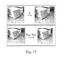
- the next step is to appropriately rotate and translate the resized cube (see Fig. 17 (bottom)) so as to match the furniture's real 3D location. Only then will the reshaped cube corners align with the points provided by the user.
- M m 11 m 12 0 m 14 m 21 m 22 0 m 24 0 0 m 32 0 0 0 0 1
- K is the intrinsic camera matrix
- R C and t C denote the pose.
- P K ⁇ R c
- the system can take advantage of larger screen devices by providing a more intuitive user interaction to obtain the box measurements and position.
- the idea is to obtain the box 3D coordinates in the world using only the information of the 2D markers.
- the system is also capable of automatically extracting textures from the object's images. The textures are then used for image based rendering of furniture virtually placed in the scene.
- the homography is calculated knowing that the four vertices of the textures correspond to the four vertices of the face in the source image.
Landscapes
- Engineering & Computer Science (AREA)
- Physics & Mathematics (AREA)
- Theoretical Computer Science (AREA)
- Computer Graphics (AREA)
- General Physics & Mathematics (AREA)
- Geometry (AREA)
- Software Systems (AREA)
- Computing Systems (AREA)
- Computer Hardware Design (AREA)
- General Engineering & Computer Science (AREA)
- Processing Or Creating Images (AREA)
Abstract
Description
- The present invention relates to an augmented reality system and a method of augmented reality, and in particular to an augmented reality system and a method of augmented reality allowing for measurement, 3D modeling and visualization of real world objects.
- Increasing power of mobile devices and smartphones has significantly contributed to the progress of augmented reality (AR) applications becoming mobile. While early mobile AR application truly focused on the mobile user, addressing location based applications (see [2]). The current trend is to move traditional AR to the mobile (hand-held) device. These AR applications typically use image features (in the form of 2D Markers, [3]) to visually localize the user to a local coordinate frame rather than GPS based location.
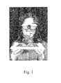
- The field of augmented reality is all about imaging a real scene and augmenting it with objects that do not really exist in that scene. As shown in
Fig. 1 , the camera observes the scene consisting of a person holding up a visual 2D marker. The AR system then automatically places on this marker a 3D graphical model virtually in the scene. - Typically, the marker in AR applications is used to determine the perspective at which the camera views the scene. By perspective we refer to the camera's pose (location and orientation, referred to as "pose") with respect to the marker as well as the camera lens and resolution properties (such as focal length, principle point, etc., together referred to as "camera intrinsics") that determine how it scales and forms an image from that pose. In order to augment this scene with a 3D object, one must also know the position of this object with respect to the marker as well as a 3D model and textures for it.
- When working with graphically modelled 3D objects, the 3D model or shape is completely known. Furthermore, the textures used to render or colour the objects are also known. Thus, the only source of error and difficulty arises in determining the pose of the camera to which to render the graphical object. However, this is pretty much solved using the 2D marker and or other sources. Thus, in principle, rendering 3D graphical objects virtually in a real scene (AR with graphical objects) is relatively straightforward. The problem arises when dealing with the need to virtually place real 3D objects in an AR application.
- While many such AR applications address themes in entertainment, education/training, interaction (see [1, 5, 6]) with virtual objects, none allows the user to capture and manipulate real world objects around them. In more general words, while the idea of displaying intricate authored 3-D models is not novel (see [5]), none of the systems known from prior art allow for augmentation with user generated 3D content of real-world objects.
- In order to generate accurate views of real objects in order to place them virtually in a scene for AR, one needs to know the accurate texture of these objects and 3D models of them. When dealing with real-world objects, this becomes a challenging problem. Computing accurate 3D models of real-world objects is a research field itself. Furthermore, accurate visual modelling of a real-world object requires understanding its appearance over a variety of views and under various lighting conditions which makes accurate visual modelling extremely hard.
- A field of application of AR with real-word objects is, for example, the following: While manually measuring objects such as furniture would provide very accurate results, it does not always provide the sense of space occupied by an object. The look and sheer size of an object cannot be captured by a few numbers denoting the dimensions alone. Moreover, the problem is further complicated if the object in question is heavy and cannot be moved around easily or, even worse, is still not at hand (for example at a shop). It is with these circumstances in mind that the present invention was developed.
- From the above it becomes clear that there is a need for an augmented reality system and a method of augmented reality allowing for measurement, 3D modeling and visualization of real world objects such as, for example, furniture.
- The objective of the present invention is thus to provide an augmented reality system and a method of augmented reality allowing for measurement, 3D modeling and visualization of real world objects.
- This objective is achieved by the method and the system with the features as defined in the claims presented in this document.
- The invention can be summarised as follows:
- One aspect relates to a novel vision based augmented reality system to facilitate the measurement, 3D modeling and visualization of furniture and other objects preferably on any mobile device. The system utilizes a 2D marker in the scene to allow intuitive and
- visual interaction with a single image to measure object dimensions and acquire a 3D primitive based model with textures. The textures are automatically extracted from multiple images of the object. The system thus allows the user to capture textured 3D models and place them virtually elsewhere using the marker. Furthermore, according to a further aspect it is shown hereunder how metric measurement and modeling can be performed from a single image even when the camera is uncalibrated.
- The novel system allows the user to photograph furniture or other objects using their mobile camera and directly measure their sizes from the image alone. Furthermore, once measured, the system allows the user to walk around the object and take more photographs and automatically compute image based textures for the 3D models. Finally, using a marker to determine the user's perspective, the furniture is rendered in real-time in a new position/environment. A standard smartphone equipped with a camera is then capable of providing the user with a live view of the world. Our invention then allows the user to enjoy a live walk about the modeled objects, e.g. furniture, in real-time.
- The invention provides a simple way to use minimal geometric shapes as primitives to model real-world objects together with IBR (image based rendering) techniques to determine accurate textures of real-world objects for purposes of augmented reality and other applications. By simply determining a bounding box for the object, the approach according to the invention directly computes the colour textures for the object and creates a virtual model with texture for AR applications.
- The method according to the invention allows anyone to build a textured 3D model of an object. The method enables the user to measure precisely the furniture or object in question as well as to collect samples of images as textures which are automatically extracted. Next, the user can share this model and textures with anyone either via the web or directly via messaging or other means of sharing.
- The AR system according to the invention, as illustrated by way of example in
Fig. 12 , allows the user to measure an object reliably (within acceptable margins of error) and capture images from which a texture mapped 3D model is computed as well as to use the textured models to virtually place and manipulate the object in a new location. Thus, not only the size of the object is determined, but the object can be viewed in real-time in another location. Furthermore, it is possible to virtually walk around the object and to get a better sense of its size and the space occupied by it. - The method described in this document contains the following components that together enable the easy creation of 3D models and "Image based Textures" of real world objects as shown by way of example in
Fig. 2 . - The method enables any user (without specialized training or skills) to be able to interactively measure accurately any 3D object. Furthermore, the method completely automatically computes a real Image based Texture model from a few images of the object.
- Once the 3D model and textures are automatically computed, the user can then easily share these with anyone using multiple possibilities. The method allows the user to share models just like one shares images. Other users can then visualize the 3D object virtually with the same real image textures in remote locations virtually. The remote users simply download the models and then can see the object, e.g. the furniture, in a different environment, e.g. their own homes, from any perspective (viewing angle etc.) in real-time.
- The sharing of 3D models and IBR textures enables many applications including e-commerce of objects over the internet. The technology does not only apply for corporations (big or small), but also to individually trading objects online. Instead of simply having images of the object (furniture) being sold, one can now also include these 3D models and textures. The remote buyer can then download the models to his/her mobile device or computer and then visualize the object in their own home or office or other environment.
- In this system, the marker is used to determine the scale and pose of the camera with respect to the piece of furniture (cupboard, chair, table etc.) being measured. The measurement itself is carried out semi-interactively by the user visually changing the size of a virtual bounding box in the viewfinder of his device so as to enclose the furniture as shown by way of example in
Fig. 3 . - By doing so, the user not only determines the exact dimensions of the object, but also provides a primitive 3D model of the object. Now, by moving the camera around the object, the user can automatically acquire multiple views of the object for which the camera's pose is determined using the marker, which together with the 3D bounding box provides ample information to compute a visual model for the object. From the multiple images and the 3D model, both view independent (for Lambertian objects) as well as view dependant representations can be determined, that can be used for real-time rendering of the same object, e.g. piece of furniture, in another scene virtually.
- Thus, using the primitive and already available 3D bounding box and multiple images of the object, the user can later virtually place this object in any other real scene (augment a remote scene) so as to visualize not only its size there but also its appearance and how it blends with the other objects in that scene.
- In general, to make any metric and geometric analysis of the image, the camera's pose (rotation R and translation t) with respect to the scene need to be determine. Also, the scale of objects in the image needs to be determined; perspective images have no notion of depth and scale such that from an image alone it is in fact impossible to make Euclidean measurements without some knowledge of scale and geometry. Therefore, the standard approach of 2D markers similar to [4] is employed. Moreover, as measurement is impossible without a calibrated camera, calibration is done automatically using a few images of the marker (see [8]). Thus, the markers not only provide a scale of objects in the scene, but also allow determining the camera pose.
- In order to measure objects in the scene from an image (in the following also referred to as "visual metrology"), it has to be determined where exactly the object of interest lies within the image. Since automatic segmentation of the object of interest is relatively challenging, especially for the purpose of robust measurement, user interaction is preferred to define the extent of the object, e.g. furniture, being measured. As shown by way of example in
Fig. 12 , the user visually marks out the bounding box as would be visible in the image. - As shown by way of example in
Fig. 2 , the bounding box already provides a good yet primitive 3D model of the object being measured. While being able to compute the size of an object is interesting, it alone does not convey the full extent of how that object would feel in another environment. In order to get a better and more complete sense of the space occupied by the object, it is necessary to be able to capture the object and place it virtually in another location. The user should be able to virtually walk around it and "feel" its presence. This is only possible if the virtual placed furniture not only has the size of the original object but also the appearance. - The key step to the augmented reality application for real-world objects is the ability to virtually place, move and manipulate an object in an environment. To do so, again the marker to determine the camera's pose is employed. Then, a realistic view of the furniture in true size depending on the position of the user is rendered.
- The user is enabled to move (translate on the ground) the object and rotate it about its axis. The interaction metaphors are in line with those used in visual metrology.
- Image based rendering (IBR) is employed to compute textures for the object model. Once the object's position and size is precisely measured via visual metrology, the user is then capable of capturing multiple still-shots of the furniture. For every image acquired, the system automatically processes it to extract relevant texture information. Moreover, using the marker already in place, one can acquire multiple images from different positions so as to "image" the various sides of the furniture. In the following, details of our semiautomatic method for 3D model and texture extraction for real-time augmentation of scenes with real-world objects will be presented.
- From the user's perspective, he/she is provided a live view of the bounding box that represents the object rendered in real-time exactly where the object lies in the scene. As the user moves around the object, the bounding box also relatively is shown to match the position and size of the object. The user then simply clicks to take snapshots of the object from different positions to reveal the different sides/faces of the object.
- The user can thus take as many snapshots of the object from different positions as he or she wishes. At every snapshot, we automatically extract the textures for the visible faces of the object from the current image. These current face textures are used together with past face textures previously extracted to compute a final texture of every face. Every time the user takes a snapshot, the method automatically extracts textures from this image for the visible faces of the object. Each extracted face texture is then used together with previously extracted face textures to compute a final texture representation as will be described below.
- For every image taken by the user, the system first determines the marker and the pose of the camera relative to it and the user defined bounding-box (in 3D). Using this information, it is determined which of the 6 faces of the bounding box are actually visible in the camera's view. Next, the image projection of the 8 vertices of the wire-frame box in the view of the camera is computed. In doing so, essentially the regions within the image corresponding to every face (side) of the bounding box are determined.
- In order to compute a rectangular texture image for every (rectangular) face of the bounding box, one simply needs to morph the corresponding underlying image regions into a rectangle. This image morph in fact is simply the homography relating the four real world corners of the bounding box (in 3D) to the four image corners of the corresponding texture. Once the homography between the 3D corners of a face and its image corners is determined (linear solution), the texture image is easily determined by re-sampling the image region accordingly. Details of this process are described next.
- As mentioned above, our goal is to create a 3D texture model of an object, for example the furniture from
Fig. 5 , based on textures that are extracted from images taken by the user of the real-world object. As shown inFig. 5 , the 3D model of the box is represented by its 3D vertices A, B, C, D, E, F G, H. The corresponding 2D image coordinates in the captured image are (a, b, c, d, e, f, g, h). - For any object, from any given position of the user, at most 3 faces can be "visible" at once. As shown in the example of
Fig. 5 , the visible faces of the white couch include faces defined by the vertices ABCD, ADHE and DCGH in the image. In contrast, the faces ABFE, BCGF and EFGH are not visible to the user in the given image. In order to extract textures for the various possible faces, it is first determined which of the 6 possible faces are indeed visible in the given image. Visibility of a face can be tested for using the camera position (given by the vectorv ) and the corresponding surface normaln of a face as shown below by way of example inFig. 6 . - The surface normals of the object's faces and the camera position are defined simply in terms of the face's corner vertices. Considering, e.g., the face CBFG, the center of the face CF is calculated by finding the mean value of the four vertices of that face:

- The camera vector
v 17 is the unit length vector between the camera position CP and the center of the face CF :
- The vector
n is obtained from the cross product of two adjacent edges of the face. In our example, edges GF and GC are used:
- Since
v andn are unit vectors, the dot product represents the cosine of the angle between them. The face is "visible" only for positive values of Cf =v ·n . - Texture extraction is only performed on faces that are visible. Thus, at any given instance (image), at most 3 textures are extracted, corresponding to any 3 visible faces.
- For the visible faces, one now computes textures for each of these. That means that the color information for every pixel Qi = (Xi , Yi ) of the texture (
Fig. 6 , right) is obtained from some pixel qi = (xi, yi) in the source image (Fig 6 , left). To do that, the homography matrix H (in the following also simply referred to as "homography") is needed, which relates Qi with qi . - For example, as shown in
Fig. 7 , every pixel Qi in texture ABCD should map to a pixel within the quadrilateral abcd. - The relation of Qi with qi through the standard homography matrix H is given by:

wherein

- The homography is calculated finding the linear solution of the equation above using the following constrains relating the four 2D corners of the face and the four corners of the output texture with width Wand height H as:
- Corner A = (1,1) of the texture maps to the point a in the image
- Corner B = (W, 1) of the texture maps to the point b in the image
- Corner C = (W, H) of the texture maps to the point c in the image
- Corner D = (1, H) of the texture maps to the point d in the image
- Once the homography is obtained, it is used to find and map every pixel in the texture, the corresponding pixel in the source image.
- In other words, the homography relates a point in a first plane to its corresponding position in a second under perspective projection.
- Referring to
Fig. 7 , the computed 3D box model along with the computed rotation and translation matrices and the camera intrinsic K are used to predict the corners of the box in the image. Thus, when a user takes a picture of the object after having "measured" the object, one immediately knows where every corner of the box would "project to" in that image. These corners define the source image corners qi = (xiyi ) in the image. Then, the texture is defined as a rectangular image of redefined size as shown by way of example inFig. 7 . Now the homography relates these two rectangular faces as given by:
- Here, for every rectangular face corner qi in the image, a known texture corner Qi is associated. Insofar, H is unknown and must be estimated The correspondence between the four corners of the object face and texture provide 8 constraint equations that are sufficient to solve for H.
- From every new image a maximum of 3 face textures can be extracted. Thus, it is possible that over the course of multiple images taken by the user, one can obtain many textures from the same face. Therefore, a criterion is needed to estimate the final texture. In order to combine or select between various estimates of the same face texture, for every extracted face texture a weight is computed that denotes its quality.
- To calculate the weight of a texture, two factors are considered:
- The resolution or area in pixels of the quadrilateral region in the source image, from where the texture pixels where mapped. The bigger the area the better the resolution of the texture.
- The viewing angle of the camera relative to a face. This value has already been calculated as the cosine of the angle between the camera vector
v and the surface normaln of a face (see above). Usually, this means that a frontal view of the face is preferred to an oblique one. - If the four vertices of a quadrilateral face are (xa , ya ), (xb , yb), (xc, yc ), and (xd , yd ), the area Ai f for face f and source image i can be calculated as:

- This is exemplarily demonstrated in
Figs. 8 and19 . - Together with the visibility factor Ci f =
v i ·n f the weight of a texture can be defined as:
- This value represents the quality of the texture: the higher the weight, the better the texture estimated.
-
Fig. 10 shows an example of how textures are extracted from the source subsequent images captured by the user. In the following, it is shown how these various textures can be merged together successfully to compute one final texture per face of the object efficiently. - As mentioned above, it is desired to have a final texture for every face of the object. In principle, different approaches are possible to use multiple images of the object, extract the "visible" faces and the corresponding weights and then combine them appropriately. Once we have the weight information as criterion of how good a texture is, different heuristics to get a final texture are possible. In the following, two heuristics (methods) are disclosed that can be used to compute the final face textures. Both methods are greedy approaches, which means that after every image taken by the user is processed, the "best possible" final texture is computed directly. The advantage is that it is not required to save all the extracted textures on the device. At any instance, only 6 face textures representing the final face textures are stored. However, this does not exclude to have other kinds of heuristics that save all extracted textures and create a final image in the future.
- Faces from which no information is available remain with a default texture or colour (e.g. transparency, black or chessboard). Furthermore, we allow the object to be symmetric; thus the left side face can be denoted to be similar to the right, thereby unifying the textures.
- According to one embodiment, the method always stores only the best extracted face texture from any one image. It does not merge multiple textures into one. For every image acquired, one computes the visible faces and first determines their weights. Then, at every point only the best texture and the corresponding weight is saved. "Best" is defined in terms of the computed weight. We replace face textures with a new texture only if the new texture has a higher weight. In other words, if the currently extracted face weight is better than what was previously computed, one replaces the previous texture with that extracted from the current image:
- For every visible face f i :
- If no previous texture of this face has been saved, then save t i_new as the final texture of the face f i.
- If a texture t i old with weight wold has already been saved, then compare the weights of both textures:
- ○ If w i_new is greater than wold, then replace t i_old with t i_new and replace w old with w new.
- ○ Otherwise, keep t i_old as the actual texture.
- It is noticed that this greedy approach leads to sharp images and has a much higher user acceptance than normalized weighted textures.
- According to another embodiment, the method combines the pixel values of all extracted textures of a face, giving priority to those textures with higher weights.
- Given N images acquired by the user, the value P N for every pixel in the final texture (using these N images) is calculated by:

where pi is the value of the pixel in the i'th image (extracted texture) taken by the user with corresponding weight wi , and N is the number images captured by the user. Notice that N is the number of extracted textures for a certain face and not the total number of source images. For cases where the face is not visible, the corresponding weight is zero and the image is ignored. - It should be noted that in practice it is not needed to store all the N images in memory in order to compute the weighted final texture. Instead, a final texture representation is kept in terms of a moving average which precludes the need for N independent images, thereby drastically reducing the required memory by a factor of N.
- Consider the first t images in a sequence of N, the pixel value Pt after t textures have been processed, with 1 ≤t ≤N is given by:

where P̃t is the non-normalized pixel value and Wt the normalizing sum of weights. Both values are independently saved after a new output texture is created. By doing this, when a new texture i +1 is processed, one can compute P t+1 without knowing previous values (i ≤t) of wi and pi as:
-
Fig. 11 shows by way of example how both heuristics work for the same set of extracted textures.Face 2 ofFig. 10 is used as an example. - The embodiment as described as follows is even more generic and allows for greater flexibility in measuring objects even when the camera is uncalibrated. The marker is used the same way as described before and a single image is employed to compute both the size of the object and as a side effect the appropriate calibration matrix K of the used camera.
- The advantage of this approach is that one can perform 3D model estimation and texture extraction (as a consequence) from images alone without access to the camera intrinsics at all. Thus, even from online images or pre-captured images of objects with the marker in place, one can perform the task of measuring and textured model estimation.
- It is assumed the user has taken a picture or has a picture of an object and the marker. As before a marker detection is performed in order to infer the homography between the corners of the marker in the image (say qi ) and the physical marker (Qi ) (in the plane of the marker) given by the constraint:

- Then the method according to this embodiment comprises the steps of:
- 1. From this relationship H is estimated.
- 2. The user then clicks or indicates various points that define the periphery of the object on the ground plane with the marker as shown by way of example in the
Fig. 20 . - 3. Together with the homography computed in
step 1, one then can project every image corner defined by the user to its true location on the ground. Thus one can then determine exactly the length and width of the object. - 4. Next, the user essentially presents the system with a corresponding "top" point for one or more of the corners.
- 5. Next, the system uses these points and the homography to jointly estimate the height of the object while simultaneously determining the intrinsic matrix that satisfies the following constraint.
- a. In general this problem is not solvable; however, one can enforce acceptable constraints on the K matrix to solve the problem.
- i. It is assumed that the camera system has zero skew as well as that the pixels are square (aspect ratio = 1).
- b. The K matrix is then given by:

- c. Let the points of the object on the ground plane (with marker be Qi = (Xi , Yi , 0,1) where the Z coordinate is zero (height from floor is zero).
- d. Then the corresponding top corners would be

Z . - e. The next step is the non-linear search (optimization) for
Z , so that the projection of the points in 3D align to those in the image (provided by the user and the marker) while ensuring that the K matrix is as constrained in (b).- i. This is solved by first determining the projection matrix P by solving the constraint:

Where Q denotes the combination of all points Qi and
- ii. Next we perform RQ decomposition of P̃ to determine
K̃ andR̃ , the rotation matrix. - iii. This estimate K̃ need not adhere to the required constraint and hence we define the objective function F, that is to be minimized as:
F(K̃) = K(1,2)2, corresponding to minimizing the element (1, 2) of the matrix, or thereby minimizing skew.
- i. This is solved by first determining the projection matrix P by solving the constraint:
- a. In general this problem is not solvable; however, one can enforce acceptable constraints on the K matrix to solve the problem.
- 6. The optimization results in estimation of a non-zero Z, that is essentially the required height of the furniture.
- One aspect of the invention relates to a method for generating a 3D model representation of a real-world object, comprising the steps of:
- (1a) obtaining a picture of a real-world object together with a marker, the object and the marker being embedded in a real scene;
- (1b) detecting the marker in the picture;
- (1c) measuring the dimensions of a selected sector in 3D using the information provided by the marker detected in step (1b);
- (1d) creating a 3D model representation of the real-world object.
- In one preferred embodiment, the marker is a 2D marker, the layout and the real dimensions of the 2D marker being stored in a storing means, wherein the layout comprises: a polygon of pre-defined dimensions, preferably a rectangle or square, for example having a length of 16 cm and a width of 16 cm; a pre-defined identification pattern, for example three dots or squares arranged at the corners of an imaginary triangle, the identification pattern being arranged inside the polygon; wherein preferably the polygon and the identification pattern are printed or painted on a sheet of paper.
- Preferably, the method comprises the further steps of:
- (3a) analysing the marker's position in the picture;
- (3b) computing or estimating the homography H with respect to the marker in the picture; and wherein
- preferably the steps (3a) and (3b) are performed after step (1b).
- In a further embodiment, the method comprises the further steps of:
- (4a) enabling the user to select a sector within the picture, the sector corresponding to a 3D sector in the real-world embedding the object; and preferably further comprising the steps of:
- (4b) computing a perspective view of a virtual bounding box, wherein the virtual bounding box is preferably a cuboid, and more preferably a cube;
- (4c) overlaying the picture with the perspective view of the virtual bounding box, wherein the virtual bounding box is preferably placed on top of the marker.
- One embodiment of the method comprises the further step of:
- (5a) allowing the user to shift each face of the virtual bounding box such that the object is enclosed within the virtual bounding box, the virtual bounding box thereby indicating a sector corresponding to a 3D sector in the real-world embedding the object.
- In a further embodiment of the method, at least four, preferably five, corner points of the virtual bounding box are selectable; and the method comprises the further step of:
- (6a) enabling the user to select each of the selectable points, preferably by a clicking or touching operation, and to connect the respective point by a drag-and-drop operation to the corresponding corners of the sector to be selected.
- Preferably, the method comprises the further step of:
- (7a) estimating the calibration of the camera used to obtain the picture provided in step (1a).
- In one preferred embodiment of the method, with a first plane being defined as the plane wherein the 2D marker is located and a second plane being defined as an arbitrary plane parallel to and different from the first plane:
- step (4a) of enabling the user to select a sector and step (7a) of estimating the calibration are performed together using the steps of:
- (8a) enabling the user to select a number of three or more points in the first plane so as to select a base area of the sector to be selected;
- (8b) determining the dimensions of the base area using the information provided by the homography H computed or estimated in step (3b);
- (8c) enabling the user to select at least one point(s) of a set of points given by the piercing points of the second plane with each of the lines orthogonal to the first plane and piercing the three or more points selected in step (8a), so as to select a height of the sector;
- (8d) using the point(s) selected in step (8c) and the homography H to jointly estimate the height of the sector while simultaneously estimating the intrinsic matrix K describing the calibration of the camera.
- In an embodiment of the method, in step (8d) the joint estimation of the height of the sector and the intrinsic matrix K is performed using the step:
- (9a) performing a line-search, for example a non-linear line-search, for obtaining an optimised estimation of the real height
Z̅ of the sector such that the projection of the estimated 3D real-world coordinates of the points of the sector corresponding to the points selected in step (8c) onto the image aligns with the respective coordinates of the points of the perspective view of the sector as selected in step (8c). - In a further embodiment of the method, the estimation of the intrinsic matrix K in step (8d) relies on two assumptions:
- (i) the camera system has zero skew, and
- (ii) the pixels are square with an aspect ratio equal to one; and wherein
the line-search in step (9a) is performed while ensuring that the intrinsic matrix K is as constrained by the assumptions (i) and (ii). - Preferably, step (9a) of performing a line-search comprises the steps of:
- (11a) determining the projection matrix P describing the projection of the estimated 3D real-world coordinates of the points of the sector corresponding to the points selected in step (8c) onto the respective coordinates of the points of the perspective view of the sector;
- (11b) performing a decomposition, for example an RQ decomposition, of the projection matrix P to obtain first estimations K̃ and R̃ for the intrinsic matrix and the rotation matrix, respectively;
- (11c) minimising a suitable objective function F that takes the first estimation of the intrinsic matrix K̃ or at least one element of the first estimation of the intrinsic matrix K̃ as argument(s) in order to minimise the skew described by K̃ ;
- (11d) obtaining an estimated value for the real height
Z̅ of the sector from the result of the minimisation as performed in step (11c). - In one embodiment, the method comprises the further steps of:
- (12a) enabling the user to take one or more snapshot(s) of the selected object from various directions using a camera;
- (12b) analysing each of the snapshot(s) and extracting information from it; and
wherein preferably step (1a) of obtaining a picture of a real-world object together with a marker is performed by means of a live-view video. - Preferably, step (12b) of analysing each of the snapshot(s) and extracting information from it comprises the steps of:
- (13a) evaluating the visibility for each of the faces of the selected sector;
- (13b) computing textures for each of the visible faces of the sector; and wherein preferably step (13a) of evaluating the visibility comprises the following steps, wherein each of the following steps is to be applied to each of the faces of the selected sector:
- (13c) finding the mean value of the vertices or the geometrical center of gravity of the face;
- (13d) computing the unit vector
v pointing from the mean value of the vertices or the geometrical center of gravity of the face to the position of the camera, wherein the position of the camera can be obtained using the information provided by the image of the marker located in the picture; - (13e) computing the normal unit vector
n of the face, for example by taking the cross product of two linearly independent edge vectors of the face and dividing the result by its norm; - (13f) taking the dot product or scalar product of unit vector
v pointing from the mean value of the vertices or the geometrical center of gravity of the face to the position of the camera and the normal unit vectorn of the face. - In one embodiment of the method, step (13b) of computing textures comprises the following steps, wherein each of the following steps is to be applied to each of the faces of the selected sector:
- (14a) evaluating a homography matrix HFace relating the perspective view of the face visible in the picture to a texture-area, wherein the texture-area is preferably defined as a rectangular image of pre-defined size;
- (14b) obtaining a texture by mapping the face onto the texture-area by using the matrix HFace.
- In a further embodiment, step (1d) of creating a 3D model representation of the real-world object comprises the step of:
- (15a) finding an optimised texture for each of the faces of the selected sector by comparing and/or superposing the textures obtained from each of the one or more snapshot(s) taken in step (12a) with step (14b).
- In still a further embodiment, step (15a) is performed by taking only the best available texture of the textures obtained from one or more snapshot(s) taken in step (12a).
- In yet a further embodiment, step (15a) is performed by evaluating the weighted sum of each textures available from the snapshot(s), wherein
preferably, for each of the faces and each of the snapshot(s), the weights are given by the dot product or scalar product of unit vectorv pointing from the mean value of the vertices or the geometrical center of gravity of the face to the position of the camera and the normal unit vectorn of the face. - In one preferred embodiment, the user is enabled to store the 3D model representation or share the 3D model representation, for example online using one of various modalities such as e-mail, MMS, online-portals, etc.
- Another aspect of the invention relates to a method for visualising an object in a displayed scene, the method comprising the steps of:
- (19a) displaying a scene;
- (19b) creating an image of an object represented by the 3D model generated by the method of any of
claims 1 to 18; - (19c) overlaying the image of the object onto the displayed scene.
- One embodiment of the invention relates to a method for visualising an object in a displayed scene, wherein the scene displayed in step (19a) is static, for example a pre-captured photograph.
- A further embodiment of the invention relates to a method for visualising an object in a displayed scene, wherein:
- the scene displayed in step (19a) is non-static, for example a live-view video of a real-world scene; and
- step (19c) of overlaying the image of the object onto the displayed scene is preferably performed in real-time.
- A preferred embodiment of the invention relates to a method for visualising an object in a displayed scene, wherein a marker, for example a 2D marker, is embedded in the real scene, the method comprising the further steps of:
- (22a) computing the camera's position relative to the marker;
- (22b) adapting the size of the object virtually placed into the displayed scene by using the information computed in step (22a).
- In one embodiment of the method for visualising an object in a displayed scene, the user is enabled to manipulate, for example, to translate and/or to rotate, the visualised object within the displayed scene.
- A further aspect of the invention relates to a method for virtually augmenting a scene with a real-world object, comprising the steps of:
- (24a) generating a 3D model representation of the surface texture(s) of a real-world object according to the method of the invention for generating a 3D model representation of a real-world object;
- (24b) visualising an object in a displayed scene according to the method of the invention for visualising an object in a displayed scene.
-
- Fig. 1:
- A typical example of AR using a 2D marker that is detected and used for augmenting the world with a metrically scaled 3D object. Adapted from [1].
- Fig. 2:
- The various modules that together enable easy capture of the 3D model of the object together with Image based textures for real-time augmented reality rendering.
- Fig. 3:
- Use of a 2D marker for furniture measuring AR applications. The 2D marker is automatically detected in order to determine camera pose and relative size of objects in the scene with respect to their sizes in the image. The shown bounding box is then virtually reshaped and placed to encompass the furniture being measured. This simple approach directly provides the precise size of the furniture.
- Fig. 4:
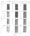
- Using multiple views of a measured object to acquire textures for the corresponding faces of the rectangular block model. The left most column illustrates two sample views of the object being measured with the aid of a marker which provides scale and pose of the camera. The lower left image illustrates the bounding box used to indicate the object being measured. The remaining two columns indicate the synthesized images corresponding to each acquired view. The center column indicates two possible "top-views" of the object, while the right column provides a side and front view, respectively. These views are automatically computed and will be used to compute an effective texture for the object.
- Fig. 5:
- Depending of how the bounding box is defined to match the object, we have correspondences of the 3D vertices A, B, C, D, E, F, G, H to their corresponding 2D image location a, b, c, d, e, f, g, h in the image.
- Fig. 6:
- Visual representation of vectors camera position
v and surface normaln needed to determine visibility of a face, here: CBFG. A positive dot product determines whether the face is visible from the given camera position. - Fig. 7:
- Homography is calculated based in the correspondences of 3D vertices A, B, C and D to the 2D vertices a, b, c and d. Once obtained, the homography is used to find the corresponding pixel qi on the source image and map it to the texture Qi .
- Fig. 8:
- The 2D vertices a, b, c, d of face ABCD are used to calculate the area of that face regarding a specific texture.
- Fig. 9:
- Examples of textured objects rendered virtually into new scenes. The textures were computed using our automatic method. While (a) represents just a view of the virtually rendered object using extracted textures, (b), (c), and (d) represent virtually placed objects using our extracted textures in new environments. Placing a virtual object with natural textures extracted from the object itself gives the user a much better and realistic view of the object in its new "home."
- Fig. 10:
- For every source image, the viewing angle of every face is calculated to determinate wish faces of the object are visible. For all visible faces, the area is calculated and a weight is given to the texture. Face 1 (back) and 6 (bottom) are not shown, since they are not visible from any view.
- Fig. 11:
- After a face texture is extracted from a source image, an output texture of that face is computed. Notice that no extracted texture is stored during the process. When analyzing the first extracted texture, the output of both heuristics is the same, since there is only one texture. After analyzing the second texture, the first texture remains as best texture, while, for "Weighted average texture" a mixed texture can be observed. After all textures are analyzed, the third remains as the output for "Best Texture," since is the one with highest weight. This fact is also noticed by the "Weighted average texture", where can be observed that the third texture has a preference in the final result.
- Fig. 12:
- The marker based AR system allows the user to interactively define the bounding box of an object and thereby determine its size. The system uses multiple images to determine a textured 3D model also utilized for AR based virtual furnishing.
- Fig. 13:
- Model manipulation with feedback interaction: Here, the user is allowed to choose the specific face of the bounding box to be moved. Then, a simple swipe of the finger either left/right extrudes the box along that face. Since the actual size of the 3D model is internally maintained, the visual overlay provides feedback in the image as to its fit to the object. When satisfied, this directly provides the size and position of the object/furniture with respect to the marker.
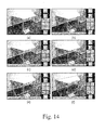
- Fig. 14:
- Android smartphone with model manipulation based interface for visual metrology. The user selects faces (b - f): rear, right, left, front and top, in order to directly manipulate a virtual bounding box to fit its view in the image. The control-cube provides the object size and position.
- Fig. 15:
- Result of measurement using a smartphone. Errors in measurement were about 2% of the true measures.
- Fig. 16:
- Direct Interaction - Exploiting the higher display size, one can use the greater resolution to directly point out to the system the correspondences between the unit box shown on the marker to those of the furniture. The system then computes directly the size and pose of the object in the room relative to the marker.
- Fig. 17:
- Modelling the bounding box in terms of a unit box B and the shape transform M. The shape transform models the resizing matrix S that defines the size of the bounding box explicitly as well as the rotation and translation required to align it with the real-world object as shown above.
- Fig. 18:
- A homography is used to find the corresponding pixel qi on the source image and map it to the texture Qi .
- Fig. 19:
- The 2D vertices a, b, c, d of face ABCD are used to calculate the area of that face regarding a specific texture.
- Fig. 20:
- Image showing he marker placed next to the object being measured. The user clicks the three visible corners on the base of the object (in the plane with the marker). This is sufficient (together with the homography) to determine the length and width of the object.
- Fig. 21:
- The user here presents the system with a 4th and 5th point pair corresponding to two of the three visible "top corners" of the object.
- Other aspects, features, and advantages will be apparent from the summary above as well as from the description that follows, including the figures and the claims.
- In the following, two interaction metaphors designed for small and large display devices, respectively, are presented. The mathematical assumptions and constraints imposed by each metaphor and their effect on robust estimation will also be explored. Snapshots of the system in action are also provided as well as results comparing real objects to captured and modeled objects using our system.
- Measurement of objects in the image requires human interaction as mentioned earlier. The size of the object can be defined in terms of its bounding box in 3D as shown in
Fig. 12 . The user, however, has to indicate from a single image the visual extents of the bounding box in order to compute the object's size. - In the following, two key interaction paradigms are disclosed that have been developed specifically with the display and interaction surface size in mind. On small smartphone displays, fine manipulations as required for geometric analysis are cumbersome. In contrast, larger displays allow greater freedom and flexibility for such direct interactions. These two contrasting approaches will be explored in the following.
- In general it is sufficient to indicate the object corners that define the bounding box of the object. However, this requires fine motor control for point selection which can be tedious on small screens. Therefore, a coarser movement (swipe to resize) paradigm has been developed that is less tedious while achieving the required accuracy.
- The user places the marker on or next to the object so that it is aligned with the edges of the object. Usually aligning the marker with the edges is an intuitive subconscious act. Furthermore, discarding the rotation interaction reduces the number of interactions needed and therefore reduces complexity to the measuring task.
- The user first takes a snapshot image that allows for defining the bounding box. Thus, the three extents of the object that define its length, width and height should be visible. The system then processes the image to detect the presence of the marker as well as establishes point correspondences between the marker and its image. These correspondences define a homography H between the plane of the marker and the image. Together with the camera intrinsics K, the camera pose (R | t) is then derived (see [7] chapter 5). Having the camera pose and camera intrinsics makes it possible to render 3D objects in the world from the perspective of the user.
- As shown in
Fig. 13 , the system then displays a control-cube of known size on the marker along with a control-pane allowing the user to select specific faces of the box to move and extrude the box thereby moving and resizing it. The user can select one face at a time, and swipe left or right to extrude that face of the box inwards (making the box smaller) or outwards (making it bigger). These operations allow the user to resize as well as translate the box in the plane of the marker. - The system provides real-time feedback to the user by augmenting the acquired image with the correct perspective view of the manipulated control-cube. This perspective feedback is sufficient to reliably align the cubes edges with the bounding edges of the furniture. The size of the extruded control-cube then is exactly the size of the furniture.
- It should be noted that the interaction forces either the top or the bottom of the control-cube to lie in the plane of the marker. This ensures avoiding any scale-depth ambiguities, i.e. ambiguities between a close by small object and a faraway large one in the image.
- Now, results of using the model manipulation with feedback on small android based smartphone will be presented. As shown in
Fig. 14 , the user points the smartphone camera at the table with the marker placed below it, aligned with its front edge. The system then detects the marker and computes the pose of the camera (user's perspective) with respect to the marker on the floor, and accordingly augments the view with a virtual control-cube. - On the right the control-pane allows the user to select various faces of the control-cube. The user first aligns the rear-face of the cube with the back of the table (b). Next starting with the right, left, front, and top, the user extrudes out and in as required the various faces to visually determine the bounding box in the real world. Note that although the object is not truly rectangular, it can still be measured accurately.
Fig. 15 shows the object to measure (l×h×b) 138×73×59 cm3. In fact the table's true dimensions are (l×h×b) 140×72×60 cm3. In most cases, the experiments revealed measurements to be within a couple of centimeters of their true sizes. - As noted before, the model manipulation although suited for small screens, is also restrictive since the user relies on feedback in the perspective view. Rotation control was omitted in order to avoid it's complexities under perspective projection. As a consequence, the marker must be precisely aligned with the edge of objects. Failure to align the marker would result in errors in measurement and subsequent steps including texture computation.
- Therefore, as an alternative embodiment, an approach as follows can be employed:
- The model manipulation approach as described above was suitable for small screens but required considerable number of interaction steps to align the control-cube with the extent of the object. Typically the user would need to iterate over the faces by adjusting and readjusting the faces (depending on the perspective) to eventually obtain the 3D size of the object.
- However, since the size of an object is determined by purely its length, width and height, all one needs are four corner points along the corresponding edges to compute its size. This indicates that the user should ideally be able to provide all necessary data by simply indicating the four points - four "touch/clicks" on the screen.
- The large screen size is exploited, which allows for better image resolution and visibility while also more comfortable fine motor control. Moreover, this approach—as shall be demonstrated—does not require the marker to be aligned with the furniture edges unlike before. This allows for more flexibility while providing robust estimates.
- As shown in
Fig. 16 , the user again takes a snap-shot of the object with the marker. As before the camera intrinsic matrix K is used together with the marker based homography H, to estimate the pose of the camera with regard to the marker. These parameters are then used to virtually place the control-cube upon the marker as before. - Instead of adjusting various cube faces, all the user must do is to drag-and-drop five corners of the cube onto the corresponding five corners of the objects. Note, that this correspondence is defined in the image and not in 3D. Furthermore it should be noted that although one needs four points minimally, the four points must indicate the length, width and height. For example, four points in a plane (one face of the object) do not provide the necessary constraints. By requiring the user to provide five points, it is assured that sufficient data is available in order to measure the object.
- Now the mathematical model used to estimate the size of furniture will be described. The corners indicated by the user provide a correspondence between the control-cube corners and those of the object. The problem of determining the size of the object is then posed as that of determining the parameters needed to reshape the control-cube and move it in 3D so that resulting (resized) corners of the cube align with the image points indicated by the user. The reshaping comprises two transformations: scaling and then rotation and translation.
- Consider the control-cube in
Fig. 17 (top). In order to fit the furniture it must first be scaled appropriately. The resizing is modeled by a diagonal matrix S = diag(sx , sy , sz ), where (sx, sy, sz ) correspond to the length, width and height of the furniture. - The next step is to appropriately rotate and translate the resized cube (see
Fig. 17 (bottom)) so as to match the furniture's real 3D location. Only then will the reshaped cube corners align with the points provided by the user. - Rotation is only in the ground plane (about the z axis) and can be defined by:

where θ is the rotation angle. The translation vector is:
It should be added that when the marker is on the floor, we can define the translation only in the ground plane, thereby tz = 0 , resulting in
- Using S, R Bw, and t BW, we define the reshaping matrix M that warps every point of the unit box to the
world 3D coordinate of the furniture. The reshaped corners of the control-cube are then given by:
where

- In order to linearise the above constraint (note the trigonometric elements in M), we can define M as a matrix with 7 degrees of freedom (dof) given by:

- Finally we need to define the relationship between the
world 3D coordinates


- Where K is the intrinsic camera matrix, and RC and tC denote the pose. Combining we define the projection matrix P as:

- Now it will be defined the relation between any 3D point


where m 11, m 12, m 21, m 22, m 33, m 14, and m 24 are unknown. - Every pair of points qi = (xi, yi , 1)T and

- Now will be presented results of measuring objects with direct interaction and reshaping based constraints. One clear advantage over the previous approach has been the reduced and simplified interaction needed from user to perform measurement.
- The system can take advantage of larger screen devices by providing a more intuitive user interaction to obtain the box measurements and position. The idea is to obtain the
box 3D coordinates in the world using only the information of the 2D markers. - As mentioned before, accurate measurement alone does not provide a full sense of the space occupied and appearance of furniture. For this purpose the system is also capable of automatically extracting textures from the object's images. The textures are then used for image based rendering of furniture virtually placed in the scene.
- After the 3D location of the box in the world is known, one can extract the face textures from different images. Using the coordinates of the furniture corners in 3D (obtained after measurement) together with the projected image corners multiple homographies per bounding box' face are estimated. Then, for every possible face the following steps determine texture computation:
- Check Visibility: For every image, determinate which faces are visible to the camera and which faces are occluded.
- Extract textures: Create a texture image of a face, using the available pixels in the original image. Since each texture is a rectangular image, resampling is done using the computed face homographies.
- Combine textures: Of all extracted textures of a face create one consistent texture image.
- From every image taken by the user it is possible to extract 1 to 3 faces, depending on the camera position. So, first one needs to determinate which faces are visible to the camera. As can be seen in
Fig. 6 , one computes the unit vectorsv from the center of the face to the camera location andn , the normal to the face. These two unit vectors can be calculated, since the 3D location of every vertex of the furniture and the camera position are known. Finally, sincev andn are unit vectors, their dot product (v ·n ) reveals whether the face is visible (v ·n > 0) or occluded (v ·n ≤0). - To create a texture, one needs to fill every pixel qi from the texture with a pixel Qi obtained from the source image. To do that, we need the homography H 3×3, which warps any point of the texture to a point in the image as shown in
Fig. 18 . - The homography is calculated knowing that the four vertices of the textures correspond to the four vertices of the face in the source image.
-
- [1] Chang, Y.-N., Koh, R.K.C., and Been-Lim Duh, H. Handheld AR games — A triarchic conceptual design framework. 2011 IEEE International Symposium on Mixed and Augmented Reality - Arts, Media, and Humanities, IEEE (2011), 29-36.
- [2] Feiner, S., MacIntyre, B., Hollerer, T., and Webster, A. A Touring Machine: ).
- [3] Kato, H. and Billinghurst, M. Marker tracking and HMD calibration for a video-based augmented reality conferencing system. Proceedings 2nd IEEE and ACM International Workshop on Augmented Reality (IWAR'99). IEEE Comput. Soc, 85-94.
- [4] Kato, H., Billinghurst, M., Poupyrev, I.., Imamoto, K., and Tachibana, K. Virtual object manipulation on a table-top AR environment. Proceedings IEEE and ACM International Symposium on Augmented Reality (ISAR 2000), IEEE (2000), 111-119.
- [5] Olsson, T. and Salo, M. Online user survey on current mobile augmented reality applications. 2011 10th IEEE International Symposium on Mixed and Augmented Reality, IEEE (2011), 75-84.
- [6] de Sa, M., Churchill, E.F., and Isbister, K. Mobile augmented reality. Proceedings of the 13th International Conference on Human Computer Interaction with Mobile Devices and Services - MobileHCl'11, ACM Press (2011), 749.
- [7] Yi Ma, Stefano Soatto, Jana Kosecká, S.S.S. An Invitation to 3-D Vision. Springer, 2004.
- [8] Zhengyou Zhang. Flexible camera, calibration by viewing a plane from unknown orientations. Proceedings of the Seventh IEEE International Conference on Computer Vision, IEEE (1999), 666-673 vol.1.
Claims (24)
- Method for generating a 3D model representation of a real-world object, comprising the steps of:(1a) obtaining a picture of a real-world object together with a marker, the object and the marker being embedded in a real scene;(1b) detecting the marker in the picture;(1c) measuring the dimensions of a selected sector in 3D using the information provided by the marker detected in step (1b);(1d) creating a 3D model representation of the real-world object.
- The method of claim 1, wherein:the marker is a 2D marker,the layout and the real dimensions of the 2D marker being stored in a storing means, whereinthe layout comprises:a polygon of pre-defined dimensions, preferably a rectangle or square, for example having a length of 16 cm and a width of 16 cm;a pre-defined identification pattern, for example three dots or squares arranged at the corners of an imaginary triangle, the identification pattern being arranged inside the polygon; whereinpreferably the polygon and the identification pattern are printed or painted on a sheet of paper.
- The method of claim 2, wherein the method comprises the further steps of:(3a) analysing the marker's position in the picture;(3b) computing or estimating the homography H with respect to the marker in the picture; and whereinpreferably the steps (3a) and (3b) are performed after step (1b).
- The method of any of claims 1 to 3, comprising the further step of:(4a) enabling the user to select a sector within the picture, the sector corresponding to a 3D sector in the real-world embedding the object; and
preferably further comprising the steps of:(4b) computing a perspective view of a virtual bounding box, wherein the virtual bounding box is preferably a cuboid, and more preferably a cube;(4c) overlaying the picture with the perspective view of the virtual bounding box, wherein the virtual bounding box is preferably placed on top of the marker. - The method of claim 4, with the further step of:(5a) allowing the user to shift each face of the virtual bounding box such that the object is enclosed within the virtual bounding box, the virtual bounding box thereby indicating a sector corresponding to a 3D sector in the real-world embedding the object.
- The method of claim 4, wherein at least four, preferably five, corner points of the virtual bounding box are selectable;
the method comprising the further step of:(6a) enabling the user to select each of the selectable points, preferably by a clicking or touching operation, and to connect the respective point by a drag-and-drop operation to the corresponding corners of the sector to be selected. - The method of claim 3 to 6, with the further step of:(7a) estimating the calibration of the camera used to obtain the picture provided in step (1a).
- The method of claim 7, wherein with a first plane being defined as the plane wherein the 2D marker is located and a second plane being defined as an arbitrary plane parallel to and different from the first plane:step (4a) of enabling the user to select a sector and step (7a) of estimating the calibration are performed together using the steps of:(8a) enabling the user to select a number of three or more points in the first plane so as to select a base area of the sector to be selected;(8b) determining the dimensions of the base area using the information provided by the homography H computed or estimated in step (3b);(8c) enabling the user to select at least one point(s) of a set of points given by the piercing points of the second plane with each of the lines orthogonal to the first plane and piercing the three or more points selected in step (8a), so as to select a height of the sector;(8d) using the point(s) selected in step (8c) and the homography H to jointly estimate the height of the sector while simultaneously estimating the intrinsic matrix K describing the calibration of the camera.
- The method of claim 8, wherein in step (8d) the joint estimation of the height of the sector and the intrinsic matrix K is performed using the step:(9a) performing a line-search, for example a non-linear line-search, for obtaining an optimised estimation of the real height
Z of the sector such that the projection of the estimated 3D real-world coordinates of the points of the sector corresponding to the points selected in step (8c) onto the image aligns with the respective coordinates of the points of the perspective view of the sector as selected in step (8c). - The method of claim 9, wherein
the estimation of the intrinsic matrix K in step (8d) relies on two assumptions:(i) the camera system has zero skew, and(ii) the pixels are square with an aspect ratio equal to one; and whereinthe line-search in step (9a) is performed while ensuring that the intrinsic matrix K is as constrained by the assumptions (i) and (ii). - The method of claim 9 and 10, wherein step (9a) of performing a line-search comprises the steps of:(11a) determining the projection matrix P describing the projection of the estimated 3D real-world coordinates of the points of the sector corresponding to the points selected in step (8c) onto the respective coordinates of the points of the perspective view of the sector;(11b) performing a decomposition, for example an RQ decomposition, of the projection matrix P to obtain first estimations
K̃ andR̃ for the intrinsic matrix and the rotation matrix, respectively;(11c) minimising a suitable objective function F that takes the first estimation of the intrinsic matrix K̃ or at least one element of the first estimation, of the intrinsic matrix K̃ as argument(s) in order to minimise the skew described by K ;(11d) obtaining an estimated value for the real heightZ of the sector from the result of the minimisation as performed in step (11c). - The method of any of claims 1 to 11, comprising the further steps of:(12a) enabling the user to take one or more snapshot(s) of the selected object from various directions using a camera;(12b) analysing each of the snapshot(s) and extracting information from it; andwherein preferably step (1a) of obtaining a picture of a real-world object together with a marker is performed by means of a live-view video.
- The method of claim 12, wherein
step (12b) of analysing each of the snapshot(s) and extracting information from it comprises the steps of:(13a) evaluating the visibility for each of the faces of the selected sector;(13b) computing textures for each of the visible faces of the sector; and whereinpreferably step (13a) of evaluating the visibility comprises the following steps, wherein each of the following steps is to be applied to each of the faces of the selected sector:(13c) finding the mean value of the vertices or the geometrical center of gravity of the face;
(13d) computing the unit vectorv pointing from the mean value of the vertices or the geometrical center of gravity of the face to the position of the camera, wherein the position of the camera can be obtained using the information provided by the image of the marker located in the picture;
(13e) computing the normal unit vectorn of the face, for example by taking the cross product of two linearly independent edge vectors of the face and dividing the result by its norm;
(13f) taking the dot product or scalar product of unit vectorv pointing from the mean value of the vertices or the geometrical center of gravity of the face to the position of the camera and the normal unit vectorn of the face. - The method of claim 13, wherein step (13b) of computing textures comprises the following steps, wherein each of the following steps is to be applied to each of the faces of the selected sector:(14a) evaluating a homography matrix HFace relating the perspective view of the face visible in the picture to a texture-area, wherein the texture-area is preferably defined as a rectangular image of pre-defined size;(14b) obtaining a texture by mapping the face onto the texture-area by using the matrix HFace.
- The method of claim 14, wherein step (1d) of creating a 3D model representation of the real-world object comprises the step of:(15a) finding an optimised texture for each of the faces of the selected sector by comparing and/or superposing the textures obtained from each of the one or more snapshot(s) taken in step (12a) with step (14b).
- The method of claim 15, wherein step (15a) is performed by taking only the best available texture of the textures obtained from one or more snapshot(s) taken in step (12a).
- The method of claim 15, wherein step (15a) is performed by evaluating the weighted sum of each textures available from the snapshot(s), wherein
preferably, for each of the faces and each of the snapshot(s), the weights are given by the dot product or scalar product of unit vectorv pointing from the mean value of the vertices or the geometrical center of gravity of the face to the position of the camera and the normal unit vectorn of the face. - The method of any of claims 1 to 17, wherein the user is enabled to store the 3D model representation or share the 3D model representation, for example online using one of various modalities such as e-mail, MMS, online-portals, etc.
- Method for visualising an object in a displayed scene, the method comprising the steps of:(19a) displaying a scene;(19b) creating an image of an object represented by the 3D model generated by the method of any of claims 1 to 18;(19c) overlaying the image of the object onto the displayed scene.
- The method of claim 19, wherein the scene displayed in step (19a) is static, for example a pre-captured photograph.
- The method of claim 19, wherein:the scene displayed in step (19a) is non-static, for example a live-view video of a real-world scene; andstep (19c) of overlaying the image of the object onto the displayed scene is preferably performed in real-time.
- The method of any of claims 19 to 21, wherein a marker, for example a 2D marker, is embedded in the real scene, the method comprising the further steps of:(22a) computing the camera's position relative to the marker;(22b) adapting the size of the object virtually placed into the displayed scene by using the information computed in step (22a).
- The method of any of claims 19 to 22, wherein the user is enabled to manipulate, for example, to translate and/or to rotate, the visualised object within the displayed scene.
- Method for virtually augmenting a scene with a real-world object, comprising the steps of:(24a) generating a 3D model representation of the surface texture(s) of a real-world object according to the method of any of claims 1 to 18;(24b) visualising an object in a displayed scene according to the method of any of claims 19 to 23.
Priority Applications (1)
| Application Number | Priority Date | Filing Date | Title |
|---|---|---|---|
| EP12175950.0A EP2546806B1 (en) | 2011-07-11 | 2012-07-11 | Image based rendering for ar - enabling user generation of 3d content |
Applications Claiming Priority (2)
| Application Number | Priority Date | Filing Date | Title |
|---|---|---|---|
| EP11173488 | 2011-07-11 | ||
| EP12175950.0A EP2546806B1 (en) | 2011-07-11 | 2012-07-11 | Image based rendering for ar - enabling user generation of 3d content |
Publications (3)
| Publication Number | Publication Date |
|---|---|
| EP2546806A2 true EP2546806A2 (en) | 2013-01-16 |
| EP2546806A3 EP2546806A3 (en) | 2017-06-28 |
| EP2546806B1 EP2546806B1 (en) | 2019-05-08 |
Family
ID=46458385
Family Applications (1)
| Application Number | Title | Priority Date | Filing Date |
|---|---|---|---|
| EP12175950.0A Active EP2546806B1 (en) | 2011-07-11 | 2012-07-11 | Image based rendering for ar - enabling user generation of 3d content |
Country Status (1)
| Country | Link |
|---|---|
| EP (1) | EP2546806B1 (en) |
Cited By (19)
| Publication number | Priority date | Publication date | Assignee | Title |
|---|---|---|---|---|
| WO2014182545A1 (en) * | 2013-05-04 | 2014-11-13 | Vupad Partners, Llc | Virtual object scaling in augmented reality environment |
| WO2016109121A1 (en) * | 2014-12-30 | 2016-07-07 | Microsoft Technology Licensing, Llc | Virtual representations of real-world objects |
| JP2016197342A (en) * | 2015-04-03 | 2016-11-24 | 株式会社サイバーウォーカー | Augmented reality program, augmented reality providing method, augmented reality providing device, and information delivery method |
| WO2017134886A1 (en) * | 2016-02-02 | 2017-08-10 | ソニー株式会社 | Information processing device, information processing method, and recording medium |
| EP3220098A1 (en) * | 2016-03-16 | 2017-09-20 | Fujitsu Limited | Dimenional measurement in augmented reality |
| EP3246880A1 (en) * | 2016-05-20 | 2017-11-22 | Thomson Licensing | Method and device for rendering an image of a scene comprising a real object and a virtual replica of the real object |
| CN109345614A (en) * | 2018-09-20 | 2019-02-15 | 山东师范大学 | An animation simulation method for AR augmented reality large-screen interaction based on deep reinforcement learning |
| CN109949400A (en) * | 2019-03-22 | 2019-06-28 | 南京可居网络科技有限公司 | Shadow estimation and reconstructing method suitable for the virtual soft dress synthesis of AR |
| US10339721B1 (en) | 2018-01-24 | 2019-07-02 | Apple Inc. | Devices, methods, and graphical user interfaces for system-wide behavior for 3D models |
| CN109960872A (en) * | 2019-03-22 | 2019-07-02 | 南京可居网络科技有限公司 | The virtual soft dress collocation management system of AR and its working method |
| CN110647301A (en) * | 2018-06-27 | 2020-01-03 | 光宝电子(广州)有限公司 | Augmented reality system and image display method thereof |
| EP3706076A1 (en) * | 2019-03-07 | 2020-09-09 | Siemens Healthcare GmbH | Method and device to determine the dimensions and distance of a number of objects in an environment |
| JP6821222B1 (en) * | 2020-05-08 | 2021-01-27 | アイタックソリューションズ株式会社 | Measuring device, measuring program and measuring method |
| CN113538452A (en) * | 2021-05-27 | 2021-10-22 | 华中科技大学 | Furniture layout and three-dimensional visualization method, device and apparatus |
| US11163417B2 (en) | 2017-08-31 | 2021-11-02 | Apple Inc. | Systems, methods, and graphical user interfaces for interacting with augmented and virtual reality environments |
| JP2021177161A (en) * | 2020-05-08 | 2021-11-11 | アイタックソリューションズ株式会社 | Measuring apparatus, measuring program, and measuring method |
| JP2021177162A (en) * | 2020-05-08 | 2021-11-11 | アイタックソリューションズ株式会社 | Measuring apparatus, measuring program, and measuring method |
| CN115191006A (en) * | 2020-02-28 | 2022-10-14 | 奇跃公司 | 3D models for displayed 2D elements |
| US11551369B2 (en) * | 2018-09-25 | 2023-01-10 | Ebay Inc. | Augmented reality digital content search and sizing techniques |
Families Citing this family (1)
| Publication number | Priority date | Publication date | Assignee | Title |
|---|---|---|---|---|
| US12169902B2 (en) | 2021-09-21 | 2024-12-17 | Apple Inc. | Methods and systems for composing and executing a scene |
Family Cites Families (2)
| Publication number | Priority date | Publication date | Assignee | Title |
|---|---|---|---|---|
| US20020158873A1 (en) * | 2001-01-26 | 2002-10-31 | Todd Williamson | Real-time virtual viewpoint in simulated reality environment |
| US7391424B2 (en) * | 2003-08-15 | 2008-06-24 | Werner Gerhard Lonsing | Method and apparatus for producing composite images which contain virtual objects |
-
2012
- 2012-07-11 EP EP12175950.0A patent/EP2546806B1/en active Active
Non-Patent Citations (8)
| Title |
|---|
| CHANG, Y.-N.; KOH, R.K.C.; BEEN-LIM DUH; H. HANDHELD: "AR games - A triarchic conceptual design framework", IEEE INTERNATIONAL SYMPOSIUM ON MIXED AND AUGMENTED REALITY - ARTS, MEDIA, AND HUMANITIES, IEEE, 2011, pages 29 - 36, XP032028779, DOI: doi:10.1109/ISMAR-AMH.2011.6093653 |
| DE SA, M.; CHURCHILL, E.F.; ISBISTER, K.: "Mobile augmented reality. Proceedings of the 13th International Conference on Human Computer Interaction with Mobile Devices and Services - MobileHCI '11", 2011, ACM PRESS, pages: 749 |
| FEINER, S.; MACLNTYRE, B.; HOLLERER, T.; WEBSTER, A.: "A Touring Machine: Prototyping 3D Mobile Augmented Reality Systems for Exploring the Urban Environment", 97 PROCEEDINGS OF THE 1ST IEEE INTERNATIONAL SYMPOSIUM ON WEARABLE COMPUTERS, 1997 |
| KATO, H.; BILLINGHURST, M.: "Proceedings 2nd IEEE and ACM International Workshop on Augmented Reality (IWAR'99", IEEE COMPUT. SOC, article "Marker tracking and HMD calibration for a video- based augmented reality conferencing system", pages: 85 - 94 |
| KATO, H.; BILLINGHURST, M.; POUPYREV, I.; IMAMOTO, K.; TACHIBANA, K.: "Virtual object manipulation on a table-top AR environment", PROCEEDINGS IEEE AND ACM INTERNATIONAL SYMPOSIUM ON AUGMENTED REALITY (ISAR 2000), IEEE, 2000, pages 111 - 119, XP055336195, DOI: doi:10.1109/ISAR.2000.880934 |
| OLSSON, T.; SALO, M.: "Online user survey on current mobile augmented reality applications", 2011 10TH IEEE INTERNATIONAL SYMPOSIUM ON MIXED AND AUGMENTED REALITY, IEEE, 2011, pages 75 - 84 |
| YI MA; STEFANO SOATTO; JANA KOSECKA, S.S.S.: "An Invitation to 3-D Vision", 2004, SPRINGER |
| ZHENGYOU ZHANG: "Flexible camera calibration by viewing a plane from unknown orientations", PROCEEDINGS OF THE SEVENTH IEEE INTERNATIONAL CONFERENCE ON COMPUTER VISION, IEEE, vol. 1, 1999, pages 666 - 673, XP010350391 |
Cited By (45)
| Publication number | Priority date | Publication date | Assignee | Title |
|---|---|---|---|---|
| WO2014182545A1 (en) * | 2013-05-04 | 2014-11-13 | Vupad Partners, Llc | Virtual object scaling in augmented reality environment |
| CN107111370B (en) * | 2014-12-30 | 2020-06-19 | 微软技术许可有限责任公司 | Virtual representation of real world objects |
| WO2016109121A1 (en) * | 2014-12-30 | 2016-07-07 | Microsoft Technology Licensing, Llc | Virtual representations of real-world objects |
| US9728010B2 (en) | 2014-12-30 | 2017-08-08 | Microsoft Technology Licensing, Llc | Virtual representations of real-world objects |
| CN107111370A (en) * | 2014-12-30 | 2017-08-29 | 微软技术许可有限责任公司 | The virtual representation of real world objects |
| KR20170100641A (en) * | 2014-12-30 | 2017-09-04 | 마이크로소프트 테크놀로지 라이센싱, 엘엘씨 | Virtual representations of real-world objects |
| JP2016197342A (en) * | 2015-04-03 | 2016-11-24 | 株式会社サイバーウォーカー | Augmented reality program, augmented reality providing method, augmented reality providing device, and information delivery method |
| US10942024B2 (en) | 2016-02-02 | 2021-03-09 | Sony Corporation | Information processing apparatus, information processing method, and recording medium |
| JPWO2017134886A1 (en) * | 2016-02-02 | 2018-11-22 | ソニー株式会社 | Information processing apparatus, information processing method, and recording medium |
| US11796309B2 (en) | 2016-02-02 | 2023-10-24 | Sony Corporation | Information processing apparatus, information processing method, and recording medium |
| JP7283506B2 (en) | 2016-02-02 | 2023-05-30 | ソニーグループ株式会社 | Information processing device, information processing method, and information processing program |
| JP2022000640A (en) * | 2016-02-02 | 2022-01-04 | ソニーグループ株式会社 | Information processing device, information processing method, and information processing program |
| WO2017134886A1 (en) * | 2016-02-02 | 2017-08-10 | ソニー株式会社 | Information processing device, information processing method, and recording medium |
| EP3220098A1 (en) * | 2016-03-16 | 2017-09-20 | Fujitsu Limited | Dimenional measurement in augmented reality |
| EP3246879A1 (en) * | 2016-05-20 | 2017-11-22 | Thomson Licensing | Method and device for rendering an image of a scene comprising a real object and a virtual replica of the real object |
| US10055893B2 (en) | 2016-05-20 | 2018-08-21 | Thomson Licensing | Method and device for rendering an image of a scene comprising a real object and a virtual replica of the real object |
| EP3246880A1 (en) * | 2016-05-20 | 2017-11-22 | Thomson Licensing | Method and device for rendering an image of a scene comprising a real object and a virtual replica of the real object |
| US11740755B2 (en) | 2017-08-31 | 2023-08-29 | Apple Inc. | Systems, methods, and graphical user interfaces for interacting with augmented and virtual reality environments |
| US11163417B2 (en) | 2017-08-31 | 2021-11-02 | Apple Inc. | Systems, methods, and graphical user interfaces for interacting with augmented and virtual reality environments |
| US10475253B2 (en) | 2018-01-24 | 2019-11-12 | Apple Inc. | Devices, methods, and graphical user interfaces for system-wide behavior for 3D models |
| US11099707B2 (en) | 2018-01-24 | 2021-08-24 | Apple Inc. | Devices, methods, and graphical user interfaces for system-wide behavior for 3D models |
| US12099692B2 (en) | 2018-01-24 | 2024-09-24 | Apple Inc. | Devices, methods, and graphical user interfaces for system-wide behavior for 3D models |
| US10339721B1 (en) | 2018-01-24 | 2019-07-02 | Apple Inc. | Devices, methods, and graphical user interfaces for system-wide behavior for 3D models |
| US10460529B2 (en) | 2018-01-24 | 2019-10-29 | Apple Inc. | Devices, methods, and graphical user interfaces for system-wide behavior for 3D models |
| CN110647301B (en) * | 2018-06-27 | 2023-08-08 | 光宝电子(广州)有限公司 | Augmented reality system and image display method thereof |
| CN110647301A (en) * | 2018-06-27 | 2020-01-03 | 光宝电子(广州)有限公司 | Augmented reality system and image display method thereof |
| CN109345614A (en) * | 2018-09-20 | 2019-02-15 | 山东师范大学 | An animation simulation method for AR augmented reality large-screen interaction based on deep reinforcement learning |
| CN109345614B (en) * | 2018-09-20 | 2023-04-07 | 山东师范大学 | Animation simulation method for AR augmented reality large screen interaction based on deep reinforcement learning |
| US11551369B2 (en) * | 2018-09-25 | 2023-01-10 | Ebay Inc. | Augmented reality digital content search and sizing techniques |
| US11043037B2 (en) | 2019-03-07 | 2021-06-22 | Siemens Healthcare Gmbh | Method and device to determine the dimensions and distance of a number of objects in an environment |
| EP3706076A1 (en) * | 2019-03-07 | 2020-09-09 | Siemens Healthcare GmbH | Method and device to determine the dimensions and distance of a number of objects in an environment |
| CN109960872B (en) * | 2019-03-22 | 2023-02-03 | 南京可居网络科技有限公司 | AR virtual soft package matching management system and working method thereof |
| CN109960872A (en) * | 2019-03-22 | 2019-07-02 | 南京可居网络科技有限公司 | The virtual soft dress collocation management system of AR and its working method |
| CN109949400A (en) * | 2019-03-22 | 2019-06-28 | 南京可居网络科技有限公司 | Shadow estimation and reconstructing method suitable for the virtual soft dress synthesis of AR |
| CN109949400B (en) * | 2019-03-22 | 2023-02-03 | 南京可居网络科技有限公司 | Shadow estimation and reconstruction method suitable for AR virtual soft-loading synthesis |
| CN115191006A (en) * | 2020-02-28 | 2022-10-14 | 奇跃公司 | 3D models for displayed 2D elements |
| US11650709B2 (en) | 2020-02-28 | 2023-05-16 | Magic Leap, Inc. | 3D models for displayed 2D elements |
| CN115191006B (en) * | 2020-02-28 | 2024-05-24 | 奇跃公司 | 3D model for displayed 2D elements |
| US12026351B2 (en) | 2020-02-28 | 2024-07-02 | Magic Leap, Inc. | 3D models for displayed 2D elements |
| CN118379428A (en) * | 2020-02-28 | 2024-07-23 | 奇跃公司 | 3D models for displayed 2D elements |
| JP6821222B1 (en) * | 2020-05-08 | 2021-01-27 | アイタックソリューションズ株式会社 | Measuring device, measuring program and measuring method |
| JP2021177147A (en) * | 2020-05-08 | 2021-11-11 | アイタックソリューションズ株式会社 | Measuring device, measuring program and measuring method |
| JP2021177161A (en) * | 2020-05-08 | 2021-11-11 | アイタックソリューションズ株式会社 | Measuring apparatus, measuring program, and measuring method |
| JP2021177162A (en) * | 2020-05-08 | 2021-11-11 | アイタックソリューションズ株式会社 | Measuring apparatus, measuring program, and measuring method |
| CN113538452A (en) * | 2021-05-27 | 2021-10-22 | 华中科技大学 | Furniture layout and three-dimensional visualization method, device and apparatus |
Also Published As
| Publication number | Publication date |
|---|---|
| EP2546806A3 (en) | 2017-06-28 |
| EP2546806B1 (en) | 2019-05-08 |
Similar Documents
| Publication | Publication Date | Title |
|---|---|---|
| EP2546806B1 (en) | Image based rendering for ar - enabling user generation of 3d content | |
| Sinha et al. | Interactive 3D architectural modeling from unordered photo collections | |
| US9282321B2 (en) | 3D model multi-reviewer system | |
| Guillou et al. | Using vanishing points for camera calibration and coarse 3D reconstruction from a single image | |
| US5990900A (en) | Two-dimensional to three-dimensional image converting system | |
| Tian et al. | Handling occlusions in augmented reality based on 3D reconstruction method | |
| US9171405B1 (en) | Identifying and filling holes across multiple aligned three-dimensional scenes | |
| Neumann et al. | Augmented virtual environments (ave): Dynamic fusion of imagery and 3d models | |
| CN104995666B (en) | Method for indicating virtual information in true environment | |
| KR100443552B1 (en) | System and method for embodying virtual reality | |
| Pulli et al. | Acquisition and visualization of colored 3D objects | |
| Goesele et al. | Ambient point clouds for view interpolation | |
| CN110926334B (en) | Measuring method, measuring device, electronic device and storage medium | |
| KR20130094015A (en) | Apparatus and method for producing 3d model | |
| Zollmann et al. | Interactive 4D overview and detail visualization in augmented reality | |
| Brosz et al. | Single camera flexible projection | |
| JP2001067463A (en) | Device and method for generating facial picture from new viewpoint based on plural facial pictures different in viewpoint, its application device and recording medium | |
| US9881419B1 (en) | Technique for providing an initial pose for a 3-D model | |
| Ishikawa et al. | In-situ 3d indoor modeler with a camera and self-contained sensors | |
| Deepu et al. | 3D Reconstruction from Single 2D Image | |
| US8294814B2 (en) | System for accurately repositioning imaging devices | |
| Al-Zahrani et al. | Applications of a direct algorithm for the rectification of uncalibrated images | |
| JPH03138784A (en) | Reconstructing method and display method for three-dimensional model | |
| Glueck et al. | Multiscale 3D reference visualization | |
| Hossain et al. | Inexpensive construction of a 3D face model from stereo images |
Legal Events
| Date | Code | Title | Description |
|---|---|---|---|
| PUAI | Public reference made under article 153(3) epc to a published international application that has entered the european phase |
Free format text: ORIGINAL CODE: 0009012 |
|
| AK | Designated contracting states |
Kind code of ref document: A2 Designated state(s): AL AT BE BG CH CY CZ DE DK EE ES FI FR GB GR HR HU IE IS IT LI LT LU LV MC MK MT NL NO PL PT RO RS SE SI SK SM TR |
|
| AX | Request for extension of the european patent |
Extension state: BA ME |
|
| PUAL | Search report despatched |
Free format text: ORIGINAL CODE: 0009013 |
|
| AK | Designated contracting states |
Kind code of ref document: A3 Designated state(s): AL AT BE BG CH CY CZ DE DK EE ES FI FR GB GR HR HU IE IS IT LI LT LU LV MC MK MT NL NO PL PT RO RS SE SI SK SM TR |
|
| AX | Request for extension of the european patent |
Extension state: BA ME |
|
| RIC1 | Information provided on ipc code assigned before grant |
Ipc: G06T 17/00 20060101AFI20170522BHEP Ipc: G06T 19/00 20110101ALI20170522BHEP Ipc: G06T 15/20 20110101ALI20170522BHEP |
|
| STAA | Information on the status of an ep patent application or granted ep patent |
Free format text: STATUS: REQUEST FOR EXAMINATION WAS MADE |
|
| 17P | Request for examination filed |
Effective date: 20171206 |
|
| RBV | Designated contracting states (corrected) |
Designated state(s): AL AT BE BG CH CY CZ DE DK EE ES FI FR GB GR HR HU IE IS IT LI LT LU LV MC MK MT NL NO PL PT RO RS SE SI SK SM TR |
|
| RIC1 | Information provided on ipc code assigned before grant |
Ipc: G06T 15/20 20110101ALI20180802BHEP Ipc: G06T 19/00 20110101ALI20180802BHEP Ipc: G06T 17/00 20060101AFI20180802BHEP |
|
| GRAP | Despatch of communication of intention to grant a patent |
Free format text: ORIGINAL CODE: EPIDOSNIGR1 |
|
| STAA | Information on the status of an ep patent application or granted ep patent |
Free format text: STATUS: GRANT OF PATENT IS INTENDED |
|
| INTG | Intention to grant announced |
Effective date: 20180921 |
|
| RIN1 | Information on inventor provided before grant (corrected) |
Inventor name: AGURTO, RENATO Inventor name: SWAMINATHAN, RAHUL Inventor name: WOLF, INGO Inventor name: GROTHE, ANDREAS Inventor name: BURKARD, SIMON |
|
| GRAS | Grant fee paid |
Free format text: ORIGINAL CODE: EPIDOSNIGR3 |
|
| GRAA | (expected) grant |
Free format text: ORIGINAL CODE: 0009210 |
|
| STAA | Information on the status of an ep patent application or granted ep patent |
Free format text: STATUS: THE PATENT HAS BEEN GRANTED |
|
| RAP1 | Party data changed (applicant data changed or rights of an application transferred) |
Owner name: DEUTSCHE TELEKOM AG |
|
| AK | Designated contracting states |
Kind code of ref document: B1 Designated state(s): AL AT BE BG CH CY CZ DE DK EE ES FI FR GB GR HR HU IE IS IT LI LT LU LV MC MK MT NL NO PL PT RO RS SE SI SK SM TR |
|
| REG | Reference to a national code |
Ref country code: GB Ref legal event code: FG4D |
|
| REG | Reference to a national code |
Ref country code: CH Ref legal event code: EP Ref country code: AT Ref legal event code: REF Ref document number: 1131397 Country of ref document: AT Kind code of ref document: T Effective date: 20190515 |
|
| REG | Reference to a national code |
Ref country code: DE Ref legal event code: R096 Ref document number: 602012059784 Country of ref document: DE Ref country code: IE Ref legal event code: FG4D |
|
| REG | Reference to a national code |
Ref country code: NL Ref legal event code: MP Effective date: 20190508 |
|
| REG | Reference to a national code |
Ref country code: LT Ref legal event code: MG4D |
|
| PG25 | Lapsed in a contracting state [announced via postgrant information from national office to epo] |
Ref country code: NO Free format text: LAPSE BECAUSE OF FAILURE TO SUBMIT A TRANSLATION OF THE DESCRIPTION OR TO PAY THE FEE WITHIN THE PRESCRIBED TIME-LIMIT Effective date: 20190808 Ref country code: FI Free format text: LAPSE BECAUSE OF FAILURE TO SUBMIT A TRANSLATION OF THE DESCRIPTION OR TO PAY THE FEE WITHIN THE PRESCRIBED TIME-LIMIT Effective date: 20190508 Ref country code: HR Free format text: LAPSE BECAUSE OF FAILURE TO SUBMIT A TRANSLATION OF THE DESCRIPTION OR TO PAY THE FEE WITHIN THE PRESCRIBED TIME-LIMIT Effective date: 20190508 Ref country code: LT Free format text: LAPSE BECAUSE OF FAILURE TO SUBMIT A TRANSLATION OF THE DESCRIPTION OR TO PAY THE FEE WITHIN THE PRESCRIBED TIME-LIMIT Effective date: 20190508 Ref country code: NL Free format text: LAPSE BECAUSE OF FAILURE TO SUBMIT A TRANSLATION OF THE DESCRIPTION OR TO PAY THE FEE WITHIN THE PRESCRIBED TIME-LIMIT Effective date: 20190508 Ref country code: PT Free format text: LAPSE BECAUSE OF FAILURE TO SUBMIT A TRANSLATION OF THE DESCRIPTION OR TO PAY THE FEE WITHIN THE PRESCRIBED TIME-LIMIT Effective date: 20190908 Ref country code: ES Free format text: LAPSE BECAUSE OF FAILURE TO SUBMIT A TRANSLATION OF THE DESCRIPTION OR TO PAY THE FEE WITHIN THE PRESCRIBED TIME-LIMIT Effective date: 20190508 Ref country code: SE Free format text: LAPSE BECAUSE OF FAILURE TO SUBMIT A TRANSLATION OF THE DESCRIPTION OR TO PAY THE FEE WITHIN THE PRESCRIBED TIME-LIMIT Effective date: 20190508 Ref country code: AL Free format text: LAPSE BECAUSE OF FAILURE TO SUBMIT A TRANSLATION OF THE DESCRIPTION OR TO PAY THE FEE WITHIN THE PRESCRIBED TIME-LIMIT Effective date: 20190508 |
|
| PG25 | Lapsed in a contracting state [announced via postgrant information from national office to epo] |
Ref country code: GR Free format text: LAPSE BECAUSE OF FAILURE TO SUBMIT A TRANSLATION OF THE DESCRIPTION OR TO PAY THE FEE WITHIN THE PRESCRIBED TIME-LIMIT Effective date: 20190809 Ref country code: LV Free format text: LAPSE BECAUSE OF FAILURE TO SUBMIT A TRANSLATION OF THE DESCRIPTION OR TO PAY THE FEE WITHIN THE PRESCRIBED TIME-LIMIT Effective date: 20190508 Ref country code: RS Free format text: LAPSE BECAUSE OF FAILURE TO SUBMIT A TRANSLATION OF THE DESCRIPTION OR TO PAY THE FEE WITHIN THE PRESCRIBED TIME-LIMIT Effective date: 20190508 Ref country code: BG Free format text: LAPSE BECAUSE OF FAILURE TO SUBMIT A TRANSLATION OF THE DESCRIPTION OR TO PAY THE FEE WITHIN THE PRESCRIBED TIME-LIMIT Effective date: 20190808 |
|
| REG | Reference to a national code |
Ref country code: AT Ref legal event code: MK05 Ref document number: 1131397 Country of ref document: AT Kind code of ref document: T Effective date: 20190508 |
|
| PG25 | Lapsed in a contracting state [announced via postgrant information from national office to epo] |
Ref country code: RO Free format text: LAPSE BECAUSE OF FAILURE TO SUBMIT A TRANSLATION OF THE DESCRIPTION OR TO PAY THE FEE WITHIN THE PRESCRIBED TIME-LIMIT Effective date: 20190508 Ref country code: SK Free format text: LAPSE BECAUSE OF FAILURE TO SUBMIT A TRANSLATION OF THE DESCRIPTION OR TO PAY THE FEE WITHIN THE PRESCRIBED TIME-LIMIT Effective date: 20190508 Ref country code: CZ Free format text: LAPSE BECAUSE OF FAILURE TO SUBMIT A TRANSLATION OF THE DESCRIPTION OR TO PAY THE FEE WITHIN THE PRESCRIBED TIME-LIMIT Effective date: 20190508 Ref country code: EE Free format text: LAPSE BECAUSE OF FAILURE TO SUBMIT A TRANSLATION OF THE DESCRIPTION OR TO PAY THE FEE WITHIN THE PRESCRIBED TIME-LIMIT Effective date: 20190508 Ref country code: AT Free format text: LAPSE BECAUSE OF FAILURE TO SUBMIT A TRANSLATION OF THE DESCRIPTION OR TO PAY THE FEE WITHIN THE PRESCRIBED TIME-LIMIT Effective date: 20190508 Ref country code: DK Free format text: LAPSE BECAUSE OF FAILURE TO SUBMIT A TRANSLATION OF THE DESCRIPTION OR TO PAY THE FEE WITHIN THE PRESCRIBED TIME-LIMIT Effective date: 20190508 |
|
| REG | Reference to a national code |
Ref country code: DE Ref legal event code: R097 Ref document number: 602012059784 Country of ref document: DE |
|
| PG25 | Lapsed in a contracting state [announced via postgrant information from national office to epo] |
Ref country code: SM Free format text: LAPSE BECAUSE OF FAILURE TO SUBMIT A TRANSLATION OF THE DESCRIPTION OR TO PAY THE FEE WITHIN THE PRESCRIBED TIME-LIMIT Effective date: 20190508 Ref country code: IT Free format text: LAPSE BECAUSE OF FAILURE TO SUBMIT A TRANSLATION OF THE DESCRIPTION OR TO PAY THE FEE WITHIN THE PRESCRIBED TIME-LIMIT Effective date: 20190508 Ref country code: MC Free format text: LAPSE BECAUSE OF FAILURE TO SUBMIT A TRANSLATION OF THE DESCRIPTION OR TO PAY THE FEE WITHIN THE PRESCRIBED TIME-LIMIT Effective date: 20190508 |
|
| REG | Reference to a national code |
Ref country code: CH Ref legal event code: PL |
|
| PLBE | No opposition filed within time limit |
Free format text: ORIGINAL CODE: 0009261 |
|
| STAA | Information on the status of an ep patent application or granted ep patent |
Free format text: STATUS: NO OPPOSITION FILED WITHIN TIME LIMIT |
|
| PG25 | Lapsed in a contracting state [announced via postgrant information from national office to epo] |
Ref country code: TR Free format text: LAPSE BECAUSE OF FAILURE TO SUBMIT A TRANSLATION OF THE DESCRIPTION OR TO PAY THE FEE WITHIN THE PRESCRIBED TIME-LIMIT Effective date: 20190508 |
|
| 26N | No opposition filed |
Effective date: 20200211 |
|
| REG | Reference to a national code |
Ref country code: BE Ref legal event code: MM Effective date: 20190731 |
|
| PG25 | Lapsed in a contracting state [announced via postgrant information from national office to epo] |
Ref country code: PL Free format text: LAPSE BECAUSE OF FAILURE TO SUBMIT A TRANSLATION OF THE DESCRIPTION OR TO PAY THE FEE WITHIN THE PRESCRIBED TIME-LIMIT Effective date: 20190508 |
|
| PG25 | Lapsed in a contracting state [announced via postgrant information from national office to epo] |
Ref country code: CH Free format text: LAPSE BECAUSE OF NON-PAYMENT OF DUE FEES Effective date: 20190731 Ref country code: BE Free format text: LAPSE BECAUSE OF NON-PAYMENT OF DUE FEES Effective date: 20190731 Ref country code: LI Free format text: LAPSE BECAUSE OF NON-PAYMENT OF DUE FEES Effective date: 20190731 Ref country code: LU Free format text: LAPSE BECAUSE OF NON-PAYMENT OF DUE FEES Effective date: 20190711 Ref country code: SI Free format text: LAPSE BECAUSE OF FAILURE TO SUBMIT A TRANSLATION OF THE DESCRIPTION OR TO PAY THE FEE WITHIN THE PRESCRIBED TIME-LIMIT Effective date: 20190508 |
|
| PG25 | Lapsed in a contracting state [announced via postgrant information from national office to epo] |
Ref country code: IE Free format text: LAPSE BECAUSE OF NON-PAYMENT OF DUE FEES Effective date: 20190711 |
|
| PG25 | Lapsed in a contracting state [announced via postgrant information from national office to epo] |
Ref country code: CY Free format text: LAPSE BECAUSE OF FAILURE TO SUBMIT A TRANSLATION OF THE DESCRIPTION OR TO PAY THE FEE WITHIN THE PRESCRIBED TIME-LIMIT Effective date: 20190508 |
|
| PG25 | Lapsed in a contracting state [announced via postgrant information from national office to epo] |
Ref country code: IS Free format text: LAPSE BECAUSE OF FAILURE TO SUBMIT A TRANSLATION OF THE DESCRIPTION OR TO PAY THE FEE WITHIN THE PRESCRIBED TIME-LIMIT Effective date: 20190908 |
|
| PG25 | Lapsed in a contracting state [announced via postgrant information from national office to epo] |
Ref country code: HU Free format text: LAPSE BECAUSE OF FAILURE TO SUBMIT A TRANSLATION OF THE DESCRIPTION OR TO PAY THE FEE WITHIN THE PRESCRIBED TIME-LIMIT; INVALID AB INITIO Effective date: 20120711 Ref country code: MT Free format text: LAPSE BECAUSE OF FAILURE TO SUBMIT A TRANSLATION OF THE DESCRIPTION OR TO PAY THE FEE WITHIN THE PRESCRIBED TIME-LIMIT Effective date: 20190508 |
|
| PG25 | Lapsed in a contracting state [announced via postgrant information from national office to epo] |
Ref country code: MK Free format text: LAPSE BECAUSE OF FAILURE TO SUBMIT A TRANSLATION OF THE DESCRIPTION OR TO PAY THE FEE WITHIN THE PRESCRIBED TIME-LIMIT Effective date: 20190508 |
|
| PGFP | Annual fee paid to national office [announced via postgrant information from national office to epo] |
Ref country code: DE Payment date: 20240719 Year of fee payment: 13 |
|
| PGFP | Annual fee paid to national office [announced via postgrant information from national office to epo] |
Ref country code: GB Payment date: 20240723 Year of fee payment: 13 |
|
| PGFP | Annual fee paid to national office [announced via postgrant information from national office to epo] |
Ref country code: FR Payment date: 20240724 Year of fee payment: 13 |