EP2546753A1 - Computer system, working computer and backup computer - Google Patents
Computer system, working computer and backup computer Download PDFInfo
- Publication number
- EP2546753A1 EP2546753A1 EP10847364A EP10847364A EP2546753A1 EP 2546753 A1 EP2546753 A1 EP 2546753A1 EP 10847364 A EP10847364 A EP 10847364A EP 10847364 A EP10847364 A EP 10847364A EP 2546753 A1 EP2546753 A1 EP 2546753A1
- Authority
- EP
- European Patent Office
- Prior art keywords
- data
- system computer
- transmission
- computer
- active system
- Prior art date
- Legal status (The legal status is an assumption and is not a legal conclusion. Google has not performed a legal analysis and makes no representation as to the accuracy of the status listed.)
- Granted
Links
Images


Classifications
-
- G—PHYSICS
- G06—COMPUTING; CALCULATING OR COUNTING
- G06F—ELECTRIC DIGITAL DATA PROCESSING
- G06F11/00—Error detection; Error correction; Monitoring
- G06F11/07—Responding to the occurrence of a fault, e.g. fault tolerance
- G06F11/16—Error detection or correction of the data by redundancy in hardware
- G06F11/20—Error detection or correction of the data by redundancy in hardware using active fault-masking, e.g. by switching out faulty elements or by switching in spare elements
- G06F11/2097—Error detection or correction of the data by redundancy in hardware using active fault-masking, e.g. by switching out faulty elements or by switching in spare elements maintaining the standby controller/processing unit updated
-
- G—PHYSICS
- G06—COMPUTING; CALCULATING OR COUNTING
- G06F—ELECTRIC DIGITAL DATA PROCESSING
- G06F11/00—Error detection; Error correction; Monitoring
- G06F11/07—Responding to the occurrence of a fault, e.g. fault tolerance
- G06F11/16—Error detection or correction of the data by redundancy in hardware
- G06F11/1658—Data re-synchronization of a redundant component, or initial sync of replacement, additional or spare unit
- G06F11/1662—Data re-synchronization of a redundant component, or initial sync of replacement, additional or spare unit the resynchronized component or unit being a persistent storage device
-
- G—PHYSICS
- G06—COMPUTING; CALCULATING OR COUNTING
- G06F—ELECTRIC DIGITAL DATA PROCESSING
- G06F11/00—Error detection; Error correction; Monitoring
- G06F11/07—Responding to the occurrence of a fault, e.g. fault tolerance
- G06F11/16—Error detection or correction of the data by redundancy in hardware
- G06F11/20—Error detection or correction of the data by redundancy in hardware using active fault-masking, e.g. by switching out faulty elements or by switching in spare elements
- G06F11/202—Error detection or correction of the data by redundancy in hardware using active fault-masking, e.g. by switching out faulty elements or by switching in spare elements where processing functionality is redundant
- G06F11/2023—Failover techniques
-
- G—PHYSICS
- G06—COMPUTING; CALCULATING OR COUNTING
- G06F—ELECTRIC DIGITAL DATA PROCESSING
- G06F11/00—Error detection; Error correction; Monitoring
- G06F11/07—Responding to the occurrence of a fault, e.g. fault tolerance
- G06F11/16—Error detection or correction of the data by redundancy in hardware
- G06F11/20—Error detection or correction of the data by redundancy in hardware using active fault-masking, e.g. by switching out faulty elements or by switching in spare elements
- G06F11/202—Error detection or correction of the data by redundancy in hardware using active fault-masking, e.g. by switching out faulty elements or by switching in spare elements where processing functionality is redundant
- G06F11/2038—Error detection or correction of the data by redundancy in hardware using active fault-masking, e.g. by switching out faulty elements or by switching in spare elements where processing functionality is redundant with a single idle spare processing component
Abstract
Description
- The present invention relates to a backup technique for data in a computer system that replicates data, especially in an asynchronous method.
- In the field of computer systems including a plurality of computers, techniques have been suggested from various viewpoints in regard to measures against failures.
- For example, the computer system disclosed in
Patent Literature 1 includes failure prediction means for predicting a failure in the computer, and the failure prediction means normally stops all services operating on the computer that is predicted to generate the failure as well as re-executes those services on another computer. Then, after all the services are re-executed on another computer, the failure prediction means stops the computer predicted to generate the failure. - This computer system is explained to transfer the services operating on the computer that is predicted to generate the failure before the failure occurs on the computer and normally stop the computer predicted to generate the failure without intervention of a system administrator.
- Further, in a computer backup system disclosed in
Patent Literature 2, a business computer (active system computer) includes an abnormality detecting sensor for detecting a breakdown sign in the computer and transmits electronic information that should be backed up to a backup computer via a network upon detection of the sign. When the backup computer receives the electronic information from the business computer, the backup computer saves the electronic information to a storage medium included therein. - This backup computer is explained to save the electronic information created on the business computer immediately before a disaster strikes.
- Moreover, in a database system disclosed in
Patent Literature 3, an active system device includes an active system TM (Transaction Manager) for processing transactions and an active system DBMS (Data Base Management System) for reflecting update data generated by the transaction. The standby system device includes a standby system TM that is notified of the update data from the active system TM and a standby system DBMS that synchronizes data content stored to the active system DBMS. The active system TM notifies the active system DBMS of the update data generated by executing the transactions as well as notifies the standby system TM by synchronous communication. The active system DBMS reflects the update data notified from the active system TM in a database managed by itself as well as notifies the standby system DBMS of the update data by asynchronous communication. The standby system TM stores the notified update data to a difference file, reads the update data from the difference file at a predetermined trigger, and notifies the standby system DBMS. The standby system DBMS reflects the update data obtained from the active system DBMS or the standby system TM in the database managed by itself. - According to this database system, when a synchronization technique of the database is used in which one computer organizes and transmits the update data together with control information of the update data while another computer assembles the update data based on the control information, and the update data is returned to the unit of transaction and reflected in another database, in the case of the failure during the process to organize the update data by one computer, it has been explained that the problem can be solved in which the database on one computer and the database on another computer cannot be synchronized, and thereby improving the reliability of database synchronization.
- Note that although in the systems disclosed in
Patent Literature -
- Patent Literature 1 : Japanese Unexamined Patent Application Publication No.
2004-334713 - Patent Literature 2: Japanese Unexamined Patent Application Publication No.
2004-326365 - Patent Literature 3: Japanese Unexamined Patent Application Publication No.
2008-310517 - Patent Literature 4: Japanese Unexamined Patent Application Publication No.
2007-094925 - Replication of data in order to avoid the failure (hereinafter referred to as data replication) is focused here. In preparation for avoiding the failure, the aforementioned so-called data replication is required for backing up new data generated by executing an application on the active system computer to a standby system computer.
- Synchronous replication and asynchronous replication is two major techniques known as data replication between the active system computer and the standby system computer.
- The synchronous replication means that the active system computer synchronizes with generation of data to be updated, transmits the data to the standby system computer, and causes the standby system computer to save the data.
The asynchronous replication means that control is returned to an application that performed writing before transmitting the generated data to be updated to the standby system computer and then the data to be updated is transmitted to the standby system computer, instead that the control is returned to the application that performed writing after synchronizing with the generation of data to be updated and transmitting the data to the standby system computer. The generated data to be updated may be temporarily accumulated and the accumulated data may be collectively transmitted to the standby system computer at a predetermined trigger. - According to the system using the asynchronous replication to the data replication, there is an advantage that it is possible to reduce communication latency for data replication in the active system computer. However, there has been a problem when the failure occurs that data not transmitted yet from the active system computer to the standby system computer is lost and a recovery process for the lost data is required upon carrying out business operations by switching the standby system computer to the active system computer later on, thereby taking a long time to resume the operations.
- The technique disclosed in
Patent Literature 1 stops all the services executed on the computer predicted to generate the failure as well as stops the computer predicted to generate the failure after these services are re-executed on another computer. Although there is no specific disclosure regarding the data replication inPatent Literature 1, assume that the asynchronous replication is used for the data replication, it is necessary to transmit the data not transmitted yet to another computer up to point when the failure is predicted in order to re-execute all the services executed on the computer that is predicted to generate the failure. - However, when the failure occurs before completing the above process, there is no way to know to what extent the data on the computer predicted to generate the failure has been transmitted, and thereby posing a problem in resuming the services on another computer.
- Further, the technique disclosed in
Patent Literature 2 transmits the data in the business computer to the backup computer when the abnormality detecting sensor detects the breakdown sign in the business computer. This technique would be ultimate asynchronous replication. This technique also has a problem similar to the one mentioned in the explanation of the technique according toPatent Literature 1 when the failure occurs during the time from detecting the breakdown sign in the business computer until the data transmission to the backup computer is completed. - The technique disclosed in
Patent Literature 3 substantially solves the above problem of the asynchronous replication by using both the synchronous replication and the asynchronous replication to the data replication. However, this creates a problem of limiting the advantage in the asynchronous replication. - The present invention is made in view of the abovementioned situation and provides a replication technique that takes advantage of the asynchronous replication in the data replication and also guarantees reliability of the data backed up on the standby system computer upon the failure.
- An aspect of the present invention is an active system computer on which a business application is executed, and asynchronous replication of data generated by executing the business application is performed between the active system computer and the standby system computer.
- The active system computer includes a storage device for the business application to write data in, a transmission queue, a receiving unit, a control unit, and a transmitting unit.
- The transmission queue queues the data not transmitted yet to the standby system computer among the data written to the storage device by the business application. The receiving means receives an advance notice for giving a failure prediction.
- The control means stops the execution of the business application when the receiving means receives the advance notice.
- The transmitting means transmits to the standby system computer transmission start information indicating start of data transmission for failure avoidance, the data queued in the transmission queue, and transmission completion information indicating completion of the data transmission in this order when the receiving means receives the advance notice.
- Another aspect of the present invention is a standby system computer on which asynchronous replication of data is performed with the active system computer where a business application is executed, in which the data is generated by executing the business application on the active system computer.
- This standby system computer includes a storage device and a backup unit that writes the data from the active system computer to the storage device along with the asynchronous replication.
- The backup unit, upon a receipt of transmission start information, writes the data received after the transmission start information to the storage device as well as generates and holds first reliability guarantee information indicating that the data received before the transmission start information is reliable data. The transmission start information is information indicates start of "data transmission" performed for failure avoidance when the active system computer receives an advance notice for giving a failure prediction, and the "data transmission" means transmission of the data not transmitted yet to the standby system computer.
- Further, the backup unit, upon a receipt of transmission completion information to be transmitted after the aforementioned "data transmission" is completed, generates and holds second reliability information indicating that the data received before the transmission completion information is reliable data.
- Note that a method, a device, or a system replacing the active system computer or the standby system computer according to the above aspects, a program that causes a computer to execute an operation of the active system computer or the standby system computer, a computer readable recording medium recording the program, a computer system including the active system computer and the standby system computer, and the like are also effective as the aspects of the present invention.
- According to the technique of the present invention, it is possible to take advantage of the asynchronous replication in the data replication and also guarantees reliability of data backed up on the standby system computer upon a failure.
-
-
Fig. 1 is a diagram illustrating a computer system used to explain a principle of a technique according to the present invention; -
Fig. 2 is a diagram for explaining meaning such as transmission start information in the computer system shown inFig. 1 ; -
Fig. 3 is a diagram showing a computer system according to an exemplary embodiment of the present invention; -
Fig. 4 is a diagram showing a configuration of each computer in the computer system shown inFig. 3 ; -
Fig. 5 is a diagram for explaining a relationship between write time of write data queued in a transmission queue of the computer shown inFig. 4 and temporary hold time information; -
Fig. 6 is a diagram for explaining additional time information queued in the transmission queue together with the write data; -
Fig. 7 is a diagram for explaining meaning of a synchronization start packet in the computer system shown inFig. 3 ; -
Fig. 8 is a flowchart showing a process of an active system computer in the computer system shown inFig. 3 ; -
Fig. 9 is a flowchart showing a process of a standby system computer in the computer system shown inFig. 3 ; and -
Fig. 10 is a diagram for explaining a switch after a failure in the computer system shown inFig. 3 . - The following explanation and drawings are omitted and simplified as appropriate for the clarity of the explanation. Moreover, each component illustrated in the drawings as functional blocks for performing various processes can be configured by a CPU, a memory, and other circuits as hardware, and can be realized by programs loaded into a memory as software. Therefore, the person skilled in the art would understand that these functional blocks can be realized only by hardware, software, or a combination thereof, and it is not limited to any of them. Further, a configuration of each device illustrated in the following drawings is realized by executing a program read out of a storage device, for example. Furthermore, these programs can be stored and provided to a computer using any type of non-transitory computer readable media. Non-transitory computer readable media include any type of tangible storage media. Examples of non-transitory computer readable media include magnetic storage media (such as floppy disks, magnetic tapes, hard disk drives, etc.), optical magnetic storage media (e.g. magneto-optical disks), CD-ROM (compact disc read only memory), CD-R (compact disc recordable), CD-R/W (compact disc rewritable), and semiconductor memories (such as mask ROM, PROM (programmable ROM), EPROM (erasable PROM), flash ROM, RAM (Random Access Memory), etc.). The program may be provided to a computer using any type of transitory computer readable media. Examples of transitory computer readable media include electric signals, optical signals, and electromagnetic waves. Transitory computer readable media can provide the program to a computer via a wired communication line (e.g. electric wires, and optical fibers) or a wireless communication line.
- Before explaining specific exemplary embodiments of the present invention, firstly the principle of the technique according to the present invention is explained with reference to a
computer system 100 illustrated inFig. 1 . - As shown in
Fig. 1 , thecomputer system 100 includes anactive system computer 100 and astandby system computer 130 that are communicatively connected. - The
active system computer 100 is a computer where a business application is being executed and asynchronous replication of data generated by executing the business application in theactive system computer 110 is performed with thestandby system computer 130. - As mentioned above, the asynchronous replication of the data indicates that write control is returned to the business application asynchronously with the process for transmitting the data to the standby system computer and the data is transmitted to the standby system computer, thereby serving to backup, instead that the data is transmitted to the standby system computer upon generation of the data and the control is returned to the business application after the transmission is completed. The generated data may be temporarily accumulated and the accumulated data may be collectively transmitted to the standby system computer at a predetermined trigger for example at a predetermined time interval or when processing load of the active system computer is small. Additionally, the standby system computer may write to a storage device included therein every time upon receiving the data from the active system computer or the data may be accumulated in a difference file and collectively read from the difference file at a predetermined trigger to be written to the storage device.
- In the
computer system 100, the data replication performed between theactive system computer 110 and thestandby system computer 130 may be any conventionally known asynchronous replication technique. Thus, details of the asynchronous replication and illustration of functional blocks necessary therefor are omitted except for the point necessary for explaining the technique according to the present invention. - As shown in
Fig. 1 , thecomputer system 100 includes astorage device 112, anapplication execution unit 114, amain processing unit 115, a transmittingunit 116, atransmission queue 118, a receivingunit 120, and acontrol unit 122. - The
application execution unit 114 controls execution and stop of the business application. - The
main processing unit 115 writes write data generated by executing the business application to thestorage device 112 as well as accumulates the same data as the one written to thestorage device 112 in thetransmission queue 118. - The
storage device 112 is a storage medium such as a hard disk that stores the data written by themain processing unit 115. - The transmitting
unit 116 transmits to thestandby system computer 130 the same data as the data written to thestorage device 112 by themain processing unit 115, and the data transmission by the transmittingunit 116 is asynchronous to writing to thestorage device 112 by themain processing unit 115. Specifically, the transmittingunit 116 includes thetransmission queue 118, accumulates the same data as the data written to thestorage device 112 by themain processing unit 115 in thetransmission queue 118, and sequentially transmits to thestandby system computer 130 when transmittable. Instead of the method of sequentially transmitting when transmittable, it may be collectively transmitted to thestandby system computer 130 at a predetermined trigger. - The receiving
unit 120 is for receiving an advance notice that gives a failure prediction and notifies thecontrol unit 122 accordingly upon a receipt of the advance notice. - The "advance notice" is for predicting a failure in the
active system computer 110 and may be any information that predicts the failure occurring in theactive system computer 110. For example, it may be information from a failure prediction organization that predicts disasters including earthquakes at an installed place of theactive system computer 110 or information from means that predicts the failure using a result of monitoring states of a memory and a CPU of theactive system computer 110, for example. - When the receiving
unit 120 receives the advance notice, thecontrol unit 122 performs control for failure avoidance to theapplication execution unit 114 and themain processing unit 115. - Specifically, upon receiving the advance notice from the receiving
unit 120, thecontrol unit 122 causes theapplication execution unit 114 to stop executing the business application. Moreover, themain processing unit 115 is controlled so that transmission to thestandby system computer 130 is performed in order of transmission start information, data transmission, and transmission completion information. - The aforementioned "data transmission" means sequentially transmitting the data stored to the
transmission queue 118 to thestandby system computer 130 in order to avoid the failure. In addition, the "transmission start information" and the "transmission completion information" is information that respectively indicates start and completion of the aforementioned data transmission. - The
standby system computer 130 includes astorage device 132 and abackup unit 140. Thestorage device 132 is a recording medium such as a hard disk that stores data written by thebackup unit 140. Thebackup unit 140 writes the data from theactive system computer 110 to thestorage device 132 by the asynchronous replication of data as well as writes the data received after the transmission start information to thestorage device 132 upon receiving the aforementioned transmission start information from theactive system computer 110 and also generates and holds first reliability guarantee information, which indicates that data received before the transmission start information is reliable data. Subsequently, upon receiving the transmission completion information from theactive system computer 110, second reliability guarantee information, which indicates that data received before the transmission completion information is reliable data, is generated and held. - The aforementioned transmission start information and transmission completion information may be any format as long as start and completion of the "data transmission" can be notified from the
active system computer 110 in order to avoid the failure. For example, the transmission start information may be a synchronization start packet indicating the start of the aforementioned "data transmission" or time information of a top queue of the data accumulated in the transmission queue of the aforementioned "data transmission, and the transmission completion information may be a synchronization completion packet indicating the completion of the aforementioned "data transmission" and time information of a last queue of the data accumulated in the transmission queue of the aforementioned "data transmission". - The first reliability guarantee information may be any format as long as it can indicate that the data received before the transmission start information is reliable data. For example, it can be the information indicating the data received last before the transmission start information. This applies to the second reliability information and may be any format as long as the data received before the transmission completion information can be indicated as reliable data. For example, it can be information indicating the data received last before the transmission completion information.
- That is, in the
computer system 100, the asynchronous replication of the data generated by the business application being executed on theactive system computer 110 is performed between theactive system computer 110 and thestandby system computer 130 before the advance notice is received by the receivingunit 120 of theactive system computer 110, and the data waiting to be transmitted to thestandby system computer 130 is accumulated in thetransmission queue 118 of theactive system computer 110. The data accumulated in thetransmission queue 118 is sequentially transmitted to thestandby system computer 130 when transmittable. When the receivingunit 120 of theactive system computer 110 receives the advance notice, the "data transmission", which transmits the data accumulated in thetransmission queue 118 to thestandby system computer 130, is started for failure avoidance. The transmission start information and the transmission completion information is respectively transmitted at the time of start and completion of this data transmission. Moreover, in thestandby system computer 130, when the transmission start information is received, the first reliability guarantee information, which indicates that the data received before the transmission start information is reliable data, is held, and when the transmission completion information is received, the second reliability guarantee information, which indicates that the data received before the transmission completion information is reliable data, is held. - Meaning of the transmission start information, the transmission completion information, the first reliability guarantee information, and the second reliability guarantee information is explained with reference to
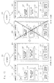
Fig. 2 . InFig. 2 , as for the transmission start information and the transmission completion information, "O" indicates that "thestandby system computer 130 received" and "X" indicates that "thestandby system computer 130 did not receive". Further, as for the first reliability guarantee information and the second reliability guarantee information, "O" indicates that "it is held to thestandby system computer 130 and "X" indicates that "it is not held to thestandby system computer 130". - As shown in
Fig. 2 , when thestandby system computer 130 has not received the transmission start information from the active system computer 110 (naturally the transmission completion information has not been received either), the first reliability guarantee information and the second reliability guarantee information is not held to thestandby system computer 130. This case is a case when the advance notice for giving the failure prediction in theactive system computer 110 is not received, for example when normal asynchronous replication is performed. - Meanwhile, when the
standby system computer 130 has received the transmission start information from theactive system computer 110 and not the transmission completion information, the first reliability guarantee information is held to thestandby system computer 130 but not the second reliability guarantee information. This case is a case when theactive system computer 110 has received the advance notice and performed the data transmission, which is to transmit the data not transmitted yet to the standby system computer 130 (hereinafter may be referred to as "data synchronization"), however the data synchronization has not been completely performed, for example when the failure occurred during the data synchronization. - Moreover, when the
standby system computer 130 has received both the transmission start information and the transmission completion information from theactive system computer 110, both the first reliability guarantee information and the second reliability guarantee information is held to thestandby system computer 130. This case is a case where the data synchronization is performed after theactive system computer 110 has received the advance notice, and this data synchronization is completely performed. - Therefore, when the
standby system computer 130 is switched to the active system computer to execute the business application, it is possible to confirm the reliability of the data backed up on thestorage device 132 of thestandby system computer 130 and take measures such as from where to execute the business application. - For example, in the
aforementioned case 2 where the "first reliability guarantee information" is held and the "second reliability guarantee information" is not held, it turns out that the data received before the transmission start information is reliable data and the business application can be executed from where the data is received last among the reliable data. - Further, in the
aforementioned case 3 where the "first reliability guarantee information" and the "second reliability guarantee information" is both held, it turns out that the data received before the transmission completion information is reliable data and the business application can be executed from where the data is received last among the reliable data. - Such a configuration of the
computer system 100 enables the asynchronous replication of the data between theactive system computer 110 and thestandby system computer 130 until the advance notice is received by theactive system computer 110. When the advance notice is received by theactive system computer 110, the data synchronization is performed between theactive system computer 110 and thestandby system computer 130 as well as the information of whether or not the data synchronization is complete, that is, how much of the data is reliable (the first reliability guarantee information and the second reliability guarantee information) is generated by and held to thestandby system computer 130. Therefore, while taking advantage of the asynchronous replication in the data replication, the reliability of the data backed up on the standby system computer can be guaranteed upon the failure. - Additionally, in the
computer system 100, theactive system computer 110 can reduce the amount of data transmitted to the receivingunit 120 by the above data synchronization and increase the probability of complete data synchronization by stopping the business application in execution. - Next, an exemplary embodiment embodying the aforementioned principle is explained.
Fig. 3 shows acomputer system 200 according to the exemplary embodiment of the present invention. Thecomputer system 200 includes a plurality of computers (in the drawing, only two of acomputer 210 and acomputer 220 are exemplified) and a failureprediction service device 240. These computers and the failureprediction service device 240 are connected via anetwork 230 such as LAN and WAN. - The plurality of computers included in the
computer system 200 of this exemplary embodiment have similar configurations. As shown inFig. 3 , thecomputer 210 is mounted with an operating system (hereinafter referred to as an OS) 214,replication software 216, and a business application (hereinafter referred to as AP)AP 218 and includes afirst storage device 212 to which the software reads and writes data and asecond storage device 213, which is different from thefirst storage device 212. Similarly, thecomputer 220 is mounted with anOS 224,replication software 226, and anAP 228, and includes afirst storage device 222 to which the software reads and writes data and asecond storage device 223, which is different from thefirst storage device 222. - In the example shown in
Fig. 3 , theAP 218 mounted on thecomputer 210 and theAP 228 mounted on thecomputer 220 are the same business applications, theAP 218 surrounded by the solid line frame is in execution, and theAP 228 surrounded by the dotted line frame is stopped. That is, in this case, thecomputer 210 is the active system computer and thecomputer 220 is the standby system computer. Moreover, data generated by executing theAP 218 is transmitted to and backed up on thecomputer 220 by the asynchronous replication. - The failure
prediction service device 240 transmits the advance notice for giving the failure prediction to the computer via thenetwork 230. In this exemplary embodiment, the failureprediction service device 240 is for giving a prediction of natural disasters such as earthquakes that could generate the failure in the computer and is installed in an organization and the like that predict the disasters, for example. - In the
computer system 200, the active system computer and the standby system computer usually perform the asynchronous data replication. This asynchronous replication is performed by the replication software mounted on the active system computer and the standby system computer. Upon receiving the advance notice, the active system computer stops the business application in execution as well as starts the data synchronization, and the standby system computer backs up the data transmitted from the active system computer in the data synchronization to its own storage device. -
Fig. 4 shows a specific configuration of each computer in thecomputer system 200. Note thatFig. 4 illustrates only the part relating to the aforementioned "data synchronization" and illustration and explanation of other parts is omitted. Additionally, in this exemplary embodiment, as each computer has the same configuration, thecomputer 210 is explained as a representative. - As shown in
Fig. 4 , thecomputer 210 includes thefirst storage device 212, thesecond storage device 213, atransceiver unit 300, acontrol unit 302, amain processing unit 310, an I/O request queue 312, atransmission queue 314, adecompression unit 316, acompression unit 318, and adifference storage unit 320. These functional blocks are realized by collaboration of hardware included in and software installed on thecomputer 210. - The
computer 210 can be any of the active system computer and the standby system computer. InFig. 4 , the solid lines between each functional block indicate flows of data and signals when thecomputer 210 is the active system computer, and the dotted lines indicate flows of data and signals when thecomputer 210 is the standby system computer. - The
main processing unit 310 includes a function to execute the business application and a backup function. When thecomputer 210 is the active system computer, the function to execute the business application is executed, and when thecomputer 210 is the standby system computer, the backup function is executed. That is, when thecomputer 210 is the active system computer, themain processing unit 310 can operate as an application execution unit, and when thecomputer 210 is the standby system computer, themain processing unit 310 can operate as a backup unit. - Hereinafter, an operation of each functional block in the
computer 210 is explained, separating the case of being active system computer and the case of being standby system computer. - In this case, the
main processing unit 310 queues the write data generated by executing the business application in the I/O request queue 312 and thetransmission queue 314. Upon queuing in thetransmission queue 314, while queuing temporary hold time information described later as additional time information together with the write data, the temporary hold time information is updated with this write time of occurrence (hereinafter referred to as write time). - A relationship between the write time of the data and the temporary hold time information is explained with reference to
Fig. 5 . As an example, writing of data 0,data 1,data 2, anddata 3 is generated in order of time, and assume that the write time of the data is respectively time 0,time 1,time 2, andtime 3. - The
main processing unit 310 holds the latest write time of occurrence as the temporary hold time information. As shown inFig. 5 , writing of data 0 is generated at the time 0, and the time 0 is saved as the temporary hold time information. - Next, since writing of the
data 1 is generated at thetime 1, the temporary hold time information is updated with thetime 1. - After that, the temporary hold time information is updated with the
time 2 when thedata 2 is written and updated with thetime 3 when thedata 3 is written. - When the
main processing unit 115 queues the write data in thetransmission queue 314, the temporary hold time information before update is associated with the data to be queued. This is explained with reference toFig. 6 . - The temporary hold time information being held is the write time of the data 0 (time 0) immediately before the write time of the data 1 (time 1). Therefore, at the
time 1, thedata 1 is queued in thetransmission queue 314 together with additional time information to be the time 0. Accordingly, the temporary hold time information is updated with thetime 1. - Similarly, as the temporary hold time information is the
time 1 immediately before the write time of the data 2 (time 2), at thetime 2, thedata 2 is queued in thetransmission queue 314 together with the additional time information to be thetime 1. Accordingly, the temporary hold time information is updated with thetime 2. - Moreover, since the temporary hold time information is the
time 2 immediately before the write time of the data 3 (time 3), at thetime 3, thedata 3 is queued in thetransmission queue 314 together with the additional time information to be thetime 2. Accordingly, the temporary hold time information is updated with thetime 3. - That is, in this exemplary embodiment, the write data and the write time of the previous write data is associated and queued in the
transmission queue 314. - The I/
O request queue 312 queues out the queued data sequentially to thefirst storage device 212. Thefirst storage device 212 stores the data from the I/O request queue 312. - Moreover, the
transmission queue 314 sequentially queues out the queued write data to thecompression unit 318. Thecompression unit 318 compresses the data from thetransmission queue 314 and outputs the data to thetransceiver unit 300. Thetransceiver unit 300 sequentially outputs the data from the compression unit 318 (hereinafter referred to as compressed data) to the standby system computer (thecomputer 220 in this case) via thenetwork 230. - Each aforementioned process is performed in accordance with an asynchronous replication rule for data, and detailed explanation is omitted here.
- Note that in the case of not being able to communicate with the standby system computer, the
main processing unit 310 does not queue the data in thetransmission queue 314 but stores the data to thedifference storage unit 320. After that, when communication can be made with the standby system computer, the data stored to thedifference storage unit 320 is queued in thetransmission queue 314. - As mentioned above, in this exemplary embodiment, the advance notice from the failure
prediction service device 240 is transmitted via thenetwork 230. That is, thetransceiver unit 300 of thecomputer 210 also serves as the receiving unit that receives this advance notice. - Upon the receipt of the advance notice, the
transceiver unit 300 notifies thecontrol 302 accordingly. - When the
control unit 302 is notified of the receipt of the advance notice from thecontrol unit 302, thecontrol unit 302 outputs a start instruction of the data synchronization to themain processing unit 310 as well as outputs a stop instruction of the business application asynchronously with the start instruction of the data synchronization. Outputting the start instruction of the data synchronization without waiting for the business application to stop enables instant start of the data synchronization process and instant notification of the first reliability guarantee information to the standby system. - Upon a receipt of the stop instruction of the business application, the
main processing unit 310 stops the business application. Then, there is no generation of new data by the business application. - Upon receiving the start instruction of the data synchronization, the
main processing unit 310 operates as follows. First, themain processing unit 310 interrupts the transmission data accumulated in thetransmission queue 314 and causes thetransceiver unit 300 to transmit the "synchronization start packet" indicating start of the data synchronization. The additional time information of the top queue of the data accumulated in thetransmission queue 314 is included in this synchronization start packet. This additional time information is the additional time information of the write data queued to the top of thetransmission queue 314, that is, the write time of the previous write data. - Then, the
transmission queue 314, thecompression unit 318, and thetransceiver unit 300 are controlled so that the write data accumulated in thetransmission queue 314 is sequentially transmitted after the aforementioned "synchronization start packet". - When all the data accumulated in the
transmission queue 314 is compressed and transmitted, themain processing unit 310 causes thetransceiver unit 300 to transmit the "synchronization completion packet" indicating completion of the data synchronization. This synchronization completion packet is the current temporary hold time information, that is, the write time of the last queue of the data accumulated in thetransmission queue 314. - In other words, upon the receipt of the advance notice that gives the failure prediction (disaster prediction in this exemplary embodiment) when the
computer 210 is the active system computer, the business application in execution is stopped in thecomputer 210 and also the synchronization start packet, the compressed data of the data queued in thetransmission queue 314, and the synchronization completion packet are transmitted from thecomputer 210. - In this case, the
transceiver unit 300 receives data from the active system computer along with the asynchronous replication of the data. This data is the compressed data of the data generated during execution in the active system computer. - The
main processing unit 310 causes thedecompression unit 316 to decompress the compressed data received by thetransceiver unit 300. Thedecompression unit 316 outputs the decompressed data to the I/O request queue 312. - The I/
O request queue 312 sequentially queues out the data from thedecompression unit 316 to thefirst storage device 212. Thefirst storage device 212 stores the data from the I/O request queue 312. - The aforementioned process is the process by the standby system computer side when the asynchronous replication of the data is executed, and detailed explanation is omitted here.
- When the
transceiver unit 300 receives the "synchronization start packet", themain processing unit 310 outputs the additional time information included in the synchronization start packet to the I/O request queue 312 as the first reliability guarantee information. Moreover, the I/O request queue 312 is controlled to queue out this additional time information to thesecond storage device 213. - Further, the
main processing unit 310 causes thedecompression unit 316 to sequentially decompress each data received by thetransceiver unit 300 after the "synchronization start packet" and output the data to the I/O request queue 312. Themain processing unit 310 controls the I/O request queue 312 to queue out this data to thefirst storage device 212. - Additionally, when the
transceiver unit 300 receives the "synchronization completion packet", themain processing unit 310 outputs the temporary hold time information included in the synchronization completion packet to the I/O request queue 312 as the second reliability guarantee information. Moreover, the I/O request queue 312 is controlled to queue out this temporary hold time information to thesecond storage device 213. - The meaning of the synchronization start packet, the synchronization completion packet, the first reliability guarantee information, the second reliability guarantee information in this exemplary embodiment is explained with reference to
Fig. 7 . In a similar manner as inFig. 2 , inFig. 7 , as for the synchronization start packet and the synchronization completion packet, "O" indicates that "the standby system computer received" and "X" indicates that "the standby system computer did not receive". Moreover, as for the first reliability guarantee information (the additional time information included in the synchronization start packet here) and the second reliability guarantee information (the temporary hold time information included in the synchronization completion packet here), "O" indicates that it is recorded on the storage device of the standby system computer" and "X" indicates that "it is not recorded on the storage device of the standby system computer". - As shown in
Fig. 7 , when the standby system computer has not received the synchronization start packet from the active system computer (naturally the synchronization completion packet has not been received either), the additional time information included in the synchronization start packet and the temporary hold time information included in the synchronization completion packet is not recorded on the second storage device of the standby system computer. This case is a case when the active system computer has not received the advance notice that gives the failure prediction, for example when normal asynchronous replication is performed. - On the other hand, when the standby system computer has received the synchronization start packet from the active system computer and has not received the synchronization completion packet, the additional time information included in the synchronization start packet is recorded on the second storage device of the standby system computer but not the temporary hold time information included in the synchronization completion packet. This case is a case when the active system computer has received the advance notice and performed data transmission, which is to transmit data not transmitted yet to the standby system computer (hereinafter may be referred to as "data synchronization"), however the data synchronization has not been completely performed, for example when the failure occurred during the data synchronization.
- Further, when the standby system computer has received both the synchronization start packet and the synchronization completion packet from the active system computer, both the additional time information included in the synchronization start packet and the temporary hold time information included in the synchronization completion packet is recorded on the second storage device of the standby system computer. This case is a case when the data synchronization is performed after the active system computer has received the advance notice, and this data synchronization is completely performed.
-
Fig. 8 is a flowchart showing a flow of the process in the active system computer in thecomputer system 200. - As shown in
Fig. 8 , the active system computer executes the business application as well as performs the asynchronous replication of the data generated by executing the business application with the standby system computer until receiving the advance notice (S100: No, S102). The asynchronous replication of the data in the step S102 is specifically a process to return the write control to the business application asynchronously with the process of transmitting the data to the standby system computer, compress the data accumulated in the transmission queue, and transmit the data to the standby system computer. - In the active system computer, upon the receipt of the advance notice, the control unit issues a stop instruction of the business application and a data synchronization start instruction (S110 and S120).
- Upon a receipt of the stop instruction of the business application, the main processing unit of the active system computer stops the business application in execution (S112).
- Moreover, upon a receipt of the start instruction of the data synchronization, the main processing unit of the active system computer causes the transceiver unit to transmit to the standby system computer the synchronization start packet including the additional time information of the top queue of the data accumulated in the transmission queue, and then compress and transmit the data accumulated in the transmission queue until the transmission queue is emptied (S124, S126: No, and after S124).
- When the compression and transmission of all data in the transmission queue is completed, the main processing unit causes the transmitting unit to transmit the synchronization completion packet including the temporary hold time information to the standby system computer.
-
Fig. 9 is a flowchart showing a flow of the process in the standby system computer in thecomputer system 200. - As shown in
Fig. 9 , the standby system computer backs up the data from the active system computer (compressed data) until receiving the synchronization start packet from the active system computer (S150: No and S 152). The backup in the step S152 is specifically the decompression of the compressed data from the active system computer, queuing in the I/O request queue, and queuing out from the I/O request queue to the first storage device. - Upon receiving the synchronization start packet, the main processing unit of the standby system computer records the additional time information included in the synchronization start packet on the second storage device as the first reliability guarantee information via the I/O request queue as well as backs up the compressed data from the active system computer and writes the compressed data to the first storage device until receiving the synchronization completion packet (S150: Yes, S160, S162:No, and after S164).
- Upon the receipt of the synchronization completion packet, the main processing unit of the standby system computer records the temporary hold time information included in the synchronization completion packet on the second storage device as the second reliability guarantee information via the I/O request queue (S162: Yes and S170).
-
Fig. 10 is an example of showing a manual or an automatic switch of the computer executing the business application after the failure occurred. -
Fig. 10 shows an example when the HA cluster software is mounted on each computer together with the replication software. The HA cluster software mounted on each computer monitors the state of each other's computer and exclusively executes the business application. The replication software performs the asynchronous data replication among the computer on which the business application is executed, the one on which the business application is mounted, and the computer not executed. The HA cluster software also switches the computer to execute the business application when the failure occurs in the computer on which the business application is executed. This switch can be selected in the setting either by automatically or manually. - As shown in
Fig. 10 , this example is an example of switching when thecomputer 210 is the active system computer and thecomputer 220 is the standby system computer. - After the failure occurs, the
computer 210, which has been the active system, is stopped. TheHA cluster software 227 in thecomputer 220 executes theAP 228. Then, thecomputer 220, which has been the standby system, is switched to the active system. Note that upon execution of theAP 228, theHA cluster software 227 checks whether the additional time information included in the synchronization start packet and the temporary hold time information included in the synchronization completion packet is recorded on thesecond storage device 223 of thecomputer 220 and determines an execution start point of theAP 228 based on the checked result. - Specifically, when only the additional time information included in the synchronization start packet is recorded on the
second storage device 223, theHA cluster software 227 executes theAP 228 at the point when the last data is obtained among the data transmitted and received before the transmission time, which is reliable data stored to thefirst storage device 222. Meanwhile, when the additional time information included in the synchronization start packet and the temporary hold time information included in the synchronization completion packet is both recorded on thesecond storage device 223, theHA cluster software 227 executes theAP 228 at the point when the last data is obtained among the data received before the synchronization completion packet, which is reliable data stored to thefirst storage device 222. - The
computer system 200 of this exemplary embodiment is an example of embodying the computer system shown inFig. 1 , and each effect of thecomputer system 100 can be achieved. - Further, in the
computer system 200, as the data is compressed to be transmitted between the active system computer and the standby system computer, the amount of data flowing through thenetwork 230 can be reduced. - Furthermore, recording the first reliability guarantee information and the second reliability guarantee information on the second storage device, which is different from the first storage device, enables the standby system computer to match the data in the first storage device of the active system computer and the standby system computer.
- The present invention has been explained based on the exemplary embodiments so far. The exemplary embodiments are examples and various modifications, additions, subtractions, and combinations can be made to each of the above exemplary embodiments without departing from the scope of the present invention. The person skilled in the art would understand that variations including these modifications, additions, subtractions, and combinations are in the scope of the present invention.
- For example, in the
computer system 200, both functions of the active system computer and the standby system computer are mounted on each computer. However, both of the aforementioned functions may be mounted only on the computer to be a server, for example. Moreover, in this case, only the function of the active system computer may be mounted on the active system server and only the function of the standby system computer may be mounted on the standby system server. - Further, operations can be carried out in a way that the function of the active system computer is mounted on an active system shared storage device and also the function of the standby computer is mounted on a standby system shared storage.
- Furthermore, although the
computer system 200 is explained to receive the advance notice via the network, the advance notice may be received by any communication system such as wireless radio as long as the advance notice can be received. - The present application claims priority rights of and is based on Japanese Patent Application No.
2010-050784 filed on March 8, 2010 - The present invention can be used for backup of data in a computer system that replicates data, especially in an asynchronous method.
-
- 100
COMPUTER SYSTEM 110 ACTIVE SYSTEM COMPUTER - 112
STORAGE DEVICE 114 APPLICATION EXECUTION UNIT - 115
MAIN PROCESSING UNIT 116 TRANSMITTING UNIT - 118
TRANSMISSION QUEUE 120 RECEIVING UNIT - 122
CONTROL UNIT 130 STANDBY SYSTEM COMPUTER - 132
STORAGE DEVICE 140 BACKUP UNIT - 200
COMPUTER SYSTEM 210 COMPUTER - 212
FIRST STORAGE DEVICE 213 SECOND STORAGE DEVICE - 214
OS 216 REPLICATION SOFTWARE - 217
HA CLUSTER SOFTWARE 218 APPLICATION - 220
COMPUTER 222 FIRST STORAGE DEVICE - 223
SECOND STORAGE DEVICE 224 OS - 226
REPLICATION SOFTWARE 227 HA CLUSTER SOFTWARE - 228
APPLICATION 230 NETWORK - 240 FAILURE
PREDICTION SERVICE DEVICE 300 TRANSCEIVER UNIT - 302
CONTROL UNIT 310 MAIN PROCESSING UNIT - 312 I/
O REQUEST QUEUE 314 TRANSMISSION QUEUE - 316
DECOMPRESSION UNIT 318 COMPRESSION UNIT - 320 DIFFERENCE STORAGE UNIT
Claims (9)
- A computer system comprising:an active system computer on which a business application is executed; anda standby system computer on which asynchronous replication of data is performed with the active system computer, the data being generated by executing the business application on the active system computer, whereinthe active system computer comprises:a storage device for the business application to write data in;a transmission queue that queues the data not transmitted yet to the standby system computer among the data written to the storage device by the business application;receiving means that receives an advance notice for giving a failure prediction;control means that stops the execution of the business application when the receiving means receives the advance notice; andtransmitting means that transmits to the standby system computer transmission start information indicating start of data transmission for failure avoidance, the data queued in the transmission queue, and transmission completion information indicating completion of the data transmission in this order when the receiving means receives the advance notice,the standby system computer comprises:a storage device; andbackup means that writes the data from the active system computer to the storage device along with the asynchronous replication, andthe backup means,upon a receipt of the transmission start information, writes the data received after the transmission start information to the storage device as well as generates and holds first reliability guarantee information indicating that the data received before the transmission start information is reliable data, andupon a receipt of the transmission completion information, generates and holds second reliability information indicating that the data received before the transmission completion information is reliable data.
- The computer according to Claim 1, wherein
the transmission start information includes write time of previous data generated before the data queued on a top of the transmission queue in the active system computer,
the transmission completion information includes the write time of the data queued at an end of the transmission queue, and
the backup means in the standby system computer holds the write time included in the transmission start information and the transmission completion information respectively as the first reliability guarantee information and the second reliability guarantee information. - An active system computer on which a business application is executed and asynchronous replication of data generated by executing the business application is performed with a standby system computer, the active system computer comprising:a storage device for the business application to write data in;a transmission queue that queues the data not transmitted yet to the standby system computer among the data written to the storage device by the business application;receiving means that receives an advance notice for giving a failure prediction;control means that stops the execution of the business application when the receiving means receives the advance notice; andtransmitting means that transmits to the standby system computer transmission start information indicating start of data transmission for failure avoidance, the data queued in the transmission queue, and transmission completion information indicating completion of the data transmission in this order when the receiving means receives the advance notice.
- The active system computer according to Claim 3, wherein the transmission start information includes write time of previous data generated before the data queued on a top of the transmission queue, and
the transmission completion information includes the write time of the data queued at an end of the transmission queue. - A standby system computer on which asynchronous replication of data is performed with an active system computer, the data being generated by executing a business application on the active system computer, the standby system computer comprising:a storage device; andbackup means that writes the data from the active system computer to the storage device along with the asynchronous replication, whereinthe backup means,upon a receipt of transmission start information from the active system computer, the transmission start information indicating start of data transmission performed for failure avoidance when the active system computer receives an advance notice for giving a failure prediction and also transmission of the data not transmitted yet to the standby system computer, writes the data received after the transmission start information to the storage device as well as generates and holds first reliability guarantee information indicating that the data received before the transmission start information is reliable data, andwhen the active system computer receives transmission completion information to be transmitted after completing the data completion, generates and holds second reliability information indicating that the data received before the transmission completion information is reliable data.
- The active system computer according to Claim 2, whereinthe transmission start information includes write time of previous data generated before the data queued on a top of the transmission queue, andthe transmission completion information includes the write time of the data queued at an end of the transmission queue.The standby system computer according to Claim 5,wherein the backup means holds the write time included in the transmission start information and the transmission completion information respectively as the first reliability guarantee information and the second reliability guarantee information.
- The standby system computer according to Claim 5 or 6, further comprising another storage device different from the storage device, wherein the backup means holds the first reliability guarantee information and the second reliability guarantee information by writing to the another storage device.
- A non-transitory computer readable medium storing a program that causes to an active system computer, on which a business application is executed, that can receive an advance notice for giving a failure prediction, and asynchronous replication of data generated by executing the business application is performed with a stand by system computer, to execute a process comprising:upon a receipt of the advance notice,stopping the execution of the business application; andtransmitting to the standby system computer transmission start information indicating start of data transmission for failure avoidance, data not transmitted yet to the standby system computer among data stored to a storage device by the business application, and transmission completion information indicating completion of the data transmission in this order.
- A non-transitory computer readable medium storing a program that causes a standby system computer, on which asynchronous replication of data generated by executing a business application on an active system computer is performed with the active system computer, to execute a process comprising:upon a receipt of transmission start information from the active system computer, the transmission start information indicating start of data transmission performed for failure avoidance when the active system computer receives an advance notice for giving a failure prediction and also transmission of the data not transmitted yet to the standby system computer,writing the data received after the transmission start information to the storage device; andgenerating and holding first reliability guarantee information indicating that the data received before the transmission start information is reliable data, andwhen the active system computer receives transmission completion information to be transmitted after completing the data completion, generating and holding second reliability information indicating that the data received before the transmission completion information is reliable data.
Applications Claiming Priority (2)
| Application Number | Priority Date | Filing Date | Title |
|---|---|---|---|
| JP2010050784 | 2010-03-08 | ||
| PCT/JP2010/006095 WO2011111131A1 (en) | 2010-03-08 | 2010-10-13 | Computer system, working computer and backup computer |
Publications (3)
| Publication Number | Publication Date |
|---|---|
| EP2546753A1 true EP2546753A1 (en) | 2013-01-16 |
| EP2546753A4 EP2546753A4 (en) | 2013-08-28 |
| EP2546753B1 EP2546753B1 (en) | 2015-04-08 |
Family
ID=44562979
Family Applications (1)
| Application Number | Title | Priority Date | Filing Date |
|---|---|---|---|
| EP20100847364 Not-in-force EP2546753B1 (en) | 2010-03-08 | 2010-10-13 | Computer system, active system computer and standby system computer |
Country Status (5)
| Country | Link |
|---|---|
| US (1) | US9128903B2 (en) |
| EP (1) | EP2546753B1 (en) |
| JP (1) | JP5459389B2 (en) |
| CN (1) | CN102792287B (en) |
| WO (1) | WO2011111131A1 (en) |
Families Citing this family (4)
| Publication number | Priority date | Publication date | Assignee | Title |
|---|---|---|---|---|
| GB2537486A (en) * | 2013-10-11 | 2016-10-19 | Landmark Graphics Corp | Automated workflow capture for analysis and error reporting in a drilling application |
| US10587688B2 (en) * | 2014-09-19 | 2020-03-10 | Netapp, Inc. | Techniques for coordinating parallel performance and cancellation of commands in a storage cluster system |
| CN104216803A (en) * | 2014-09-29 | 2014-12-17 | 北京奇艺世纪科技有限公司 | Data backup method and device for out-of-service nodes |
| CN115037674B (en) * | 2022-05-16 | 2023-08-22 | 郑州小鸟信息科技有限公司 | Single-machine and multi-equipment redundancy backup method for central control system |
Citations (4)
| Publication number | Priority date | Publication date | Assignee | Title |
|---|---|---|---|---|
| US6684306B1 (en) * | 1999-12-16 | 2004-01-27 | Hitachi, Ltd. | Data backup in presence of pending hazard |
| EP1562117A2 (en) * | 2004-02-03 | 2005-08-10 | Hitachi, Ltd. | Data restoration method using a log and corresponding storage subsystem |
| US7240238B2 (en) * | 1993-04-23 | 2007-07-03 | Emc Corporation | Remote data mirroring |
| US20070174484A1 (en) * | 2006-01-23 | 2007-07-26 | Stratus Technologies Bermuda Ltd. | Apparatus and method for high performance checkpointing and rollback of network operations |
Family Cites Families (35)
| Publication number | Priority date | Publication date | Assignee | Title |
|---|---|---|---|---|
| JP2001236258A (en) * | 1999-12-16 | 2001-08-31 | Hitachi Ltd | Storage controller |
| JP2002169738A (en) * | 2000-11-30 | 2002-06-14 | Mitsubishi Electric Corp | File distributing method |
| JP2002189570A (en) * | 2000-12-20 | 2002-07-05 | Hitachi Ltd | Duplex method for storage system, and storage system |
| US6948089B2 (en) * | 2002-01-10 | 2005-09-20 | Hitachi, Ltd. | Apparatus and method for multiple generation remote backup and fast restore |
| US7426559B2 (en) * | 2002-05-09 | 2008-09-16 | International Business Machines Corporation | Method for sequential coordination of external database application events with asynchronous internal database events |
| JP2004005066A (en) | 2002-05-30 | 2004-01-08 | Internatl Business Mach Corp <Ibm> | Backup technique of data recorded in two or more recording devices |
| JP2004326365A (en) | 2003-04-23 | 2004-11-18 | Alps Electric Co Ltd | Computer backup system |
| JP3930455B2 (en) | 2003-05-09 | 2007-06-13 | 株式会社東芝 | Computer system, service continuation control program |
| US7266665B2 (en) * | 2003-06-17 | 2007-09-04 | International Business Machines Corporation | Method, system, and article of manufacture for remote copying of data |
| US7801851B2 (en) * | 2003-06-30 | 2010-09-21 | Gravic, Inc. | Method for ensuring referential integrity in multi-threaded replication engines |
| JP4764596B2 (en) | 2003-12-08 | 2011-09-07 | 株式会社日立製作所 | Data transfer method and server computer |
| US7383463B2 (en) * | 2004-02-04 | 2008-06-03 | Emc Corporation | Internet protocol based disaster recovery of a server |
| JP4591840B2 (en) * | 2004-02-26 | 2010-12-01 | 日本電気株式会社 | Method of moving process between networks and network system thereof |
| US7490083B2 (en) * | 2004-02-27 | 2009-02-10 | International Business Machines Corporation | Parallel apply processing in data replication with preservation of transaction integrity and source ordering of dependent updates |
| JP2005292865A (en) * | 2004-03-31 | 2005-10-20 | Hitachi Ltd | Storage system and backup method for storage system |
| US7213103B2 (en) * | 2004-04-22 | 2007-05-01 | Apple Inc. | Accessing data storage systems without waiting for read errors |
| JP4721850B2 (en) | 2005-09-30 | 2011-07-13 | 三洋電機株式会社 | server |
| US7676702B2 (en) * | 2006-08-14 | 2010-03-09 | International Business Machines Corporation | Preemptive data protection for copy services in storage systems and applications |
| JP2008310517A (en) | 2007-06-13 | 2008-12-25 | Hitachi Ltd | Data identification method, data identification program, and active system device |
| US8131924B1 (en) * | 2008-03-19 | 2012-03-06 | Netapp, Inc. | De-duplication of data stored on tape media |
| US8234243B2 (en) * | 2008-06-19 | 2012-07-31 | Microsoft Corporation | Third tier transactional commit for asynchronous replication |
| JP2010050784A (en) | 2008-08-22 | 2010-03-04 | Nikon Corp | Digital camera |
| US8499297B2 (en) * | 2008-10-28 | 2013-07-30 | Vmware, Inc. | Low overhead fault tolerance through hybrid checkpointing and replay |
| US8266107B2 (en) * | 2009-03-11 | 2012-09-11 | International Business Machines Corporation | Method for mirroring a log file by threshold driven synchronization |
| US20100287407A1 (en) * | 2009-05-05 | 2010-11-11 | Siemens Medical Solutions Usa, Inc. | Computer Storage Synchronization and Backup System |
| US8930527B2 (en) * | 2009-05-26 | 2015-01-06 | Oracle International Corporation | High availability enabler |
| US8140914B2 (en) * | 2009-06-15 | 2012-03-20 | Microsoft Corporation | Failure-model-driven repair and backup |
| KR101265388B1 (en) * | 2009-07-02 | 2013-05-20 | 엔에이치엔비즈니스플랫폼 주식회사 | High Availability Data Base Management System and Method for Managing Database Using High Availability Data Base Management System |
| JP2013501293A (en) * | 2009-08-04 | 2013-01-10 | アクサナ・(イスラエル)・リミテッド | Data gap management in remote data mirroring system |
| US8285956B2 (en) * | 2009-10-22 | 2012-10-09 | Symantec Corporation | Efficient logging for asynchronously replicating volume groups |
| US8448014B2 (en) * | 2010-04-23 | 2013-05-21 | International Business Machines Corporation | Self-healing failover using a repository and dependency management system |
| US8484503B2 (en) * | 2010-08-18 | 2013-07-09 | International Business Machines Corporation | Disaster recovery replication throttling in deduplication systems |
| US8406233B2 (en) * | 2010-09-07 | 2013-03-26 | Check Point Software Technologies Ltd. | Predictive synchronization for clustered devices |
| US8667236B2 (en) * | 2010-09-29 | 2014-03-04 | Hewlett-Packard Development Company, L.P. | Host based write ordering for asynchronous replication |
| US9864772B2 (en) * | 2010-09-30 | 2018-01-09 | International Business Machines Corporation | Log-shipping data replication with early log record fetching |
-
2010
- 2010-10-13 JP JP2012504164A patent/JP5459389B2/en not_active Expired - Fee Related
- 2010-10-13 US US13/578,889 patent/US9128903B2/en not_active Expired - Fee Related
- 2010-10-13 CN CN201080065267.9A patent/CN102792287B/en not_active Expired - Fee Related
- 2010-10-13 EP EP20100847364 patent/EP2546753B1/en not_active Not-in-force
- 2010-10-13 WO PCT/JP2010/006095 patent/WO2011111131A1/en active Application Filing
Patent Citations (4)
| Publication number | Priority date | Publication date | Assignee | Title |
|---|---|---|---|---|
| US7240238B2 (en) * | 1993-04-23 | 2007-07-03 | Emc Corporation | Remote data mirroring |
| US6684306B1 (en) * | 1999-12-16 | 2004-01-27 | Hitachi, Ltd. | Data backup in presence of pending hazard |
| EP1562117A2 (en) * | 2004-02-03 | 2005-08-10 | Hitachi, Ltd. | Data restoration method using a log and corresponding storage subsystem |
| US20070174484A1 (en) * | 2006-01-23 | 2007-07-26 | Stratus Technologies Bermuda Ltd. | Apparatus and method for high performance checkpointing and rollback of network operations |
Non-Patent Citations (1)
| Title |
|---|
| See also references of WO2011111131A1 * |
Also Published As
| Publication number | Publication date |
|---|---|
| EP2546753A4 (en) | 2013-08-28 |
| JPWO2011111131A1 (en) | 2013-06-27 |
| US9128903B2 (en) | 2015-09-08 |
| EP2546753B1 (en) | 2015-04-08 |
| CN102792287B (en) | 2016-01-06 |
| JP5459389B2 (en) | 2014-04-02 |
| US20120324300A1 (en) | 2012-12-20 |
| CN102792287A (en) | 2012-11-21 |
| WO2011111131A1 (en) | 2011-09-15 |
Similar Documents
| Publication | Publication Date | Title |
|---|---|---|
| EP1771789B1 (en) | Method of improving replica server performance and a replica server system | |
| US7793060B2 (en) | System method and circuit for differential mirroring of data | |
| US7694177B2 (en) | Method and system for resynchronizing data between a primary and mirror data storage system | |
| US20100042795A1 (en) | Storage system, storage apparatus, and remote copy method | |
| US8005799B2 (en) | Information management system | |
| US20150067387A1 (en) | Method and apparatus for data storage | |
| EP2546753B1 (en) | Computer system, active system computer and standby system computer | |
| CN105159795A (en) | Data synchronization method, apparatus and system | |
| US7797571B2 (en) | System, method and circuit for mirroring data | |
| CN111190766A (en) | HBase database-based cross-machine-room cluster disaster recovery method, device and system | |
| CN106815094B (en) | Method and equipment for realizing transaction submission in master-slave synchronization mode | |
| US8880552B2 (en) | Database system and database control method | |
| US20150370648A1 (en) | Redundant system and redundancy method | |
| CN114138838A (en) | Data processing method and device, equipment and medium | |
| JP2009080705A (en) | Virtual machine system and method for restoring virtual machine in the system | |
| KR20170045981A (en) | System including a software and non-stop upgrading method of running software | |
| US8977897B2 (en) | Computer-readable recording medium, data management method, and storage device | |
| CN115934742A (en) | Fault processing method, device, equipment and storage medium | |
| US9971654B2 (en) | Safe storing data for disaster recovery | |
| US11386043B2 (en) | Method, device, and computer program product for managing snapshot in application environment | |
| US20150370664A1 (en) | Redundant system and redundancy method | |
| CN110609764B (en) | Method, apparatus and computer program product for data backup | |
| US20190324869A1 (en) | Method, device and computer readable medium for data synchronization | |
| JP2003036210A (en) | Agent program monitoring method, agent program monitoring system and agent monitoring program | |
| JP2008310517A (en) | Data identification method, data identification program, and active system device |
Legal Events
| Date | Code | Title | Description |
|---|---|---|---|
| PUAI | Public reference made under article 153(3) epc to a published international application that has entered the european phase |
Free format text: ORIGINAL CODE: 0009012 |
|
| 17P | Request for examination filed |
Effective date: 20120905 |
|
| AK | Designated contracting states |
Kind code of ref document: A1 Designated state(s): AL AT BE BG CH CY CZ DE DK EE ES FI FR GB GR HR HU IE IS IT LI LT LU LV MC MK MT NL NO PL PT RO RS SE SI SK SM TR |
|
| DAX | Request for extension of the european patent (deleted) | ||
| A4 | Supplementary search report drawn up and despatched |
Effective date: 20130730 |
|
| RIC1 | Information provided on ipc code assigned before grant |
Ipc: G06F 12/00 20060101ALI20130724BHEP Ipc: G06F 11/20 20060101ALI20130724BHEP Ipc: G06F 13/00 20060101AFI20130724BHEP Ipc: G06F 3/06 20060101ALI20130724BHEP |
|
| REG | Reference to a national code |
Ref country code: DE Ref legal event code: R079 Ref document number: 602010023884 Country of ref document: DE Free format text: PREVIOUS MAIN CLASS: G06F0013000000 Ipc: G06F0011160000 |
|
| RIC1 | Information provided on ipc code assigned before grant |
Ipc: G06F 11/16 20060101AFI20140515BHEP Ipc: G06F 11/20 20060101ALI20140515BHEP |
|
| GRAP | Despatch of communication of intention to grant a patent |
Free format text: ORIGINAL CODE: EPIDOSNIGR1 |
|
| INTG | Intention to grant announced |
Effective date: 20140708 |
|
| GRAS | Grant fee paid |
Free format text: ORIGINAL CODE: EPIDOSNIGR3 |
|
| GRAP | Despatch of communication of intention to grant a patent |
Free format text: ORIGINAL CODE: EPIDOSNIGR1 |
|
| INTG | Intention to grant announced |
Effective date: 20150202 |
|
| GRAA | (expected) grant |
Free format text: ORIGINAL CODE: 0009210 |
|
| AK | Designated contracting states |
Kind code of ref document: B1 Designated state(s): AL AT BE BG CH CY CZ DE DK EE ES FI FR GB GR HR HU IE IS IT LI LT LU LV MC MK MT NL NO PL PT RO RS SE SI SK SM TR |
|
| REG | Reference to a national code |
Ref country code: GB Ref legal event code: FG4D |
|
| REG | Reference to a national code |
Ref country code: CH Ref legal event code: EP |
|
| REG | Reference to a national code |
Ref country code: IE Ref legal event code: FG4D |
|
| REG | Reference to a national code |
Ref country code: AT Ref legal event code: REF Ref document number: 721019 Country of ref document: AT Kind code of ref document: T Effective date: 20150515 |
|
| REG | Reference to a national code |
Ref country code: DE Ref legal event code: R096 Ref document number: 602010023884 Country of ref document: DE Effective date: 20150521 |
|
| REG | Reference to a national code |
Ref country code: AT Ref legal event code: MK05 Ref document number: 721019 Country of ref document: AT Kind code of ref document: T Effective date: 20150408 |
|
| REG | Reference to a national code |
Ref country code: NL Ref legal event code: VDEP Effective date: 20150408 |
|
| REG | Reference to a national code |
Ref country code: LT Ref legal event code: MG4D |
|
| PG25 | Lapsed in a contracting state [announced via postgrant information from national office to epo] |
Ref country code: NL Free format text: LAPSE BECAUSE OF FAILURE TO SUBMIT A TRANSLATION OF THE DESCRIPTION OR TO PAY THE FEE WITHIN THE PRESCRIBED TIME-LIMIT Effective date: 20150408 |
|
| PG25 | Lapsed in a contracting state [announced via postgrant information from national office to epo] |
Ref country code: LT Free format text: LAPSE BECAUSE OF FAILURE TO SUBMIT A TRANSLATION OF THE DESCRIPTION OR TO PAY THE FEE WITHIN THE PRESCRIBED TIME-LIMIT Effective date: 20150408 Ref country code: ES Free format text: LAPSE BECAUSE OF FAILURE TO SUBMIT A TRANSLATION OF THE DESCRIPTION OR TO PAY THE FEE WITHIN THE PRESCRIBED TIME-LIMIT Effective date: 20150408 Ref country code: FI Free format text: LAPSE BECAUSE OF FAILURE TO SUBMIT A TRANSLATION OF THE DESCRIPTION OR TO PAY THE FEE WITHIN THE PRESCRIBED TIME-LIMIT Effective date: 20150408 Ref country code: HR Free format text: LAPSE BECAUSE OF FAILURE TO SUBMIT A TRANSLATION OF THE DESCRIPTION OR TO PAY THE FEE WITHIN THE PRESCRIBED TIME-LIMIT Effective date: 20150408 Ref country code: PT Free format text: LAPSE BECAUSE OF FAILURE TO SUBMIT A TRANSLATION OF THE DESCRIPTION OR TO PAY THE FEE WITHIN THE PRESCRIBED TIME-LIMIT Effective date: 20150810 Ref country code: NO Free format text: LAPSE BECAUSE OF FAILURE TO SUBMIT A TRANSLATION OF THE DESCRIPTION OR TO PAY THE FEE WITHIN THE PRESCRIBED TIME-LIMIT Effective date: 20150708 |
|
| REG | Reference to a national code |
Ref country code: FR Ref legal event code: PLFP Year of fee payment: 6 |
|
| PG25 | Lapsed in a contracting state [announced via postgrant information from national office to epo] |
Ref country code: RS Free format text: LAPSE BECAUSE OF FAILURE TO SUBMIT A TRANSLATION OF THE DESCRIPTION OR TO PAY THE FEE WITHIN THE PRESCRIBED TIME-LIMIT Effective date: 20150408 Ref country code: GR Free format text: LAPSE BECAUSE OF FAILURE TO SUBMIT A TRANSLATION OF THE DESCRIPTION OR TO PAY THE FEE WITHIN THE PRESCRIBED TIME-LIMIT Effective date: 20150709 Ref country code: AT Free format text: LAPSE BECAUSE OF FAILURE TO SUBMIT A TRANSLATION OF THE DESCRIPTION OR TO PAY THE FEE WITHIN THE PRESCRIBED TIME-LIMIT Effective date: 20150408 Ref country code: IS Free format text: LAPSE BECAUSE OF FAILURE TO SUBMIT A TRANSLATION OF THE DESCRIPTION OR TO PAY THE FEE WITHIN THE PRESCRIBED TIME-LIMIT Effective date: 20150808 Ref country code: LV Free format text: LAPSE BECAUSE OF FAILURE TO SUBMIT A TRANSLATION OF THE DESCRIPTION OR TO PAY THE FEE WITHIN THE PRESCRIBED TIME-LIMIT Effective date: 20150408 |
|
| REG | Reference to a national code |
Ref country code: DE Ref legal event code: R097 Ref document number: 602010023884 Country of ref document: DE |
|
| PG25 | Lapsed in a contracting state [announced via postgrant information from national office to epo] |
Ref country code: DK Free format text: LAPSE BECAUSE OF FAILURE TO SUBMIT A TRANSLATION OF THE DESCRIPTION OR TO PAY THE FEE WITHIN THE PRESCRIBED TIME-LIMIT Effective date: 20150408 Ref country code: EE Free format text: LAPSE BECAUSE OF FAILURE TO SUBMIT A TRANSLATION OF THE DESCRIPTION OR TO PAY THE FEE WITHIN THE PRESCRIBED TIME-LIMIT Effective date: 20150408 |
|
| PLBE | No opposition filed within time limit |
Free format text: ORIGINAL CODE: 0009261 |
|
| STAA | Information on the status of an ep patent application or granted ep patent |
Free format text: STATUS: NO OPPOSITION FILED WITHIN TIME LIMIT |
|
| PG25 | Lapsed in a contracting state [announced via postgrant information from national office to epo] |
Ref country code: SK Free format text: LAPSE BECAUSE OF FAILURE TO SUBMIT A TRANSLATION OF THE DESCRIPTION OR TO PAY THE FEE WITHIN THE PRESCRIBED TIME-LIMIT Effective date: 20150408 Ref country code: RO Free format text: LAPSE BECAUSE OF NON-PAYMENT OF DUE FEES Effective date: 20150408 Ref country code: PL Free format text: LAPSE BECAUSE OF FAILURE TO SUBMIT A TRANSLATION OF THE DESCRIPTION OR TO PAY THE FEE WITHIN THE PRESCRIBED TIME-LIMIT Effective date: 20150408 Ref country code: CZ Free format text: LAPSE BECAUSE OF FAILURE TO SUBMIT A TRANSLATION OF THE DESCRIPTION OR TO PAY THE FEE WITHIN THE PRESCRIBED TIME-LIMIT Effective date: 20150408 |
|
| 26N | No opposition filed |
Effective date: 20160111 |
|
| PG25 | Lapsed in a contracting state [announced via postgrant information from national office to epo] |
Ref country code: IT Free format text: LAPSE BECAUSE OF FAILURE TO SUBMIT A TRANSLATION OF THE DESCRIPTION OR TO PAY THE FEE WITHIN THE PRESCRIBED TIME-LIMIT Effective date: 20150408 |
|
| PG25 | Lapsed in a contracting state [announced via postgrant information from national office to epo] |
Ref country code: SI Free format text: LAPSE BECAUSE OF FAILURE TO SUBMIT A TRANSLATION OF THE DESCRIPTION OR TO PAY THE FEE WITHIN THE PRESCRIBED TIME-LIMIT Effective date: 20150408 Ref country code: LU Free format text: LAPSE BECAUSE OF FAILURE TO SUBMIT A TRANSLATION OF THE DESCRIPTION OR TO PAY THE FEE WITHIN THE PRESCRIBED TIME-LIMIT Effective date: 20151013 |
|
| REG | Reference to a national code |
Ref country code: CH Ref legal event code: PL |
|
| PG25 | Lapsed in a contracting state [announced via postgrant information from national office to epo] |
Ref country code: MC Free format text: LAPSE BECAUSE OF FAILURE TO SUBMIT A TRANSLATION OF THE DESCRIPTION OR TO PAY THE FEE WITHIN THE PRESCRIBED TIME-LIMIT Effective date: 20150408 |
|
| REG | Reference to a national code |
Ref country code: IE Ref legal event code: MM4A |
|
| PG25 | Lapsed in a contracting state [announced via postgrant information from national office to epo] |
Ref country code: LI Free format text: LAPSE BECAUSE OF NON-PAYMENT OF DUE FEES Effective date: 20151031 Ref country code: CH Free format text: LAPSE BECAUSE OF NON-PAYMENT OF DUE FEES Effective date: 20151031 |
|
| PG25 | Lapsed in a contracting state [announced via postgrant information from national office to epo] |
Ref country code: BE Free format text: LAPSE BECAUSE OF FAILURE TO SUBMIT A TRANSLATION OF THE DESCRIPTION OR TO PAY THE FEE WITHIN THE PRESCRIBED TIME-LIMIT Effective date: 20150408 |
|
| REG | Reference to a national code |
Ref country code: FR Ref legal event code: PLFP Year of fee payment: 7 |
|
| PG25 | Lapsed in a contracting state [announced via postgrant information from national office to epo] |
Ref country code: IE Free format text: LAPSE BECAUSE OF NON-PAYMENT OF DUE FEES Effective date: 20151013 |
|
| PG25 | Lapsed in a contracting state [announced via postgrant information from national office to epo] |
Ref country code: HU Free format text: LAPSE BECAUSE OF FAILURE TO SUBMIT A TRANSLATION OF THE DESCRIPTION OR TO PAY THE FEE WITHIN THE PRESCRIBED TIME-LIMIT; INVALID AB INITIO Effective date: 20101013 Ref country code: BG Free format text: LAPSE BECAUSE OF FAILURE TO SUBMIT A TRANSLATION OF THE DESCRIPTION OR TO PAY THE FEE WITHIN THE PRESCRIBED TIME-LIMIT Effective date: 20150408 Ref country code: SM Free format text: LAPSE BECAUSE OF FAILURE TO SUBMIT A TRANSLATION OF THE DESCRIPTION OR TO PAY THE FEE WITHIN THE PRESCRIBED TIME-LIMIT Effective date: 20150408 |
|
| PG25 | Lapsed in a contracting state [announced via postgrant information from national office to epo] |
Ref country code: CY Free format text: LAPSE BECAUSE OF FAILURE TO SUBMIT A TRANSLATION OF THE DESCRIPTION OR TO PAY THE FEE WITHIN THE PRESCRIBED TIME-LIMIT Effective date: 20150408 Ref country code: SE Free format text: LAPSE BECAUSE OF FAILURE TO SUBMIT A TRANSLATION OF THE DESCRIPTION OR TO PAY THE FEE WITHIN THE PRESCRIBED TIME-LIMIT Effective date: 20150408 |
|
| PG25 | Lapsed in a contracting state [announced via postgrant information from national office to epo] |
Ref country code: MT Free format text: LAPSE BECAUSE OF FAILURE TO SUBMIT A TRANSLATION OF THE DESCRIPTION OR TO PAY THE FEE WITHIN THE PRESCRIBED TIME-LIMIT Effective date: 20150408 |
|
| REG | Reference to a national code |
Ref country code: FR Ref legal event code: PLFP Year of fee payment: 8 |
|
| PG25 | Lapsed in a contracting state [announced via postgrant information from national office to epo] |
Ref country code: TR Free format text: LAPSE BECAUSE OF FAILURE TO SUBMIT A TRANSLATION OF THE DESCRIPTION OR TO PAY THE FEE WITHIN THE PRESCRIBED TIME-LIMIT Effective date: 20150408 Ref country code: MK Free format text: LAPSE BECAUSE OF FAILURE TO SUBMIT A TRANSLATION OF THE DESCRIPTION OR TO PAY THE FEE WITHIN THE PRESCRIBED TIME-LIMIT Effective date: 20150408 |
|
| REG | Reference to a national code |
Ref country code: FR Ref legal event code: PLFP Year of fee payment: 9 |
|
| PG25 | Lapsed in a contracting state [announced via postgrant information from national office to epo] |
Ref country code: AL Free format text: LAPSE BECAUSE OF FAILURE TO SUBMIT A TRANSLATION OF THE DESCRIPTION OR TO PAY THE FEE WITHIN THE PRESCRIBED TIME-LIMIT Effective date: 20150408 |
|
| PGFP | Annual fee paid to national office [announced via postgrant information from national office to epo] |
Ref country code: GB Payment date: 20200930 Year of fee payment: 11 Ref country code: FR Payment date: 20200914 Year of fee payment: 11 |
|
| PGFP | Annual fee paid to national office [announced via postgrant information from national office to epo] |
Ref country code: DE Payment date: 20200929 Year of fee payment: 11 |
|
| REG | Reference to a national code |
Ref country code: DE Ref legal event code: R119 Ref document number: 602010023884 Country of ref document: DE |
|
| GBPC | Gb: european patent ceased through non-payment of renewal fee |
Effective date: 20211013 |
|
| PG25 | Lapsed in a contracting state [announced via postgrant information from national office to epo] |
Ref country code: GB Free format text: LAPSE BECAUSE OF NON-PAYMENT OF DUE FEES Effective date: 20211013 Ref country code: DE Free format text: LAPSE BECAUSE OF NON-PAYMENT OF DUE FEES Effective date: 20220503 |
|
| PG25 | Lapsed in a contracting state [announced via postgrant information from national office to epo] |
Ref country code: FR Free format text: LAPSE BECAUSE OF NON-PAYMENT OF DUE FEES Effective date: 20211031 |