EP2546719A2 - Hinge for electronic device - Google Patents
Hinge for electronic device Download PDFInfo
- Publication number
- EP2546719A2 EP2546719A2 EP12164382A EP12164382A EP2546719A2 EP 2546719 A2 EP2546719 A2 EP 2546719A2 EP 12164382 A EP12164382 A EP 12164382A EP 12164382 A EP12164382 A EP 12164382A EP 2546719 A2 EP2546719 A2 EP 2546719A2
- Authority
- EP
- European Patent Office
- Prior art keywords
- pivot assembly
- gear
- cover
- base
- shaft
- Prior art date
- Legal status (The legal status is an assumption and is not a legal conclusion. Google has not performed a legal analysis and makes no representation as to the accuracy of the status listed.)
- Granted
Links
Images






Classifications
-
- F—MECHANICAL ENGINEERING; LIGHTING; HEATING; WEAPONS; BLASTING
- F16—ENGINEERING ELEMENTS AND UNITS; GENERAL MEASURES FOR PRODUCING AND MAINTAINING EFFECTIVE FUNCTIONING OF MACHINES OR INSTALLATIONS; THERMAL INSULATION IN GENERAL
- F16H—GEARING
- F16H19/00—Gearings comprising essentially only toothed gears or friction members and not capable of conveying indefinitely-continuing rotary motion
- F16H19/08—Gearings comprising essentially only toothed gears or friction members and not capable of conveying indefinitely-continuing rotary motion for interconverting rotary motion and oscillating motion
-
- G—PHYSICS
- G06—COMPUTING OR CALCULATING; COUNTING
- G06F—ELECTRIC DIGITAL DATA PROCESSING
- G06F1/00—Details not covered by groups G06F3/00 - G06F13/00 and G06F21/00
- G06F1/16—Constructional details or arrangements
- G06F1/1613—Constructional details or arrangements for portable computers
- G06F1/1633—Constructional details or arrangements of portable computers not specific to the type of enclosures covered by groups G06F1/1615 - G06F1/1626
- G06F1/1675—Miscellaneous details related to the relative movement between the different enclosures or enclosure parts
- G06F1/1681—Details related solely to hinges
-
- H—ELECTRICITY
- H04—ELECTRIC COMMUNICATION TECHNIQUE
- H04M—TELEPHONIC COMMUNICATION
- H04M1/00—Substation equipment, e.g. for use by subscribers
- H04M1/02—Constructional features of telephone sets
- H04M1/0202—Portable telephone sets, e.g. cordless phones, mobile phones or bar type handsets
- H04M1/0206—Portable telephones comprising a plurality of mechanically joined movable body parts, e.g. hinged housings
- H04M1/0208—Portable telephones comprising a plurality of mechanically joined movable body parts, e.g. hinged housings characterized by the relative motions of the body parts
- H04M1/0214—Foldable telephones, i.e. with body parts pivoting to an open position around an axis parallel to the plane they define in closed position
- H04M1/0216—Foldable in one direction, i.e. using a one degree of freedom hinge
- H04M1/022—The hinge comprising two parallel pivoting axes
-
- Y—GENERAL TAGGING OF NEW TECHNOLOGICAL DEVELOPMENTS; GENERAL TAGGING OF CROSS-SECTIONAL TECHNOLOGIES SPANNING OVER SEVERAL SECTIONS OF THE IPC; TECHNICAL SUBJECTS COVERED BY FORMER USPC CROSS-REFERENCE ART COLLECTIONS [XRACs] AND DIGESTS
- Y10—TECHNICAL SUBJECTS COVERED BY FORMER USPC
- Y10T—TECHNICAL SUBJECTS COVERED BY FORMER US CLASSIFICATION
- Y10T74/00—Machine element or mechanism
- Y10T74/18—Mechanical movements
- Y10T74/18856—Oscillating to oscillating
- Y10T74/1888—Geared connections
Definitions
- the invention relates to electronic equipment, and in particular to collapsible electronic equipment.
- Touch screens are wildly used in many kinds of electronic equipments, and thus notebooks with dual screens have been developed, recently.
- a keyboard is replaced by a touch screen.
- a user may control the notebook via the touch screen.
- the notebook may be used as a tablet personal computer when the cover of the notebook is opened at 180 degrees relative to the base of the notebook.
- a pivot assembly of a conventional notebook with a single screen has a retaining structure.
- the cover of the notebook can be tiltably kept in a predetermined position by the retaining structure.
- the cover cannot be opened at 180 degrees relative to the base of the notebook by the pivot assembly.
- the cover of the notebook When the pivot assembly is applied to a notebook with dual screens, the cover of the notebook may be opened at 180 degrees relative to the base by removing the retaining structure. However, when the notebook is opened at 180 degrees, the gap between the cover and the base is wide because of the structure of the pivot assembly.
- the display surfaces of the cover and the base are not located on the same plane, and thus display between the screens of the cover and the base are imperfect.
- the cover since the retaining structure of the pivot assembly is removed, the cover cannot be kept in a predetermined position when the cover is inclined relative to the base. Thus, the use of the notebook with dual screens is not convenient.
- the objective of the invention provides collapsible electronic equipment having a cover and a base.
- the cover is opened at 180 degrees relative to the base.
- the gap between the cover and the base is narrow, and the display surfaces of the cover and the base can be located on the same plane.
- the cover when the cover is inclined to a predetermined angle relative to the base, the cover may be kept at a predetermined position, and thus the use of the collapsible electronic equipment is convenient.
- a collapsible electronic equipment includes a base, a cover, and a pivot structure.
- the base has a first base side and a second base side close to the first base side.
- the cover has a first cover side and a second cover side.
- the first cover side is substantially parallel to the first base side and is close to the second cover side.
- the pivot structure includes a first pivot assembly, a second pivot assembly, and a gear mechanism.
- the first pivot assembly is disposed on the second base side.
- the second pivot assembly is disposed on the second cover side.
- the gear mechanism is connected to the first pivot assembly and the second pivot assembly.
- the cover is opened or closed relative to the base by the pivot structure.
- a pivot structure disposed on a collapsible electronic equipment includes a gear mechanism, a first pivot assembly, and a second pivot assembly.
- the gear mechanism has at least on connecting board and a gear set.
- the gear set includes a first gear, a plurality of transmitting gears and an end gear. The first gear, the transmitting gears, and the end gear are engaged in sequence.
- the first pivot assembly has a first shaft passing through the connecting board and the first gear.
- the second pivot assembly has a second shaft passing through the connecting board and the end gear.
- Fig. 1A is a perspective view of collapsible electronic equipment of the invention, wherein the cover is opened at 180 degrees relative to the base;
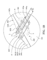
- Fig. 1B is an enlarged view of the part A of Fig. 1A ;
- Fig. 1C is a schematic view of the collapsible electronic equipment of the invention, wherein the cover is opened at 0 degree relative to the base;
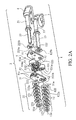
- Fig. 2A is an exploded view of a pivot structure of the invention
- Fig. 2B is a partial exploded view of the pivot structure of the invention.
- Fig. 3 is a perspective view of the pivot structure of the invention.
- Fig. 4 is another perspective view of the pivot structure of the invention.
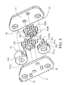
- Fig. 5 is an exploded view of the pivot structure of the invention.
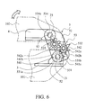
- Fig. 6 is a schematic view of the collapsible electronic equipment of the invention, wherein the cover is at 0 degree relative to the base;
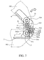
- Fig. 7 is a schematic view of the collapsible electronic equipment of the invention, wherein the cover is at 40 degrees relative to the base;
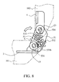
- Fig. 8 is a schematic view of the collapsible electronic equipment of the invention, wherein the cover is at 90 degrees relative to the base;
- Fig. 9 is a schematic view of the collapsible electronic equipment of the invention, wherein the cover is at 140 degrees relative to the base;
- Fig. 10 is a schematic view of the collapsible electronic equipment of the invention, wherein the cover is at 180 degrees relative to the base;
- Fig. 11 is a schematic view of the collapsible electronic equipment of the invention, wherein the cover is at 0 degree relative to the base.
- Fig. 1A is a perspective view of collapsible electronic equipment 100 of the invention.
- Fig. 1B is an enlarged view of the part A of Fig. 1A .
- the collapsible electronic equipment 100 may be a portable electronic equipment, such as a notebook or a mobile phone.
- the collapsible electronic equipment 100 includes two pivot structures 200, a base 101, a cover 102, a first display screen 103, a second display screen 104, and two pivot covers 105.
- the pivot structures 200 are respectively disposed on two opposite sides of the base 101 and the cover 102.
- the cover 102 is opened or closed relative to the base 101 by the pivot structure 200.
- the base 101 has a first base side 101a, a second base side 101b, and a first display surface 101c.
- the first base side 101a is close to the second base side 101b.
- the first base side 101a and the second base side 101b are adjacent to the first display surface 101c.
- the first base side 101a is substantially perpendicular to the second base side 101b.
- the cover 102 has a first cover side 102a, a second cover side 102b, and a second display surface 102c.
- the first cover side 102a is close to the second cover side 102b, and the first cover side 102a and the second cover side 102b are adjacent to the second display surface 102c.
- the first cover side 102a is substantially perpendicular to the second cover side 102b.
- the first cover side 102a faces the first base side 101a and is substantially parallel to the first base side 101a.
- the first display screen 103 is disposed on the first display surface 101c of the base 101, and the second display screen 104 is disposed on the second display surface 102c of the cover 102.
- the first display screen 103 and the second display screen 104 may be touch screens.
- the pivot structure 200 is connected to the second base side 101b of the base 101 and the second cover side 102b of the cover 102.
- the pivot structure 200 includes a first pivot assembly 1, a second pivot assembly 2, a bottom stand 3, a stand 4, and a gear mechanism 5.
- the first pivot assembly 1 is disposed on the second base side 101b and passes through the second base side 101b. Namely, an end of the first pivot assembly 1 is located inside the base 101, and the other end of the first pivot assembly 1 is located outside the base 101.
- the second pivot assembly 2 is disposed on the second cover side 102b and passes through the second cover side 102b. Namely, an end of the second pivot assembly 2 is located inside the cover 102, and the other end of the second pivot assembly 2 is located outside the cover 102.
- first pivot assembly 1 and the second pivot assembly 2 are substantially parallel to the first base side 101 a and the first cover side 102a, and are substantially perpendicular to the second base side 101b and the second cover side 102b.
- the bottom stand 3 is fixed within the base 101 and connected to the end of the first pivot assembly 1.
- the stand 4 is fixed within the cover 102 and connected to the end of the second pivot assembly 2.
- the gear mechanism 5 is disposed on the other ends of the first pivot assembly 1 and the second pivot assembly 2 and outside the base 101 and the cover 102.
- the base 101 has a first groove 101d disposed on the second base side 101b
- the cover 102 has a second groove 102d disposed on the second cover side 102b.
- the second groove 102d and the first groove 101d are communicated with each other.
- the other end of the first pivot assembly 1 is located within the first groove 101d
- the other end of the second pivot assembly 2 is located within the second groove 102d.
- the gear mechanism 5 is located within the first groove 101d and the second groove 102d.
- the pivot cover 105 is located within the first groove 101d and the second groove 102d and covers the other end of the first pivot assembly 1, the other end of the second pivot assembly 2, and the gear mechanisms 5.
- the cover 102 is opened or closed relative to the base 101 by the pivot structures 200. As shown in Figs. 1A and 1B , the cover 102 is at a completely opened status relative to the base 101. There is an opening angle A1 of 180 degrees between the cover 102 and the base 101. When the cover 102 is at the completely opened status, a user may use the collapsible electronic equipment 100 as a tablet personal computer. Further, as shown in Fig. 1C , the cover 102 covers the base 101 and is closed at a closed angle of 0 degree relative to and the base 101.
- the first display screen 103 and the second display screen 104 are located on the same plane, and the maximal length W1 of the gear mechanism 5 is longer than the shortest distance D1 between the first display screen 103 and the second display screen 104.
- the first display screen 103 is adjacent to an interface of the first base side 101 a and the first display surface 101 c.
- the second display screen 104 is adjacent to an interface of the first cover side 102a and the second display surface 102c.
- the gap between the first display screen 103 and the second display screen 104 is narrow.
- the first pivot assembly 1 has a first shaft 11 and a first torsion structure 12.
- the first shaft 11 is fixed on the bottom stand 3, and the first torsion structure 12 provides a first rotation torsion.
- the first shaft 11 has a first non-circular shaft 13.
- the second pivot assembly 2 has a second shaft 21 and a second torsion structure 22.
- the second shaft 21 is fixed on the stand 4, and the second torsion structure 22 provides a second rotation torsion greater than the first rotation torsion.
- the second shaft 21 has a second non-circular shaft 23.
- the first shaft 11 is substantially parallel to the second shaft 21.
- the gear mechanism 5 has two connecting boards 51 and a gear set 53.
- Each of the connecting boards 51 has two circular holes 52.
- the first non-circular shaft 13 of the first shaft 11 and the second non-circular shaft 23 of the second shaft 21 pass through the circular holes 52, respectively.
- the gear set 53 is located between the connecting boards 51.
- the gear set 53 has a first gear 531, a first transmitting gear 532, a second transmitting gear 533, and an end gear 534.
- the first gear 531 of the gear set 53 has a non-circular hole 531a, and the first non-circular shaft 13 passes through the non-circular hole 531a.
- the end gear 534 has a non-circular hole 534a, and the second non-circular shaft 23 passes through the non-circular hole 534a.
- the first transmitting gear 532 and the second transmitting gear 533 are disposed between the first gear 531and the end gear 534 of the gear set 53.
- the first transmitting gear 532 is engaged with the first gear 531 and the second transmitting gear 533.
- the second transmitting gear 533 is engaged with the end gear 534.
- the torsion structure 12 of the first pivot assembly 1 is disposed on the first non-circular shaft 13.
- the torsion structure 12 has a plurality of first disk-shaped elastic pieces 121, a first cam 122, a first retaining board 123, a first nut 124, and a first blocking strip 125.
- An end of the first non-circular shaft 13 is fastened by the first retaining board 123 and the first nut 124 to force the first disk-shaped elastic pieces 121 pressing the first cam 122.
- the first cam 122 has a non-circular hole 122a and a plurality of first projections 122b (shown in Fig. 2B ).
- the first non-circular shaft 13 passes through the non-circular hole 122a.
- the first projections 122b are disposed on the surface of the first cam 122.
- the projection 122b is received in a first recess 51a of the connecting board 51', which is adjacent to the projection 122b.
- the first blocking strip 125 is disposed on the outside of the connecting board 51 "(sub-connecting board), which is not adjacent to the first cam 122 of the first pivot assembly 1.
- the first blocking strip 125 has a non-circular hole 125a.
- the first non-circular shaft 13 passes through the non-circular hole 125a.
- the first blocking strip 125 has a sector-shaped portion 125b disposed an edge thereof.
- the sector-shaped portion 125b corresponds to a blocking lump 51 b extended from the connecting board 51" (as shown in Fig. 2B ) to limit the connecting board 51" rotating about the first shaft 11 in a rotation angle.
- the torsion structure 22 of the second pivot assembly 2 is disposed on the second non-circular shaft 23 of the second shaft 21.
- the torsion structure 22 has a plurality of second disk-shaped elastic pieces 221, a second cam 222, a second retaining board 223, a second nut 224, and a second blocking strip 225.
- the second cam 222 is pressed by the second disk-shaped elastic pieces 221.
- An end of the second non-circular shaft 23 is fastened by the second retaining board 223 and the second nut 224 to force the second disk-shaped elastic pieces 221 pressing the second cam 222.
- the second cam 222 has a non-circular hole 222a and a plurality of second projections 222b (shown in Fig. 2B ).
- the second non-circular shaft 23 passes through the non-circular hole 222a.
- the second projections 222b are disposed on the surface of the second cam 222.
- the projection 222b is received in the second recess 51c of an adjacent connecting board 51', which is adjacent to the projection 122b.
- the second blocking strip 225 is disposed on the outside of the connecting board 51", which is not adjacent to the second cam 222 of the second pivot assembly 2.
- the second blocking strip 225 has a non-circular hole 225a.
- the first non-circular shaft 23 passes through the non-circular hole 225a.
- the edge of the first non-circular shaft 23 has a sector-shaped portion 225b.
- the sector-shaped portion 225b corresponds to a blocking lump 51 d extended from the connecting board 51 "(as shown in Fig. 2B ) to limit the connecting board 51" rotating about the second shaft 21 in the rotation angle.
- the cover 102 can be rotated about the base 101 between the closed angle (0 degree) and the opening angle (180 degrees) to be opened or closed relative to the base 101 by the first pivot assembly 1 and the second pivot assembly 2 of the embodiment. Further, the cover 102 can be kept on a predetermined position at a predetermined angle. Namely, the stand 4 can be rotated about the bottom stand 3 between the closed angle and the opening angle by the first pivot assembly 1 and the second pivot assembly 2. Further, the stand 4 can be kept on the predetermined position at the predetermined angle.
- the connecting boards 51 are rotated about the first shaft 11 of the first pivot assembly 1 and the second shaft 21 of the second pivot assembly 2 at a specified angle between a first middle angle (such as 40 degrees) and a second middle angle (such as 140 degrees).
- the connecting boards 51 are rotated about the first shaft 11 and are not rotated about the second shaft 21 of the first pivot assembly 1 at a non-specified angle between 0 degree and 40 degrees or between 140 degrees and 180 degrees.
- FIG. 6 to Fig. 10 are schematic views of opening movements of the cover 102 between 0 degree and 180 degrees relative to the base 101, wherein closing movements of the cover 102 relative to the base 101 are the reversal of the opening movements.
- the A-shaped teeth portion 531b drives the first transmitting gear 532
- the first transmitting gear 532 drives the second transmitting gear 533
- the second transmitting gear 533 drives the end gear 534.
- the connecting board 51 may be rotated about 50 degrees about the first non-circular shaft 13 of the first shaft 11 of the first pivot assembly 1, and the connecting board 51 may be rotated about 50 degrees relative to the second non-circular shaft 23 of the second shaft 21 of the second pivot assembly 2.
- the pivot structure 200 of the embodiment has a function with intermittent transmission. Since the torsion of the second pivot assembly 2 is greater than the torsion of the first pivot assembly 1, the second pivot assembly 2 is not rotated and the first pivot assembly 1 with lower torsion is rotated when the cover is opened at the non-specified angle relative to the base 101. When the cover is opened at the specified angle between 40 degrees and 140 degrees relative to the base 101, the torsion is transmitted by the gear set 53 of the gear mechanism 5 to force the second pivot assembly 2 with greater torsion to rotate?. Thus, when the cover 102 is opened at 180 degrees relative to base 101, as shown in Fig. 1 , the gap between the cover 102 and the base 101 is narrow. The first display surface 101c of the base 101 and the second display screen 104 of the cover 102 are located on the same plane, and the collapsible electronic equipment 100 may be opened like a book.
- the first gear 531 has a first retaining cam 541 having a sector groove 541a.
- the A-shaped teeth portion 531b is located in the middle of the sector groove 541a.
- the first transmitting gear 532 has a second retaining cam 542 having two protrusions 542a.
- Each of the protrusions 542a has an arc surface 542b.
- the cover 102 and the stand 4 are rotated at a non-specified angle between 0 degree and 40 degrees or between 140 degrees and 180 degrees relative to the base 101 and the bottom stand 3, the arc surfaces 542b of the protrusions 542a are close to the circumference of the first retaining cam 541 outside of the sector groove 541a.
- the first retaining cam 541 and the second retaining cam 542 are formed as a retaining mechanism.
- the cover 102 is at the non-specified angle between 0 degree and 40 degrees or between 140 degrees and 180 degrees relative to the base 101, the arc surfaces 542b of the protrusions 542a are close to the circumference of the first retaining cam 541 outside of the sector groove 541a.
- the gear set 53 can not be driven when the cover 102 is at the non-specified angle relative to the base 101, and thus the collapsible electronic equipment 100 can be prevented from being opened.
- the cover of the collapsible electronic equipment can be opened at 180 degrees relative to the base, and the gap between the cover and the base is narrow. Moreover, the display surfaces of the cover and the base are located on the same horizontal plane, and thus the displays of the display screens of the cover and the base is greater. Further, when the cover is inclined to a predetermined angle relative to the base, the cover is kept at a predetermined position. Thus, the use of the collapsible electronic equipment is convenient.
Landscapes
- Engineering & Computer Science (AREA)
- General Engineering & Computer Science (AREA)
- Computer Hardware Design (AREA)
- Theoretical Computer Science (AREA)
- Human Computer Interaction (AREA)
- Physics & Mathematics (AREA)
- General Physics & Mathematics (AREA)
- Signal Processing (AREA)
- Mechanical Engineering (AREA)
- Pivots And Pivotal Connections (AREA)
- Telephone Set Structure (AREA)
Abstract
Description
- This Application claims priority of Taiwan Patent Application No.
100212810, filed on Jul. 13, 2011 - The invention relates to electronic equipment, and in particular to collapsible electronic equipment.
- Touch screens are wildly used in many kinds of electronic equipments, and thus notebooks with dual screens have been developed, recently. In the notebook, a keyboard is replaced by a touch screen. A user may control the notebook via the touch screen. Further, the notebook may be used as a tablet personal computer when the cover of the notebook is opened at 180 degrees relative to the base of the notebook.
- A pivot assembly of a conventional notebook with a single screen has a retaining structure. Thus, when the notebook is opened, the cover of the notebook can be tiltably kept in a predetermined position by the retaining structure. However, the cover cannot be opened at 180 degrees relative to the base of the notebook by the pivot assembly.
- When the pivot assembly is applied to a notebook with dual screens, the cover of the notebook may be opened at 180 degrees relative to the base by removing the retaining structure. However, when the notebook is opened at 180 degrees, the gap between the cover and the base is wide because of the structure of the pivot assembly.
- Further, the display surfaces of the cover and the base are not located on the same plane, and thus display between the screens of the cover and the base are imperfect. In addition, since the retaining structure of the pivot assembly is removed, the cover cannot be kept in a predetermined position when the cover is inclined relative to the base. Thus, the use of the notebook with dual screens is not convenient.
- To solve the problems of the prior art, the objective of the invention provides collapsible electronic equipment having a cover and a base. The cover is opened at 180 degrees relative to the base. The gap between the cover and the base is narrow, and the display surfaces of the cover and the base can be located on the same plane. Moreover, when the cover is inclined to a predetermined angle relative to the base, the cover may be kept at a predetermined position, and thus the use of the collapsible electronic equipment is convenient.
- For the above objective, a collapsible electronic equipment includes a base, a cover, and a pivot structure. The base has a first base side and a second base side close to the first base side. The cover has a first cover side and a second cover side. The first cover side is substantially parallel to the first base side and is close to the second cover side. The pivot structure includes a first pivot assembly, a second pivot assembly, and a gear mechanism. The first pivot assembly is disposed on the second base side. The second pivot assembly is disposed on the second cover side. The gear mechanism is connected to the first pivot assembly and the second pivot assembly. The cover is opened or closed relative to the base by the pivot structure.
- For the above objective, a pivot structure disposed on a collapsible electronic equipment includes a gear mechanism, a first pivot assembly, and a second pivot assembly. The gear mechanism has at least on connecting board and a gear set. The gear set includes a first gear, a plurality of transmitting gears and an end gear. The first gear, the transmitting gears, and the end gear are engaged in sequence. The first pivot assembly has a first shaft passing through the connecting board and the first gear. The second pivot assembly has a second shaft passing through the connecting board and the end gear.
- The invention can be more fully understood by reading the subsequent detailed description and examples with references made to the accompanying drawings, wherein:
-
Fig. 1A is a perspective view of collapsible electronic equipment of the invention, wherein the cover is opened at 180 degrees relative to the base; -
Fig. 1B is an enlarged view of the part A ofFig. 1A ; -
Fig. 1C is a schematic view of the collapsible electronic equipment of the invention, wherein the cover is opened at 0 degree relative to the base; -
Fig. 2A is an exploded view of a pivot structure of the invention; -
Fig. 2B is a partial exploded view of the pivot structure of the invention; -
Fig. 3 is a perspective view of the pivot structure of the invention; -
Fig. 4 is another perspective view of the pivot structure of the invention; -
Fig. 5 is an exploded view of the pivot structure of the invention; -
Fig. 6 is a schematic view of the collapsible electronic equipment of the invention, wherein the cover is at 0 degree relative to the base; -
Fig. 7 is a schematic view of the collapsible electronic equipment of the invention, wherein the cover is at 40 degrees relative to the base; -
Fig. 8 is a schematic view of the collapsible electronic equipment of the invention, wherein the cover is at 90 degrees relative to the base; -
Fig. 9 is a schematic view of the collapsible electronic equipment of the invention, wherein the cover is at 140 degrees relative to the base; -
Fig. 10 is a schematic view of the collapsible electronic equipment of the invention, wherein the cover is at 180 degrees relative to the base; and -
Fig. 11 is a schematic view of the collapsible electronic equipment of the invention, wherein the cover is at 0 degree relative to the base. - Please refer to
Figs. 1A and1B .Fig. 1A is a perspective view of collapsibleelectronic equipment 100 of the invention.Fig. 1B is an enlarged view of the part A ofFig. 1A . The collapsibleelectronic equipment 100 may be a portable electronic equipment, such as a notebook or a mobile phone. The collapsibleelectronic equipment 100 includes twopivot structures 200, abase 101, acover 102, afirst display screen 103, asecond display screen 104, and two pivot covers 105. Thepivot structures 200 are respectively disposed on two opposite sides of thebase 101 and thecover 102. Thecover 102 is opened or closed relative to thebase 101 by thepivot structure 200. - The
base 101 has afirst base side 101a, asecond base side 101b, and afirst display surface 101c. Thefirst base side 101a is close to thesecond base side 101b. Thefirst base side 101a and thesecond base side 101b are adjacent to thefirst display surface 101c. In the embodiment, thefirst base side 101a is substantially perpendicular to thesecond base side 101b. Thecover 102 has afirst cover side 102a, asecond cover side 102b, and asecond display surface 102c. Thefirst cover side 102a is close to thesecond cover side 102b, and thefirst cover side 102a and thesecond cover side 102b are adjacent to thesecond display surface 102c. - In the embodiment, the
first cover side 102a is substantially perpendicular to thesecond cover side 102b. Thefirst cover side 102a faces thefirst base side 101a and is substantially parallel to thefirst base side 101a. - The
first display screen 103 is disposed on thefirst display surface 101c of thebase 101, and thesecond display screen 104 is disposed on thesecond display surface 102c of thecover 102. Thefirst display screen 103 and thesecond display screen 104 may be touch screens. - The
pivot structure 200 is connected to thesecond base side 101b of thebase 101 and thesecond cover side 102b of thecover 102. Thepivot structure 200 includes afirst pivot assembly 1, asecond pivot assembly 2, abottom stand 3, astand 4, and agear mechanism 5. Thefirst pivot assembly 1 is disposed on thesecond base side 101b and passes through thesecond base side 101b. Namely, an end of thefirst pivot assembly 1 is located inside thebase 101, and the other end of thefirst pivot assembly 1 is located outside thebase 101. Thesecond pivot assembly 2 is disposed on thesecond cover side 102b and passes through thesecond cover side 102b. Namely, an end of thesecond pivot assembly 2 is located inside thecover 102, and the other end of thesecond pivot assembly 2 is located outside thecover 102. - In the embodiment, the
first pivot assembly 1 and thesecond pivot assembly 2 are substantially parallel to thefirst base side 101 a and thefirst cover side 102a, and are substantially perpendicular to thesecond base side 101b and thesecond cover side 102b. - The
bottom stand 3 is fixed within thebase 101 and connected to the end of thefirst pivot assembly 1. Thestand 4 is fixed within thecover 102 and connected to the end of thesecond pivot assembly 2. Thegear mechanism 5 is disposed on the other ends of thefirst pivot assembly 1 and thesecond pivot assembly 2 and outside thebase 101 and thecover 102. - In the embodiment, the
base 101 has afirst groove 101d disposed on thesecond base side 101b, and thecover 102 has asecond groove 102d disposed on thesecond cover side 102b. Thesecond groove 102d and thefirst groove 101d are communicated with each other. The other end of thefirst pivot assembly 1 is located within thefirst groove 101d, and the other end of thesecond pivot assembly 2 is located within thesecond groove 102d. Thegear mechanism 5 is located within thefirst groove 101d and thesecond groove 102d. Thepivot cover 105 is located within thefirst groove 101d and thesecond groove 102d and covers the other end of thefirst pivot assembly 1, the other end of thesecond pivot assembly 2, and thegear mechanisms 5. - In the embodiment, the
cover 102 is opened or closed relative to thebase 101 by thepivot structures 200. As shown inFigs. 1A and1B , thecover 102 is at a completely opened status relative to thebase 101. There is an opening angle A1 of 180 degrees between thecover 102 and thebase 101. When thecover 102 is at the completely opened status, a user may use the collapsibleelectronic equipment 100 as a tablet personal computer. Further, as shown inFig. 1C , thecover 102 covers thebase 101 and is closed at a closed angle of 0 degree relative to and thebase 101. - According to the structure of the
pivot structure 200, when thecover 102 is opened at 180 degrees relative to thebase 101, thefirst display screen 103 and thesecond display screen 104 are located on the same plane, and the maximal length W1 of thegear mechanism 5 is longer than the shortest distance D1 between thefirst display screen 103 and thesecond display screen 104. Thefirst display screen 103 is adjacent to an interface of thefirst base side 101 a and thefirst display surface 101 c. Thesecond display screen 104 is adjacent to an interface of thefirst cover side 102a and thesecond display surface 102c. Thus, the gap between thefirst display screen 103 and thesecond display screen 104 is narrow. - In
Figs. 2A to 4 , the detailed structure of thepivot structure 200 is shown. Thefirst pivot assembly 1 has afirst shaft 11 and afirst torsion structure 12. Thefirst shaft 11 is fixed on thebottom stand 3, and thefirst torsion structure 12 provides a first rotation torsion. Thefirst shaft 11 has a firstnon-circular shaft 13. Thesecond pivot assembly 2 has asecond shaft 21 and asecond torsion structure 22. Thesecond shaft 21 is fixed on thestand 4, and thesecond torsion structure 22 provides a second rotation torsion greater than the first rotation torsion. Thesecond shaft 21 has a secondnon-circular shaft 23. Thefirst shaft 11 is substantially parallel to thesecond shaft 21. - The
gear mechanism 5 has two connectingboards 51 and a gear set 53. Each of the connectingboards 51 has twocircular holes 52. The firstnon-circular shaft 13 of thefirst shaft 11 and the secondnon-circular shaft 23 of thesecond shaft 21 pass through thecircular holes 52, respectively. The gear set 53 is located between the connectingboards 51. The gear set 53 has afirst gear 531, afirst transmitting gear 532, asecond transmitting gear 533, and anend gear 534. Thefirst gear 531 of the gear set 53 has anon-circular hole 531a, and the firstnon-circular shaft 13 passes through thenon-circular hole 531a. Theend gear 534 has anon-circular hole 534a, and the secondnon-circular shaft 23 passes through thenon-circular hole 534a. - As shown in
Fig. 4 , thefirst transmitting gear 532 and thesecond transmitting gear 533 are disposed between the first gear 531and theend gear 534 of the gear set 53. Thefirst transmitting gear 532 is engaged with thefirst gear 531 and thesecond transmitting gear 533. Thesecond transmitting gear 533 is engaged with theend gear 534. - The
torsion structure 12 of thefirst pivot assembly 1 is disposed on the firstnon-circular shaft 13. Thetorsion structure 12 has a plurality of first disk-shapedelastic pieces 121, afirst cam 122, a first retainingboard 123, afirst nut 124, and afirst blocking strip 125. An end of the firstnon-circular shaft 13 is fastened by the first retainingboard 123 and thefirst nut 124 to force the first disk-shapedelastic pieces 121 pressing thefirst cam 122. Thefirst cam 122 has anon-circular hole 122a and a plurality offirst projections 122b (shown inFig. 2B ). The firstnon-circular shaft 13 passes through thenon-circular hole 122a. Thefirst projections 122b are disposed on the surface of thefirst cam 122. When thecover 102 is closed at the closed angle relative to thebase 101, or when thefirst pivot assembly 1 is at the closed angle relative to thesecond pivot assembly 2, theprojection 122b is received in afirst recess 51a of the connecting board 51', which is adjacent to theprojection 122b. As shown inFig. 2B , thefirst blocking strip 125 is disposed on the outside of the connectingboard 51 "(sub-connecting board), which is not adjacent to thefirst cam 122 of thefirst pivot assembly 1. Thefirst blocking strip 125 has anon-circular hole 125a. The firstnon-circular shaft 13 passes through thenon-circular hole 125a. Thefirst blocking strip 125 has a sector-shapedportion 125b disposed an edge thereof. The sector-shapedportion 125b corresponds to a blockinglump 51 b extended from the connectingboard 51" (as shown inFig. 2B ) to limit the connectingboard 51" rotating about thefirst shaft 11 in a rotation angle. - Equally, the
torsion structure 22 of thesecond pivot assembly 2 is disposed on the secondnon-circular shaft 23 of thesecond shaft 21. Thetorsion structure 22 has a plurality of second disk-shapedelastic pieces 221, asecond cam 222, asecond retaining board 223, asecond nut 224, and asecond blocking strip 225. Thesecond cam 222 is pressed by the second disk-shapedelastic pieces 221. An end of the secondnon-circular shaft 23 is fastened by the second retainingboard 223 and thesecond nut 224 to force the second disk-shapedelastic pieces 221 pressing thesecond cam 222. Thesecond cam 222 has anon-circular hole 222a and a plurality ofsecond projections 222b (shown inFig. 2B ). The secondnon-circular shaft 23 passes through thenon-circular hole 222a. Thesecond projections 222b are disposed on the surface of thesecond cam 222. When thecover 102 is closed at the closed angle relative to thebase 101, or when thefirst pivot assembly 1 is at the closed angle relative to thesecond pivot assembly 2, theprojection 222b is received in thesecond recess 51c of an adjacent connecting board 51', which is adjacent to theprojection 122b.. As shown inFig. 2B , thesecond blocking strip 225 is disposed on the outside of the connectingboard 51", which is not adjacent to thesecond cam 222 of thesecond pivot assembly 2. Thesecond blocking strip 225 has anon-circular hole 225a. The firstnon-circular shaft 23 passes through thenon-circular hole 225a. The edge of the firstnon-circular shaft 23 has a sector-shapedportion 225b. The sector-shapedportion 225b corresponds to a blocking lump 51 d extended from the connectingboard 51 "(as shown inFig. 2B ) to limit the connectingboard 51" rotating about thesecond shaft 21 in the rotation angle. - Please also refer to
Fig. 1B , thecover 102 can be rotated about the base 101 between the closed angle (0 degree) and the opening angle (180 degrees) to be opened or closed relative to thebase 101 by thefirst pivot assembly 1 and thesecond pivot assembly 2 of the embodiment. Further, thecover 102 can be kept on a predetermined position at a predetermined angle. Namely, thestand 4 can be rotated about thebottom stand 3 between the closed angle and the opening angle by thefirst pivot assembly 1 and thesecond pivot assembly 2. Further, thestand 4 can be kept on the predetermined position at the predetermined angle. By the teeth shapes and the changes of the angle of thefirst gear 531 and theend gear 534, when thecover 102 and thestand 4 are rotated to be opened or closed between 0 degree to 180 degrees relative to thebase 101 and thebottom stand 3, the connectingboards 51 are rotated about thefirst shaft 11 of thefirst pivot assembly 1 and thesecond shaft 21 of thesecond pivot assembly 2 at a specified angle between a first middle angle (such as 40 degrees) and a second middle angle (such as 140 degrees). The connectingboards 51 are rotated about thefirst shaft 11 and are not rotated about thesecond shaft 21 of thefirst pivot assembly 1 at a non-specified angle between 0 degree and 40 degrees or between 140 degrees and 180 degrees. - Please refer to
Fig. 6 to Fig. 10 , which are schematic views of opening movements of thecover 102 between 0 degree and 180 degrees relative to thebase 101, wherein closing movements of thecover 102 relative to the base 101 are the reversal of the opening movements. - Please refer to
Fig. 6 andFig. 7 , regarding the gear set 53 of thegear mechanism 5. AnA-shaped teeth portion 531b of thefirst gear 531 departs from thefirst transmitting gear 532 of the gear set 53 when thestand 4 is rotated between 0 degree to the first middle angle of 40 degrees relative to thebottom stand 3. Thus, the connectingboards 51 are rotated about the firstnon-circular shaft 1 of thefirst shaft 11 of thefirst pivot assembly 1. In addition, the connectingboards 51 are not rotated about the secondnon-circular shaft 23 of thesecond shaft 21 of thesecond pivot assembly 2. After thecover 102 and thestand 4 are rotated over the first middle angle of 40 degrees relative to thebase 101 and thebottom stand 3, as shown inFig. 7 , theA-shaped teeth portion 531b is engaged with thefirst transmitting gear 532. - Please refer to
Fig. 7 to Fig. 9 , when thecover 102 and thestand 4 are rotated between the first middle angle of 40 degrees and the second middle angle of 140 degrees relative to thebase 101 and thebottom stand 3. TheA-shaped teeth portion 531b drives thefirst transmitting gear 532, thefirst transmitting gear 532 drives thesecond transmitting gear 533, and thesecond transmitting gear 533 drives theend gear 534. The connectingboard 51 may be rotated about 50 degrees about the firstnon-circular shaft 13 of thefirst shaft 11 of thefirst pivot assembly 1, and the connectingboard 51 may be rotated about 50 degrees relative to the secondnon-circular shaft 23 of thesecond shaft 21 of thesecond pivot assembly 2. - Please refer to
Fig. 9 to Fig. 10 . When thecover 102 and thestand 4 are rotated between the second middle angle of 140 degrees and the opening angle of 180 degrees relative to thebase 101 and thebottom stand 3, theA-shaped teeth portion 531b departs from thefirst transmitting gear 532 of the gear set 53. Thus, the connectingboards 51 are rotated about the firstnon-circular shaft 13 of thefirst shaft 11 of thefirst pivot assembly 1 between the second middle angle (140 degrees) and the opening angle (180 degrees), as shown inFig. 10 . In addition, the connectingboards 51 are not rotated about the secondnon-circular shaft 23 of thesecond shaft 21 of thesecond pivot assembly 2 between the second middle angle (140 degrees) and the opening angle (180 degrees). - Obviously, the
pivot structure 200 of the embodiment has a function with intermittent transmission. Since the torsion of thesecond pivot assembly 2 is greater than the torsion of thefirst pivot assembly 1, thesecond pivot assembly 2 is not rotated and thefirst pivot assembly 1 with lower torsion is rotated when the cover is opened at the non-specified angle relative to thebase 101. When the cover is opened at the specified angle between 40 degrees and 140 degrees relative to thebase 101, the torsion is transmitted by the gear set 53 of thegear mechanism 5 to force thesecond pivot assembly 2 with greater torsion to rotate?. Thus, when thecover 102 is opened at 180 degrees relative tobase 101, as shown inFig. 1 , the gap between thecover 102 and thebase 101 is narrow. Thefirst display surface 101c of thebase 101 and thesecond display screen 104 of thecover 102 are located on the same plane, and the collapsibleelectronic equipment 100 may be opened like a book. - Further, please also refer to
Fig. 5 , regarding to the gear set 53 of thegear mechanism 5, thefirst gear 531 has afirst retaining cam 541 having asector groove 541a. TheA-shaped teeth portion 531b is located in the middle of thesector groove 541a. Thefirst transmitting gear 532 has asecond retaining cam 542 having twoprotrusions 542a. Each of theprotrusions 542a has anarc surface 542b. When thecover 102 and thestand 4 are rotated at a non-specified angle between 0 degree and 40 degrees or between 140 degrees and 180 degrees relative to thebase 101 and thebottom stand 3, the arc surfaces 542b of theprotrusions 542a are close to the circumference of thefirst retaining cam 541 outside of thesector groove 541a. - In the embodiment, the
first retaining cam 541 and thesecond retaining cam 542 are formed as a retaining mechanism. When thecover 102 is at the non-specified angle between 0 degree and 40 degrees or between 140 degrees and 180 degrees relative to thebase 101, the arc surfaces 542b of theprotrusions 542a are close to the circumference of thefirst retaining cam 541 outside of thesector groove 541a. As shown inFig. 6 andFig. 10 , the gear set 53 can not be driven when thecover 102 is at the non-specified angle relative to thebase 101, and thus the collapsibleelectronic equipment 100 can be prevented from being opened. - In conclusion, the cover of the collapsible electronic equipment can be opened at 180 degrees relative to the base, and the gap between the cover and the base is narrow. Moreover, the display surfaces of the cover and the base are located on the same horizontal plane, and thus the displays of the display screens of the cover and the base is greater. Further, when the cover is inclined to a predetermined angle relative to the base, the cover is kept at a predetermined position. Thus, the use of the collapsible electronic equipment is convenient.
- While the invention has been described by way of example and in terms of preferred embodiment, it is to be understood that the invention is not limited thereto. To the contrary, it is intended to cover various modifications and similar arrangements (as would be apparent to those skilled in the art). Therefore, the scope of the appended claims should be accorded the broadest interpretation so as to encompass all such modifications and similar arrangements.
Claims (15)
- A pivot structure, comprising;
a gear mechanism having at least one connecting board and a gear set, wherein
the gear set comprises a first gear, a plurality of transmitting gears, and an end gear, wherein the first gear, the transmitting gears, and the end gear are engaged in sequence;
a first pivot assembly having a first shaft passing through the connecting board
and the first gear; and
a second pivot assembly having a second shaft passing through the connecting
board and the end gear. - The pivot structure as claimed in claim 1, further comprising a bottom stand and a stand respectively disposed on the first shaft and the second shaft, wherein the stand is rotated between a closed angle and an opening angle relative to the bottom stand by the first pivot assembly and the second pivot assembly, and the stand is kept at a predetermined angle relative to the bottom stand.
- The pivot structure as claimed in claim 2, wherein when the stand is rotated between 0 degree to 180 degrees relative to the bottom stand by the first gear and the end gear, the connecting board is rotated about the first shaft of the first pivot assembly and the second shaft of the second pivot assembly at a specified angle between a first middle angle and a second middle angle, wherein the connecting board is rotated about the first shaft of the first pivot assembly at a non-specified angle except the specified angle.
- The pivot structure as claimed in claim 3, wherein the transmitting gears comprise a first transmitting gear, and the first gear has an A-shaped teeth portion departed from the first transmitting gear when the stand is rotated between 0 degree and the first middle angle relative to the bottom stand, and the A-shaped teeth portion drives the first transmitting gears to rotate the end gear, wherein the connecting board is rotated about the second shaft of the second pivot assembly when the stand is rotated between the first middle angle and the second middle angle relative to the bottom stand, and the A-shaped teeth portion departs from the first transmitting gear when the stand is rotated between the second middle angle and 180 degrees relative to the bottom stand.
- The pivot structure as claimed in claim 1, wherein the first shaft has a first non-circular shaft, the second shaft has a second non-circular shaft, and the connecting board has two circular holes with the first non-circular shaft and the second non-circular shaft passing therethrough, wherein the first gear has a non-circular hole with the first non-circular shaft passing therethrough, and the end gear has another non-circular hole with the second non-circular shaft of the second shaft passing therethrough.
- The pivot structure as claimed in claim 1, wherein the first pivot assembly has a first torsion structure, the second pivot assembly has a second torsion structure, the first shaft has a first non-circular shaft, and the second shaft has a second non-circular shaft, wherein the first torsion structure is disposed on the first non-circular shaft and provides a first rotation torsion, and the second torsion structure is disposed on the second non-circular shaft and provides a second rotation torsion greater than the first rotation torsion.
- The pivot structure as claimed in claim 6, wherein the first torsion structure comprises;
a first cam having a first projection and a non-circular hole with the first non-circular shaft passing therethrough;
a plurality of first disk-shaped elastic pieces pressing the first cam; and a first retaining board disposed on an end of the first non-circular shaft to force
the first disk-shaped elastic pieces pressing the first cam; and
a first nut disposed on the end of the first non-circular shaft to force the first
disk-shaped elastic pieces pressing the first cam;
wherein when the first pivot assembly is at a closed angle relative to the
second pivot assembly, the projection is received in a first recess of the connecting board adjacent to the projection. - The pivot structure as claimed in claim 6, wherein the first torsion structure comprises;
a second cam having a second projection and a non-circular hole with the
second non-circular shaft passing therethrough;
a plurality of second disk-shaped elastic pieces pressing the second cam; and a second retaining board and a second nut disposed on an end of the second
non-circular shaft to force the second disk-shaped elastic pieces pressing the second cam;
wherein when the first pivot assembly is at a closed angle relative to the
second pivot assembly, and the projection is received in a second recess of the connecting board. - A collapsible electronic equipment, comprising;
a base having a first base side and a second base side close to the first base
side;
a cover having a first cover side and a second cover side, wherein the first
cover side is substantially parallel to the first base side and is close to the second cover side; and
a pivot structure, comprising:a first pivot assembly disposed on the second base side;a second pivot assembly disposed on the second cover side; anda gear mechanism connected to the first pivot assembly and the second pivot assembly,wherein the cover is opened or closed relative to the base by the pivot
structure. - The collapsible electronic equipment as claimed in claim 9, wherein the first pivot assembly and the second pivot assembly are substantially parallel to the first base side and the first cover side, and are substantially perpendicular to the second base side and the second cover side.
- The collapsible electronic equipment as claimed in claim 9, wherein an end of the first pivot assembly is located inside the base, and the other end of the first pivot assembly is located outside the base, wherein an end of the second pivot assembly is located inside the cover, and the other end of the second pivot assembly is located outside the cover, wherein the gear mechanism is located outside of the base and the cover.
- The collapsible electronic equipment as claimed in claim 11, wherein the second base side has a first groove, the second cover side has a second groove communicated with the first groove, the other end of the first pivot assembly is located within the first groove, the other end of the second pivot assembly is located within the second groove, and the gear mechanism is located in the first groove and the second groove.
- The collapsible electronic equipment as claimed in claim 9, further comprising a first display screen disposed on the base and a second display screen disposed on the cover, wherein the first display screen is adjacent to the first base side, the second display screen is adjacent to the first cover side, and the first display screen is a touch screen, when the cover is opened at 180 degrees relative to the base, the maximal length of the gear mechanism is longer than the shortest distance between the first display screen and the second display screen.
- The collapsible electronic equipment as claimed in claim 9, wherein the gear mechanism has at least one connecting board and a gear set, wherein the gear set includes a first gear, a plurality of transmitting gears and an end gear, and the first gear, the transmitting gears, and the end gear are engaged in sequence.
- The collapsible electronic equipment as claimed in claim 14, wherein the first pivot assembly has a first shaft passing through the connecting board and the first gear, and the second pivot assembly has a second shaft passing through the connecting board and the end gear.
Applications Claiming Priority (1)
| Application Number | Priority Date | Filing Date | Title |
|---|---|---|---|
| TW100212810U TWM416976U (en) | 2011-07-13 | 2011-07-13 | Collapsible electronic equipment and pivot structure |
Publications (3)
| Publication Number | Publication Date |
|---|---|
| EP2546719A2 true EP2546719A2 (en) | 2013-01-16 |
| EP2546719A3 EP2546719A3 (en) | 2015-09-16 |
| EP2546719B1 EP2546719B1 (en) | 2016-12-28 |
Family
ID=46449241
Family Applications (1)
| Application Number | Title | Priority Date | Filing Date |
|---|---|---|---|
| EP12164382.9A Active EP2546719B1 (en) | 2011-07-13 | 2012-04-17 | Hinge for electronic device |
Country Status (3)
| Country | Link |
|---|---|
| US (2) | US8861211B2 (en) |
| EP (1) | EP2546719B1 (en) |
| TW (1) | TWM416976U (en) |
Cited By (1)
| Publication number | Priority date | Publication date | Assignee | Title |
|---|---|---|---|---|
| CN113940148A (en) * | 2019-06-03 | 2022-01-14 | 三星电子株式会社 | Foldable electronic device and hinge structure thereof |
Families Citing this family (46)
| Publication number | Priority date | Publication date | Assignee | Title |
|---|---|---|---|---|
| JP5864148B2 (en) * | 2010-07-12 | 2016-02-17 | 三菱製鋼株式会社 | Hinge device for electronic equipment |
| TWM416976U (en) * | 2011-07-13 | 2011-11-21 | Acer Inc | Collapsible electronic equipment and pivot structure |
| US9351237B2 (en) | 2011-09-27 | 2016-05-24 | Z124 | Displaying of charging status on dual screen device |
| TWI465884B (en) * | 2012-02-10 | 2014-12-21 | Acer Inc | Electronic device |
| US8549708B1 (en) * | 2012-07-05 | 2013-10-08 | Khvatec Co., Ltd. | Long stroke tilting hinge module for portable terminal |
| TWI495986B (en) * | 2013-01-30 | 2015-08-11 | Wistron Corp | Electronic device with hinge mechanism |
| US8914946B2 (en) * | 2013-05-20 | 2014-12-23 | First Dome Corporation | Dual-shaft pivot device |
| CN104235173A (en) * | 2013-06-17 | 2014-12-24 | 鸿富锦精密工业(深圳)有限公司 | Pin-jointed structure and snap-top device using the same |
| TWI529314B (en) * | 2013-07-18 | 2016-04-11 | 仁寶電腦工業股份有限公司 | Hinge structure |
| US9500013B2 (en) * | 2013-07-25 | 2016-11-22 | Hewlett-Packard Development Company, L.P. | Hinge assembly for a computing device |
| TWM474324U (en) * | 2013-11-25 | 2014-03-11 | Lian Hong Art Co Ltd | Synchronous mechanism torque of biaxial hinge connector |
| JP6338176B2 (en) * | 2014-02-07 | 2018-06-06 | 株式会社ナチュラレーザ・ワン | Biaxial hinge and terminal device using the biaxial hinge |
| CN104930049B (en) * | 2014-03-17 | 2018-06-01 | 联想(北京)有限公司 | A kind of attachment device and equipment |
| CN105179459B (en) * | 2014-06-12 | 2021-01-22 | 加藤电机(香港)有限公司 | Double-shaft hinge and terminal machine using same |
| US10975603B2 (en) | 2014-06-12 | 2021-04-13 | Microsoft Technology Licensing, Llc | Flexible display computing device |
| US9684343B2 (en) * | 2014-06-12 | 2017-06-20 | Microsoft Technology Licensing, Llc | Radius hinge |
| US9791892B2 (en) | 2014-06-27 | 2017-10-17 | Samsung Electronics Co., Ltd. | Foldable device |
| KR101776262B1 (en) | 2014-06-27 | 2017-09-11 | 삼성전자주식회사 | Foldable device |
| US9715255B2 (en) | 2014-06-27 | 2017-07-25 | Intel Corporation | Belt driven hinge assembly for electronic devices |
| TWI603006B (en) * | 2014-07-14 | 2017-10-21 | First Dome Corp | Pivoting device for hinged hinge |
| TWI644608B (en) * | 2014-07-14 | 2018-12-11 | 富世達股份有限公司 | Double shaft synchronous transmission |
| TWI603007B (en) * | 2014-07-31 | 2017-10-21 | First Dome Corp | Double shaft synchronous drive fixing device |
| TWM498254U (en) * | 2014-09-26 | 2015-04-01 | First Dome Corp | Multi-section rotary shaft improved structure |
| JP6489964B2 (en) * | 2015-07-13 | 2019-03-27 | アズビル株式会社 | Hinge structure |
| TWM519384U (en) * | 2015-11-13 | 2016-03-21 | Deda Metals Company Ltd | Dual-axial synchronization shaft apparatus |
| US10227808B2 (en) | 2015-11-20 | 2019-03-12 | Microsoft Technology Licensing, Llc | Hinged device |
| US9857849B1 (en) | 2016-06-10 | 2018-01-02 | Microsoft Technology Licensing, Llc | Hinged device with wrapped displays |
| TWI610531B (en) * | 2016-08-02 | 2018-01-01 | 緯創資通股份有限公司 | Hinge mechanism, electronic device and method of capable of automatically executing angle rotation |
| US9617770B1 (en) * | 2016-08-03 | 2017-04-11 | Leohab Enterprise Co., Ltd. | Double-hinge device |
| US10474203B2 (en) | 2016-09-01 | 2019-11-12 | Microsoft Technology Licensing, Llc | Hinged device |
| US10364598B2 (en) | 2016-09-02 | 2019-07-30 | Microsoft Technology Licensing, Llc | Hinged device |
| US10241548B2 (en) | 2016-12-09 | 2019-03-26 | Microsoft Technology Licensing, Llc | Computing device employing a self-spacing hinge assembly |
| US10641318B2 (en) | 2016-12-09 | 2020-05-05 | Microsoft Technology Licensing, Llc | Hinged device |
| US10253804B2 (en) | 2017-01-24 | 2019-04-09 | Microsoft Technology Licensing, Llc | Hinged device |
| US10296044B2 (en) | 2017-06-08 | 2019-05-21 | Microsoft Technology Licensing, Llc | Hinged device |
| US10344510B2 (en) | 2017-06-16 | 2019-07-09 | Microsoft Technology Licensing, Llc | Hinged device |
| US10088875B1 (en) * | 2017-07-10 | 2018-10-02 | Leohab Enterprises Co., Ltd. | 360° pivotal device for an electronic product |
| TWI716042B (en) * | 2018-09-06 | 2021-01-11 | 仁寶電腦工業股份有限公司 | Hinge module and electronic device |
| WO2020159534A1 (en) * | 2019-02-01 | 2020-08-06 | Hewlett-Packard Development Company, L.P. | Hinges for electronic devices |
| CN111752338B (en) * | 2019-03-27 | 2024-09-24 | 华为技术有限公司 | Intermittent lifting component and mobile terminal |
| KR102186343B1 (en) * | 2019-04-05 | 2020-12-03 | 주식회사 에스코넥 | Hinge Apparatus And Foldable Display Apparatus Having The Same |
| WO2020214176A1 (en) * | 2019-04-18 | 2020-10-22 | Hewlett-Packard Development Company, L.P. | Electronic devices with hinge assemblies |
| US20220026959A1 (en) * | 2019-04-18 | 2022-01-27 | Hewlett-Packard Development Company, L.P. | Electronic devices with hinge assemblies |
| US10480227B1 (en) * | 2019-06-13 | 2019-11-19 | Lianhong Art Co., Ltd. | Hinge device with dual shaft |
| CN112524144B (en) * | 2020-12-21 | 2025-09-26 | 昆山玮硕恒基智能科技股份有限公司 | Rotating shaft self-priming structure |
| TWM616952U (en) * | 2021-05-11 | 2021-09-11 | 鑫禾科技股份有限公司 | Mono-axial hinges |
Family Cites Families (10)
| Publication number | Priority date | Publication date | Assignee | Title |
|---|---|---|---|---|
| US5987704A (en) * | 1998-04-15 | 1999-11-23 | Apple Computer, Inc. | Dual axis hinge apparatus with braking mechanism |
| US20090070961A1 (en) * | 2007-09-17 | 2009-03-19 | Chia-Ko Chung | Simultaneous-rotating hinge |
| KR100949839B1 (en) * | 2009-07-23 | 2010-03-29 | (주) 프렉코 | Hinge device for mobile phone |
| KR101636077B1 (en) * | 2009-09-14 | 2016-07-05 | 삼성전자주식회사 | Portable terminal |
| US20110265288A1 (en) * | 2010-04-29 | 2011-11-03 | Yung-Chang Chiang | Two-stage dual-pintle hinge |
| CN201771947U (en) * | 2010-05-10 | 2011-03-23 | 鸿富锦精密工业(深圳)有限公司 | Hinge structure |
| JP5864148B2 (en) * | 2010-07-12 | 2016-02-17 | 三菱製鋼株式会社 | Hinge device for electronic equipment |
| CN201874977U (en) * | 2010-08-18 | 2011-06-22 | 鸿富锦精密工业(深圳)有限公司 | Hinge structure |
| TWM416976U (en) * | 2011-07-13 | 2011-11-21 | Acer Inc | Collapsible electronic equipment and pivot structure |
| US8578561B2 (en) * | 2012-01-19 | 2013-11-12 | Shin Zu Shing Co., Ltd. | Dual-axis hinge and portable device with the same |
-
2011
- 2011-07-13 TW TW100212810U patent/TWM416976U/en not_active IP Right Cessation
-
2012
- 2012-03-20 US US13/425,272 patent/US8861211B2/en active Active
- 2012-04-17 EP EP12164382.9A patent/EP2546719B1/en active Active
-
2014
- 2014-06-20 US US14/310,393 patent/US9435410B2/en active Active
Non-Patent Citations (1)
| Title |
|---|
| None |
Cited By (2)
| Publication number | Priority date | Publication date | Assignee | Title |
|---|---|---|---|---|
| CN113940148A (en) * | 2019-06-03 | 2022-01-14 | 三星电子株式会社 | Foldable electronic device and hinge structure thereof |
| EP3949360A4 (en) * | 2019-06-03 | 2023-01-25 | Samsung Electronics Co., Ltd. | FOLDABLE ELECTRONIC DEVICE AND ITS HINGE STRUCTURE |
Also Published As
| Publication number | Publication date |
|---|---|
| TWM416976U (en) | 2011-11-21 |
| US20130016489A1 (en) | 2013-01-17 |
| US8861211B2 (en) | 2014-10-14 |
| EP2546719B1 (en) | 2016-12-28 |
| US20140298935A1 (en) | 2014-10-09 |
| US9435410B2 (en) | 2016-09-06 |
| EP2546719A3 (en) | 2015-09-16 |
Similar Documents
| Publication | Publication Date | Title |
|---|---|---|
| EP2546719B1 (en) | Hinge for electronic device | |
| US11762430B2 (en) | Structure of hinge for foldable electronic device, and electronic device including the same | |
| EP2669759B1 (en) | Hinge apparatus and computing apparatus having the same | |
| US12130671B2 (en) | Structure including internal gears and electronic device including the same | |
| US9265166B2 (en) | Parallelism control device applied to dual-shaft system | |
| US9042086B2 (en) | Electronic device with movable foot pad | |
| JP5112925B2 (en) | Biaxial hinge and electronic device provided with the biaxial hinge | |
| JP6764181B2 (en) | 3-axis hinges and electronic devices using these 3-axis hinges | |
| JP6397195B2 (en) | Biaxial hinge device | |
| US9388614B2 (en) | Parallelism fixing device applied to dual-shaft system | |
| US12519874B2 (en) | Hinge structure and electronic device comprising same | |
| EP2784624A2 (en) | Electronic apparatus | |
| US20100064475A1 (en) | Hinge assembly and electronic device using the same | |
| CN109658827B (en) | Electronic device | |
| CN117128237B (en) | A swing rod mechanism, connecting assembly and electronic equipment | |
| US7564967B2 (en) | Electronic device with two-dimensional sliding cover and two-dimensional slide apparatus | |
| CN102340939B (en) | Flip cover type electronic device structure | |
| US10496139B2 (en) | Hinge structure and electronic device | |
| US20130176507A1 (en) | Television and electronic apparatus | |
| KR101756141B1 (en) | Slim Type Tilting Hinge and Electric Device having it | |
| JP5733311B2 (en) | Slide mechanism and portable device | |
| JP5415913B2 (en) | Hinge unit and portable terminal using the same | |
| JP5512866B2 (en) | Hinge unit and portable terminal using the same | |
| JPH08255043A (en) | Keyboard device | |
| JP2011192261A (en) | Electronic apparatus |
Legal Events
| Date | Code | Title | Description |
|---|---|---|---|
| PUAI | Public reference made under article 153(3) epc to a published international application that has entered the european phase |
Free format text: ORIGINAL CODE: 0009012 |
|
| AK | Designated contracting states |
Kind code of ref document: A2 Designated state(s): AL AT BE BG CH CY CZ DE DK EE ES FI FR GB GR HR HU IE IS IT LI LT LU LV MC MK MT NL NO PL PT RO RS SE SI SK SM TR |
|
| AX | Request for extension of the european patent |
Extension state: BA ME |
|
| PUAL | Search report despatched |
Free format text: ORIGINAL CODE: 0009013 |
|
| AK | Designated contracting states |
Kind code of ref document: A3 Designated state(s): AL AT BE BG CH CY CZ DE DK EE ES FI FR GB GR HR HU IE IS IT LI LT LU LV MC MK MT NL NO PL PT RO RS SE SI SK SM TR |
|
| AX | Request for extension of the european patent |
Extension state: BA ME |
|
| RIC1 | Information provided on ipc code assigned before grant |
Ipc: G06F 1/16 20060101AFI20150810BHEP Ipc: H04M 1/02 20060101ALI20150810BHEP |
|
| 17P | Request for examination filed |
Effective date: 20160126 |
|
| RBV | Designated contracting states (corrected) |
Designated state(s): AL AT BE BG CH CY CZ DE DK EE ES FI FR GB GR HR HU IE IS IT LI LT LU LV MC MK MT NL NO PL PT RO RS SE SI SK SM TR |
|
| GRAP | Despatch of communication of intention to grant a patent |
Free format text: ORIGINAL CODE: EPIDOSNIGR1 |
|
| INTG | Intention to grant announced |
Effective date: 20160822 |
|
| STAA | Information on the status of an ep patent application or granted ep patent |
Free format text: STATUS: GRANT OF PATENT IS INTENDED |
|
| GRAS | Grant fee paid |
Free format text: ORIGINAL CODE: EPIDOSNIGR3 |
|
| GRAA | (expected) grant |
Free format text: ORIGINAL CODE: 0009210 |
|
| STAA | Information on the status of an ep patent application or granted ep patent |
Free format text: STATUS: THE PATENT HAS BEEN GRANTED |
|
| AK | Designated contracting states |
Kind code of ref document: B1 Designated state(s): AL AT BE BG CH CY CZ DE DK EE ES FI FR GB GR HR HU IE IS IT LI LT LU LV MC MK MT NL NO PL PT RO RS SE SI SK SM TR |
|
| REG | Reference to a national code |
Ref country code: GB Ref legal event code: FG4D |
|
| REG | Reference to a national code |
Ref country code: CH Ref legal event code: EP |
|
| REG | Reference to a national code |
Ref country code: AT Ref legal event code: REF Ref document number: 857833 Country of ref document: AT Kind code of ref document: T Effective date: 20170115 |
|
| REG | Reference to a national code |
Ref country code: IE Ref legal event code: FG4D |
|
| REG | Reference to a national code |
Ref country code: DE Ref legal event code: R096 Ref document number: 602012027021 Country of ref document: DE |
|
| PG25 | Lapsed in a contracting state [announced via postgrant information from national office to epo] |
Ref country code: LV Free format text: LAPSE BECAUSE OF FAILURE TO SUBMIT A TRANSLATION OF THE DESCRIPTION OR TO PAY THE FEE WITHIN THE PRESCRIBED TIME-LIMIT Effective date: 20161228 |
|
| REG | Reference to a national code |
Ref country code: FR Ref legal event code: PLFP Year of fee payment: 6 |
|
| REG | Reference to a national code |
Ref country code: LT Ref legal event code: MG4D |
|
| PG25 | Lapsed in a contracting state [announced via postgrant information from national office to epo] |
Ref country code: LT Free format text: LAPSE BECAUSE OF FAILURE TO SUBMIT A TRANSLATION OF THE DESCRIPTION OR TO PAY THE FEE WITHIN THE PRESCRIBED TIME-LIMIT Effective date: 20161228 Ref country code: SE Free format text: LAPSE BECAUSE OF FAILURE TO SUBMIT A TRANSLATION OF THE DESCRIPTION OR TO PAY THE FEE WITHIN THE PRESCRIBED TIME-LIMIT Effective date: 20161228 Ref country code: NO Free format text: LAPSE BECAUSE OF FAILURE TO SUBMIT A TRANSLATION OF THE DESCRIPTION OR TO PAY THE FEE WITHIN THE PRESCRIBED TIME-LIMIT Effective date: 20170328 Ref country code: GR Free format text: LAPSE BECAUSE OF FAILURE TO SUBMIT A TRANSLATION OF THE DESCRIPTION OR TO PAY THE FEE WITHIN THE PRESCRIBED TIME-LIMIT Effective date: 20170329 |
|
| REG | Reference to a national code |
Ref country code: NL Ref legal event code: MP Effective date: 20161228 |
|
| REG | Reference to a national code |
Ref country code: AT Ref legal event code: MK05 Ref document number: 857833 Country of ref document: AT Kind code of ref document: T Effective date: 20161228 |
|
| PG25 | Lapsed in a contracting state [announced via postgrant information from national office to epo] |
Ref country code: HR Free format text: LAPSE BECAUSE OF FAILURE TO SUBMIT A TRANSLATION OF THE DESCRIPTION OR TO PAY THE FEE WITHIN THE PRESCRIBED TIME-LIMIT Effective date: 20161228 Ref country code: RS Free format text: LAPSE BECAUSE OF FAILURE TO SUBMIT A TRANSLATION OF THE DESCRIPTION OR TO PAY THE FEE WITHIN THE PRESCRIBED TIME-LIMIT Effective date: 20161228 Ref country code: FI Free format text: LAPSE BECAUSE OF FAILURE TO SUBMIT A TRANSLATION OF THE DESCRIPTION OR TO PAY THE FEE WITHIN THE PRESCRIBED TIME-LIMIT Effective date: 20161228 |
|
| PG25 | Lapsed in a contracting state [announced via postgrant information from national office to epo] |
Ref country code: NL Free format text: LAPSE BECAUSE OF FAILURE TO SUBMIT A TRANSLATION OF THE DESCRIPTION OR TO PAY THE FEE WITHIN THE PRESCRIBED TIME-LIMIT Effective date: 20161228 |
|
| PG25 | Lapsed in a contracting state [announced via postgrant information from national office to epo] |
Ref country code: SK Free format text: LAPSE BECAUSE OF FAILURE TO SUBMIT A TRANSLATION OF THE DESCRIPTION OR TO PAY THE FEE WITHIN THE PRESCRIBED TIME-LIMIT Effective date: 20161228 Ref country code: RO Free format text: LAPSE BECAUSE OF FAILURE TO SUBMIT A TRANSLATION OF THE DESCRIPTION OR TO PAY THE FEE WITHIN THE PRESCRIBED TIME-LIMIT Effective date: 20161228 Ref country code: IS Free format text: LAPSE BECAUSE OF FAILURE TO SUBMIT A TRANSLATION OF THE DESCRIPTION OR TO PAY THE FEE WITHIN THE PRESCRIBED TIME-LIMIT Effective date: 20170428 Ref country code: CZ Free format text: LAPSE BECAUSE OF FAILURE TO SUBMIT A TRANSLATION OF THE DESCRIPTION OR TO PAY THE FEE WITHIN THE PRESCRIBED TIME-LIMIT Effective date: 20161228 Ref country code: EE Free format text: LAPSE BECAUSE OF FAILURE TO SUBMIT A TRANSLATION OF THE DESCRIPTION OR TO PAY THE FEE WITHIN THE PRESCRIBED TIME-LIMIT Effective date: 20161228 |
|
| PG25 | Lapsed in a contracting state [announced via postgrant information from national office to epo] |
Ref country code: AT Free format text: LAPSE BECAUSE OF FAILURE TO SUBMIT A TRANSLATION OF THE DESCRIPTION OR TO PAY THE FEE WITHIN THE PRESCRIBED TIME-LIMIT Effective date: 20161228 Ref country code: PL Free format text: LAPSE BECAUSE OF FAILURE TO SUBMIT A TRANSLATION OF THE DESCRIPTION OR TO PAY THE FEE WITHIN THE PRESCRIBED TIME-LIMIT Effective date: 20161228 Ref country code: SM Free format text: LAPSE BECAUSE OF FAILURE TO SUBMIT A TRANSLATION OF THE DESCRIPTION OR TO PAY THE FEE WITHIN THE PRESCRIBED TIME-LIMIT Effective date: 20161228 Ref country code: BE Free format text: LAPSE BECAUSE OF FAILURE TO SUBMIT A TRANSLATION OF THE DESCRIPTION OR TO PAY THE FEE WITHIN THE PRESCRIBED TIME-LIMIT Effective date: 20161228 Ref country code: BG Free format text: LAPSE BECAUSE OF FAILURE TO SUBMIT A TRANSLATION OF THE DESCRIPTION OR TO PAY THE FEE WITHIN THE PRESCRIBED TIME-LIMIT Effective date: 20170328 Ref country code: ES Free format text: LAPSE BECAUSE OF FAILURE TO SUBMIT A TRANSLATION OF THE DESCRIPTION OR TO PAY THE FEE WITHIN THE PRESCRIBED TIME-LIMIT Effective date: 20161228 Ref country code: PT Free format text: LAPSE BECAUSE OF FAILURE TO SUBMIT A TRANSLATION OF THE DESCRIPTION OR TO PAY THE FEE WITHIN THE PRESCRIBED TIME-LIMIT Effective date: 20170428 Ref country code: IT Free format text: LAPSE BECAUSE OF FAILURE TO SUBMIT A TRANSLATION OF THE DESCRIPTION OR TO PAY THE FEE WITHIN THE PRESCRIBED TIME-LIMIT Effective date: 20161228 |
|
| REG | Reference to a national code |
Ref country code: DE Ref legal event code: R097 Ref document number: 602012027021 Country of ref document: DE |
|
| PLBE | No opposition filed within time limit |
Free format text: ORIGINAL CODE: 0009261 |
|
| STAA | Information on the status of an ep patent application or granted ep patent |
Free format text: STATUS: NO OPPOSITION FILED WITHIN TIME LIMIT |
|
| PG25 | Lapsed in a contracting state [announced via postgrant information from national office to epo] |
Ref country code: DK Free format text: LAPSE BECAUSE OF FAILURE TO SUBMIT A TRANSLATION OF THE DESCRIPTION OR TO PAY THE FEE WITHIN THE PRESCRIBED TIME-LIMIT Effective date: 20161228 |
|
| REG | Reference to a national code |
Ref country code: CH Ref legal event code: PL |
|
| 26N | No opposition filed |
Effective date: 20170929 |
|
| REG | Reference to a national code |
Ref country code: IE Ref legal event code: MM4A |
|
| PG25 | Lapsed in a contracting state [announced via postgrant information from national office to epo] |
Ref country code: MC Free format text: LAPSE BECAUSE OF FAILURE TO SUBMIT A TRANSLATION OF THE DESCRIPTION OR TO PAY THE FEE WITHIN THE PRESCRIBED TIME-LIMIT Effective date: 20161228 |
|
| PG25 | Lapsed in a contracting state [announced via postgrant information from national office to epo] |
Ref country code: LI Free format text: LAPSE BECAUSE OF NON-PAYMENT OF DUE FEES Effective date: 20170430 Ref country code: SI Free format text: LAPSE BECAUSE OF FAILURE TO SUBMIT A TRANSLATION OF THE DESCRIPTION OR TO PAY THE FEE WITHIN THE PRESCRIBED TIME-LIMIT Effective date: 20161228 Ref country code: CH Free format text: LAPSE BECAUSE OF NON-PAYMENT OF DUE FEES Effective date: 20170430 Ref country code: LU Free format text: LAPSE BECAUSE OF NON-PAYMENT OF DUE FEES Effective date: 20170417 |
|
| REG | Reference to a national code |
Ref country code: FR Ref legal event code: PLFP Year of fee payment: 7 |
|
| PG25 | Lapsed in a contracting state [announced via postgrant information from national office to epo] |
Ref country code: IE Free format text: LAPSE BECAUSE OF NON-PAYMENT OF DUE FEES Effective date: 20170417 |
|
| PG25 | Lapsed in a contracting state [announced via postgrant information from national office to epo] |
Ref country code: MT Free format text: LAPSE BECAUSE OF NON-PAYMENT OF DUE FEES Effective date: 20170417 |
|
| PG25 | Lapsed in a contracting state [announced via postgrant information from national office to epo] |
Ref country code: HU Free format text: LAPSE BECAUSE OF FAILURE TO SUBMIT A TRANSLATION OF THE DESCRIPTION OR TO PAY THE FEE WITHIN THE PRESCRIBED TIME-LIMIT; INVALID AB INITIO Effective date: 20120417 |
|
| PG25 | Lapsed in a contracting state [announced via postgrant information from national office to epo] |
Ref country code: CY Free format text: LAPSE BECAUSE OF NON-PAYMENT OF DUE FEES Effective date: 20161228 |
|
| PG25 | Lapsed in a contracting state [announced via postgrant information from national office to epo] |
Ref country code: MK Free format text: LAPSE BECAUSE OF FAILURE TO SUBMIT A TRANSLATION OF THE DESCRIPTION OR TO PAY THE FEE WITHIN THE PRESCRIBED TIME-LIMIT Effective date: 20161228 |
|
| PG25 | Lapsed in a contracting state [announced via postgrant information from national office to epo] |
Ref country code: TR Free format text: LAPSE BECAUSE OF FAILURE TO SUBMIT A TRANSLATION OF THE DESCRIPTION OR TO PAY THE FEE WITHIN THE PRESCRIBED TIME-LIMIT Effective date: 20161228 |
|
| PG25 | Lapsed in a contracting state [announced via postgrant information from national office to epo] |
Ref country code: AL Free format text: LAPSE BECAUSE OF FAILURE TO SUBMIT A TRANSLATION OF THE DESCRIPTION OR TO PAY THE FEE WITHIN THE PRESCRIBED TIME-LIMIT Effective date: 20161228 |
|
| PGFP | Annual fee paid to national office [announced via postgrant information from national office to epo] |
Ref country code: FR Payment date: 20250310 Year of fee payment: 14 |
|
| PGFP | Annual fee paid to national office [announced via postgrant information from national office to epo] |
Ref country code: GB Payment date: 20250313 Year of fee payment: 14 |
|
| PGFP | Annual fee paid to national office [announced via postgrant information from national office to epo] |
Ref country code: DE Payment date: 20250311 Year of fee payment: 14 |