EP2546711A2 - Method for programming a robot - Google Patents
Method for programming a robot Download PDFInfo
- Publication number
- EP2546711A2 EP2546711A2 EP12175828A EP12175828A EP2546711A2 EP 2546711 A2 EP2546711 A2 EP 2546711A2 EP 12175828 A EP12175828 A EP 12175828A EP 12175828 A EP12175828 A EP 12175828A EP 2546711 A2 EP2546711 A2 EP 2546711A2
- Authority
- EP
- European Patent Office
- Prior art keywords
- robot arm
- axes
- pose
- robot
- current
- Prior art date
- Legal status (The legal status is an assumption and is not a legal conclusion. Google has not performed a legal analysis and makes no representation as to the accuracy of the status listed.)
- Granted
Links
- 238000000034 method Methods 0.000 title claims abstract description 41
- 238000011156 evaluation Methods 0.000 claims abstract description 37
- 239000012636 effector Substances 0.000 claims description 6
- 230000002349 favourable effect Effects 0.000 description 6
- 238000004088 simulation Methods 0.000 description 4
- 230000006870 function Effects 0.000 description 3
- 239000011159 matrix material Substances 0.000 description 3
- 238000006073 displacement reaction Methods 0.000 description 2
- 239000002655 kraft paper Substances 0.000 description 2
- 238000005457 optimization Methods 0.000 description 2
- 238000003466 welding Methods 0.000 description 2
- 238000004026 adhesive bonding Methods 0.000 description 1
- 230000003190 augmentative effect Effects 0.000 description 1
- 238000004590 computer program Methods 0.000 description 1
- 238000010276 construction Methods 0.000 description 1
- 238000005553 drilling Methods 0.000 description 1
- 238000005562 fading Methods 0.000 description 1
- 230000003287 optical effect Effects 0.000 description 1
- 238000003825 pressing Methods 0.000 description 1
- 230000000007 visual effect Effects 0.000 description 1
Images

Classifications
-
- B—PERFORMING OPERATIONS; TRANSPORTING
- B25—HAND TOOLS; PORTABLE POWER-DRIVEN TOOLS; MANIPULATORS
- B25J—MANIPULATORS; CHAMBERS PROVIDED WITH MANIPULATION DEVICES
- B25J9/00—Programme-controlled manipulators
- B25J9/16—Programme controls
- B25J9/1628—Programme controls characterised by the control loop
- B25J9/1643—Programme controls characterised by the control loop redundant control
-
- G—PHYSICS
- G05—CONTROLLING; REGULATING
- G05B—CONTROL OR REGULATING SYSTEMS IN GENERAL; FUNCTIONAL ELEMENTS OF SUCH SYSTEMS; MONITORING OR TESTING ARRANGEMENTS FOR SUCH SYSTEMS OR ELEMENTS
- G05B19/00—Programme-control systems
- G05B19/02—Programme-control systems electric
- G05B19/18—Numerical control [NC], i.e. automatically operating machines, in particular machine tools, e.g. in a manufacturing environment, so as to execute positioning, movement or co-ordinated operations by means of programme data in numerical form
- G05B19/409—Numerical control [NC], i.e. automatically operating machines, in particular machine tools, e.g. in a manufacturing environment, so as to execute positioning, movement or co-ordinated operations by means of programme data in numerical form characterised by using manual input [MDI] or by using control panel, e.g. controlling functions with the panel; characterised by control panel details, by setting parameters
-
- G—PHYSICS
- G05—CONTROLLING; REGULATING
- G05B—CONTROL OR REGULATING SYSTEMS IN GENERAL; FUNCTIONAL ELEMENTS OF SUCH SYSTEMS; MONITORING OR TESTING ARRANGEMENTS FOR SUCH SYSTEMS OR ELEMENTS
- G05B2219/00—Program-control systems
- G05B2219/30—Nc systems
- G05B2219/39—Robotics, robotics to robotics hand
- G05B2219/39443—Portable, adapted to handpalm, with joystick, function keys, display
-
- G—PHYSICS
- G05—CONTROLLING; REGULATING
- G05B—CONTROL OR REGULATING SYSTEMS IN GENERAL; FUNCTIONAL ELEMENTS OF SUCH SYSTEMS; MONITORING OR TESTING ARRANGEMENTS FOR SUCH SYSTEMS OR ELEMENTS
- G05B2219/00—Program-control systems
- G05B2219/30—Nc systems
- G05B2219/40—Robotics, robotics mapping to robotics vision
- G05B2219/40298—Manipulator on vehicle, wheels, mobile
-
- G—PHYSICS
- G05—CONTROLLING; REGULATING
- G05B—CONTROL OR REGULATING SYSTEMS IN GENERAL; FUNCTIONAL ELEMENTS OF SUCH SYSTEMS; MONITORING OR TESTING ARRANGEMENTS FOR SUCH SYSTEMS OR ELEMENTS
- G05B2219/00—Program-control systems
- G05B2219/30—Nc systems
- G05B2219/40—Robotics, robotics mapping to robotics vision
- G05B2219/40341—Minimize energy
-
- G—PHYSICS
- G05—CONTROLLING; REGULATING
- G05B—CONTROL OR REGULATING SYSTEMS IN GENERAL; FUNCTIONAL ELEMENTS OF SUCH SYSTEMS; MONITORING OR TESTING ARRANGEMENTS FOR SUCH SYSTEMS OR ELEMENTS
- G05B2219/00—Program-control systems
- G05B2219/30—Nc systems
- G05B2219/40—Robotics, robotics mapping to robotics vision
- G05B2219/40343—Optimize local torque
-
- G—PHYSICS
- G05—CONTROLLING; REGULATING
- G05B—CONTROL OR REGULATING SYSTEMS IN GENERAL; FUNCTIONAL ELEMENTS OF SUCH SYSTEMS; MONITORING OR TESTING ARRANGEMENTS FOR SUCH SYSTEMS OR ELEMENTS
- G05B2219/00—Program-control systems
- G05B2219/30—Nc systems
- G05B2219/40—Robotics, robotics mapping to robotics vision
- G05B2219/40344—Configuration index, control, limits of joint movement
-
- G—PHYSICS
- G05—CONTROLLING; REGULATING
- G05B—CONTROL OR REGULATING SYSTEMS IN GENERAL; FUNCTIONAL ELEMENTS OF SUCH SYSTEMS; MONITORING OR TESTING ARRANGEMENTS FOR SUCH SYSTEMS OR ELEMENTS
- G05B2219/00—Program-control systems
- G05B2219/30—Nc systems
- G05B2219/40—Robotics, robotics mapping to robotics vision
- G05B2219/40349—Optimize manipulability measure function
-
- G—PHYSICS
- G05—CONTROLLING; REGULATING
- G05B—CONTROL OR REGULATING SYSTEMS IN GENERAL; FUNCTIONAL ELEMENTS OF SUCH SYSTEMS; MONITORING OR TESTING ARRANGEMENTS FOR SUCH SYSTEMS OR ELEMENTS
- G05B2219/00—Program-control systems
- G05B2219/30—Nc systems
- G05B2219/40—Robotics, robotics mapping to robotics vision
- G05B2219/40361—Category of performance criteria
-
- G—PHYSICS
- G05—CONTROLLING; REGULATING
- G05B—CONTROL OR REGULATING SYSTEMS IN GENERAL; FUNCTIONAL ELEMENTS OF SUCH SYSTEMS; MONITORING OR TESTING ARRANGEMENTS FOR SUCH SYSTEMS OR ELEMENTS
- G05B2219/00—Program-control systems
- G05B2219/30—Nc systems
- G05B2219/40—Robotics, robotics mapping to robotics vision
- G05B2219/40369—Generate all possible arm postures associated with end effector position
Definitions
- the invention relates to methods for programming a robot.
- Robots in general are handling machines that are equipped for the automatic handling of objects with appropriate tools and are programmable in several axes of motion, in particular with regard to orientation, position and workflow.
- Robots typically include a multi-limb robotic arm and programmable controllers (control devices) that control the movements of the robotic arm during operation.
- the drives are e.g. electric motors.
- the object of the invention is to provide an improved method for programming a robot.
- Robot poses can be solved. Redundancies can i.a. be divided into task redundancy and kinematics redundancy.
- the Cartesian task for a particular pose of the fastening device and / or the Tool Center Points is given with less than six degrees of freedom and a robot arm with at least 6 axes, in particular with exactly 6 axes is used.
- An example of this are tasks with rotationally symmetrical tools or end effectors, eg for gluing, welding, drilling, etc., in which the orientation about the tool axis (z-axis) is not predetermined by the process.
- tasks in which the process allows tolerances with respect to the tool orientation or the orientation of the end effector are part of the task redundancy.
- the person programming the robot should explicitly specify this variable size so that, if necessary, a unique 6-dimensional Cartesian position of the robot arm is created, which can then be traced back "clearly" to a pose.
- Kinematics redundancy is the use of a kinematics or a robot arm with more than 6 degrees of freedom, so that a Cartesian given task can be solved with multiple axis positions.
- robot arms are 7-axis robots, in particular with a "elbow angle” redundancy parameter, 6-axis robot on a linear unit with redundancy parameter "base point on linear unit”, 6-axis laser robot with optical zoom unit with redundancy parameter "focus length”, robot with a mobile platform, on which the robot arm is mounted, with the redundancy parameters xBase, y Base, zBase.
- the pose it is therefore possible that multiple axis positions of the robot arm are possible for the pose to be programmed.
- the person programming the robot has manually moved the robot arm so that it assumes the pose, the current position of the axes (axis position) is evaluated and the evaluation is displayed on a display device.
- the person receives an indication as to whether the current position of the axes is "favorable" or whether they should change the position of the robot arm if the pose is maintained, in order to obtain for this pose a better or the current task more favorable position of the axes.
- the found or desired axle position can be stored in order to obtain the programming of the robot, i. in order to obtain the user program, by virtue of which the robot arm is automatically controlled by the control device in automatic mode.
- the robot arm is moved manually.
- This can be achieved according to a variant of the method according to the invention by manually guiding the robot arm, ie that the person programming the robot robot arm, for example by pulling and / or Pushing on the structure of the robot arm moves manually.
- a corresponding device for example in the form of a handle, to be attached to the fastening device by means of which the robot arm can be manually guided.
- the manual movement can be realized according to a further variant of the method according to the invention by means of a handheld terminal connected to the control device.
- Handheld terminals as such are known in the art in principle.
- the robot arm instead of manually moving the robot arm, according to one embodiment of the method according to the invention, it is also possible to simulate the position of the axes of the robot arm by means of a computing device such that the fastening device and / or the tool center point assumes a simulated predetermined pose. Then, according to this variant, the simulated current position of the axes of the robot arm for the simulated current pose is evaluated on the basis of the at least one criterion, and the evaluation of the simulated current position of the axes is displayed by means of a display device. Therefore, the person programming the robot will be able to find an appropriate axle position for the desired pose, supported by the simulated axle position evaluation displayed. The desired axis position can then be saved in order to obtain the user program, by virtue of which the robot is to move automatically.
- the person programming the robot displays an updated score during the change of the axle position, which assists the person in deciding the desired axle position, which is then optionally programmed.
- the position of the axes is simulated, then the position of the axes in the simulation can be changed while maintaining the pose of the fixture and / or the tool center point, the simulated changed position of the axes of the robot arm for the current pose due to the at least one criterion are evaluated, and the result of evaluating the current simulated changed position of the axes are displayed by means of the display device.
- the current axis position is evaluated on the basis of the distances of the axes, then, for example, the current axis position Axis position the better the further the links are from their end stops.
- the manipulability of the robotic arm may e.g. be calculated by means of the so-called Jaccobi matrix, which is generally known to the person skilled in the art, and which is assigned to the axis position of the robot arm.
- Jaccobi matrix which is generally known to the person skilled in the art, and which is assigned to the axis position of the robot arm. The greater the manipulability of the robot arm, the better the evaluation of the current axis position.
- the torques may e.g. be determined or simulated by Achsmomentensensoren the robot arm.
- the rating is better, the lower the torques acting on the robot arm or its members.
- the energy efficiency is e.g. assigned to the drives, which consume different amounts of energy according to the Achswolf.
- the rating may e.g. displayed as a numerical value or as a normalized numerical value from "0" to "1". According to a variant of the method according to the invention, however, displaying the evaluation of the current position of the axes by means of a graphic bar is displayed. The length of the bar is then, for example, a measure of how favorable the current axle position is.
- this has an automatic evaluation of the current position or the currently simulated position of the axes of the robot arm for the current pose on the basis of a plurality of predetermined and / or predefinable criteria, in particular by means of the control device and / or the computing device. Then it is possible, for example, the individual assessments of the current position or the currently simulated To indicate the position of the axes by means of the display device for each of the criteria. However, it is alternatively or additionally possible to display the rating for the totality of all criteria. Here, the individual criteria can also be weighted differently.
- the robot has a mobile platform to which the robot arm is fastened, then, according to a variant of the method according to the invention, it can move the mobile platform to a position before the robot arm is moved manually such that the fastening device and / or the tool Center Point takes the predetermined pose.
- the mobile platform has e.g. a vehicle body to which the robot arm is attached, and a plurality of wheels disposed on the vehicle body.
- the control device On or in the vehicle body, the control device may be arranged.
- the wheels or at least one of the wheels can or can be driven by drives or a drive which can be controlled by the control device.
- the at least one drive can be designed in particular as an electric drive.
- the movement of the mobile platform can be simulated.
- the controller may be configured to automatically move the robot arm accordingly. If the person programming the robot has found a position or location of the mobile platform for the desired pose that he considers favorable, then the corresponding positions of the axes and the corresponding position of the mobile platform for the application program can be stored.
- the adjusted pose is therefore evaluated on the basis of one or different criteria.
- a rating are e.g. Distance of the axes from the respective axial end stops and "distance" of singularities of the Jaccobi matrix, corresponding to the manipulability of the robot arm.
- a corresponding evaluation module for example, deposited in the control device or the other computing device is, can now be made from the current axis position of the real or simulated robot evaluation in accordance with the at least one predetermined or predeterminable criterion.
- Output of this evaluation module is in particular a measure of the quality of the current axle position.
- This rating is displayed to the person programming the robot, for example, as a numerical value or, preferably, graphically e.g. as a bar or in another intuitive way.
- the display can be carried out both in a simulation environment and on the programming pendant or handheld terminal. Even fading in with augmented reality directly into the scene is conceivable.
- the person programming the robot is thus enabled to be able to change the free redundancy parameter (s) so that, for example, the Cartesian process instructions continue to be met.
- the robot arm may be rotated about the Z-axis when, for example, symmetrical tools are used, or the elbow of a 7-axis robot may be changed.
- the person can optionally drive the existing mobile platform on which the robot arm is attached, for example, to the receiving station. For example, she first selects a position for the mobile platform that she considers appropriate. Then it can move the robot arm to the destination (gripping position) as such. Subsequently, if necessary, it directly receives a visual feedback, which evaluates the current pose of the robot arm. Now she can change the position of the mobile platform, while the position or pose of the gripper remains unchanged. Due to the quality of evaluation, the person can thus find and teach a better position for the mobile platform.
- Another evaluation criterion may arise due to possibly used internal Achsmomentensensoren the robot arm. Depending on the axis position, it may be that the calculated Cartesian force / torque values are different or reliable. If, for example, the person programming the robot wants to program tasks which require the Cartesian force, then there are correspondingly favorable or less favorable axis positions. Corresponding evaluation qualities for the "force reliability" in x, y, z, a, b, c, direction can be displayed to the person.
- axle position in which the loadable force of the robot arm is maximum in a certain direction.
- the criteria can also be applied to whole tracks. By changing the axis position in one point, the axis positions of the entire movement change. This can also be evaluated and displayed. Thus, there are more Evaluation criteria, such as energy optimality, cycle time (maximum speed on the train), speed accuracy, track fidelity and / or other variables that depend on the respective axis positions and gradients.
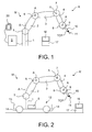
- the Fig. 1 shows a robot R, which has a robot arm M and a control device S.
- the robot arm M essentially represents the movable part of the robot R and comprises a plurality of successive links 1-4, which are connected to each other by means of joints 5-8.
- the robot arm M has a fastening device 9, for example in the form of a flange, on which, for example, an end effector can be fastened.
- the robot arm M further comprises drives, not shown, connected to the control device S, by means of which the links 1-4 can be moved relative to one another with respect to axes A.
- the drives are, for example, electric drives and are controlled by the control device S in the automatic mode of the robot R, so that the fastening device 9 or a so-called tool center point TCP of the robot R automatically performs a predetermined movement.
- the control device S may in particular be designed such that it controls the drives in automatic mode.
- the robot arm M has seven axes A, i. the robot R is a so-called 7-axis robot.
- the robot R is a so-called 7-axis robot.
- the user program of the robot R is created by a person, not shown, manually moving the robot arm M so that the fixture 9 or the tool center point TCP assumes a predetermined pose. Subsequently, the axis position of the robot arm M corresponding to this pose is stored in the control device S. This is repeated if necessary for several points 11, whereby the robot R or its control device S in automatic mode can control the robot arm M in such a way that the fastening device 9 or the tool center point TCP executes the desired movement.
- a teaching tool 10 can be fastened to the fastening device 9 in order to allow the person e.g. to give an indication of the Tool Center Point TCP.
- the robot R or its robot arm M can be moved, for example, by manual guidance, ie the person can move the robot arm M eg by pulling or pressing on the structure of the robot arm M or by pulling on the teaching tool 10 move manually, so that the fastening device 9 is aligned according to the desired pose of the tool center point TCP.
- the robot R can be connected by means of a device which can be connected to the control device 3 and in which Fig. 3 manual control unit 20 shown in detail moved manually and optionally programmed.
- Handheld terminal 20 includes, for example, electronics that includes a microprocessor to communicate with the controller S can.
- the handheld terminal 20 comprises a display designed as a touch screen 21, an emergency stop button 22 and a changeover switch 23 designed as a lock.
- the robot can be activated by means of the handheld terminal 20 R can be switched from its automatic to manual mode for manual movement.
- the emergency stop button 22 is activated, the robot R automatically stops its movement.
- the handheld terminal 20 can be set menu-guided.
- the hand-held operating device 20 comprises two different input devices or displacement means 24, 25 which can be manually actuated independently of one another.
- One of the two displacement means 24 is e.g. as a 6D mouse and the other traversing means 15 is executed, for example, as a plurality of rocker buttons.
- the 6D mouse also referred to as a space mouse, when activated allows movement of the robot arm R in six degrees of freedom.
- the rocker buttons are e.g. assigned to the individual axes A of the robot arm M, so that by means of the rocker buttons also the robot arm M can be moved manually.
- the robot arm M for example, by means of the manual control unit 20 and / or by Manual guidance is moved manually such that the Tool Center Point TCP assumes its desired pose at point 11. Since the robot R is a 7-axis robot, there are theoretically infinitely many axis positions of the robot arm M for this pose.
- a computer program runs on the control device S and / or on a computer 17, which evaluates the current axis position of the robot arm M for the desired pose in accordance with at least one predefined or predefinable criterion. Due to the evaluation based on the at least one criterion, the person may e.g. on the touch screen 22 of the handheld terminal 20 and / or on another display device 16 information about the weighted axis position of the robot arm M are displayed. The information about the rating may e.g. as a numerical value of e.g.
- the evaluation on the basis of the criterion can be carried out in particular by means of an optimization method in which, in particular, the at least one criterion is the parameter of the optimization method.
- the current axle position is evaluated on the basis of the distances of the axles A, then the more the members 1-4 are removed from their end stops, the better the current axle position is evaluated. Accordingly, the beam 25 is longer. Are e.g. in the desired pose, the maximum distances assigned to the current axle position, then the bar 25 has its maximum length. If the score is indicated by numbers, e.g. "1" maximum distance to the end stops.
- the manipulability of the robot arm M can e.g. be calculated by means of the so-called Jaccobi matrix, which is generally known to the person skilled in the art, and which is assigned to the axis position of the robot arm M.
- Jaccobi matrix which is generally known to the person skilled in the art, and which is assigned to the axis position of the robot arm M.
- the torques may e.g. be determined by Achsmomentensensoren the robot arm M.
- the rating is better, the lower the torques acting on the robot arm M or its members 1-4.
- the energy efficiency is e.g. assigned to the drives, which consume different amounts of energy according to the Achswolf.
- the person programming the robot R is allowed to set different axle positions for a desired pose of the Tool Center Point TCP by trial and error To get an evaluation of the different axis positions, in order to be able to decide which of the axis positions should be programmed for the desired pose.
- the Fig. 2 shows another robot R '. Unless otherwise stated, then are components of in the Fig. 2 shown robot R ', with components of in the Fig. 1 shown robot R are substantially identical in construction and function, provided with the same reference numerals.
- the robot arm M On the vehicle body 13, the robot arm M is fixed and on or in the vehicle body 13, the control device S is arranged.
- the wheels 14 are, for example, omnidirectional wheels and are driven, for example, by drives, not shown in detail, in particular electric drives, so that the robot arm M can be moved by means of the mobile platform 12.
- the drives of the wheels 14 are in particular connected to the control device S, so that the mobile robot R 'can be moved automatically by means of the mobile platform 12.
- the robot R ' may also be a 7-axis robot, but may also have less than 7 axes A.
- the mobile robot R ' can be provided, for example, to grasp an object by means of a gripper 15 attached to the fastening device 9.
- the person programming the robot R ' manually advances this eg controlled by the manual operating device 20 to a receiving station to a position, and then the robot arm M of the robot R ', for example, by manually guiding and / or by manually moving by means of the manual operating device 20 in such a way that the fastening device 9 or the tool center point TCP assumes a desired pose at point 11.
- the control device S drives the drives of the robot arm M suitable.
- the current evaluation of the axle position is calculated and displayed.
- the person is allowed to determine a better, if not optimal, position or location for the mobile platform R 'of the mobile robot R' for programming.
- the rating can be for single points 11 or for several points 11. It is also possible, in addition to this purely point-related evaluation, to also create a rating with regard to entire lanes or partial lanes. By changing the axle position at a point 11, the axis positions of the entire movement change. This can also be evaluated and displayed. Thus, further criteria for evaluation, such as e.g. Energy optimality, cycle time (maximum speed on the train), speed accuracy, track fidelity and / or other variables that depend on the respective axis positions and gradients.
- predefined criteria can be made available to the person programming the robot R, R ', which can select or deselect them by configuration. If the score is normalized, i. e.g. between "0" and "1", then it may be provided that a plurality of criteria should be used for the assessment, to separately display the ratings associated with each optionally selected criteria, or to display the score as a combined value. With the help of appropriate weighting factors, the individual criteria can be weighted differently.
- the person programming the robot R, R ' can implement his own criteria or evaluation functions.
- it can be provided with a framework in which it can formulate any evaluation function with the aid of a suitable description language and integrate it into the system.
Abstract
Description
Die Erfindung betrifft Verfahren zum Programmieren eines Roboters.The invention relates to methods for programming a robot.
Roboter im Allgemeinen sind Handhabungsmaschinen, die zur selbsttätigen Handhabung von Objekten mit zweckdienlichen Werkzeugen ausgerüstet und in mehreren Bewegungsachsen insbesondere hinsichtlich Orientierung, Position und Arbeitsablauf programmierbar sind. Roboter weisen üblicherweise einen Roboterarm mit mehreren Gliedern und programmierbare Steuerungen (Steuervorrichtungen) auf, die während des Betriebs die Bewegungsabläufe des Roboterarms steuern bzw. regeln. Die Antriebe sind z.B. elektrische Antriebe.Robots in general are handling machines that are equipped for the automatic handling of objects with appropriate tools and are programmable in several axes of motion, in particular with regard to orientation, position and workflow. Robots typically include a multi-limb robotic arm and programmable controllers (control devices) that control the movements of the robotic arm during operation. The drives are e.g. electric motors.
Die Aufgabe der Erfindung ist es, ein verbessertes Verfahren zum Programmieren eines Roboters anzugeben.The object of the invention is to provide an improved method for programming a robot.
Die Aufgabe der Erfindung wird gelöst durch ein Verfahren zum Programmieren eines Roboters, der einen mehrere, nacheinander folgende Glieder, eine Befestigungsvorrichtung zum Befestigen eines Endeffektors und Antriebe zum Bewegen der Glieder aufweisenden Roboterarm und eine mit den Antrieben verbundene Steuervorrichtung aufweist, aufweisend folgende Verfahrensschritte:
- manuelles Bewegen des Roboterarms, sodass die Befestigungsvorrichtung und/oder ein dem Roboterarm zugeordneter Tool Center Point eine vorgegebene Pose einnimmt, wobei für diese Pose mehrere Stellungen von Achsen des Roboterarms, bezüglich derer die Glieder mittels der Antriebe bewegbar sind, möglich sind,
- automatisches Bewerten der aktuellen Stellung der Achsen des Roboterarms für die aktuelle Pose aufgrund wenigstens eines vorgegebenen und/oder vorgebbaren Kriteriums insbesondere mittels der Steuervorrichtung und/oder einer Rechenvorrichtung, und
- Anzeigen des Ergebnisses des Bewertens der aktuellen Stellung der Achsen mittels einer Anzeigevorrichtung.
- manually moving the robot arm such that the attachment device and / or a tool center point associated with the robot arm assumes a predetermined pose, wherein for this pose several positions of axes of the robot arm with respect to which the elements are movable by means of the drives are possible;
- automatically assessing the current position of the robot arm's axes for the current pose due to at least a predetermined and / or predefinable criterion, in particular by means of the control device and / or a computing device, and
- Displaying the result of evaluating the current position of the axles by means of a display device.
In manchen Roboteranwendungen gibt es Aufgaben, die aufgrund der eingesetzten Kinematik, d.h. aufgrund des verwendeten Roboters bzw. dessen Roboterarms und einer dadurch gegebenenfalls bestehenden Redundanz auf mehrere Arten, d.h. Roboterposen gelöst werden können. Redundanzen können u.a. in Aufgabenredundanz und Kinematikredundanz eingeteilt werden.In some robotic applications there are tasks which, due to the kinematics used, i. due to the robot or its robot arm used and any redundancy that may exist in several ways, i. Robot poses can be solved. Redundancies can i.a. be divided into task redundancy and kinematics redundancy.
Unter Aufgabenredundanz wird verstanden, dass z.B. die kartesische Aufgabe für eine bestimmte Pose der Befestigungsvorrichtung und/oder des Tool Center Points mit weniger als sechs Freiheitsgraden gegeben ist und ein Roboterarm mit wenigstens 6 Achsen, insbesondere mit genau 6 Achsen verwendet wird. Ein Beispiel hierfür sind Aufgaben mit rotationssymmetrischen Werkzeugen bzw. Endeffektoren, z.B. für ein Kleben, Schweißen, Bohren, etc., bei denen die Orientierung um die Werkzeugachse (z-Achse) nicht durch den Prozess vorgegeben ist. Aber auch Aufgaben, bei denen der Prozess Toleranzen bezüglich der Werkzeugorientierung bzw. der Orientierung des Endeffektors zulässt (z.B. unterschiedliche Anstellwinkel beim Schweißen), zählen zur Aufgabenredundanz. Um eine Eindeutigkeit für die zu programmierende Pose zu erzielen, sollte die den Roboter programmierende Person diese variable Größe explizit vorgeben, so dass gegebenenfalls eine eindeutige 6 dimensionale kartesische Stellung des Roboterarms entsteht, die dann wieder "eindeutig" auf eine Pose zurückgeführt werden kann.Under task redundancy is understood that, for example, the Cartesian task for a particular pose of the fastening device and / or the Tool Center Points is given with less than six degrees of freedom and a robot arm with at least 6 axes, in particular with exactly 6 axes is used. An example of this are tasks with rotationally symmetrical tools or end effectors, eg for gluing, welding, drilling, etc., in which the orientation about the tool axis (z-axis) is not predetermined by the process. But tasks in which the process allows tolerances with respect to the tool orientation or the orientation of the end effector (eg different angles of incidence during welding) are part of the task redundancy. In order to achieve a uniqueness for the pose to be programmed, the person programming the robot should explicitly specify this variable size so that, if necessary, a unique 6-dimensional Cartesian position of the robot arm is created, which can then be traced back "clearly" to a pose.
Unter Kinematikredundanz wird die Nutzung einer Kinematik bzw. eines Roboterarms mit mehr als 6 Freiheitsgraden verstanden, sodass eine kartesisch vorgegebene Aufgabe mit mehreren Achsstellungen gelöst werden kann. Beispiele von solchen Roboterarmen sind 7-Achsroboter insbesondere mit einem Redundanzparameter "Ellbogenwinkel", 6-Achsroboter auf einer Lineareinheit mit Redundanzparameter "Fußpunktposition auf Lineareinheit", 6-Achs-Laseroboter mit optischer Zoomeinheit mit Redundanzparameter "Fokuslänge", Roboter mit einer mobilen Plattform, auf der der Roboterarm befestigt ist, mit den Redundanzparamtern xBase, y Base, zBase.Kinematics redundancy is the use of a kinematics or a robot arm with more than 6 degrees of freedom, so that a Cartesian given task can be solved with multiple axis positions. Examples of such robot arms are 7-axis robots, in particular with a "elbow angle" redundancy parameter, 6-axis robot on a linear unit with redundancy parameter "base point on linear unit", 6-axis laser robot with optical zoom unit with redundancy parameter "focus length", robot with a mobile platform, on which the robot arm is mounted, with the redundancy parameters xBase, y Base, zBase.
Allgemein ist es also möglich, dass für die zu programmierende Pose mehrere Achsstellungen des Roboterarms möglich sind. Erfindungsgemäß wird nun, nachdem die den Roboter programmierende Person den Roboterarm derart manuell bewegt hat, sodass dieser die Pose einnimmt, die aktuelle Stellung der Achsen (Achsstellung) bewertet und die Bewertung auf einer Anzeigevorrichtung dargestellt. Somit erhält die Person einen Anhaltspunkt darüber, ob die aktuelle Stellung der Achsen "günstig" ist oder ob sie gegebenenfalls die Stellung des Roboterarms bei beibehaltener Pose ändern soll, um für diese Pose eine bessere oder der aktuellen Aufgabenstellung günstigere Stellung der Achsen zu erhalten. Anschließend kann die gefundene bzw. die gewollte Achsstellung gespeichert werden, um die Programmierung des Roboters zu erhalten, d.h. um das Anwenderprogramm zu erhalten, aufgrund dessen der Roboterarm im Automatikbetrieb automatisch von der Steuervorrichtung gesteuert wird.In general, it is therefore possible that multiple axis positions of the robot arm are possible for the pose to be programmed. According to the invention, now that the person programming the robot has manually moved the robot arm so that it assumes the pose, the current position of the axes (axis position) is evaluated and the evaluation is displayed on a display device. Thus, the person receives an indication as to whether the current position of the axes is "favorable" or whether they should change the position of the robot arm if the pose is maintained, in order to obtain for this pose a better or the current task more favorable position of the axes. Subsequently, the found or desired axle position can be stored in order to obtain the programming of the robot, i. in order to obtain the user program, by virtue of which the robot arm is automatically controlled by the control device in automatic mode.
Gemäß dem erfindungsgemäßen Verfahren wird der Roboterarm manuell bewegt. Dies kann gemäß einer Variante des erfindungsgemäßen Verfahrens durch ein manuelles Führen des Roboterarms erreicht werden, d.h. dass die den Roboter programmierende Person den Roboterarm z.B. durch Ziehen und/oder Drücken an der Struktur des Roboterarms manuell bewegt. Auch ist es möglich, dass für das manuelle Führen eine entsprechende Vorrichtung z.B. in Form eines Griffs an der Befestigungsvorrichtung befestigt ist, mittels derer der Roboterarm manuell geführt werden kann.According to the inventive method, the robot arm is moved manually. This can be achieved according to a variant of the method according to the invention by manually guiding the robot arm, ie that the person programming the robot robot arm, for example by pulling and / or Pushing on the structure of the robot arm moves manually. It is also possible for a corresponding device, for example in the form of a handle, to be attached to the fastening device by means of which the robot arm can be manually guided.
Das manuelle Bewegen kann nach einer weiteren Variante des erfindungsgemäßen Verfahrens mittels eines mit der Steuervorrichtung verbundenen Handbediengerätes realisiert werden. Handbediengeräte als solche sind dem Fachmann im Prinzip bekannt.The manual movement can be realized according to a further variant of the method according to the invention by means of a handheld terminal connected to the control device. Handheld terminals as such are known in the art in principle.
Anstelle des manuellen Bewegens des Roboterarms ist es nach einer Ausführungsform des erfindungsgemäßen Verfahrens auch möglich, die Stellung der Achsen des Roboterarms mittels einer Rechenvorrichtung derart zu simulieren, sodass die Befestigungsvorrichtung und/oder der Tool Center Point eine simulierte vorgegebene Pose einnimmt. Dann wird gemäß dieser Variante die simulierte aktuelle Stellung der Achsen des Roboterarms für die simulierte aktuelle Pose aufgrund des wenigstens einen Kriteriums bewertet und die Bewertung der simulierten aktuellen Stellung der Achsen mittels einer Anzeigevorrichtung angezeigt. Daher wird es der den Roboter programmierenden Person ermöglich, eine geeignete Achsstellung für die gewünschte Pose, unterstützt durch die angezeigte Bewertung der simulierten Achsstellung, zu finden. Die gewünschte Achsstellung kann dann gespeichert werden, um das Anwenderprogramm, aufgrund dessen der Roboter automatisch sich bewegen soll, zu erhalten.Instead of manually moving the robot arm, according to one embodiment of the method according to the invention, it is also possible to simulate the position of the axes of the robot arm by means of a computing device such that the fastening device and / or the tool center point assumes a simulated predetermined pose. Then, according to this variant, the simulated current position of the axes of the robot arm for the simulated current pose is evaluated on the basis of the at least one criterion, and the evaluation of the simulated current position of the axes is displayed by means of a display device. Therefore, the person programming the robot will be able to find an appropriate axle position for the desired pose, supported by the simulated axle position evaluation displayed. The desired axis position can then be saved in order to obtain the user program, by virtue of which the robot is to move automatically.
Somit wird gemäß dieser Variante im Wesentlichen folgendes Verfahren bereit gestellt: Verfahren zum Programmieren eines Roboters, der einen mehrere, nacheinander folgende Glieder, eine Befestigungsvorrichtung zum Befestigen eines Endeffektors und Antriebe zum Bewegen der Glieder aufweisenden Roboterarm und eine mit den Antrieben verbundene Steuervorrichtung aufweist, aufweisend folgende Verfahrensschritte:
- mittels einer Rechenvorrichtung, Simulieren einer Stellung der Achsen des Roboterarms, sodass die Befestigungsvorrichtung und/oder ein dem Roboterarm zugeordneter Tool Center Point eine simulierte vorgegebene Pose einnimmt, wobei für diese Pose mehrere Stellungen der Achsen des Roboterarms möglich sind,
- automatisches Bewerten der simulierten aktuellen Stellung der Achsen des Roboterarms für die simulierte aktuelle Pose aufgrund wenigstens eines vorgegebenen und/oder vorgebbaren Kriteriums insbesondere mittels der Rechenvorrichtung, und
- Anzeigen der Bewertung der simulierten aktuellen Stellung der Achsen mittels einer Anzeigevorrichtung.
- by means of a computing device, simulating a position of the axes of the robot arm such that the attachment device and / or a tool center point associated with the robot arm assumes a simulated predetermined pose, whereby several positions of the axes of the robot arm are possible for this pose;
- automatically assessing the simulated current position of the axes of the robot arm for the simulated current pose due to at least one predetermined and / or predefinable criterion, in particular by means of the computing device, and
- Displaying the evaluation of the simulated current position of the axles by means of a display device.
Gemäß einer weiteren Variante des erfindungsgemäßen Verfahrens weist dieses die folgenden zusätzlichen Verfahrensschritte auf:
- manuelles Verändern der Stellung der Achsen bei gleichzeitigem Beibehalten der Pose der Befestigungsvorrichtung und/oder des Tool Center Points,
- automatisches Bewerten der veränderten Stellung der Achsen des Roboterarms für die aktuelle Pose aufgrund des wenigstens einen Kriteriums insbesondere mittels der Steuervorrichtung und/oder der Rechenvorrichtung, und
- Anzeigen des Ergebnisses des Bewertens der aktuellen veränderten Stellung der Achsen mittels der Anzeigevorrichtung.
- manually changing the position of the axes while maintaining the pose of the fixture and / or the Tool Center Points,
- automatically assessing the changed position of the axes of the robot arm for the current pose on the basis of the at least one criterion, in particular by means of the control device and / or the computing device, and
- Displaying the result of evaluating the current changed position of the axes by means of the display device.
Somit wird gemäß dieser Ausführungsform der den Roboter programmierenden Person während der Veränderung der Achsstellung eine aktualisierte Bewertung angezeigt, welche die Person bei der Entscheidung über die gewünschte Achsstellung, die dann gegebenenfalls programmiert wird, unterstützt. Wird die Stellung der Achsen simuliert, dann kann die Stellung der Achsen in der Simulation bei gleichbleibender Pose der Pose der Befestigungsvorrichtung und/oder des Tool Center Points verändert werden, die simulierte veränderte Stellung der Achsen des Roboterarms für die aktuelle Pose aufgrund des wenigstens einen Kriteriums bewertet werden, und das Ergebnis des Bewertens der aktuellen simulierten veränderten Stellung der Achsen mittels der Anzeigevorrichtung angezeigt werden.Thus, according to this embodiment, the person programming the robot displays an updated score during the change of the axle position, which assists the person in deciding the desired axle position, which is then optionally programmed. If the position of the axes is simulated, then the position of the axes in the simulation can be changed while maintaining the pose of the fixture and / or the tool center point, the simulated changed position of the axes of the robot arm for the current pose due to the at least one criterion are evaluated, and the result of evaluating the current simulated changed position of the axes are displayed by means of the display device.
Das wenigstens eine Kriterium kann wenigstens eines der Folgenden sein:
- Abstände der Achsen von den jeweiligen Endanschlägen der entsprechenden Glieder des Roboterarms,
- Manipulierbarkeit des Roboterarms,
- wirkende Drehmomente auf die einzelnen Glieder des Roboterarms,
- maximale Kraft, die der Roboterarm in der aktuellen Stellung der Achsen aufbringen kann, und/oder
- Energieeffizienz insbesondere der Antriebe in der aktuellen Stellung der Achsen.
- Distances of the axes from the respective end stops of the corresponding members of the robot arm,
- Manipulability of the robot arm,
- acting torques on the individual members of the robot arm,
- maximum force that the robot arm can apply in the current position of the axles, and / or
- Energy efficiency, especially of the drives in the current position of the axes.
Wird z.B. die aktuelle Achsstellung aufgrund der Abstände der Achsen bewertet, dann wird beispielsweise die aktuelle Achsstellung umso besser bewertet, je weiter die Glieder von ihren Endanschlägen entfernt sind.If, for example, the current axis position is evaluated on the basis of the distances of the axes, then, for example, the current axis position Axis position the better the further the links are from their end stops.
Die Manipulierbarkeit des Roboterarms kann z.B. mittels der sogenannten, dem Fachmann allgemein bekannten Jaccobi-Matrix berechnet werden, welche der Achsstellung des Roboterarms zugeordnet ist. Je größer die Manipulierbarkeit des Roboterarms ist, desto besser ist die Bewertung der aktuellen Achsstellung.The manipulability of the robotic arm may e.g. be calculated by means of the so-called Jaccobi matrix, which is generally known to the person skilled in the art, and which is assigned to the axis position of the robot arm. The greater the manipulability of the robot arm, the better the evaluation of the current axis position.
Die Drehmomente können z.B. mittels Achsmomentensensoren des Roboterarms bestimmt oder auch simuliert werden. Die Bewertung ist besser, je geringer die auf den Roboterarm bzw. dessen Glieder wirkenden Drehmomente sind.The torques may e.g. be determined or simulated by Achsmomentensensoren the robot arm. The rating is better, the lower the torques acting on the robot arm or its members.
Die Energieeffizienz ist z.B. den Antrieben zugeordnet, welche entsprechend der Achsstellung unterschiedlich viel Energie verbrauchen.The energy efficiency is e.g. assigned to the drives, which consume different amounts of energy according to the Achsstellung.
Die Bewertung kann z.B. als ein Zahlenwert oder auch als ein normierter Zahlenwert von "0" bis "1" angezeigt werden. Nach einer Variante des erfindungsgemäßen Verfahrens wird jedoch das Anzeigen des Bewertens der aktuellen Stellung der Achsen mittels eines grafischen Balkens angezeigt. Die Länge des Balkens ist dann beispielsweise ein Maß dafür, wie günstig die aktuelle Achsstellung ist.The rating may e.g. displayed as a numerical value or as a normalized numerical value from "0" to "1". According to a variant of the method according to the invention, however, displaying the evaluation of the current position of the axes by means of a graphic bar is displayed. The length of the bar is then, for example, a measure of how favorable the current axle position is.
Nach einer weiteren Ausführungsform des erfindungsgemäßen Verfahrens weist dieses ein automatisches Bewerten der aktuellen Stellung bzw. der aktuell simulierten Stellung der Achsen des Roboterarms für die aktuelle Pose aufgrund mehrerer vorgegebener und/oder vorgebbarer Kriterien insbesondere mittels der Steuervorrichtung und/oder der Rechenvorrichtung. Dann ist es z.B. möglich, die individuellen Bewertungen der aktuellen Stellung bzw. der aktuell simulierten Stellung der Achsen mittels der Anzeigevorrichtung für jedes der Kriterien anzuzeigen. Es ist aber alternativ oder zusätzlich möglich die Bewertung für die Gesamtheit aller Kriterien anzuzeigen. Hierbei können die einzelnen Kriterien auch unterschiedlich stark gewichtet werden.According to a further embodiment of the method according to the invention, this has an automatic evaluation of the current position or the currently simulated position of the axes of the robot arm for the current pose on the basis of a plurality of predetermined and / or predefinable criteria, in particular by means of the control device and / or the computing device. Then it is possible, for example, the individual assessments of the current position or the currently simulated To indicate the position of the axes by means of the display device for each of the criteria. However, it is alternatively or additionally possible to display the rating for the totality of all criteria. Here, the individual criteria can also be weighted differently.
Weist der Roboter eine mobile Plattform auf, an der der Roboterarm befestigt ist, dann kann gemäß einer Variante des erfindungsgemäßen Verfahrens diese ein Bewegen der mobilen Plattform an eine Position aufweisen, bevor der Roboterarm derart manuell bewegt wird, sodass die Befestigungsvorrichtung und/oder der Tool Center Point die vorgegebene Pose einnimmt. Die mobile Plattform weist z.B. einen Fahrzeugkörper auf, an dem der Roboterarm befestigt ist, und mehrere, an dem Fahrzeugkörper angeordnete Räder. Am oder im Fahrzeugkörper kann die Steuervorrichtung angeordnet sein. Die Räder oder zumindest eines der Räder können bzw. kann von Antrieben bzw. einem Antrieb angetrieben werden, die bzw. der von der Steuervorrichtung angesteuert werden kann. Dann ist es möglich, dass sich der als mobile Roboter ausgebildete Roboter im Automatikbetrieb automatisch gesteuert von der Steuervorrichtung bewegt. Der wenigstens einen Antrieb kann insbesondere als ein elektrischer Antrieb ausgeführt sein. Auch kann die Bewegung der mobilen Plattform simuliert werden.If the robot has a mobile platform to which the robot arm is fastened, then, according to a variant of the method according to the invention, it can move the mobile platform to a position before the robot arm is moved manually such that the fastening device and / or the tool Center Point takes the predetermined pose. The mobile platform has e.g. a vehicle body to which the robot arm is attached, and a plurality of wheels disposed on the vehicle body. On or in the vehicle body, the control device may be arranged. The wheels or at least one of the wheels can or can be driven by drives or a drive which can be controlled by the control device. Then, it is possible for the robot designed as a mobile robot to move automatically controlled by the control device in automatic mode. The at least one drive can be designed in particular as an electric drive. Also, the movement of the mobile platform can be simulated.
Wird ein als mobiler Roboter ausgebildeter Roboter verwendet, dann kann gemäß einer Ausführungsform des erfindungsgemäßen Verfahrens dieses folgende Verfahrensschritte aufweisen:
- Verändern der Position und/oder Lage der mobilen Plattform bei gleichzeitigem Beibehalten der Pose der Befestigungsvorrichtung und/oder des Tool Center Points,
- automatisches Bewerten der veränderten Stellung der Achsen des Roboterarms für die aktuelle Pose aufgrund des wenigstens einen Kriteriums insbesondere mittels der Steuervorrichtung und/oder der Rechenvorrichtung, und
- Anzeigen der Bewertung der aktuellen Stellung der Achsen mittels der Anzeigevorrichtung.
- Changing the position and / or position of the mobile platform while maintaining the pose of the attachment device and / or the tool center point,
- automatically assessing the changed position of the axes of the robot arm for the current pose on the basis of the at least one criterion, in particular by means of the control device and / or the computing device, and
- Displaying the evaluation of the current position of the axes by means of the display device.
Dies kann auch mittels des Simulierens durchgeführt werden. Somit ist es möglich, nachdem die gewollte Pose eingestellt ist, nicht nur die Stellungen der Achsen zu verändern, sei es durch manuelles Bewegen oder in der Simulation, sondern auch die Position bzw. Lage der mobilen Plattform ohne dass sich die Pose der Befestigungsvorrichtung bzw. des Tool Center Points ändert. Damit die Pose beim Verändern der Position oder Lage der mobilen Plattform unverändert bleibt, kann die Steuervorrichtung derart eingerichtet sein, dass sie automatisch den Roboterarm entsprechend bewegt. Hat die den Roboter programmierende Person eine Position oder Lage der mobilen Plattform für die gewünschte Pose gefunden, die sie als günstig erachtet, dann können die entsprechenden Stellungen der Achsen und die entsprechende Position bzw. Lage der mobilen Plattform für das Anwenderprogramm gespeichert werden.This can also be done by means of simulating. Thus, it is possible, after the desired pose is set, not only to change the positions of the axes, either by manually moving or in the simulation, but also the position or position of the mobile platform without the pose of the fastening device or of the Tool Center Point changes. In order for the pose to remain unchanged as the position or attitude of the mobile platform changes, the controller may be configured to automatically move the robot arm accordingly. If the person programming the robot has found a position or location of the mobile platform for the desired pose that he considers favorable, then the corresponding positions of the axes and the corresponding position of the mobile platform for the application program can be stored.
Je nach Ausführungsform des erfindungsgemäßen Verfahrens wird demnach die eingestellte Pose aufgrund eines oder unterschiedlicher Kriterien bewertet. Beispiele für eine solche Bewertung sind z.B. Abstand der Achsen von den jeweiligen Achsendanschlägen und "Abstand" von Singularitäten der Jaccobi-Matrix, entsprechend der Manipulierbarkeit des Roboterarms.Depending on the embodiment of the method according to the invention, the adjusted pose is therefore evaluated on the basis of one or different criteria. Examples of such a rating are e.g. Distance of the axes from the respective axial end stops and "distance" of singularities of the Jaccobi matrix, corresponding to the manipulability of the robot arm.
In einem entsprechenden Bewertungsmodul, das z.B. in der Steuervorrichtung oder der anderen Rechenvorrichtung hinterlegt ist, kann nun aus der aktuellen Achsstellung des realen oder simulierten Roboters die Bewertung gemäß des wenigstens einen vorgegebenen oder vorgebbaren Kriteriums erfolgen. Ausgabe dieses Bewertungsmoduls ist insbesondere ein Maß für die Güte der aktuellen Achsstellung. Diese Bewertungsgüte kann ein absolutes Maß sein (z.B. 6 Werte für den Abstand der Achsen zum Endanschlag in Winkelgrad bzw. Summe, Mittelwert, Minimalwert der Winkel) oder vorzugsweise ein genormter Wert zwischen "0" und "1", der die Güte quantitativ angibt (Beispielsweise "0" = sehr schlecht bis "1" = sehr gut).In a corresponding evaluation module, for example, deposited in the control device or the other computing device is, can now be made from the current axis position of the real or simulated robot evaluation in accordance with the at least one predetermined or predeterminable criterion. Output of this evaluation module is in particular a measure of the quality of the current axle position. This evaluation quality can be an absolute measure (
Diese Bewertung bzw. Bewertungsgüte wird der den Roboter programmierenden Person angezeigt, beispielsweise als Zahlenwert oder vorzugsweise graphisch z.B. als Balken oder auf andere intuitive Art und Weise. Die Anzeige kann sowohl in einer Simulationsumgebung als auch auf dem Programmierhandgerät bzw. Handbediengerät erfolgen. Auch ein Einblenden mittels Augmented Reality direkt in die Szene ist denkbar.This rating is displayed to the person programming the robot, for example, as a numerical value or, preferably, graphically e.g. as a bar or in another intuitive way. The display can be carried out both in a simulation environment and on the programming pendant or handheld terminal. Even fading in with augmented reality directly into the scene is conceivable.
Der den Roboter programmierenden Person wird es somit ermöglicht, den bzw. die freien Redundanzparameter verändern zu können, sodass beispielsweise die kartesischen Prozessvorgaben weiterhin erfüllt werden. Beispielsweise kann der Roboterarm um die Z-Achse gedreht werden, wenn beispielsweise symmetrische Werkzeuge verwendet werden, oder der Ellbogenkreis eines 7-Achs Roboters kann verändert werden. Währenddessen kann vorzugsweise der Person die jeweils aktuelle Bewertungsgüte dargestellt werden, sodass sie direkt eine Rückmeldung bekommt und so eine verbesserte, wenn nicht gar optimale Stellung bezüglich der angezeigten Bewertungskriterien auswählen kann.The person programming the robot is thus enabled to be able to change the free redundancy parameter (s) so that, for example, the Cartesian process instructions continue to be met. For example, the robot arm may be rotated about the Z-axis when, for example, symmetrical tools are used, or the elbow of a 7-axis robot may be changed. In the meantime, it is preferable for the person to be presented with the respective current evaluation quality, so that he directly receives feedback and can thus select an improved, if not optimal, position with regard to the displayed evaluation criteria.
Ein weiteres Beispiel für die Verwendung des erfindungsgemäßen Verfahrens ist ein mobiler Manipulator bzw. ein mobiler Roboter, der z.B. ein Objekt greifen soll. Hier kann die Person die gegebenenfalls vorhandene mobile Plattform, auf der der Roboterarm gegebenenfalls befestigt ist, beispielsweise an die Aufnahmestation fahren. Hierbei wählt sie beispielsweise erst mal eine ihres Erachtens geeigneten Position für die mobile Plattform aus. Anschließend kann sie den Roboterarm so zum Zielort (Greifposition) als solchen bewegen. Anschließend bekommt sie gegebenenfalls direkt eine visuelle Rückmeldung, welche die aktuelle Pose des Roboterarms bewertet. Nun kann sie die Position der mobilen Plattform verändern, während die Position bzw. Pose des Greifers unverändert bleibt. Aufgrund der Bewertungsgüte kann die Person somit eine bessere Position für die mobile Plattform finden und teachen.Another example of the use of the method according to the invention is a mobile manipulator or a mobile one Robot, for example, to grab an object. Here, the person can optionally drive the existing mobile platform on which the robot arm is attached, for example, to the receiving station. For example, she first selects a position for the mobile platform that she considers appropriate. Then it can move the robot arm to the destination (gripping position) as such. Subsequently, if necessary, it directly receives a visual feedback, which evaluates the current pose of the robot arm. Now she can change the position of the mobile platform, while the position or pose of the gripper remains unchanged. Due to the quality of evaluation, the person can thus find and teach a better position for the mobile platform.
Ein weiteres Bewertungskriterium kann sich aufgrund von gegebenenfalls verwendeten internen Achsmomentensensoren des Roboterarms ergeben. Je nach Achsstellung kann es sein, dass die berechneten kartesischen Kraft-/Momentenwerte unterschiedlich genau bzw. zuverlässig sind. Möchte die den Roboter programmierende Person beispielsweise Aufgaben programmieren, die die kartesische Kraft benötigen, so gibt es entsprechend günstige bzw. weniger günstige Achsstellungen. Entsprechende Bewertungsgüten für die "Kraftzuverlässigkeit" in x,y,z,a,b,c, Richtung kann der Person angezeigt werden.Another evaluation criterion may arise due to possibly used internal Achsmomentensensoren the robot arm. Depending on the axis position, it may be that the calculated Cartesian force / torque values are different or reliable. If, for example, the person programming the robot wants to program tasks which require the Cartesian force, then there are correspondingly favorable or less favorable axis positions. Corresponding evaluation qualities for the "force reliability" in x, y, z, a, b, c, direction can be displayed to the person.
Ein weiteres Beispiel für eine Bewertungsgüte wäre die Achsstellung, bei der die aufbringbare Kraft des Roboterarms in eine bestimmte Richtung maximal ist.Another example of an evaluation quality would be the axle position, in which the loadable force of the robot arm is maximum in a certain direction.
Neben diesen rein punktbezogenen Bewertungskriterien können die Kriterien auch bezüglich ganzer Bahnen erfolgen. Durch das Verändern der Achsstellung in einem Punkt ändern sich die Achsstellungen der gesamten Bewegung. Dies kann ebenfalls bewertet und angezeigt werden. Somit ergeben sich weitere Bewertungskriterien, wie z.B. Energieoptimalität, Taktzeit (max. Geschwindigkeit auf Bahn), Geschwindigkeitstreue, Bahntreue und/oder weitere Größen, die von den jeweiligen Achsstellungen und -verläufen abhängen.In addition to these purely point-related evaluation criteria, the criteria can also be applied to whole tracks. By changing the axis position in one point, the axis positions of the entire movement change. This can also be evaluated and displayed. Thus, there are more Evaluation criteria, such as energy optimality, cycle time (maximum speed on the train), speed accuracy, track fidelity and / or other variables that depend on the respective axis positions and gradients.
Ausführungsbeispiele der Erfindung sind exemplarisch in den beigefügten schematischen Zeichnungen dargestellt. Es zeigen:
- Fig. 1
- einen Roboter,
- Fig. 2
- einen mobilen Roboter und
- Fig. 3
- ein Handbediengerät zum manuellen Bewegen des Roboterarms des Roboters der
Fig. 1 .
- Fig. 1
- a robot,
- Fig. 2
- a mobile robot and
- Fig. 3
- a manual control unit for manually moving the robotic arm of the robot
Fig. 1 ,
Die
Der Roboterarm M weist ferner mit der Steuervorrichtung S verbundene, nicht näher dargestellte Antriebe auf, mittels derer die Glieder 1-4 bezüglich Achsen A relativ zueinander bewegt werden können. Die Antriebe sind z.B. elektrische Antriebe und werden im Automatikbetrieb des Roboters R von der Steuervorrichtung S angesteuert, sodass die Befestigungsvorrichtung 9 oder ein sogenannter Tool Center Point TCP des Roboters R automatisch eine vorbestimmte Bewegung durchführt. Zu diesem Zweck läuft auf der Steuervorrichtung S ein entsprechendes Anwenderprogramm. Die Steuervorrichtung S kann insbesondere derart ausgeführt sein, dass sie im Automatikbetrieb die Antriebe regelt.The robot arm M further comprises drives, not shown, connected to the control device S, by means of which the links 1-4 can be moved relative to one another with respect to axes A. The drives are, for example, electric drives and are controlled by the control device S in the automatic mode of the robot R, so that the
Im Falle des vorliegenden Ausführungsbeispiels weist der Roboterarm M sieben Achsen A auf, d.h. der Roboter R ist ein sogenannter 7-Achs-Roboter. Somit ergeben sich theoretisch für jede Pose, d.h. Position und Lage, der Befestigungsvorrichtung 9 bzw. des Tool Center Point TCP unendlich viele Achsstellungen des Roboterarms M.In the case of the present embodiment, the robot arm M has seven axes A, i. the robot R is a so-called 7-axis robot. Thus, theoretically, for every pose, i. Position and position, the
Im Falle des vorliegenden Ausführungsbeispiels wird das Anwenderprogramm des Roboters R erstellt, indem eine nicht näher dargestellte Person den Roboterarm M manuell derart bewegt, sodass die Befestigungsvorrichtung 9 bzw. der Tool Center Point TCP eine vorbestimmte Pose einnimmt. Anschließend wird die dieser Pose entsprechende Achsstellung des Roboterarms M in der Steuervorrichtung S gespeichert. Dies wird gegebenenfalls für mehrere Punkte 11 wiederholt, wodurch der Roboter R bzw. dessen Steuervorrichtung S im Automatikbetrieb den Roboterarm M derart ansteuern kann, sodass die Befestigungsvorrichtung 9 bzw. der Tool Center Point TCP die gewünschte Bewegung ausführt. Um der Person die Bedienung des Roboters R zu erleichtern, kann an der Befestigungsvorrichtung 9 ein Teachwerkzeug 10 befestigt werden, um der Person z.B. einen Hinweis auf den Tool Center Point TCP zu geben.In the case of the present embodiment, the user program of the robot R is created by a person, not shown, manually moving the robot arm M so that the
Um den Roboterarm R manuell zu bewegen, kann der Roboter R bzw. dessen Roboterarm M z.B. durch manuelles Führen bewegt werden, d.h. die Person kann den Roboterarm M z.B. durch Ziehen oder Drücken beispielsweise an der Struktur des Roboterarms M oder durch Ziehen am Teachwerkzeug 10 derart manuell bewegen, sodass die Befestigungsvorrichtung 9 entsprechend der gewünschten Pose des Tool Center Points TCP ausgerichtet ist.In order to move the robot arm R manually, the robot R or its robot arm M can be moved, for example, by manual guidance, ie the person can move the robot arm M eg by pulling or pressing on the structure of the robot arm M or by pulling on the
Alternativ oder zusätzlich kann es auch vorgesehen sein, dass der Roboter R mittels eines an die Steuervorrichtung 3 anschließbaren und in der
Im Falle des vorliegenden Ausführungsbeispiels umfasst das Handbediengerät 20 eine als Touch-Screen 21 ausgebildete Anzeige, eine Not-Aus Taste 22 und einen als Schloss ausgebildeten Umschalter 23. Mittels des Umschalters 23 bzw. eines nicht näher dargestellten Schlüssels kann mittels des Handbediengerätes 20 der Roboter R von seinem Automatik- in seinen Handbetrieb zum manuellen Bewegen umgeschaltet werden. Beim Aktivieren der Not-Aus Taste 22 stoppt der Roboter R seine Bewegung automatisch. Mittels des Touch-Screens 21 kann menügeführt das Handbediengerät 20 eingestellt werden.In the case of the present exemplary embodiment, the
Um den Roboterarm M manuell bewegen zu können, umfasst im Falle des vorliegenden Ausführungsbeispiels das Handbediengerät 20 zwei verschiedene und insbesondere voneinander unabhängig manuell betätigbare Eingabemittel bzw. Verfahrmittel 24, 25. Eine der beiden Verfahrmittel 24 ist z.B. als eine 6D-Maus und das andere Verfahrmittel 15 ist beispielsweise als mehrere Wipp-Tasten ausgeführt. Die 6D-Maus, die auch als Space-Maus bezeichnet wird, erlaubt, wenn aktiviert, eine Bewegung des Roboterarms R in sechs Freiheitsgraden. Die Wipp-Tasten sind z.B. den einzelnen Achsen A des Roboterarms M zugeordnet, sodass mittels der Wipp-Tasten ebenfalls der Roboterarm M manuell bewegt werden kann.In order to be able to move the robot arm M manually, in the case of the present exemplary embodiment the hand-held
Um nun das Anwenderprogramm zu erstellen, wird der Roboterarm M z.B. mittels des Handbediengerätes 20 und/oder durch manuelles Führen derart manuell bewegt, dass der Tool Center Point TCP im Punkt 11 seine gewünschte Pose einnimmt. Da es sich bei dem Roboter R um einen 7-Achs Roboter handelt, ergeben sich theoretisch unendlich viele Achsstellungen des Roboterarms M für diese Pose.In order to create the user program, the robot arm M, for example, by means of the
Im Falle des vorliegenden Ausführungsbeispiels läuft auf der Steuervorrichtung S und/oder auf einem Rechner 17 ein Rechnerprogramm, welches die aktuelle Achsstellung des Roboterarms M für die gewünschte Pose gemäß wenigstens einem vorgegebenen oder vorgebbaren Kriterium bewertet. Aufgrund der Bewertung aufgrund des wenigstens einen Kriteriums kann der Person z.B. auf dem Touch-Screen 22 des Handbediengerätes 20 und/oder auf einer anderen Anzeigevorrichtung 16 eine Information über die bewertete Achsstellung des Roboterarms M angezeigt werden. Die Information über die Bewertung kann z.B. als ein Zahlenwert von z.B. 1 bis 6 oder als normierter Zahlenwert zwischen 0 und 1 oder mittels eines Balkens 25 angezeigt werden, dessen Länge ein Maß für die Bewertung der aktuellen Achsstellung des Roboterarms M ist. Die Bewertung aufgrund des Kriteriums kann insbesondere mittels eines Optimierungsverfahrens durchgeführt geführt werden, bei welchem insbesondere das wenigstens eine Kriterium der Parameter des Optimierungsverfahrens ist.In the case of the present exemplary embodiment, a computer program runs on the control device S and / or on a
Im Falle des vorliegenden Ausführungsbeispiels kann die Bewertung der Achsstellung aufgrund wenigstens einer der folgenden Kriterien erfolgen:
- Abstände der Achsen A von den jeweiligen Endanschlägen der entsprechenden Glieder 1-4,
- Manipulierbarkeit des Roboterarms M,
- wirkende Drehmomente auf die einzelnen Glieder 1-4,
- Größe der Kraft, die der Roboterarm M aufbringen kann,
- Energieeffizienz.
- Distances of the axes A from the respective end stops of the respective members 1-4,
- Manipulability of the robot arm M,
- acting torques on the individual members 1-4,
- Size of force that the robot arm M can apply
- Energy efficiency.
Wird z.B. die aktuelle Achsstellung aufgrund der Abstände der Achsen A bewertet, dann wird die aktuelle Achsstellung umso besser bewertet, je weiter die Glieder 1-4 von ihren Endanschlägen entfernt sind. Dementsprechend ist der Balken 25 länger. Sind z.B. in der gewünschten Pose die der aktuellen Achsstellung zugeordneten Abstände maximal, dann weist der Balken 25 seine maximale Länge auf. Wird die Bewertung mittels Zahlen angezeigt, bedeutet z.B. "1" maximaler Abstand zu den Endanschlägen.If e.g. the current axle position is evaluated on the basis of the distances of the axles A, then the more the members 1-4 are removed from their end stops, the better the current axle position is evaluated. Accordingly, the
Die Manipulierbarkeit des Roboterarms M kann z.B. mittels der sogenannten, dem Fachmann allgemein bekannten Jaccobi-Matrix berechnet werden, welche der Achsstellung des Roboterarms M zugeordnet ist. Je größer die Manipulierbarkeit des Roboterarms M ist, desto besser ist die Bewertung der aktuellen Achsstellung.The manipulability of the robot arm M can e.g. be calculated by means of the so-called Jaccobi matrix, which is generally known to the person skilled in the art, and which is assigned to the axis position of the robot arm M. The greater the manipulability of the robot arm M, the better the evaluation of the current axis position.
Die Drehmomente können z.B. mittels Achsmomentensensoren des Roboterarms M bestimmt werden. Die Bewertung ist besser, je geringer die auf den Roboterarm M bzw. dessen Glieder 1-4 wirkenden Drehmomente sind.The torques may e.g. be determined by Achsmomentensensoren the robot arm M. The rating is better, the lower the torques acting on the robot arm M or its members 1-4.
Die Energieeffizienz ist z.B. den Antrieben zugeordnet, welche entsprechend der Achsstellung unterschiedlich viel Energie verbrauchen.The energy efficiency is e.g. assigned to the drives, which consume different amounts of energy according to the Achsstellung.
Aufgrund der Anzeige der Bewertung der aktuellen Achsstellung wird es der den Roboter R programmierenden Person erlaubt, für eine gewünschte Pose des Tool Center Points TCP unterschiedliche Achsstellung probehalber einzustellen und eine Bewertung der unterschiedlichen Achsstellungen zu erhalten, um selber entscheiden zu können, welche der Achsstellungen für die gewünschte Pose programmiert werden soll.On the basis of the display of the evaluation of the current axis position, the person programming the robot R is allowed to set different axle positions for a desired pose of the Tool Center Point TCP by trial and error To get an evaluation of the different axis positions, in order to be able to decide which of the axis positions should be programmed for the desired pose.
Die
Der Roboter R' unterscheidet sich im Wesentlichen vom Roboter R dadurch, dass der in der
Der Roboter R' kann ebenfalls ein 7-Achs Roboter sein, kann aber auch weniger als 7 Achsen A aufweisen. Der mobile Roboter R' kann z.B. vorgesehen sein, ein Objekt mittels eines an der Befestigungsvorrichtung 9 befestigten Greifers 15 zu greifen. Um dies zu programmieren, kann es im Falle des vorliegenden Ausführungsbeispiels vorgesehen sein, dass die den Roboter R' programmierende Person diesen z.B. gesteuert durch das Handbediengerätes 20 manuell an eine Aufnahmestation an eine Position heranfährt, und dann den Roboterarm M des Roboters R' z.B. durch manuelles Führen und/oder durch manuelles Bewegen mittels des Handbediengerätes 20 derart manuell bewegt, dass die Befestigungsvorrichtung 9 bzw. der Tool Center Point TCP im Punkt 11 eine gewünschte Pose einnimmt.The robot R 'may also be a 7-axis robot, but may also have less than 7 axes A. The mobile robot R 'can be provided, for example, to grasp an object by means of a
Anschließend wird ähnlich wie obenstehend beschrieben die Achsstellung zur eingestellten Pose bewertet und die Bewertung visuell beispielsweise am Handbediengerät 20 und/oder an der Anzeigevorrichtung 16 angezeigt. Anschließend kann die den Roboter R' programmierende Person die Position der mobilen Plattform 12 verändern, während die Lage des Greifers 15 oder des Teachwerkzeugs 10 bzw. die Pose des Tool Center Points TCP unverändert bleibt. Dies wird erreicht, indem die Steuervorrichtung S die Antriebe des Roboterarms M geeignet ansteuert. Entsprechend der geänderten Position oder Lage der mobilen Plattform 12 wird die aktuelle Bewertung der Achsstellung errechnet und angezeigt. Aufgrund der angezeigten Bewertung wird es somit der Person ermöglicht, eine bessere, wenn nicht gar optimale Position oder Lage für die mobilen Plattform 12 des mobilen Roboters R' für die Programmierung zu ermitteln.Subsequently, similar to the above described axis position is evaluated to set pose and the rating visually displayed, for example, on the
Es ist auch möglich, die Roboter R, R' mittels eines indirekten Verfahrens zu programmieren, indem die den Roboter R, R' programmierende Person für die gewünschte Pose unterschiedliche Achsstellungen des Roboterarms M und/oder verschieden Positionen oder Lagen der mobilen Plattform 12 simuliert, wobei die simulierten Achsstellungen entsprechend wie oben beschrieben bewertet und entsprechend der Bewertung ein Ergebnis des Bewertens auf einer Anzeigevorrichtung dargestellt werden. Die Simulation läuft z.B. auf dem Rechner 17.It is also possible to program the robots R, R 'by means of an indirect method in which the person programming the robot R, R' simulates different axis positions of the robot arm M and / or different positions or positions of the
Die Bewertung kann für einzelne Punkte 11 oder für mehrere Punkte 11 erfolgen. Es ist auch möglich, neben dieser rein punktbezogenen Bewertung auch eine Bewertung bezüglich ganzer Bahnen oder Teilbahnen zu erstellen. Durch das Verändern der Achsstellung in einem Punkt 11 ändern sich die Achsstellungen der gesamten Bewegung. Dies kann ebenfalls bewertet und angezeigt werden. Somit ergeben sich weitere Kriterien für die Bewertung, wie z.B. Energieoptimalität, Taktzeit (max. Geschwindigkeit auf Bahn), Geschwindigkeitstreue, Bahntreue und/oder weitere Größen, die von den jeweiligen Achsstellungen und -verläufen abhängen.The rating can be for
Es ist auch möglich, die Bewertung bzw. das oder die verwendeten Kriterien für die Bewertung der Achsstellung auszuwählen und zu kombinieren. Hierzu können beispielsweise der den Roboter R, R' programmierenden Person vordefinierte Kriterien zur Verfügung gestellt sein, die sie durch Konfiguration an- bzw. abwählen kann. Wird die Bewertung normiert angezeigt, d.h. z.B. zwischen "0" und "1", dann kann es vorgesehen sein, sollten mehrere Kriterien für die Bewertung verwendet werden, die den einzelnen gegebenenfalls ausgewählten Kriterien zugeordneten Bewertungen getrennt anzuzeigen oder die Bewertung als einen kombinierten Wert anzuzeigen. Mit Hilfe entsprechender Gewichtungsfaktoren können die Einzelkriterien unterschiedlich stark gewichtet werden.It is also possible to select and combine the rating or the one or more criteria used to evaluate the axle position. For this purpose, for example, predefined criteria can be made available to the person programming the robot R, R ', which can select or deselect them by configuration. If the score is normalized, i. e.g. between "0" and "1", then it may be provided that a plurality of criteria should be used for the assessment, to separately display the ratings associated with each optionally selected criteria, or to display the score as a combined value. With the help of appropriate weighting factors, the individual criteria can be weighted differently.
Es ist aber auch möglich, dass die den Roboter R, R' programmierende Person eigene Kriterien oder Bewertungsfunktionen implementieren kann. Hierzu kann ihr ein Rahmen zur Verfügung gestellt werden, indem sie eine beliebige Bewertungsfunktion mit Hilfe einer geeigneten Beschreibungssprache formulieren und in das System integrieren kann.However, it is also possible that the person programming the robot R, R 'can implement his own criteria or evaluation functions. For this purpose, it can be provided with a framework in which it can formulate any evaluation function with the aid of a suitable description language and integrate it into the system.
Claims (10)
Applications Claiming Priority (1)
| Application Number | Priority Date | Filing Date | Title |
|---|---|---|---|
| DE102011079117.5A DE102011079117B4 (en) | 2011-07-14 | 2011-07-14 | Method of programming a robot |
Publications (4)
| Publication Number | Publication Date |
|---|---|
| EP2546711A2 true EP2546711A2 (en) | 2013-01-16 |
| EP2546711A3 EP2546711A3 (en) | 2016-10-19 |
| EP2546711B1 EP2546711B1 (en) | 2018-05-16 |
| EP2546711B2 EP2546711B2 (en) | 2022-10-26 |
Family
ID=46798992
Family Applications (1)
| Application Number | Title | Priority Date | Filing Date |
|---|---|---|---|
| EP12175828.8A Active EP2546711B2 (en) | 2011-07-14 | 2012-07-11 | Method for programming a robot |
Country Status (2)
| Country | Link |
|---|---|
| EP (1) | EP2546711B2 (en) |
| DE (1) | DE102011079117B4 (en) |
Cited By (4)
| Publication number | Priority date | Publication date | Assignee | Title |
|---|---|---|---|---|
| WO2017025221A1 (en) * | 2015-08-12 | 2017-02-16 | Krones Aktiengesellschaft | Method for moving at least one handling unit designed for handling piece goods and device for handling piece goods |
| CN109643101A (en) * | 2016-04-16 | 2019-04-16 | J.G.魏瑟尔泽内有限责任两合公司 | The application of the touch-sensitive display of toolroom machine and the machine part for operated tool machine |
| WO2020064991A1 (en) * | 2018-09-28 | 2020-04-02 | Universite De Nantes | Robot arm system and method for emitting an information signal in the event of a critical state being detected in said robot arm system |
| US10676279B1 (en) | 2018-11-20 | 2020-06-09 | Advanced Intelligent Systems Inc. | Systems, methods, and storage units for article transport and storage |
Families Citing this family (14)
| Publication number | Priority date | Publication date | Assignee | Title |
|---|---|---|---|---|
| DE102013222456A1 (en) * | 2013-11-05 | 2015-05-07 | Kuka Laboratories Gmbh | Method for programming the motion sequences of a redundant industrial robot and associated industrial robots |
| US9403273B2 (en) * | 2014-05-23 | 2016-08-02 | GM Global Technology Operations LLC | Rapid robotic imitation learning of force-torque tasks |
| DE102015205176B3 (en) * | 2015-03-23 | 2016-05-12 | Kuka Roboter Gmbh | Robust intuitive operating method by touching a manipulator |
| CN104924313B (en) * | 2015-05-13 | 2017-03-01 | 北京工业大学 | There is teach-by-doing teaching mechanical arm system and the method for learning by imitation mechanism |
| JP6348141B2 (en) | 2016-04-28 | 2018-06-27 | ファナック株式会社 | Robot control device displaying operation program including additional axis status |
| EP3509800A4 (en) | 2016-09-06 | 2019-09-18 | Advanced Intelligent Systems Inc. | Mobile work station for transporting a plurality of articles |
| DE102017215114A1 (en) * | 2017-08-30 | 2019-02-28 | Deutsches Zentrum für Luft- und Raumfahrt e.V. | Manipulator system and method for controlling a robotic manipulator |
| WO2019157587A1 (en) | 2018-02-15 | 2019-08-22 | Advanced Intelligent Systems Inc. | Apparatus for supporting an article during transport |
| US10745219B2 (en) | 2018-09-28 | 2020-08-18 | Advanced Intelligent Systems Inc. | Manipulator apparatus, methods, and systems with at least one cable |
| US10751888B2 (en) | 2018-10-04 | 2020-08-25 | Advanced Intelligent Systems Inc. | Manipulator apparatus for operating on articles |
| US10966374B2 (en) | 2018-10-29 | 2021-04-06 | Advanced Intelligent Systems Inc. | Method and apparatus for performing pruning operations using an autonomous vehicle |
| US10645882B1 (en) | 2018-10-29 | 2020-05-12 | Advanced Intelligent Systems Inc. | Method and apparatus for performing pruning operations using an autonomous vehicle |
| JP7232704B2 (en) * | 2019-05-13 | 2023-03-03 | 株式会社トヨタプロダクションエンジニアリング | ROBOT PROGRAM EVALUATION DEVICE, ROBOT PROGRAM EVALUATION METHOD AND ROBOT PROGRAM EVALUATION PROGRAM |
| DE102019117219B4 (en) * | 2019-06-26 | 2021-07-08 | Franka Emika Gmbh | System for operating a graphical user interface |
Family Cites Families (7)
| Publication number | Priority date | Publication date | Assignee | Title |
|---|---|---|---|---|
| US5737500A (en) | 1992-03-11 | 1998-04-07 | California Institute Of Technology | Mobile dexterous siren degree of freedom robot arm with real-time control system |
| JP3207728B2 (en) | 1995-10-11 | 2001-09-10 | 三菱重工業株式会社 | Control method of redundant manipulator |
| DE102004021468A1 (en) | 2004-04-30 | 2005-11-24 | Kuka Roboter Gmbh | Method for controlling a machine, in particular an industrial robot |
| US7853356B2 (en) | 2006-04-14 | 2010-12-14 | Fanuc Robotics America, Inc. | Method for optimizing a robot program and a robot system |
| EP1974869A1 (en) | 2007-03-26 | 2008-10-01 | Honda Research Institute Europe GmbH | Apparatus and method for generating and controlling the motion of a robot |
| WO2011042049A1 (en) | 2009-10-06 | 2011-04-14 | Abb Technology Ab | A method for reducing the energy consumption of an industrial robot and an industrial robot system |
| DE102010039540C5 (en) | 2010-08-19 | 2020-01-02 | Kuka Deutschland Gmbh | Manual control device for moving a robot arm manually |
-
2011
- 2011-07-14 DE DE102011079117.5A patent/DE102011079117B4/en active Active
-
2012
- 2012-07-11 EP EP12175828.8A patent/EP2546711B2/en active Active
Non-Patent Citations (1)
| Title |
|---|
| None |
Cited By (6)
| Publication number | Priority date | Publication date | Assignee | Title |
|---|---|---|---|---|
| WO2017025221A1 (en) * | 2015-08-12 | 2017-02-16 | Krones Aktiengesellschaft | Method for moving at least one handling unit designed for handling piece goods and device for handling piece goods |
| CN109643101A (en) * | 2016-04-16 | 2019-04-16 | J.G.魏瑟尔泽内有限责任两合公司 | The application of the touch-sensitive display of toolroom machine and the machine part for operated tool machine |
| CN109643101B (en) * | 2016-04-16 | 2021-11-05 | J.G.魏瑟尔泽内有限责任两合公司 | Machine tool and use of a touch-sensitive display for controlling a machine part of a machine tool |
| WO2020064991A1 (en) * | 2018-09-28 | 2020-04-02 | Universite De Nantes | Robot arm system and method for emitting an information signal in the event of a critical state being detected in said robot arm system |
| FR3086571A1 (en) * | 2018-09-28 | 2020-04-03 | Universite De Nantes | ROBOT ARM SYSTEM, AND METHOD FOR TRANSMITTING AN INFORMATION SIGNAL IN THE EVENT OF DETECTION OF A CRITICAL STATE IN SAID ROBOT ARM SYSTEM |
| US10676279B1 (en) | 2018-11-20 | 2020-06-09 | Advanced Intelligent Systems Inc. | Systems, methods, and storage units for article transport and storage |
Also Published As
| Publication number | Publication date |
|---|---|
| EP2546711B2 (en) | 2022-10-26 |
| DE102011079117A1 (en) | 2013-01-17 |
| EP2546711A3 (en) | 2016-10-19 |
| DE102011079117B4 (en) | 2022-09-29 |
| EP2546711B1 (en) | 2018-05-16 |
Similar Documents
| Publication | Publication Date | Title |
|---|---|---|
| EP2546711B1 (en) | Method for programming a robot | |
| EP2987592B1 (en) | Method for programming an industrial robot and associated industrial robot | |
| EP2905111B1 (en) | Method for programming an industrial robot and associated industrial robot | |
| EP1447770B1 (en) | Method and apparatus for visualization of computer-based information | |
| EP2851162B1 (en) | Method for manually handled adjustment of the pose of an industrial robot manipulator arm of an industrial robot and associated industrial robot | |
| EP1950010B1 (en) | Robot and method for programming a robot | |
| EP3013537B2 (en) | Method and system for programming a robot | |
| DE102014103738B3 (en) | VISUAL TROUBLESHOOTING FOR ROBOTIC TASKS | |
| EP2285537B1 (en) | Device and method for the computer-assisted generation of a manipulator track | |
| DE102014222809B3 (en) | Event-based redundancy angle configuration for articulated arm robots | |
| DE102015004484B4 (en) | Robot controller and robot system for moving a robot in response to a force | |
| EP2303521B1 (en) | Industrial robot and path planning method for controlling the movement of an industrial robot | |
| DE102008027008B4 (en) | Method and device for controlling a manipulator | |
| EP2184659A1 (en) | Method and device for teaching an industrial robot using the "lead-through"-technology | |
| DE102008062622A1 (en) | Method for command input in controller of manipulator, particularly robot, involves detecting force, which acts on manipulator in specific direction, and comparing detected force with stored forces | |
| DE102010039540B4 (en) | Handheld device for manually moving a robot arm | |
| DE102015004483A1 (en) | Robot controller and robot system for moving a robot in response to a force | |
| EP3725472A1 (en) | Method for determining a trajectory of a robot | |
| DE102007026299A1 (en) | Industrial robots and method for programming an industrial robot | |
| DE102007029398A1 (en) | Method and device for programming an industrial robot | |
| DE3045094A1 (en) | Programmable manipulator or industrial robot - has duplicate manually operated manipulator to establish position data points during programming | |
| EP1700175A1 (en) | Device and method for programming an industrial robot | |
| WO2017064105A2 (en) | Multi-axis mouse for a multi-axis robot | |
| DE102020006839A1 (en) | System and method for manual training of a robotic manipulator | |
| EP3268172A1 (en) | Method for controlling a manipulator for carrying out a working process |
Legal Events
| Date | Code | Title | Description |
|---|---|---|---|
| PUAI | Public reference made under article 153(3) epc to a published international application that has entered the european phase |
Free format text: ORIGINAL CODE: 0009012 |
|
| AK | Designated contracting states |
Kind code of ref document: A2 Designated state(s): AL AT BE BG CH CY CZ DE DK EE ES FI FR GB GR HR HU IE IS IT LI LT LU LV MC MK MT NL NO PL PT RO RS SE SI SK SM TR |
|
| AX | Request for extension of the european patent |
Extension state: BA ME |
|
| PUAL | Search report despatched |
Free format text: ORIGINAL CODE: 0009013 |
|
| RIC1 | Information provided on ipc code assigned before grant |
Ipc: B25J 9/16 20060101ALI20160906BHEP Ipc: G05B 19/409 20060101AFI20160906BHEP |
|
| AK | Designated contracting states |
Kind code of ref document: A3 Designated state(s): AL AT BE BG CH CY CZ DE DK EE ES FI FR GB GR HR HU IE IS IT LI LT LU LV MC MK MT NL NO PL PT RO RS SE SI SK SM TR |
|
| AX | Request for extension of the european patent |
Extension state: BA ME |
|
| RIC1 | Information provided on ipc code assigned before grant |
Ipc: G05B 19/409 20060101AFI20160913BHEP Ipc: B25J 9/16 20060101ALI20160913BHEP |
|
| STAA | Information on the status of an ep patent application or granted ep patent |
Free format text: STATUS: REQUEST FOR EXAMINATION WAS MADE |
|
| 17P | Request for examination filed |
Effective date: 20170418 |
|
| RBV | Designated contracting states (corrected) |
Designated state(s): AL AT BE BG CH CY CZ DE DK EE ES FI FR GB GR HR HU IE IS IT LI LT LU LV MC MK MT NL NO PL PT RO RS SE SI SK SM TR |
|
| GRAP | Despatch of communication of intention to grant a patent |
Free format text: ORIGINAL CODE: EPIDOSNIGR1 |
|
| STAA | Information on the status of an ep patent application or granted ep patent |
Free format text: STATUS: GRANT OF PATENT IS INTENDED |
|
| INTG | Intention to grant announced |
Effective date: 20171208 |
|
| RIC1 | Information provided on ipc code assigned before grant |
Ipc: G05B 19/409 20060101AFI20171124BHEP Ipc: B25J 9/16 20060101ALI20171124BHEP |
|
| GRAS | Grant fee paid |
Free format text: ORIGINAL CODE: EPIDOSNIGR3 |
|
| GRAA | (expected) grant |
Free format text: ORIGINAL CODE: 0009210 |
|
| STAA | Information on the status of an ep patent application or granted ep patent |
Free format text: STATUS: THE PATENT HAS BEEN GRANTED |
|
| RAP1 | Party data changed (applicant data changed or rights of an application transferred) |
Owner name: KUKA DEUTSCHLAND GMBH |
|
| AK | Designated contracting states |
Kind code of ref document: B1 Designated state(s): AL AT BE BG CH CY CZ DE DK EE ES FI FR GB GR HR HU IE IS IT LI LT LU LV MC MK MT NL NO PL PT RO RS SE SI SK SM TR |
|
| REG | Reference to a national code |
Ref country code: GB Ref legal event code: FG4D Free format text: NOT ENGLISH |
|
| REG | Reference to a national code |
Ref country code: CH Ref legal event code: EP |
|
| REG | Reference to a national code |
Ref country code: DE Ref legal event code: R096 Ref document number: 502012012698 Country of ref document: DE |
|
| REG | Reference to a national code |
Ref country code: IE Ref legal event code: FG4D Free format text: LANGUAGE OF EP DOCUMENT: GERMAN |
|
| REG | Reference to a national code |
Ref country code: AT Ref legal event code: REF Ref document number: 1000123 Country of ref document: AT Kind code of ref document: T Effective date: 20180615 |
|
| REG | Reference to a national code |
Ref country code: FR Ref legal event code: PLFP Year of fee payment: 7 |
|
| REG | Reference to a national code |
Ref country code: NL Ref legal event code: MP Effective date: 20180516 |
|
| REG | Reference to a national code |
Ref country code: LT Ref legal event code: MG4D |
|
| PG25 | Lapsed in a contracting state [announced via postgrant information from national office to epo] |
Ref country code: ES Free format text: LAPSE BECAUSE OF FAILURE TO SUBMIT A TRANSLATION OF THE DESCRIPTION OR TO PAY THE FEE WITHIN THE PRESCRIBED TIME-LIMIT Effective date: 20180516 Ref country code: SE Free format text: LAPSE BECAUSE OF FAILURE TO SUBMIT A TRANSLATION OF THE DESCRIPTION OR TO PAY THE FEE WITHIN THE PRESCRIBED TIME-LIMIT Effective date: 20180516 Ref country code: NO Free format text: LAPSE BECAUSE OF FAILURE TO SUBMIT A TRANSLATION OF THE DESCRIPTION OR TO PAY THE FEE WITHIN THE PRESCRIBED TIME-LIMIT Effective date: 20180816 Ref country code: FI Free format text: LAPSE BECAUSE OF FAILURE TO SUBMIT A TRANSLATION OF THE DESCRIPTION OR TO PAY THE FEE WITHIN THE PRESCRIBED TIME-LIMIT Effective date: 20180516 Ref country code: LT Free format text: LAPSE BECAUSE OF FAILURE TO SUBMIT A TRANSLATION OF THE DESCRIPTION OR TO PAY THE FEE WITHIN THE PRESCRIBED TIME-LIMIT Effective date: 20180516 Ref country code: BG Free format text: LAPSE BECAUSE OF FAILURE TO SUBMIT A TRANSLATION OF THE DESCRIPTION OR TO PAY THE FEE WITHIN THE PRESCRIBED TIME-LIMIT Effective date: 20180816 |
|
| PG25 | Lapsed in a contracting state [announced via postgrant information from national office to epo] |
Ref country code: GR Free format text: LAPSE BECAUSE OF FAILURE TO SUBMIT A TRANSLATION OF THE DESCRIPTION OR TO PAY THE FEE WITHIN THE PRESCRIBED TIME-LIMIT Effective date: 20180817 Ref country code: NL Free format text: LAPSE BECAUSE OF FAILURE TO SUBMIT A TRANSLATION OF THE DESCRIPTION OR TO PAY THE FEE WITHIN THE PRESCRIBED TIME-LIMIT Effective date: 20180516 Ref country code: RS Free format text: LAPSE BECAUSE OF FAILURE TO SUBMIT A TRANSLATION OF THE DESCRIPTION OR TO PAY THE FEE WITHIN THE PRESCRIBED TIME-LIMIT Effective date: 20180516 Ref country code: HR Free format text: LAPSE BECAUSE OF FAILURE TO SUBMIT A TRANSLATION OF THE DESCRIPTION OR TO PAY THE FEE WITHIN THE PRESCRIBED TIME-LIMIT Effective date: 20180516 Ref country code: LV Free format text: LAPSE BECAUSE OF FAILURE TO SUBMIT A TRANSLATION OF THE DESCRIPTION OR TO PAY THE FEE WITHIN THE PRESCRIBED TIME-LIMIT Effective date: 20180516 |
|
| PG25 | Lapsed in a contracting state [announced via postgrant information from national office to epo] |
Ref country code: CZ Free format text: LAPSE BECAUSE OF FAILURE TO SUBMIT A TRANSLATION OF THE DESCRIPTION OR TO PAY THE FEE WITHIN THE PRESCRIBED TIME-LIMIT Effective date: 20180516 Ref country code: RO Free format text: LAPSE BECAUSE OF FAILURE TO SUBMIT A TRANSLATION OF THE DESCRIPTION OR TO PAY THE FEE WITHIN THE PRESCRIBED TIME-LIMIT Effective date: 20180516 Ref country code: SK Free format text: LAPSE BECAUSE OF FAILURE TO SUBMIT A TRANSLATION OF THE DESCRIPTION OR TO PAY THE FEE WITHIN THE PRESCRIBED TIME-LIMIT Effective date: 20180516 Ref country code: DK Free format text: LAPSE BECAUSE OF FAILURE TO SUBMIT A TRANSLATION OF THE DESCRIPTION OR TO PAY THE FEE WITHIN THE PRESCRIBED TIME-LIMIT Effective date: 20180516 Ref country code: EE Free format text: LAPSE BECAUSE OF FAILURE TO SUBMIT A TRANSLATION OF THE DESCRIPTION OR TO PAY THE FEE WITHIN THE PRESCRIBED TIME-LIMIT Effective date: 20180516 Ref country code: PL Free format text: LAPSE BECAUSE OF FAILURE TO SUBMIT A TRANSLATION OF THE DESCRIPTION OR TO PAY THE FEE WITHIN THE PRESCRIBED TIME-LIMIT Effective date: 20180516 |
|
| REG | Reference to a national code |
Ref country code: DE Ref legal event code: R026 Ref document number: 502012012698 Country of ref document: DE |
|
| PLBI | Opposition filed |
Free format text: ORIGINAL CODE: 0009260 |
|
| PG25 | Lapsed in a contracting state [announced via postgrant information from national office to epo] |
Ref country code: IT Free format text: LAPSE BECAUSE OF FAILURE TO SUBMIT A TRANSLATION OF THE DESCRIPTION OR TO PAY THE FEE WITHIN THE PRESCRIBED TIME-LIMIT Effective date: 20180516 Ref country code: SM Free format text: LAPSE BECAUSE OF FAILURE TO SUBMIT A TRANSLATION OF THE DESCRIPTION OR TO PAY THE FEE WITHIN THE PRESCRIBED TIME-LIMIT Effective date: 20180516 |
|
| PLAX | Notice of opposition and request to file observation + time limit sent |
Free format text: ORIGINAL CODE: EPIDOSNOBS2 |
|
| 26 | Opposition filed |
Opponent name: FRANKA EMIKA GMBH Effective date: 20190218 |
|
| PG25 | Lapsed in a contracting state [announced via postgrant information from national office to epo] |
Ref country code: MC Free format text: LAPSE BECAUSE OF FAILURE TO SUBMIT A TRANSLATION OF THE DESCRIPTION OR TO PAY THE FEE WITHIN THE PRESCRIBED TIME-LIMIT Effective date: 20180516 Ref country code: LU Free format text: LAPSE BECAUSE OF NON-PAYMENT OF DUE FEES Effective date: 20180711 |
|
| REG | Reference to a national code |
Ref country code: BE Ref legal event code: MM Effective date: 20180731 |
|
| REG | Reference to a national code |
Ref country code: IE Ref legal event code: MM4A |
|
| PG25 | Lapsed in a contracting state [announced via postgrant information from national office to epo] |
Ref country code: IE Free format text: LAPSE BECAUSE OF NON-PAYMENT OF DUE FEES Effective date: 20180711 |
|
| PG25 | Lapsed in a contracting state [announced via postgrant information from national office to epo] |
Ref country code: BE Free format text: LAPSE BECAUSE OF NON-PAYMENT OF DUE FEES Effective date: 20180731 Ref country code: SI Free format text: LAPSE BECAUSE OF FAILURE TO SUBMIT A TRANSLATION OF THE DESCRIPTION OR TO PAY THE FEE WITHIN THE PRESCRIBED TIME-LIMIT Effective date: 20180516 |
|
| PLBB | Reply of patent proprietor to notice(s) of opposition received |
Free format text: ORIGINAL CODE: EPIDOSNOBS3 |
|
| REG | Reference to a national code |
Ref country code: AT Ref legal event code: MM01 Ref document number: 1000123 Country of ref document: AT Kind code of ref document: T Effective date: 20180711 |
|
| PG25 | Lapsed in a contracting state [announced via postgrant information from national office to epo] |
Ref country code: AL Free format text: LAPSE BECAUSE OF FAILURE TO SUBMIT A TRANSLATION OF THE DESCRIPTION OR TO PAY THE FEE WITHIN THE PRESCRIBED TIME-LIMIT Effective date: 20180516 |
|
| PG25 | Lapsed in a contracting state [announced via postgrant information from national office to epo] |
Ref country code: AT Free format text: LAPSE BECAUSE OF NON-PAYMENT OF DUE FEES Effective date: 20180711 |
|
| PG25 | Lapsed in a contracting state [announced via postgrant information from national office to epo] |
Ref country code: MT Free format text: LAPSE BECAUSE OF FAILURE TO SUBMIT A TRANSLATION OF THE DESCRIPTION OR TO PAY THE FEE WITHIN THE PRESCRIBED TIME-LIMIT Effective date: 20180516 |
|
| PG25 | Lapsed in a contracting state [announced via postgrant information from national office to epo] |
Ref country code: TR Free format text: LAPSE BECAUSE OF FAILURE TO SUBMIT A TRANSLATION OF THE DESCRIPTION OR TO PAY THE FEE WITHIN THE PRESCRIBED TIME-LIMIT Effective date: 20180516 |
|
| PG25 | Lapsed in a contracting state [announced via postgrant information from national office to epo] |
Ref country code: HU Free format text: LAPSE BECAUSE OF FAILURE TO SUBMIT A TRANSLATION OF THE DESCRIPTION OR TO PAY THE FEE WITHIN THE PRESCRIBED TIME-LIMIT; INVALID AB INITIO Effective date: 20120711 Ref country code: PT Free format text: LAPSE BECAUSE OF FAILURE TO SUBMIT A TRANSLATION OF THE DESCRIPTION OR TO PAY THE FEE WITHIN THE PRESCRIBED TIME-LIMIT Effective date: 20180516 |
|
| PG25 | Lapsed in a contracting state [announced via postgrant information from national office to epo] |
Ref country code: CY Free format text: LAPSE BECAUSE OF FAILURE TO SUBMIT A TRANSLATION OF THE DESCRIPTION OR TO PAY THE FEE WITHIN THE PRESCRIBED TIME-LIMIT Effective date: 20180516 Ref country code: MK Free format text: LAPSE BECAUSE OF NON-PAYMENT OF DUE FEES Effective date: 20180516 |
|
| PG25 | Lapsed in a contracting state [announced via postgrant information from national office to epo] |
Ref country code: IS Free format text: LAPSE BECAUSE OF FAILURE TO SUBMIT A TRANSLATION OF THE DESCRIPTION OR TO PAY THE FEE WITHIN THE PRESCRIBED TIME-LIMIT Effective date: 20180916 |
|
| PUAH | Patent maintained in amended form |
Free format text: ORIGINAL CODE: 0009272 |
|
| STAA | Information on the status of an ep patent application or granted ep patent |
Free format text: STATUS: PATENT MAINTAINED AS AMENDED |
|
| 27A | Patent maintained in amended form |
Effective date: 20221026 |
|
| AK | Designated contracting states |
Kind code of ref document: B2 Designated state(s): AL AT BE BG CH CY CZ DE DK EE ES FI FR GB GR HR HU IE IS IT LI LT LU LV MC MK MT NL NO PL PT RO RS SE SI SK SM TR |
|
| REG | Reference to a national code |
Ref country code: DE Ref legal event code: R102 Ref document number: 502012012698 Country of ref document: DE |
|
| P01 | Opt-out of the competence of the unified patent court (upc) registered |
Effective date: 20230528 |
|
| PGFP | Annual fee paid to national office [announced via postgrant information from national office to epo] |
Ref country code: FR Payment date: 20230620 Year of fee payment: 12 |
|
| PGFP | Annual fee paid to national office [announced via postgrant information from national office to epo] |
Ref country code: GB Payment date: 20230601 Year of fee payment: 12 Ref country code: CH Payment date: 20230801 Year of fee payment: 12 |
|
| PGFP | Annual fee paid to national office [announced via postgrant information from national office to epo] |
Ref country code: DE Payment date: 20230531 Year of fee payment: 12 |