EP2546640B1 - Non-destructive inspection systems and methods with interchangeable probes - Google Patents
Non-destructive inspection systems and methods with interchangeable probes Download PDFInfo
- Publication number
- EP2546640B1 EP2546640B1 EP12175999.7A EP12175999A EP2546640B1 EP 2546640 B1 EP2546640 B1 EP 2546640B1 EP 12175999 A EP12175999 A EP 12175999A EP 2546640 B1 EP2546640 B1 EP 2546640B1
- Authority
- EP
- European Patent Office
- Prior art keywords
- ndi
- probe assembly
- robotic arm
- probe
- proximate
- Prior art date
- Legal status (The legal status is an assumption and is not a legal conclusion. Google has not performed a legal analysis and makes no representation as to the accuracy of the status listed.)
- Active
Links
- 239000000523 sample Substances 0.000 title claims description 205
- 238000007689 inspection Methods 0.000 title claims description 37
- 238000000034 method Methods 0.000 title claims description 31
- 230000000712 assembly Effects 0.000 claims description 41
- 238000000429 assembly Methods 0.000 claims description 41
- XLYOFNOQVPJJNP-UHFFFAOYSA-N water Substances O XLYOFNOQVPJJNP-UHFFFAOYSA-N 0.000 claims description 15
- 230000001066 destructive effect Effects 0.000 claims description 12
- 230000033001 locomotion Effects 0.000 claims description 12
- NJPPVKZQTLUDBO-UHFFFAOYSA-N novaluron Chemical compound C1=C(Cl)C(OC(F)(F)C(OC(F)(F)F)F)=CC=C1NC(=O)NC(=O)C1=C(F)C=CC=C1F NJPPVKZQTLUDBO-UHFFFAOYSA-N 0.000 claims description 4
- 230000008878 coupling Effects 0.000 claims description 2
- 238000010168 coupling process Methods 0.000 claims description 2
- 238000005859 coupling reaction Methods 0.000 claims description 2
- 238000004891 communication Methods 0.000 description 17
- 239000002131 composite material Substances 0.000 description 17
- 238000012545 processing Methods 0.000 description 17
- 238000004519 manufacturing process Methods 0.000 description 14
- 230000002085 persistent effect Effects 0.000 description 14
- 238000012360 testing method Methods 0.000 description 14
- 239000003351 stiffener Substances 0.000 description 9
- 230000008569 process Effects 0.000 description 7
- 238000010586 diagram Methods 0.000 description 6
- 239000012636 effector Substances 0.000 description 6
- 238000012546 transfer Methods 0.000 description 4
- 230000007547 defect Effects 0.000 description 3
- 239000004744 fabric Substances 0.000 description 3
- 230000010354 integration Effects 0.000 description 3
- 238000012423 maintenance Methods 0.000 description 3
- 230000007246 mechanism Effects 0.000 description 3
- 230000004048 modification Effects 0.000 description 3
- 238000012986 modification Methods 0.000 description 3
- 230000003287 optical effect Effects 0.000 description 3
- 230000009471 action Effects 0.000 description 2
- 230000008901 benefit Effects 0.000 description 2
- 238000013461 design Methods 0.000 description 2
- 238000001514 detection method Methods 0.000 description 2
- 238000007654 immersion Methods 0.000 description 2
- 230000035945 sensitivity Effects 0.000 description 2
- 208000032005 Spinocerebellar ataxia with axonal neuropathy type 2 Diseases 0.000 description 1
- 238000004458 analytical method Methods 0.000 description 1
- 238000003491 array Methods 0.000 description 1
- 208000033361 autosomal recessive with axonal neuropathy 2 spinocerebellar ataxia Diseases 0.000 description 1
- 230000005540 biological transmission Effects 0.000 description 1
- 238000004590 computer program Methods 0.000 description 1
- 230000000694 effects Effects 0.000 description 1
- 230000007613 environmental effect Effects 0.000 description 1
- 230000007717 exclusion Effects 0.000 description 1
- 230000006870 function Effects 0.000 description 1
- 230000006872 improvement Effects 0.000 description 1
- 238000010348 incorporation Methods 0.000 description 1
- 239000000463 material Substances 0.000 description 1
- 230000008520 organization Effects 0.000 description 1
- 230000000135 prohibitive effect Effects 0.000 description 1
- 230000009467 reduction Effects 0.000 description 1
- 238000009419 refurbishment Methods 0.000 description 1
- 210000003813 thumb Anatomy 0.000 description 1
Images


Classifications
-
- G—PHYSICS
- G01—MEASURING; TESTING
- G01D—MEASURING NOT SPECIALLY ADAPTED FOR A SPECIFIC VARIABLE; ARRANGEMENTS FOR MEASURING TWO OR MORE VARIABLES NOT COVERED IN A SINGLE OTHER SUBCLASS; TARIFF METERING APPARATUS; MEASURING OR TESTING NOT OTHERWISE PROVIDED FOR
- G01D21/00—Measuring or testing not otherwise provided for
-
- G—PHYSICS
- G01—MEASURING; TESTING
- G01N—INVESTIGATING OR ANALYSING MATERIALS BY DETERMINING THEIR CHEMICAL OR PHYSICAL PROPERTIES
- G01N29/00—Investigating or analysing materials by the use of ultrasonic, sonic or infrasonic waves; Visualisation of the interior of objects by transmitting ultrasonic or sonic waves through the object
- G01N29/04—Analysing solids
- G01N29/041—Analysing solids on the surface of the material, e.g. using Lamb, Rayleigh or shear waves
-
- G—PHYSICS
- G01—MEASURING; TESTING
- G01N—INVESTIGATING OR ANALYSING MATERIALS BY DETERMINING THEIR CHEMICAL OR PHYSICAL PROPERTIES
- G01N29/00—Investigating or analysing materials by the use of ultrasonic, sonic or infrasonic waves; Visualisation of the interior of objects by transmitting ultrasonic or sonic waves through the object
- G01N29/04—Analysing solids
- G01N29/043—Analysing solids in the interior, e.g. by shear waves
-
- G—PHYSICS
- G01—MEASURING; TESTING
- G01N—INVESTIGATING OR ANALYSING MATERIALS BY DETERMINING THEIR CHEMICAL OR PHYSICAL PROPERTIES
- G01N29/00—Investigating or analysing materials by the use of ultrasonic, sonic or infrasonic waves; Visualisation of the interior of objects by transmitting ultrasonic or sonic waves through the object
- G01N29/22—Details, e.g. general constructional or apparatus details
- G01N29/225—Supports, positioning or alignment in moving situation
-
- G—PHYSICS
- G01—MEASURING; TESTING
- G01N—INVESTIGATING OR ANALYSING MATERIALS BY DETERMINING THEIR CHEMICAL OR PHYSICAL PROPERTIES
- G01N29/00—Investigating or analysing materials by the use of ultrasonic, sonic or infrasonic waves; Visualisation of the interior of objects by transmitting ultrasonic or sonic waves through the object
- G01N29/22—Details, e.g. general constructional or apparatus details
- G01N29/24—Probes
-
- G—PHYSICS
- G01—MEASURING; TESTING
- G01N—INVESTIGATING OR ANALYSING MATERIALS BY DETERMINING THEIR CHEMICAL OR PHYSICAL PROPERTIES
- G01N29/00—Investigating or analysing materials by the use of ultrasonic, sonic or infrasonic waves; Visualisation of the interior of objects by transmitting ultrasonic or sonic waves through the object
- G01N29/22—Details, e.g. general constructional or apparatus details
- G01N29/26—Arrangements for orientation or scanning by relative movement of the head and the sensor
- G01N29/265—Arrangements for orientation or scanning by relative movement of the head and the sensor by moving the sensor relative to a stationary material
-
- G—PHYSICS
- G01—MEASURING; TESTING
- G01N—INVESTIGATING OR ANALYSING MATERIALS BY DETERMINING THEIR CHEMICAL OR PHYSICAL PROPERTIES
- G01N29/00—Investigating or analysing materials by the use of ultrasonic, sonic or infrasonic waves; Visualisation of the interior of objects by transmitting ultrasonic or sonic waves through the object
- G01N29/22—Details, e.g. general constructional or apparatus details
- G01N29/28—Details, e.g. general constructional or apparatus details providing acoustic coupling, e.g. water
-
- G—PHYSICS
- G01—MEASURING; TESTING
- G01N—INVESTIGATING OR ANALYSING MATERIALS BY DETERMINING THEIR CHEMICAL OR PHYSICAL PROPERTIES
- G01N2291/00—Indexing codes associated with group G01N29/00
- G01N2291/10—Number of transducers
- G01N2291/106—Number of transducers one or more transducer arrays
-
- Y—GENERAL TAGGING OF NEW TECHNOLOGICAL DEVELOPMENTS; GENERAL TAGGING OF CROSS-SECTIONAL TECHNOLOGIES SPANNING OVER SEVERAL SECTIONS OF THE IPC; TECHNICAL SUBJECTS COVERED BY FORMER USPC CROSS-REFERENCE ART COLLECTIONS [XRACs] AND DIGESTS
- Y10—TECHNICAL SUBJECTS COVERED BY FORMER USPC
- Y10T—TECHNICAL SUBJECTS COVERED BY FORMER US CLASSIFICATION
- Y10T483/00—Tool changing
- Y10T483/17—Tool changing including machine tool or component
Definitions
- the field of the disclosure relates generally to non-destructive inspection (NDI) equipment and processes, and more particularly to NDI systems and methods that incorporate interchangeable probes.
- NDI non-destructive inspection
- Part of the fabrication process for composite parts includes a non-destructive inspection (NDI) process.
- NDI non-destructive inspection
- the composite ribs are not identical to one another. That is, rib number two is a completely different size, for example, than rib number five.
- ribs destined for the right side of the aircraft are different from the ribs destined for the left side of the aircraft.
- NDI is performed using an x-y-z scanner with NDI probes attached to an end of the effector.
- the NDI probes are interchanged by an operator to perform the various NDI tests associated with a part. Separate inspection systems for individual components, and operator interchanging of probes, is cost prohibitive. Further, as much NDI is performed in deep water tanks, the expense associated with such tanks is a cost that companies would like to avoid.
- Robotic inspection with ultrasonic NDI systems has always had limitations due to the sensitivity of the probe heads to electrical connection/disconnection. As described above, however, having a different probe head for every inspection condition would result in a heavy and complex end effector that would impact the size and cost of the robot.
- JP 2005 106654 A discloses an automatic inspection system in which a probe is integrated with a scanning mechanism, and an inspection object is automatically scanned, and a signal from the probe is processed by an inspection data recording part, to thereby acquire inspection data.
- the inspection data acquired by scanning by the probe are stored in an inspection data recording device together with inspection data acquired by scanning beforehand, and the past inspection data are read and a control condition for next scanning is determined by a scanning control data generation part, and the condition is supplied to a scanning mechanism control device.
- automatic scanning is performed from the most sensitive direction to the defect, and the sensitivity to automatic defect detection is heightened, and the size and the shape of the defect can be inspected.
- US 2008/210009 A1 discloses an automatic ultrasonic examination device that includes an ultrasonic test instrument, a robot arm, and a control device.
- the ultrasonic test instrument includes an ultrasonic probe to send ultrasonic and detecting reflected waves while being in contact with the spot-welded portion, and an ultrasonic lest instrument main device connected to the ultrasonic probe to convert the reflected wave detection signals received from the ultrasonic probe into test information.
- the control device includes a real center location computing unit to identify a real center location of the spot-welded portion with reference to pieces of test information obtained around a preset tentative center location of the spot-welded portion, and a determination unit to check quality of the spot-welded portion with reference to test information obtained at the real center location.
- EP 1 744 157 A2 discloses an apparatus, systems and methods for inspecting a structure that use a pedestal robot mounted on a rail system, a probe extension coupler, and an inspection probe capable of performing pulse echo ultrasonic inspection.
- a probe may also include sled appendages and an axial braking system to inspect over holes and off edges.
- a probe may also include an ultra sonic pulse echo transducer array for high rate inspection; the transducer array may be mounted in a bubbler shoe for individually coupling each of the transducers in the array.
- a rail system may also include an optical encoder for providing location information for the robot and axial braking system.
- a probe extension coupler presses the inspection probe against the structure for adjusting to changes in surface contours.
- a non-destructive inspection (NDI) device includes a robotic arm, a storage device proximate the robotic arm, and a plurality of NDI probe assemblies disposed within the storage device.
- Each NDI probe assembly includes at least one transducer operable for NDI of a part and a tool operable as a mechanical interface between the robotic arm and the corresponding NDI probe assembly.
- Each NDI probe assembly is configured for a specific NDI task, for NDI of a part, and the robotic arm is operable for selectively engaging the tools and movement of the probe assemblies for the NDI of at least a portion of a part.
- a method for non-destructive inspection (NDI) of a part that incorporates multiple structural features includes selecting an NDI probe assembly from a plurality of NDI probe assemblies staged proximate a robotic arm, the selection based upon one or more of the multiple structural features associated with the part to be inspected, engaging the selected NDI probe assembly with the robotic arm, moving the robotic arm from the staging area to an inspection area such that the selected NDI probe assembly engages the part to be inspected proximate one of the structural features of the part that is associated with the selected NDI probe assembly, guiding the NDI probe assembly along the part in a defined path while a transducer associated with the selected NDI probe assembly provides and receives signals associated with NDI, returning the selected NDI probe assembly to the staging area, and repeating the selecting, engaging, moving guiding, and returning steps for at least one more NDI probe assembly staged proximate the robotic arm, each NDI probe assembly associated with at least one different structural feature of the part and commun
- a non-destructive inspection (NDI) system includes a linear track, a carriage operable to move along the linear track, a robotic arm mounted to the carriage, a storage device mounted to the carriage, a plurality of electronic assemblies mounted to the carriage, and a plurality of NDI probe assemblies disposed within the storage device communicatively coupled to a corresponding electrical assembly.
- Each of the electronic assemblies is operable to provide signals for the operation of specific transducers utilized in NDI.
- Each NDI probe assembly includes at least one transducer operable for NDI of a component and a mechanical interface to the robotic arm, for NDI of a component having a plurality of structural features.
- the system is programmed to operate the robotic arm to select, engage and remove one of the NDI probe assemblies from the storage device for NDI of at least one specific structural feature, place the removed NDI probe assembly in a position with respect to the component such that the at least one transducer associated with the NDI probe assembly is proximate a start position for NDI of the at least one structural feature, execute a command to start the NDI, move the removed NDI probe assembly along at least one defined scan path using at least one of the carriage and the robotic arm, and return the removed NDI probe assembly to the storage device upon completion of the NDI of the structural features of the component associated with the removed NDI assembly.
- the system is further programmed to repeat the operation, placement, execution, movement and returning for each of the NDI probe assemblies within the storage device needed to complete a specific set of NDI tests for a plurality of structural features associated with the component.
- the described embodiments are directed to a non-destructive inspection (NDI) system that performs NDI of multiple ribs and stringers for an aircraft, though the embodiments should not be construed to be so limited.
- NDI non-destructive inspection
- the described embodiments perform the NDI in a shallow water tank, which is more cost efficient than deep water tank NDI testing.
- the NDI system incorporates a robotic arm and multiple NDI probe assemblies that can be interchanged on the robotic arm which allows for implementation of NDI of composite ribs of different design. More specifically, the programming associated with operation of the robotic arm and the multiple NDI probe assemblies yield good data scans and provides efficient NDI scans for multiple rib configurations. Further, the described NDI system embodiments are (estimated >5X) faster and more reliable than NDI systems currently utilized to inspect similar structures. The NDI process is automated by the embodiments described herein, allowing for a reduction in the number of NDI operators.
- the NDI system incorporates multiple NDI probes assemblies for inspection of the various structural features of the various composite parts. Such probe assemblies are incorporated into an automated system for NDI.
- the NDI system further incorporates a robotic arm that facilitates NDI probe selection, positioning and scanning.
- the usage of multiple NDI probe assemblies with a single robotic arm device results in reduced cost as multiple NDI systems and/or robotic systems for the probe scanning of the various composite structural parts are not needed.
- technical effects of the methods, systems, and computer-readable media described herein include at least one of: (a) providing a lean and efficient non-destructive inspection system and method for a complex composite part, (b) selecting an NDI probe assembly from a plurality of NDI probe assemblies staged proximate a robotic arm, the selection based upon one or more of the multiple structural features associated with the part to be inspected, (c) engaging the selected NDI probe assembly with the robotic arm, (d) moving the robotic arm from the staging area to an inspection area such that the selected NDI probe assembly engages the part to be inspected proximate one of the structural features of the part that is associated with the selected NDI probe assembly, (e) guiding the NDI probe assembly along the part in a defined path while a transducer associated with the selected NDI probe assembly provides and receives signals associated with NDI, (f) returning the selected NDI probe assembly to the staging area, and (g) repeating the selecting, engaging, moving guiding, and
- aircraft manufacturing and service method 100 may include specification and design 102 of aircraft 200 and material procurement 104.
- aircraft 200 During production, component and subassembly manufacturing 106 and system integration 108 of aircraft 200 takes place. Thereafter, aircraft 200 may go through certification and delivery 110 in order to be placed in service 112. While in service by a customer, aircraft 200 is scheduled for routine maintenance and service 114 (which may also include modification, reconfiguration, refurbishment, and so on).
- Each of the processes of aircraft manufacturing and service method 100 may be performed or carried out by a system integrator, a third party, and/or an operator (e.g., a customer).
- a system integrator may include, without limitation, any number of aircraft manufacturers and major-system subcontractors
- a third party may include, for example, without limitation, any number of venders, subcontractors, and suppliers
- an operator may be an airline, leasing company, military entity, service organization, and so on.
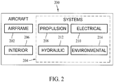
- aircraft 200 produced by aircraft manufacturing and service method 100 may include airframe 202 with a plurality of systems 204 and interior 206.
- systems 204 include one or more of propulsion system 208, electrical system 210, hydraulic system 212, and environmental system 214. Any number of other systems may be included in this example.
- propulsion system 208 electrical system 210
- hydraulic system 212 hydraulic system 212
- environmental system 214 any number of other systems may be included in this example.
- Any number of other systems may be included in this example.
- an aerospace example is shown, the principles of the disclosure may be applied to other industries, such as the automotive industry.
- Apparatus and methods embodied herein may be employed during any one or more of the stages of aircraft manufacturing and service method 100.
- components or subassemblies corresponding to component and subassembly manufacturing 106 may be fabricated or manufactured in a manner similar to components or subassemblies produced while aircraft 200 is in service.
- one or more apparatus embodiments, method embodiments, or a combination thereof may be utilized during component and subassembly manufacturing 106 and system integration 108, for example, without limitation, by substantially expediting assembly of or reducing the cost of aircraft 200.
- one or more of apparatus embodiments, method embodiments, or a combination thereof may be utilized while aircraft 200 is in service, for example, without limitation, to maintenance and service 114 may be used during system integration 108 and/or maintenance and service 114 to determine whether parts may be connected and/or mated to each other.
- NDI non-destructive inspection
- the system 300 shall consist of multiple data acquisition, ultrasonic electronic and robotic mechanical scan sub-systems in combination with corresponding probes and probe holders as well as a part immersion tank arranged as shown in Figures 3 and 4 .
- NDI system 300 includes a six-axis joint-arm (pedestal) robot 302 movable along a linear rail 304.
- pental joint-arm
- incorporation of the linear unit 304 in combination with robot 302 provides a total of seven axes of coordinated motion.
- NDI system 300 includes an operator interface 310 that includes, for example, displays 312, 314 and processing device 316.
- a shallow water tank 320 is utilized for immersion of the components to be subjected to the NDI tests.
- movement of robot 302 along rail 304, and the six axis movement of robot 302 allows for an inspection probe 330 to be moved to any location within shallow water tank 320.
- Robot 302 further incorporates an ultrasonic probe assembly changer capability as better seen in the rear view of Figure 4 .
- a probe storage device 400 includes a master side plate 402 that is attached to a face plate 410 of the robot 302. Probe storage device 400 is configured for storage of a plurality of probe assemblies as further described below.
- a linear axis carriage 430 provides space for an equipment rack 440 containing electronic units 442 that correspond to the specific ultrasonic units within the individual probe assemblies 450 disposed within probe storage device 400.
- a series of cables 460 arc incorporated into NDI system 300 that allow for the semi-permanent attachment between the electronic units 442 and respective NDI probe assemblies 450.
- the cables 460 are routed and maintained in positions that allow for the robot 302 to extract, utilize, and replace an individual probe assembly 450 with respect to probe storage device 400 while maintaining the electrical interconnection between the electronic units 442 and respective NDI probe assemblies 450.
- One of cables 460 is shown in Figure 460 as being connected to an NDI probe assembly 450 that is deployed on the robot 302.
- each probe assembly 450 consists of one or more ultrasonic inspection probes, the associated probe holder and a tool that provides a mechanical interface between the robot 302 and the probe assembly 450.
- multiple NDI probe assemblies 450 may be utilized.
- an outside magnetic guidance fixture is provided as well as a holder for the ultrasonic transducers.
- the outside guidance fixture is configured for the mechanical placement of the corresponding transducer(s) in specific locations with respect to a component being inspected by system 300.
- the outside magnetic guidance fixture is operable, via the robotic arm 302 to engage a component 470 upon which an NDI is to be performed.
- the multiple probe assemblies 450 correspond to and incorporate the various mechanical features necessary to place the various transducers in positions that allow for the complete NDI of a component or part.
- Cables connecting the ultrasonic inspection probes (e.g., pulser-receiver units) and the corresponding electronic units 442 are deployed within a cable track sufficient to enable all required electrical interconnects between the linear unit of robot 302 and the fixed equipment stand of operator interface 310.
- a cable track generally contains a 110 volt AC power line, and an Ethernet data transfer cable.
- NDI system 300 requires an operator to enter the working space of the robot 302.
- a railing system and light screen based robot guarding system is incorporated into NDI system 300 that deactivates the power to the robot 302 when the operator enters the work space.
- NDI system 300 utilizes a robotic motion control program that can be converted into executable scan programs by adding point coordinates using a teach pendant.
- the basic motion control program is designed to start at a safe "home" position, select an NDI probe assembly 450, do a series of approximately straight line scans, return the NDI probe assembly 450, and return to home.
- the home position is different for each of the parts that are tested with the NDI system 300. This is necessary so since the scanning of the parts with NDI system 300 requires a different program be executed to inspect each of the parts. Also, each of the probes will require a different scanning program due to the mechanical configuration differences.
- safety features are linked into the scanning software to prevent collisions between the probe and robot combination and one or more of the part being inspected, the tooling fixtures, and the shallow water tank 320.
- Figure 5 is a flowchart 500 illustrating robotic motion control program actions for the NDI of a part, in this example a rib, using the system 300 described herein.
- the robot 302 is programmed to start by moving 502 the effector end to a home position.
- An NDI probe assembly 450 is selected 504, based on the relevant portion of the part that is to be inspected.
- Selection of the NDI probe assembly 450 includes moving the arm of the robot 302 to the location where the relevant NDI probe assembly can be extracted from probe storage device 400.
- the extracted NDI probe assembly 450 is moved 506 to starting point P1a of scan 1. As understood, there is an interpolation between a position of the robot, its arm, and the transducer of the probe assembly 450 that is attached to the robot.
- the scan is started 508 as the system 300 issues a TTL scan start pulse and begins output of position pulses.
- the scan is executed 508, for example, by moving the effector end (the transducer within the probe) in a straight line from point P1a to end point P1b. Generally, movement is approximately along an axis.
- output of position pulses is terminated 512 and a TTL scan stop pulse is issued.
- the end effector is moved upwards to a clearance position, generally along a positive Z axis, and if the scan is not complete 514, the probe assembly, and therefore the transducer, are moved 516 to the starting position of the next scan, for example, start point P2a of scan 2.
- the remaining scans are executed, as shown in flowchart 500 until all scans associated with the particular NDI probe assembly 450 are complete 514, at which point the NDI probe assembly 450 is returned 518 to probe storage device 400, and the robot arm is returned to the home position.
- ultrasonic data is generated, with the various probe assemblies 450, in the following order with start scan and end of scan pulses for each data segment: N segments of upper radius and cap data for hat stiffeners 1 through N, N segments of lower radius and side data for hat stiffeners 1 through N, N segments of inner radius data for hat stiffeners 1 through N, M segments of web data for the composite rib, and stitched scans of the web.
- the data acquisition software operating in one embodiment of system 300 displays the data arranged as follows: N segments each containing aligned upper radius and cap, lower radius and side, and inner radius data. More particularly, the data is displayed as shown in Figures 6 through 8 , where Figure 6 includes plots 600 of upper radius and cap data for hat stiffeners, Figure 7 includes plots 700 of lower radius and side data for hat stiffeners, and Figure 8 includes plots 800 of inner radius data for hat stiffeners. Plots 600, 700, and 800 have the stringer data shown individually per transducer shoe. For NDI analysis process flow, it is desired to have the data files stitched together and displayed in one image per rib.
- Figures 9A and 9B have both the amplitude and time of flight images for the data files per ultrasonic gate as Figures 9A and 9B include plots 900 and 910 respectively illustrate composite data from the transducers in the form of amplitude data and time of flight data.
- the NDI data scans for the composite rib are stitched together into one image where amplitude and time of flight data are displayed.
- Figure 10 is an image 1000 of the amplitude data as stitched together by system 300.
- FIG. 11 is a block diagram of one embodiment of a ultrasonic subsystem interface 1100 for system 300.
- subsystem interface 1100 which is sometimes referred to as an electronic pulser-receiver system, includes three linear transducer units 1102, 1104, 1106 that are coupled to the computer 316, also providing encoder signals to robot 302.
- transducer units 1102, 1104, and 1106 are Olympus NDT Focus linear transducer units, though NDI systems could also be utilized in addition or in combination with those shown in Figure 11 .
- transducer unit 1102 is coupled to an interface box 1112, which provides an interface between transducer unit 1102 and the transducers therein, particularly an upper radius cap shoe transducer element 1122 and a low inside radius shoe transducer element 1124.
- Transducer unit 1104 is coupled to an interface box 1114, which provides an interface between transducer unit 1104 and the transducers therein, particularly a low outside radius and stringer side shoe transducer element 1132.
- Transducer unit 1106 is directly coupled to a web shoe transducer 1140.
- Figure 12 is a view of a probe assembly 450.
- a probe holder 1200 is attached to the robot 302.
- the robot 302 is programmed to engage the appropriate probe assembly 450 such that it is extracted from probe storage device 400 and placed into the shallow water tank such that a transducer 1202 mounted in probe assembly 450 is proximate the starting point referred to above.
- probe assembly 450 includes, in one embodiment, one or more guide bars 1210, 1212, are utilized to mechanically connect probe assembly halves 1220 and 1222 of probe assembly 450, with probe assembly half 1222 being movable with respect to probe assembly half 1220.
- magnets are utilized in probe assembly halves 1220 and 1222, both in an attracting mode and in a repulsion mode, to move the probe assembly half 1222 such that probe assembly 450 properly engages the portion of the composite part that is to undergo NDI testing.
- Figure 13 is a view of a probe assembly, including transducer 1302.
- Probe assembly 1300 is referred to an upper radius and cap probe and is configured for the testing of a top cap 1400 in composite part 1402, as shown in Figure 14 .
- the mechanical interface between robot 302 and probe assembly 1300 is not shown.
- the probe assembly 1500 of Figure 15 illustrates an alternative probe assembly configuration. More particularly, probe assembly 1500 incorporates a transducer 1502 positioned for testing of a side wall 1550 of a top cap 1552. Probe assembly 1500 is sometimes referred to as a lower radius and side probe holder assembly.
- Figure 16 is a bottom view of probe assembly 1500 further illustrating transducer 1502. Again for clarity, the mechanical interface between robot 302 and probe assembly 1500 is not shown.
- probe assembly 1700 of Figure 17 illustrates an alternative probe assembly configuration. More particularly, probe assembly 1700 incorporates a transducer 1702 positioned for testing of an inner radius 1750, for example of top cap 1552. Probe assembly 1700 is sometimes referred to as an inner radius probe holder assembly. The mechanical interface between robot 302 and probe assembly 1700 is not shown.
- probe assemblies of the type described herein are placed within the probe storage device 400 which is a portion of the linear unit of the robot 302.
- the three example probe assemblies described with respect to Figure 13-17 and specifically the transducers for each, can be directly and permanently cabled to the electronic units associated with the individual transducers (e.g., ultrasonic arrays) for ease of use as described above with respect to Figures 4 and 11 .
- the robot has completed the use of one probe assembly, deposits it into the probe storage device 400, and selects another probe assembly for use, a user does not have to disconnect cabling from the first to use with the second.
- the pulser-receivers of each probe assembly 450 are connected through the cable track to the data acquisition computer 316 to enable transfer of scan data.
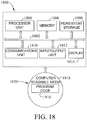
- Computer 316 and displays 312 and 314 are further illustrated in Figure 18 , which is one example of a data processing system 1800 includes communications fabric 1802, which provides communications between processor unit 1804, memory 1806, persistent storage 1808, communications unit 1810, input/output (I/O) unit 1812, and display 1814.
- Communication unit 1810 provides an interface to robot 302 and the various NDI probe assemblies 450.
- Processor unit 1804 serves to execute instructions for software that may be loaded into memory 1806.
- Processor unit 1804 may be a set of one or more processors or may be a multi-processor core, depending on the particular implementation. Further, processor unit 1804 may be implemented using one or more heterogeneous processor systems in which a main processor is present with secondary processors on a single chip. As another illustrative example, processor unit 1804 may be a symmetric multi-processor system containing multiple processors of the same type.
- Memory 1806 and persistent storage 1808 are examples of storage devices.
- a storage device is any piece of hardware that is capable of storing information either on a temporary basis and/or a permanent basis.
- Memory 1806, in these examples, may be, for example, without limitation, a random access memory or any other suitable volatile or non-volatile storage device.
- Persistent storage 1808 may take various forms depending on the particular implementation.
- persistent storage 1808 may contain one or more components or devices.
- persistent storage 1808 may be a hard drive, a flash memory, a rewritable optical disk, a rewritable magnetic tape, or some combination of the above.
- the media used by persistent storage 1808 also may be removable.
- a removable hard drive may be used for persistent storage 1808.
- Communications unit 1810 in these examples, provides for communications with other data processing systems or devices.
- communications unit 1810 is a network interface card.
- Communications unit 1810 may provide communications through the use of either or both physical and wireless communication links.
- Input/output unit 1812 allows for input and output of data with other devices that may be connected to data processing system 1800.
- input/output unit 1812 may provide a connection for user input through a keyboard and mouse. Further, input/output unit 1812 may send output to a printer.
- Display 1814 provides a mechanism to display information to a user.
- Instructions for the operating system and applications or programs are located on persistent storage 1808. These instructions may be loaded into memory 1806 for execution by processor unit 1804. The processes of the different embodiments may be performed by processor unit 1804 using computer implemented instructions, which may be located in a memory, such as memory 1806. These instructions are referred to as program code, computer usable program code, or computer readable program code that may be read and executed by a processor in processor unit 1804. The program code in the different embodiments may be embodied on different physical or tangible computer readable media, such as memory 1806 or persistent storage 1808.
- Program code 1816 is located in a functional form on computer readable media 1818 that is selectively removable and may be loaded onto or transferred to data processing system 1800 for execution by processor unit 1804.
- Program code 1816 and computer readable media 1818 form computer program product 1820 in these examples.
- computer readable media 1818 may be in a tangible form, such as, for example, an optical or magnetic disc that is inserted or placed into a drive or other device that is part of persistent storage 1808 for transfer onto a storage device, such as a hard drive that is part of persistent storage 1808.
- computer readable media 1818 also may take the form of a persistent storage, such as a hard drive, a thumb drive, or a flash memory that is connected to data processing system 1800.
- the tangible form of computer readable media 1818 is also referred to as computer recordable storage media. In some instances, computer readable media 1818 may not be removable.
- program code 1816 may be transferred to data processing system 1800 from computer readable media 1818 through a communications link to communications unit 1810 and/or through a connection to input/output unit 1812.
- the communications link and/or the connection may be physical or wireless in the illustrative examples.
- the computer readable media also may take the form of non-tangible media, such as communications links or wireless transmissions containing the program code.
- program code 1816 may be downloaded over a network to persistent storage 1808 from another device or data processing system for use within data processing system 1800.
- program code stored in a computer readable storage medium in a server data processing system may be downloaded over a network from the server to data processing system 1800.
- the data processing system providing program code 1816 may be a server computer, a client computer, or some other device capable of storing and transmitting program code 1816.
- data processing system 1800 is not meant to provide architectural limitations to the manner in which different embodiments may be implemented.
- the different illustrative embodiments may be implemented in a data processing system including components in addition to or in place of those illustrated for data processing system 1800.
- Other components shown in Figure 18 can be varied from the illustrative examples shown.
- a storage device in data processing system 1800 is any hardware apparatus that may store data.
- Memory 1806, persistent storage 1808 and computer readable media 1818 are examples of storage devices in a tangible form.
- a bus system may be used to implement communications fabric 1802 and may be comprised of one or more buses, such as a system bus or an input/output bus.
- the bus system may be implemented using any suitable type of architecture that provides for a transfer of data between different components or devices attached to the bus system.
- a communications unit may include one or more devices used to transmit and receive data, such as a modem or a network adapter.
- a memory may be, for example, without limitation, memory 1806 or a cache such as that found in an interface and memory controller hub that may be present in communications fabric 1802.
Description
- The field of the disclosure relates generally to non-destructive inspection (NDI) equipment and processes, and more particularly to NDI systems and methods that incorporate interchangeable probes.
- Part of the fabrication process for composite parts, for example, primary structural composite parts and composite rib parts for an aircraft, includes a non-destructive inspection (NDI) process. However, in one example fabrication, the composite ribs are not identical to one another. That is, rib number two is a completely different size, for example, than rib number five. Further in this example fabrication, ribs destined for the right side of the aircraft are different from the ribs destined for the left side of the aircraft.
- Currently, NDI is performed using an x-y-z scanner with NDI probes attached to an end of the effector. The NDI probes are interchanged by an operator to perform the various NDI tests associated with a part. Separate inspection systems for individual components, and operator interchanging of probes, is cost prohibitive. Further, as much NDI is performed in deep water tanks, the expense associated with such tanks is a cost that companies would like to avoid.
- Robotic inspection with ultrasonic NDI systems has always had limitations due to the sensitivity of the probe heads to electrical connection/disconnection. As described above, however, having a different probe head for every inspection condition would result in a heavy and complex end effector that would impact the size and cost of the robot.
-
JP 2005 106654 A -
US 2008/210009 A1 discloses an automatic ultrasonic examination device that includes an ultrasonic test instrument, a robot arm, and a control device. The ultrasonic test instrument includes an ultrasonic probe to send ultrasonic and detecting reflected waves while being in contact with the spot-welded portion, and an ultrasonic lest instrument main device connected to the ultrasonic probe to convert the reflected wave detection signals received from the ultrasonic probe into test information. The control device includes a real center location computing unit to identify a real center location of the spot-welded portion with reference to pieces of test information obtained around a preset tentative center location of the spot-welded portion, and a determination unit to check quality of the spot-welded portion with reference to test information obtained at the real center location. -
EP 1 744 157 A2 - Aspects of the invention are set out in the independent claims. In one example useful for understanding the disclosure, a non-destructive inspection (NDI) device is provided that includes a robotic arm, a storage device proximate the robotic arm, and a plurality of NDI probe assemblies disposed within the storage device. Each NDI probe assembly includes at least one transducer operable for NDI of a part and a tool operable as a mechanical interface between the robotic arm and the corresponding NDI probe assembly. Each NDI probe assembly is configured for a specific NDI task, for NDI of a part, and the robotic arm is operable for selectively engaging the tools and movement of the probe assemblies for the NDI of at least a portion of a part.
- A method for non-destructive inspection (NDI) of a part that incorporates multiple structural features is provided. The method includes selecting an NDI probe assembly from a plurality of NDI probe assemblies staged proximate a robotic arm, the selection based upon one or more of the multiple structural features associated with the part to be inspected, engaging the selected NDI probe assembly with the robotic arm, moving the robotic arm from the staging area to an inspection area such that the selected NDI probe assembly engages the part to be inspected proximate one of the structural features of the part that is associated with the selected NDI probe assembly, guiding the NDI probe assembly along the part in a defined path while a transducer associated with the selected NDI probe assembly provides and receives signals associated with NDI, returning the selected NDI probe assembly to the staging area, and repeating the selecting, engaging, moving guiding, and returning steps for at least one more NDI probe assembly staged proximate the robotic arm, each NDI probe assembly associated with at least one different structural feature of the part and communicatively coupled to a corresponding electronic assembly both when the NDI probe assembly is deployed on the robotic arm and when staged proximate the robotic arm.
- In still another example useful for understanding the disclosure, a non-destructive inspection (NDI) system is provided that includes a linear track, a carriage operable to move along the linear track, a robotic arm mounted to the carriage, a storage device mounted to the carriage, a plurality of electronic assemblies mounted to the carriage, and a plurality of NDI probe assemblies disposed within the storage device communicatively coupled to a corresponding electrical assembly. Each of the electronic assemblies is operable to provide signals for the operation of specific transducers utilized in NDI. Each NDI probe assembly includes at least one transducer operable for NDI of a component and a mechanical interface to the robotic arm, for NDI of a component having a plurality of structural features. The system is programmed to operate the robotic arm to select, engage and remove one of the NDI probe assemblies from the storage device for NDI of at least one specific structural feature, place the removed NDI probe assembly in a position with respect to the component such that the at least one transducer associated with the NDI probe assembly is proximate a start position for NDI of the at least one structural feature, execute a command to start the NDI, move the removed NDI probe assembly along at least one defined scan path using at least one of the carriage and the robotic arm, and return the removed NDI probe assembly to the storage device upon completion of the NDI of the structural features of the component associated with the removed NDI assembly. The system is further programmed to repeat the operation, placement, execution, movement and returning for each of the NDI probe assemblies within the storage device needed to complete a specific set of NDI tests for a plurality of structural features associated with the component.
- Other examples useful for understanding the disclosure include:
- A. A non-destructive inspection (NDI) system comprising:
- a linear track comprising a carriage operable to move along said linear track;
- a robotic arm mounted to said carriage;
- a storage device mounted to said carriage;
- a plurality of electronic assemblies mounted to said carriage, each of said electronic assemblies operable to provide signals for the operation of specific transducers utilized in NDI; and
- a plurality of NDI probe assemblies disposed within said storage device communicatively coupled to a corresponding said electrical assembly, each NDI probe assembly comprising at least one transducer operable for NDI of a component and a mechanical interface to said robotic arm, for NDI of a component having a plurality of structural features, said system programmed to:
- operate said robotic arm to select, engage and remove one of said NDI probe assemblies from said storage device for NDI of at least one specific structural feature,
- place the removed NDI probe assembly in a position with respect to the component such that the at least one transducer associated with the said NDI probe assembly is proximate a start position for NDI of the at least one structural feature;
- execute a command to start the NDI;
- move the removed NDI probe assembly along at least one defined scan path using at least one of said carriage and said robotic arm;
- return the removed NDI probe assembly to said storage device upon completion of the NDI of the structural features of the component associated with the removed NDI assembly; and
- said system further programmed to repeat the operation, placement, execution, movement and returning for each of said NDI probe assemblies within said storage device needed to complete a specific set of NDI tests for a plurality of structural features associated with the component.
- B.. The NDI system of Paragraph A wherein each said NDI probe assembly comprises:
- a first probe assembly half;
- a second probe assembly half; and
- at least one guide bar utilized to mechanically connect said probe assembly halves, said second probe assembly half being movable with respect to said first probe assembly half, each said probe assembly half comprising at least one magnet disposed therein, said magnets operable to move said second probe assembly half such that said NDI probe assembly properly engages the portion of the component that is to undergo NDI.
- C. The NDI system of Paragraph A further comprising a shallow water tank proximate said linear track, said linear track positioned proximate said shallow water tank such that said robotic arm is capable of traveling the length of said shallow water tank along said linear track.
- D. The NDI system of Paragraph A wherein said electronic assemblies are communicatively coupled to the corresponding said transducers both when said NDI probe assemblies are deployed on said robotic arm and when disposed within said storage device.
- E. The NDI system of Paragraph A wherein said NDI probe assemblies comprise:
- an upper radius and cap probe assembly;
- a lower radius and side probe assembly; and
- an inner radius probe assembly.
- The features, functions, and advantages that have been discussed can be achieved independently in various embodiments or may be combined in yet other embodiments further details of which can be seen with reference to the following description and drawings.
-
-
Figure 1 is a flow diagram of an aircraft production and service methodology. -
Figure 2 is a block diagram of an aircraft. -
Figure 3 is a front view depiction of a non-destructive inspection (NDI) system according to one embodiment. -
Figure 4 is a rear view depiction of the NDI system ofFigure 3 . -
Figure 5 is a flowchart illustrating robotic motion control program actions for the NDI of a part using the system ofFigures 3 and4 . -
Figure 6 includes plots of upper radius and cap data for hat stiffeners. -
Figure 7 includes plots of lower radius and side data for hat stiffeners. -
Figure 8 includes plots of inner radius data for hat stiffeners. -
Figure 9A illustrates composite data from NDI transducers in the form of amplitude data. -
Figure 9B illustrates composite data from NDI transducers in the form of time of flight data. -
Figure 10 is an image of amplitude data as stitched together by the system ofFigures 3 and4 . -
Figure 11 is a block diagram of one embodiment of an ultrasonic subsystem interface for the system ofFigures 3 and4 . -
Figure 12 is a view of a probe assembly. -
Figure 13 is a view of an upper radius and cap probe assembly. -
Figure 14 is an alternate view of the upper radius and cap probe assembly ofFigure 13 . -
Figure 15 is a view of a lower radius and side probe holder assembly. -
Figure 16 is an alternate view of the lower radius and side probe holder assembly ofFigure 15 . -
Figure 17 illustrates an inner radius probe holder assembly. -
Figure 18 is a diagram of a data processing system. - The described embodiments are directed to a non-destructive inspection (NDI) system that performs NDI of multiple ribs and stringers for an aircraft, though the embodiments should not be construed to be so limited. The described embodiments perform the NDI in a shallow water tank, which is more cost efficient than deep water tank NDI testing.
- In an embodiment, the NDI system incorporates a robotic arm and multiple NDI probe assemblies that can be interchanged on the robotic arm which allows for implementation of NDI of composite ribs of different design. More specifically, the programming associated with operation of the robotic arm and the multiple NDI probe assemblies yield good data scans and provides efficient NDI scans for multiple rib configurations. Further, the described NDI system embodiments are (estimated >5X) faster and more reliable than NDI systems currently utilized to inspect similar structures. The NDI process is automated by the embodiments described herein, allowing for a reduction in the number of NDI operators.
- To accomplish the above mentioned improvements, the NDI system incorporates multiple NDI probes assemblies for inspection of the various structural features of the various composite parts. Such probe assemblies are incorporated into an automated system for NDI. The NDI system further incorporates a robotic arm that facilitates NDI probe selection, positioning and scanning. The usage of multiple NDI probe assemblies with a single robotic arm device results in reduced cost as multiple NDI systems and/or robotic systems for the probe scanning of the various composite structural parts are not needed.
- In one embodiment, technical effects of the methods, systems, and computer-readable media described herein include at least one of: (a) providing a lean and efficient non-destructive inspection system and method for a complex composite part, (b) selecting an NDI probe assembly from a plurality of NDI probe assemblies staged proximate a robotic arm, the selection based upon one or more of the multiple structural features associated with the part to be inspected, (c) engaging the selected NDI probe assembly with the robotic arm, (d) moving the robotic arm from the staging area to an inspection area such that the selected NDI probe assembly engages the part to be inspected proximate one of the structural features of the part that is associated with the selected NDI probe assembly, (e) guiding the NDI probe assembly along the part in a defined path while a transducer associated with the selected NDI probe assembly provides and receives signals associated with NDI, (f) returning the selected NDI probe assembly to the staging area, and (g) repeating the selecting, engaging, moving guiding, and returning steps for at least one more NDI probe assembly staged proximate the robotic arm, each NDI probe assembly associated with at least one different structural feature of the part.
- As used herein, an element or step recited in the singular and proceeded with the word "a" or "an" should be understood as not excluding plural elements or steps unless such exclusion is explicitly recited. Furthermore, references to "one embodiment" of the present invention or the "exemplary embodiment" are not intended to be interpreted as excluding the existence of additional embodiments that also incorporate the recited features.
- Referring more particularly to the drawings, embodiments of the disclosure may be described in the context of aircraft manufacturing and
service method 100 as shown inFigure 1 and anaircraft 200 as shown inFigure 2 . During pre-production, aircraft manufacturing andservice method 100 may include specification anddesign 102 ofaircraft 200 andmaterial procurement 104. - During production, component and
subassembly manufacturing 106 andsystem integration 108 ofaircraft 200 takes place. Thereafter,aircraft 200 may go through certification anddelivery 110 in order to be placed inservice 112. While in service by a customer,aircraft 200 is scheduled for routine maintenance and service 114 (which may also include modification, reconfiguration, refurbishment, and so on). - Each of the processes of aircraft manufacturing and
service method 100 may be performed or carried out by a system integrator, a third party, and/or an operator (e.g., a customer). For the purposes of this description, a system integrator may include, without limitation, any number of aircraft manufacturers and major-system subcontractors; a third party may include, for example, without limitation, any number of venders, subcontractors, and suppliers; and an operator may be an airline, leasing company, military entity, service organization, and so on. - As shown in
Figure 2 ,aircraft 200 produced by aircraft manufacturing andservice method 100 may includeairframe 202 with a plurality ofsystems 204 and interior 206. Examples ofsystems 204 include one or more ofpropulsion system 208,electrical system 210,hydraulic system 212, andenvironmental system 214. Any number of other systems may be included in this example. Although an aerospace example is shown, the principles of the disclosure may be applied to other industries, such as the automotive industry. - Apparatus and methods embodied herein may be employed during any one or more of the stages of aircraft manufacturing and
service method 100. For example, without limitation, components or subassemblies corresponding to component andsubassembly manufacturing 106 may be fabricated or manufactured in a manner similar to components or subassemblies produced whileaircraft 200 is in service. - Also, one or more apparatus embodiments, method embodiments, or a combination thereof may be utilized during component and
subassembly manufacturing 106 andsystem integration 108, for example, without limitation, by substantially expediting assembly of or reducing the cost ofaircraft 200. Similarly, one or more of apparatus embodiments, method embodiments, or a combination thereof may be utilized whileaircraft 200 is in service, for example, without limitation, to maintenance andservice 114 may be used duringsystem integration 108 and/or maintenance andservice 114 to determine whether parts may be connected and/or mated to each other. - The description of the different advantageous embodiments has been presented for purposes of illustration and description, and is not intended to be exhaustive or limited to the embodiments in the form disclosed. Many modifications and variations will be apparent to those of ordinary skill in the art. Further, different advantageous embodiments may provide different advantages as compared to other advantageous embodiments. The embodiment or embodiments selected are chosen and described in order to best explain the principles of the embodiments, the practical application, and to enable others of ordinary skill in the art to understand the disclosure for various embodiments with various modifications as are suited to the particular use contemplated.
- Turning now to
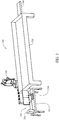
Figure 3 , a diagram of a non-destructive inspection (NDI)system 300 is depicted in accordance with an illustrative embodiment. Thesystem 300 shall consist of multiple data acquisition, ultrasonic electronic and robotic mechanical scan sub-systems in combination with corresponding probes and probe holders as well as a part immersion tank arranged as shown inFigures 3 and4 . More specifically,NDI system 300 includes a six-axis joint-arm (pedestal)robot 302 movable along alinear rail 304. In the configuration ofFigure 3 , incorporation of thelinear unit 304 in combination withrobot 302 provides a total of seven axes of coordinated motion. As shown inFigure 3 ,NDI system 300 includes anoperator interface 310 that includes, for example, displays 312, 314 andprocessing device 316. Ashallow water tank 320 is utilized for immersion of the components to be subjected to the NDI tests. As can be understood fromFigure 3 , movement ofrobot 302 alongrail 304, and the six axis movement ofrobot 302 allows for an inspection probe 330 to be moved to any location withinshallow water tank 320. -
Robot 302 further incorporates an ultrasonic probe assembly changer capability as better seen in the rear view ofFigure 4 . Referring toFigure 4 , aprobe storage device 400 includes amaster side plate 402 that is attached to a face plate 410 of therobot 302.Probe storage device 400 is configured for storage of a plurality of probe assemblies as further described below. - A
linear axis carriage 430 provides space for anequipment rack 440 containingelectronic units 442 that correspond to the specific ultrasonic units within theindividual probe assemblies 450 disposed withinprobe storage device 400. To address the issues described herein with the connecting, disconnecting, and reconnecting ofprobe assemblies 450 to their respective supportingelectronics units 442, a series ofcables 460 arc incorporated intoNDI system 300 that allow for the semi-permanent attachment between theelectronic units 442 and respectiveNDI probe assemblies 450. In use, thecables 460 are routed and maintained in positions that allow for therobot 302 to extract, utilize, and replace anindividual probe assembly 450 with respect toprobe storage device 400 while maintaining the electrical interconnection between theelectronic units 442 and respectiveNDI probe assemblies 450. One ofcables 460 is shown in Figure 460 as being connected to anNDI probe assembly 450 that is deployed on therobot 302. - In an embodiment, each
probe assembly 450 consists of one or more ultrasonic inspection probes, the associated probe holder and a tool that provides a mechanical interface between therobot 302 and theprobe assembly 450. In the NDI of a lower inside radius of an aircraft stringer, for example, multipleNDI probe assemblies 450 may be utilized. In oneNDI probe assembly 450, for example, an outside magnetic guidance fixture is provided as well as a holder for the ultrasonic transducers. The outside guidance fixture is configured for the mechanical placement of the corresponding transducer(s) in specific locations with respect to a component being inspected bysystem 300. Specifically, the outside magnetic guidance fixture is operable, via therobotic arm 302 to engage acomponent 470 upon which an NDI is to be performed. As such, themultiple probe assemblies 450 correspond to and incorporate the various mechanical features necessary to place the various transducers in positions that allow for the complete NDI of a component or part. - Cables connecting the ultrasonic inspection probes (e.g., pulser-receiver units) and the corresponding
electronic units 442 are deployed within a cable track sufficient to enable all required electrical interconnects between the linear unit ofrobot 302 and the fixed equipment stand ofoperator interface 310. As an example, a cable track generally contains a 110 volt AC power line, and an Ethernet data transfer cable. - Operation of
NDI system 300 requires an operator to enter the working space of therobot 302. In one embodiment, a railing system and light screen based robot guarding system is incorporated intoNDI system 300 that deactivates the power to therobot 302 when the operator enters the work space. -
NDI system 300 utilizes a robotic motion control program that can be converted into executable scan programs by adding point coordinates using a teach pendant. The basic motion control program is designed to start at a safe "home" position, select anNDI probe assembly 450, do a series of approximately straight line scans, return theNDI probe assembly 450, and return to home. In embodiments, the home position is different for each of the parts that are tested with theNDI system 300. This is necessary so since the scanning of the parts withNDI system 300 requires a different program be executed to inspect each of the parts. Also, each of the probes will require a different scanning program due to the mechanical configuration differences. In embodiments of the scanning programs, safety features are linked into the scanning software to prevent collisions between the probe and robot combination and one or more of the part being inspected, the tooling fixtures, and theshallow water tank 320. -
Figure 5 is aflowchart 500 illustrating robotic motion control program actions for the NDI of a part, in this example a rib, using thesystem 300 described herein. Therobot 302 is programmed to start by moving 502 the effector end to a home position. AnNDI probe assembly 450 is selected 504, based on the relevant portion of the part that is to be inspected. Selection of theNDI probe assembly 450 includes moving the arm of therobot 302 to the location where the relevant NDI probe assembly can be extracted fromprobe storage device 400. Based on the program being executed, the extractedNDI probe assembly 450 is moved 506 to starting point P1a ofscan 1. As understood, there is an interpolation between a position of the robot, its arm, and the transducer of theprobe assembly 450 that is attached to the robot. - The scan is started 508 as the
system 300 issues a TTL scan start pulse and begins output of position pulses. The scan is executed 508, for example, by moving the effector end (the transducer within the probe) in a straight line from point P1a to end point P1b. Generally, movement is approximately along an axis. As the effector end reaches end point P1b, output of position pulses is terminated 512 and a TTL scan stop pulse is issued. The end effector is moved upwards to a clearance position, generally along a positive Z axis, and if the scan is not complete 514, the probe assembly, and therefore the transducer, are moved 516 to the starting position of the next scan, for example, start point P2a ofscan 2. The remaining scans are executed, as shown inflowchart 500 until all scans associated with the particularNDI probe assembly 450 are complete 514, at which point theNDI probe assembly 450 is returned 518 to probestorage device 400, and the robot arm is returned to the home position. - In one embodiment, and relevant to a specific set of composite components to be inspected, ultrasonic data is generated, with the
various probe assemblies 450, in the following order with start scan and end of scan pulses for each data segment: N segments of upper radius and cap data forhat stiffeners 1 through N, N segments of lower radius and side data forhat stiffeners 1 through N, N segments of inner radius data forhat stiffeners 1 through N, M segments of web data for the composite rib, and stitched scans of the web. - The data acquisition software operating in one embodiment of
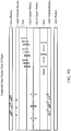
system 300 displays the data arranged as follows: N segments each containing aligned upper radius and cap, lower radius and side, and inner radius data. More particularly, the data is displayed as shown inFigures 6 through 8 , whereFigure 6 includesplots 600 of upper radius and cap data for hat stiffeners,Figure 7 includesplots 700 of lower radius and side data for hat stiffeners, andFigure 8 includesplots 800 of inner radius data for hat stiffeners.Plots - The data after it has been acquired for all the probes for a stringer shall display the data as a composite image.
Figures 9A and9B have both the amplitude and time of flight images for the data files per ultrasonic gate asFigures 9A and9B include plots 900 and 910 respectively illustrate composite data from the transducers in the form of amplitude data and time of flight data. - In one embodiment, the NDI data scans for the composite rib are stitched together into one image where amplitude and time of flight data are displayed.
Figure 10 is an image 1000 of the amplitude data as stitched together bysystem 300. -
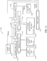
Figure 11 is a block diagram of one embodiment of aultrasonic subsystem interface 1100 forsystem 300. In the illustrated embodiment,subsystem interface 1100, which is sometimes referred to as an electronic pulser-receiver system, includes threelinear transducer units computer 316, also providing encoder signals torobot 302. In a specific embodiment,transducer units Figure 11 . As shown inFigure 11 ,transducer unit 1102 is coupled to aninterface box 1112, which provides an interface betweentransducer unit 1102 and the transducers therein, particularly an upper radius capshoe transducer element 1122 and a low inside radiusshoe transducer element 1124.Transducer unit 1104 is coupled to aninterface box 1114, which provides an interface betweentransducer unit 1104 and the transducers therein, particularly a low outside radius and stringer sideshoe transducer element 1132.Transducer unit 1106 is directly coupled to aweb shoe transducer 1140. -
Figure 12 is a view of aprobe assembly 450. In operation, aprobe holder 1200 is attached to therobot 302. Therobot 302 is programmed to engage theappropriate probe assembly 450 such that it is extracted fromprobe storage device 400 and placed into the shallow water tank such that atransducer 1202 mounted inprobe assembly 450 is proximate the starting point referred to above. Further,probe assembly 450 includes, in one embodiment, one ormore guide bars probe assembly halves probe assembly 450, withprobe assembly half 1222 being movable with respect to probeassembly half 1220. In one embodiment, magnets are utilized inprobe assembly halves probe assembly half 1222 such thatprobe assembly 450 properly engages the portion of the composite part that is to undergo NDI testing. -
Figure 13 is a view of a probe assembly, includingtransducer 1302.Probe assembly 1300 is referred to an upper radius and cap probe and is configured for the testing of atop cap 1400 incomposite part 1402, as shown inFigure 14 . For clarity, the mechanical interface betweenrobot 302 andprobe assembly 1300 is not shown. - The
probe assembly 1500 ofFigure 15 illustrates an alternative probe assembly configuration. More particularly,probe assembly 1500 incorporates atransducer 1502 positioned for testing of aside wall 1550 of atop cap 1552.Probe assembly 1500 is sometimes referred to as a lower radius and side probe holder assembly.Figure 16 is a bottom view ofprobe assembly 1500 further illustratingtransducer 1502. Again for clarity, the mechanical interface betweenrobot 302 andprobe assembly 1500 is not shown. - The
probe assembly 1700 ofFigure 17 illustrates an alternative probe assembly configuration. More particularly,probe assembly 1700 incorporates atransducer 1702 positioned for testing of aninner radius 1750, for example oftop cap 1552.Probe assembly 1700 is sometimes referred to as an inner radius probe holder assembly. The mechanical interface betweenrobot 302 andprobe assembly 1700 is not shown. - In use, probe assemblies of the type described herein are placed within the
probe storage device 400 which is a portion of the linear unit of therobot 302. With such a configuration, the three example probe assemblies described with respect toFigure 13-17 , and specifically the transducers for each, can be directly and permanently cabled to the electronic units associated with the individual transducers (e.g., ultrasonic arrays) for ease of use as described above with respect toFigures 4 and11 . Specifically, when the robot has completed the use of one probe assembly, deposits it into theprobe storage device 400, and selects another probe assembly for use, a user does not have to disconnect cabling from the first to use with the second. The pulser-receivers of eachprobe assembly 450 are connected through the cable track to thedata acquisition computer 316 to enable transfer of scan data. -
Computer 316 anddisplays Figure 18 , which is one example of adata processing system 1800 includescommunications fabric 1802, which provides communications betweenprocessor unit 1804,memory 1806,persistent storage 1808,communications unit 1810, input/output (I/O)unit 1812, anddisplay 1814.Communication unit 1810 provides an interface torobot 302 and the variousNDI probe assemblies 450. -
Processor unit 1804 serves to execute instructions for software that may be loaded intomemory 1806.Processor unit 1804 may be a set of one or more processors or may be a multi-processor core, depending on the particular implementation. Further,processor unit 1804 may be implemented using one or more heterogeneous processor systems in which a main processor is present with secondary processors on a single chip. As another illustrative example,processor unit 1804 may be a symmetric multi-processor system containing multiple processors of the same type. -
Memory 1806 andpersistent storage 1808 are examples of storage devices. A storage device is any piece of hardware that is capable of storing information either on a temporary basis and/or a permanent basis.Memory 1806, in these examples, may be, for example, without limitation, a random access memory or any other suitable volatile or non-volatile storage device.Persistent storage 1808 may take various forms depending on the particular implementation. For example, without limitation,persistent storage 1808 may contain one or more components or devices. For example,persistent storage 1808 may be a hard drive, a flash memory, a rewritable optical disk, a rewritable magnetic tape, or some combination of the above. The media used bypersistent storage 1808 also may be removable. For example, without limitation, a removable hard drive may be used forpersistent storage 1808. -
Communications unit 1810, in these examples, provides for communications with other data processing systems or devices. In these examples,communications unit 1810 is a network interface card.Communications unit 1810 may provide communications through the use of either or both physical and wireless communication links. - Input/
output unit 1812 allows for input and output of data with other devices that may be connected todata processing system 1800. For example, without limitation, input/output unit 1812 may provide a connection for user input through a keyboard and mouse. Further, input/output unit 1812 may send output to a printer.Display 1814 provides a mechanism to display information to a user. - Instructions for the operating system and applications or programs are located on
persistent storage 1808. These instructions may be loaded intomemory 1806 for execution byprocessor unit 1804. The processes of the different embodiments may be performed byprocessor unit 1804 using computer implemented instructions, which may be located in a memory, such asmemory 1806. These instructions are referred to as program code, computer usable program code, or computer readable program code that may be read and executed by a processor inprocessor unit 1804. The program code in the different embodiments may be embodied on different physical or tangible computer readable media, such asmemory 1806 orpersistent storage 1808. -
Program code 1816 is located in a functional form on computerreadable media 1818 that is selectively removable and may be loaded onto or transferred todata processing system 1800 for execution byprocessor unit 1804.Program code 1816 and computerreadable media 1818 formcomputer program product 1820 in these examples. In one example, computerreadable media 1818 may be in a tangible form, such as, for example, an optical or magnetic disc that is inserted or placed into a drive or other device that is part ofpersistent storage 1808 for transfer onto a storage device, such as a hard drive that is part ofpersistent storage 1808. In a tangible form, computerreadable media 1818 also may take the form of a persistent storage, such as a hard drive, a thumb drive, or a flash memory that is connected todata processing system 1800. The tangible form of computerreadable media 1818 is also referred to as computer recordable storage media. In some instances, computerreadable media 1818 may not be removable. - Alternatively,
program code 1816 may be transferred todata processing system 1800 from computerreadable media 1818 through a communications link tocommunications unit 1810 and/or through a connection to input/output unit 1812. The communications link and/or the connection may be physical or wireless in the illustrative examples. The computer readable media also may take the form of non-tangible media, such as communications links or wireless transmissions containing the program code. - In some illustrative embodiments,
program code 1816 may be downloaded over a network topersistent storage 1808 from another device or data processing system for use withindata processing system 1800. For instance, program code stored in a computer readable storage medium in a server data processing system may be downloaded over a network from the server todata processing system 1800. The data processing system providingprogram code 1816 may be a server computer, a client computer, or some other device capable of storing and transmittingprogram code 1816. - The different components illustrated for
data processing system 1800 are not meant to provide architectural limitations to the manner in which different embodiments may be implemented. The different illustrative embodiments may be implemented in a data processing system including components in addition to or in place of those illustrated fordata processing system 1800. Other components shown inFigure 18 can be varied from the illustrative examples shown. - As one example, a storage device in
data processing system 1800 is any hardware apparatus that may store data.Memory 1806,persistent storage 1808 and computerreadable media 1818 are examples of storage devices in a tangible form. - In another example, a bus system may be used to implement
communications fabric 1802 and may be comprised of one or more buses, such as a system bus or an input/output bus. Of course, the bus system may be implemented using any suitable type of architecture that provides for a transfer of data between different components or devices attached to the bus system. Additionally, a communications unit may include one or more devices used to transmit and receive data, such as a modem or a network adapter. Further, a memory may be, for example, without limitation,memory 1806 or a cache such as that found in an interface and memory controller hub that may be present incommunications fabric 1802.
Claims (13)
- A non-destructive inspection "NDI" system comprising:a robotic arm (302);a storage device (400) proximate said robotic arm (302);a processor unit (1804); anda plurality of NDI probe assemblies (450) disposed within said storage device (400), each NDI probe assembly (450) comprising at least one transducer (1202) operable for NDI of a part (1402) and a tool operable as a mechanical interface between said robotic arm (302) and the corresponding said NDI probe assembly (450), each said NDI probe assembly (450) configured for a specific NDI task, for NDI of a part (1402), said robotic arm (302) operable by the processor unit (1804) to select, engage and remove one of said NDI probe assemblies (450) from said storage device (400) for the NDI of at least a portion of the part (1402), wherein each said NDI probe assembly (450) comprises:a holder (1200) for the corresponding said transducers (1202); andan outside magnetic guidance fixture operable via said robotic arm (302) to engage a component (470) upon which an NDI is to be performed and place said transducers (1202) in a position for the NDI of a part (1402),wherein said outside magnetic guidance fixture comprises:a first probe assembly half (1220);a second probe assembly half (1222); andat least one guide bar (1210) for mechanically connecting said probe assembly halves, said second probe assembly half (1222) being movable with respect to said first probe assembly half (1220), each said probe assembly half comprising at least one magnet disposed therein, said magnets operable to move said second probe assembly half such that said NDI probe assembly (450) properly engages the portion of the part (1402) that is to undergo NDI.
- The NDI system of Claim 1 further comprising a plurality of electronic assemblies associated with corresponding said transducers (1202), said electronic assemblies communicatively coupled to the corresponding said transducers (1202) both when the NDI probe assemblies (450) are deployed on said robotic arm (302) and when disposed within said storage device (400).
- The NDI system of Claim 2 further comprising a linear track, said robotic arm and said electronic assemblies movable along said linear track thereby allowing said transducers (1202) to maintain the communicative coupling to the corresponding said electrical assembly both during use and when placed within said storage device (400).
- The NDI system of Claim 3 further comprising a shallow water tank (320), said linear track positioned proximate said shallow water tank (320) such that said robotic arm (302) is capable of traveling the length of said shallow water tank (320).
- The NDI system of Claim 1 wherein said robotic arm (302) comprises a six-axis joint arm pedestal robot.
- The NDI system of Claim 1 wherein said outside magnetic guidance fixture comprises a mechanical interface operable for the placement of said transducers (1202) in positions that allow for the NDI of a part.
- A method for non-destructive inspection "NDI" of a part (1402) that incorporates multiple structural features, said method comprising:selecting an NDI probe assembly (450) from a plurality of NDI probe assemblies (450) staged proximate a robotic arm (302), the selection based upon one or more of the multiple structural features associated with the part (1402) to be inspected;engaging the selected NDI probe assembly (450) with the robotic arm (302);moving the robotic arm (302) from the staging area to an inspection area such that the selected NDI probe assembly (450) engages the part to be inspected proximate one of the structural features of the part (1402) that is associated with the selected NDI probe assembly (450);guiding the NDI probe assembly (450) along the part in a defined path while a transducer (1202) associated with the selected NDI probe assembly (450) provides and receives signals associated with NDI;returning the selected NDI probe assembly (450) to the staging area; andrepeating the selecting, engaging, moving guiding, and returning steps for at least one more NDI probe assembly (450) staged proximate the robotic arm (302), each NDI probe assembly (450) associated with at least one different structural feature of the part (1402) and communicatively coupled to a corresponding electronic assembly both when the NDI probe assembly (450) is deployed on the robotic arm (302) and when staged proximate the robotic arm (302), wherein each said NDI probe assembly (450) comprises a holder (1200) for the corresponding said transducers (1202) and an outside magnetic guidance fixture operable via said robotic arm (302) to engage a component (470) upon which an NDI is to be performed and place said transducers (1202) in a position for NDI of the part (1402),wherein said outside magnetic guidance fixture comprises:a first probe assembly half (1220);a second probe assembly half (1222); andat least one guide bar (1210) for mechanically connecting said probe assembly halves, said second probe assembly half (1222) being movable with respect to said first probe assembly half (1220), each said probe assembly half comprising at least one magnet disposed therein, said magnets operable to move said second probe assembly half such that said NDI probe assembly (450) properly engages the portion of the part (1402) that is to undergo NDI.
- The method according to Claim 7 further comprising moving the robotic arm (302) along a linear guide proximate the part.
- The method according to Claim 8 further comprising disposing the plurality of NDI probe assemblies (450) proximate a storage device (400) proximate the robotic arm (302), the storage device (400) mechanically coupled to the robotic arm (302) for movement along the linear track.
- The method according to Claim 7 wherein moving the robotic arm (302) from the staging area to an inspection area comprises moving the selected NDI probe assembly (450) into a position within a shallow water tank (320), the part (1402) to be inspected disposed within the shallow water tank (320).
- The method according to Claim 7 wherein guiding the NDI probe assembly (450) along the part in a defined path comprises at least one of:moving the robotic arm (302) along a linear track proximate the part (1402) undergoing the NDI; andmoving a six-axis joint arm pedestal associated with the robotic arm (302).
- The method according to Claim 7 wherein engaging the selected NDI probe assembly (450) with the robotic arm (302) comprises mechanically engaging the guidance fixture within which at least one transducer (1202) is mounted.
- The method according to Claim 11 wherein moving the robotic arm (302) from the staging area to an inspection area further comprises engaging the part to be inspected with the guidance fixture such that said transducer (1202) within the guidance fixture is properly placed proximate the part (1402) for an initial NDI scan.
Applications Claiming Priority (1)
| Application Number | Priority Date | Filing Date | Title |
|---|---|---|---|
| US13/179,878 US8573076B2 (en) | 2011-07-11 | 2011-07-11 | Non-destructive inspection systems and methods that incorporate interchangeable probes |
Publications (3)
| Publication Number | Publication Date |
|---|---|
| EP2546640A2 EP2546640A2 (en) | 2013-01-16 |
| EP2546640A3 EP2546640A3 (en) | 2017-07-12 |
| EP2546640B1 true EP2546640B1 (en) | 2021-03-10 |
Family
ID=47048943
Family Applications (1)
| Application Number | Title | Priority Date | Filing Date |
|---|---|---|---|
| EP12175999.7A Active EP2546640B1 (en) | 2011-07-11 | 2012-07-11 | Non-destructive inspection systems and methods with interchangeable probes |
Country Status (6)
| Country | Link |
|---|---|
| US (2) | US8573076B2 (en) |
| EP (1) | EP2546640B1 (en) |
| JP (1) | JP5954779B2 (en) |
| KR (1) | KR101913432B1 (en) |
| CN (1) | CN102879479B (en) |
| CA (1) | CA2776441C (en) |
Families Citing this family (17)
| Publication number | Priority date | Publication date | Assignee | Title |
|---|---|---|---|---|
| US8833169B2 (en) * | 2011-12-09 | 2014-09-16 | General Electric Company | System and method for inspection of a part with dual multi-axis robotic devices |
| US9470658B2 (en) * | 2013-03-12 | 2016-10-18 | The Boeing Company | Self-contained holonomic tracking method and apparatus for non-destructive inspection |
| US9746445B2 (en) * | 2013-04-16 | 2017-08-29 | The Boeing Company | Apparatus for automated non-destructive inspection of airfoil-shaped bodies |
| FR3015706B1 (en) * | 2013-12-23 | 2016-02-05 | Eads Europ Aeronautic Defence | REFERENCE OF THE TOOL CENTER AND THE ORIENTATION OF AN ACOUSTIC PROBE IN A REFERENCE MARK, BY ULTRASONIC METHOD |
| CN104198591A (en) * | 2014-08-28 | 2014-12-10 | 宁夏共享集团有限责任公司 | Automatic ultrasonic detection device applicable to casting of complex structure |
| US9746447B2 (en) * | 2014-10-30 | 2017-08-29 | The Boeing Company | Apparatuses, systems, and methods for inspecting a component |
| US9664652B2 (en) | 2014-10-30 | 2017-05-30 | The Boeing Company | Non-destructive ultrasonic inspection apparatus, systems, and methods |
| US10060475B2 (en) * | 2014-12-24 | 2018-08-28 | Teradyne, Inc. | Braking system |
| US10371646B2 (en) * | 2016-09-19 | 2019-08-06 | The Boeing Company | Method and system for automated data collection and part validation |
| US10214704B2 (en) * | 2017-04-06 | 2019-02-26 | Baker Hughes, A Ge Company, Llc | Anti-degradation and self-healing lubricating oil |
| US11084169B2 (en) * | 2018-05-23 | 2021-08-10 | General Electric Company | System and method for controlling a robotic arm |
| WO2020161692A1 (en) * | 2019-02-10 | 2020-08-13 | Scanmaster (Irt) Ltd | System and method for more efficient ultrasonic inspection of jet-engine disks |
| US11327052B2 (en) | 2019-08-28 | 2022-05-10 | The Boeing Company | Ultrasonic inspection probe, system, and method |
| US11187527B2 (en) | 2019-10-07 | 2021-11-30 | The Boeing Company | Multi-probe non-destructive inspection system |
| US11035831B1 (en) * | 2019-12-09 | 2021-06-15 | The Boeing Company | Apparatus and method for non-destructive inspection of variable angle manufacturing components |
| US11906470B2 (en) | 2021-01-04 | 2024-02-20 | The Boeing Company | Probe, system, and method for non-destructive ultrasonic inspection |
| CN114441640A (en) * | 2022-01-28 | 2022-05-06 | 中国科学院合肥物质科学研究院 | Ultrasonic inspection apparatus for nondestructive inspection of workpiece |
Family Cites Families (28)
| Publication number | Priority date | Publication date | Assignee | Title |
|---|---|---|---|---|
| US4470122A (en) | 1981-09-30 | 1984-09-04 | The Boeing Company | Integrated electro-optical position sensing, workpiece probing and display method and apparatus |
| US4807476A (en) | 1986-12-22 | 1989-02-28 | The Boeing Company | Variable angle transducer system and apparatus for pulse echo inspection of laminated parts through a full radial arc |
| US4848159A (en) | 1987-05-22 | 1989-07-18 | The Boeing Company | Ultrasonic inspection probe for laminated structures |
| JPH08193988A (en) * | 1995-01-18 | 1996-07-30 | Hitachi Constr Mach Co Ltd | Ultrasonic inspection device |
| JPH11295276A (en) * | 1998-04-09 | 1999-10-29 | Daido Steel Co Ltd | Ultrasonic flaw detecting method |
| JP2001249117A (en) * | 2000-03-02 | 2001-09-14 | Kumagai Gumi Co Ltd | Diagnostic apparatus for separation of concrete |
| DE10058174A1 (en) | 2000-11-22 | 2002-05-23 | Krautkraemer Gmbh | Ultrasonic probe especially for manual testing, has one or two digital cameras integral with it and directed at the test piece surface for precise locating of probe measurements |
| US6722202B1 (en) | 2003-07-16 | 2004-04-20 | The Boeing Company | Method and apparatus for inspecting a structure utilizing magnetically attracted probes |
| US7100271B2 (en) * | 2003-09-23 | 2006-09-05 | Valiant Corporation | Automotive vehicle framing system |
| JP4111902B2 (en) * | 2003-09-30 | 2008-07-02 | 日立Geニュークリア・エナジー株式会社 | Automatic inspection system |
| US7508971B2 (en) | 2004-05-28 | 2009-03-24 | The Boeing Company | Inspection system using coordinate measurement machine and associated method |
| US7640810B2 (en) | 2005-07-11 | 2010-01-05 | The Boeing Company | Ultrasonic inspection apparatus, system, and method |
| US7444876B2 (en) | 2005-08-26 | 2008-11-04 | The Boeing Company | Rapid prototype integrated linear ultrasonic transducer inspection apparatus, systems, and methods |
| US7249512B2 (en) | 2005-01-24 | 2007-07-31 | The Boeing Company | Non-destructive stringer inspection apparatus and method |
| JP3886014B2 (en) * | 2005-02-14 | 2007-02-28 | 株式会社エクセディ | Automatic ultrasonic inspection apparatus, inspection method thereof, and manufacturing method using the inspection method |
| US7448271B2 (en) * | 2005-08-17 | 2008-11-11 | The Boeing Company | Inspection system and associated method |
| US7430913B2 (en) | 2005-08-26 | 2008-10-07 | The Boeing Company | Rapid prototype integrated matrix ultrasonic transducer array inspection apparatus, systems, and methods |
| US7434480B2 (en) * | 2005-12-14 | 2008-10-14 | The Boeing Company | Methods and systems for using active surface coverings for structural assessment and monitoring |
| JP4734120B2 (en) | 2006-01-06 | 2011-07-27 | 株式会社東芝 | Aircraft body inspection method and apparatus |
| US7743660B2 (en) * | 2007-06-15 | 2010-06-29 | The Boeing Company | System and method for automated inspection of large-scale part |
| US8138601B2 (en) * | 2007-12-26 | 2012-03-20 | Panasonic Corporation | Ultrasonic measuring method, electronic component manufacturing method, and semiconductor package |
| TWM333885U (en) | 2008-01-17 | 2008-06-11 | Univ Nat Taiwan Science Tech | Vertebral plate-like fixation for improving bone fusion efficiency |
| US20100009825A1 (en) * | 2008-07-10 | 2010-01-14 | Ati Industrial Automation, Inc. | Compliant Service Transfer Module for Robotic Tool Changer |
| US8082793B2 (en) | 2008-10-16 | 2011-12-27 | The Boeing Company | Adjustable probe for ultrasonic testing |
| US8747288B2 (en) * | 2009-02-04 | 2014-06-10 | Ati Industrial Automation, Inc. | Power control of a robotic tool changer |
| JP2011064645A (en) * | 2009-09-18 | 2011-03-31 | Shinmaywa Industries Ltd | Ultrasonic flaw detection apparatus and ultrasonic flaw detection method |
| US8234942B2 (en) | 2009-12-18 | 2012-08-07 | The Boeing Company | Stringer probe with magnetic spring balance |
| JP5419012B2 (en) * | 2010-01-12 | 2014-02-19 | 独立行政法人理化学研究所 | Manufacturing method and manufacturing apparatus of substrate on which probe is fixed |
-
2011
- 2011-07-11 US US13/179,878 patent/US8573076B2/en active Active
-
2012
- 2012-05-08 CA CA2776441A patent/CA2776441C/en active Active
- 2012-06-04 KR KR1020120059842A patent/KR101913432B1/en active IP Right Grant
- 2012-07-06 JP JP2012152298A patent/JP5954779B2/en not_active Expired - Fee Related
- 2012-07-11 EP EP12175999.7A patent/EP2546640B1/en active Active
- 2012-07-11 CN CN201210240764.9A patent/CN102879479B/en active Active
-
2013
- 2013-07-24 US US13/949,883 patent/US9127971B2/en not_active Expired - Fee Related
Non-Patent Citations (1)
| Title |
|---|
| None * |
Also Published As
| Publication number | Publication date |
|---|---|
| US8573076B2 (en) | 2013-11-05 |
| EP2546640A3 (en) | 2017-07-12 |
| EP2546640A2 (en) | 2013-01-16 |
| CN102879479B (en) | 2016-09-21 |
| CN102879479A (en) | 2013-01-16 |
| KR20130007964A (en) | 2013-01-21 |
| CA2776441A1 (en) | 2013-01-11 |
| US20130014600A1 (en) | 2013-01-17 |
| KR101913432B1 (en) | 2018-10-30 |
| CA2776441C (en) | 2015-09-08 |
| JP2013040920A (en) | 2013-02-28 |
| JP5954779B2 (en) | 2016-07-20 |
| US20130305849A1 (en) | 2013-11-21 |
| US9127971B2 (en) | 2015-09-08 |
Similar Documents
| Publication | Publication Date | Title |
|---|---|---|
| EP2546640B1 (en) | Non-destructive inspection systems and methods with interchangeable probes | |
| EP3531123B1 (en) | Laser ultrasound scanning for visualizing damage or irregularities | |
| US9188566B2 (en) | Ultrasound inspection system of limited access composite structures | |
| US7508971B2 (en) | Inspection system using coordinate measurement machine and associated method | |
| US8833169B2 (en) | System and method for inspection of a part with dual multi-axis robotic devices | |
| EP2400297B1 (en) | Inspection system and associated method | |
| KR102168442B1 (en) | Apparatus for non-destructive inspection of stringers | |
| US20140360289A1 (en) | Nondestructive Inspection System for Difficult to Access Areas | |
| CN104792869A (en) | Ultrasonic non-destructive testing system for brazing quality of electrical contact of low-voltage electrical apparatus | |
| CN107037130A (en) | Monocular vision three-D ultrasonic nondestructive detection system and detection method | |
| JP2019082463A (en) | Automatic rivet measurement system | |
| CN109073604A (en) | With acoustics coda wave come the system and method for inspection structure | |
| Poornima et al. | Challenges in the Automation of Eddy Current Evaluation for Aerospace‐Spacecraft Propellant Tanks | |
| BISSAUGE et al. | High speed inspection of composite profiles | |
| Galosic et al. | System for Eddy Current Inspection of VVER-440/1000 Steam Generator’s tubes | |
| JP2013097707A (en) | System and method for multi-point inspection and construction |
Legal Events
| Date | Code | Title | Description |
|---|---|---|---|
| PUAI | Public reference made under article 153(3) epc to a published international application that has entered the european phase |
Free format text: ORIGINAL CODE: 0009012 |
|
| 17P | Request for examination filed |
Effective date: 20120711 |
|
| AK | Designated contracting states |
Kind code of ref document: A2 Designated state(s): AL AT BE BG CH CY CZ DE DK EE ES FI FR GB GR HR HU IE IS IT LI LT LU LV MC MK MT NL NO PL PT RO RS SE SI SK SM TR |
|
| AX | Request for extension of the european patent |
Extension state: BA ME |
|
| PUAL | Search report despatched |
Free format text: ORIGINAL CODE: 0009013 |
|
| AK | Designated contracting states |
Kind code of ref document: A3 Designated state(s): AL AT BE BG CH CY CZ DE DK EE ES FI FR GB GR HR HU IE IS IT LI LT LU LV MC MK MT NL NO PL PT RO RS SE SI SK SM TR |
|
| AX | Request for extension of the european patent |
Extension state: BA ME |
|
| RIC1 | Information provided on ipc code assigned before grant |
Ipc: G01N 29/265 20060101ALI20170602BHEP Ipc: G01N 29/04 20060101AFI20170602BHEP Ipc: G01N 29/22 20060101ALI20170602BHEP Ipc: G01N 29/28 20060101ALI20170602BHEP |
|
| STAA | Information on the status of an ep patent application or granted ep patent |
Free format text: STATUS: EXAMINATION IS IN PROGRESS |
|
| 17Q | First examination report despatched |
Effective date: 20200220 |
|
| GRAP | Despatch of communication of intention to grant a patent |
Free format text: ORIGINAL CODE: EPIDOSNIGR1 |
|
| STAA | Information on the status of an ep patent application or granted ep patent |
Free format text: STATUS: GRANT OF PATENT IS INTENDED |
|
| INTG | Intention to grant announced |
Effective date: 20201020 |
|
| GRAS | Grant fee paid |
Free format text: ORIGINAL CODE: EPIDOSNIGR3 |
|
| GRAA | (expected) grant |
Free format text: ORIGINAL CODE: 0009210 |
|
| STAA | Information on the status of an ep patent application or granted ep patent |
Free format text: STATUS: THE PATENT HAS BEEN GRANTED |
|
| AK | Designated contracting states |
Kind code of ref document: B1 Designated state(s): AL AT BE BG CH CY CZ DE DK EE ES FI FR GB GR HR HU IE IS IT LI LT LU LV MC MK MT NL NO PL PT RO RS SE SI SK SM TR |
|
| REG | Reference to a national code |
Ref country code: GB Ref legal event code: FG4D |
|
| REG | Reference to a national code |
Ref country code: AT Ref legal event code: REF Ref document number: 1370374 Country of ref document: AT Kind code of ref document: T Effective date: 20210315 Ref country code: CH Ref legal event code: EP |
|
| REG | Reference to a national code |
Ref country code: DE Ref legal event code: R096 Ref document number: 602012074696 Country of ref document: DE |
|
| REG | Reference to a national code |
Ref country code: IE Ref legal event code: FG4D |
|
| REG | Reference to a national code |
Ref country code: LT Ref legal event code: MG9D |
|
| PG25 | Lapsed in a contracting state [announced via postgrant information from national office to epo] |
Ref country code: LT Free format text: LAPSE BECAUSE OF FAILURE TO SUBMIT A TRANSLATION OF THE DESCRIPTION OR TO PAY THE FEE WITHIN THE PRESCRIBED TIME-LIMIT Effective date: 20210310 Ref country code: GR Free format text: LAPSE BECAUSE OF FAILURE TO SUBMIT A TRANSLATION OF THE DESCRIPTION OR TO PAY THE FEE WITHIN THE PRESCRIBED TIME-LIMIT Effective date: 20210611 Ref country code: HR Free format text: LAPSE BECAUSE OF FAILURE TO SUBMIT A TRANSLATION OF THE DESCRIPTION OR TO PAY THE FEE WITHIN THE PRESCRIBED TIME-LIMIT Effective date: 20210310 Ref country code: FI Free format text: LAPSE BECAUSE OF FAILURE TO SUBMIT A TRANSLATION OF THE DESCRIPTION OR TO PAY THE FEE WITHIN THE PRESCRIBED TIME-LIMIT Effective date: 20210310 Ref country code: NO Free format text: LAPSE BECAUSE OF FAILURE TO SUBMIT A TRANSLATION OF THE DESCRIPTION OR TO PAY THE FEE WITHIN THE PRESCRIBED TIME-LIMIT Effective date: 20210610 Ref country code: BG Free format text: LAPSE BECAUSE OF FAILURE TO SUBMIT A TRANSLATION OF THE DESCRIPTION OR TO PAY THE FEE WITHIN THE PRESCRIBED TIME-LIMIT Effective date: 20210610 |
|
| REG | Reference to a national code |
Ref country code: AT Ref legal event code: MK05 Ref document number: 1370374 Country of ref document: AT Kind code of ref document: T Effective date: 20210310 |
|
| REG | Reference to a national code |
Ref country code: NL Ref legal event code: MP Effective date: 20210310 |
|
| PG25 | Lapsed in a contracting state [announced via postgrant information from national office to epo] |
Ref country code: SE Free format text: LAPSE BECAUSE OF FAILURE TO SUBMIT A TRANSLATION OF THE DESCRIPTION OR TO PAY THE FEE WITHIN THE PRESCRIBED TIME-LIMIT Effective date: 20210310 Ref country code: RS Free format text: LAPSE BECAUSE OF FAILURE TO SUBMIT A TRANSLATION OF THE DESCRIPTION OR TO PAY THE FEE WITHIN THE PRESCRIBED TIME-LIMIT Effective date: 20210310 Ref country code: LV Free format text: LAPSE BECAUSE OF FAILURE TO SUBMIT A TRANSLATION OF THE DESCRIPTION OR TO PAY THE FEE WITHIN THE PRESCRIBED TIME-LIMIT Effective date: 20210310 |
|
| PG25 | Lapsed in a contracting state [announced via postgrant information from national office to epo] |
Ref country code: NL Free format text: LAPSE BECAUSE OF FAILURE TO SUBMIT A TRANSLATION OF THE DESCRIPTION OR TO PAY THE FEE WITHIN THE PRESCRIBED TIME-LIMIT Effective date: 20210310 |
|
| PG25 | Lapsed in a contracting state [announced via postgrant information from national office to epo] |
Ref country code: AT Free format text: LAPSE BECAUSE OF FAILURE TO SUBMIT A TRANSLATION OF THE DESCRIPTION OR TO PAY THE FEE WITHIN THE PRESCRIBED TIME-LIMIT Effective date: 20210310 Ref country code: SM Free format text: LAPSE BECAUSE OF FAILURE TO SUBMIT A TRANSLATION OF THE DESCRIPTION OR TO PAY THE FEE WITHIN THE PRESCRIBED TIME-LIMIT Effective date: 20210310 Ref country code: EE Free format text: LAPSE BECAUSE OF FAILURE TO SUBMIT A TRANSLATION OF THE DESCRIPTION OR TO PAY THE FEE WITHIN THE PRESCRIBED TIME-LIMIT Effective date: 20210310 Ref country code: CZ Free format text: LAPSE BECAUSE OF FAILURE TO SUBMIT A TRANSLATION OF THE DESCRIPTION OR TO PAY THE FEE WITHIN THE PRESCRIBED TIME-LIMIT Effective date: 20210310 |
|
| PG25 | Lapsed in a contracting state [announced via postgrant information from national office to epo] |
Ref country code: ES Free format text: LAPSE BECAUSE OF FAILURE TO SUBMIT A TRANSLATION OF THE DESCRIPTION OR TO PAY THE FEE WITHIN THE PRESCRIBED TIME-LIMIT Effective date: 20210310 Ref country code: PL Free format text: LAPSE BECAUSE OF FAILURE TO SUBMIT A TRANSLATION OF THE DESCRIPTION OR TO PAY THE FEE WITHIN THE PRESCRIBED TIME-LIMIT Effective date: 20210310 Ref country code: PT Free format text: LAPSE BECAUSE OF FAILURE TO SUBMIT A TRANSLATION OF THE DESCRIPTION OR TO PAY THE FEE WITHIN THE PRESCRIBED TIME-LIMIT Effective date: 20210712 Ref country code: SK Free format text: LAPSE BECAUSE OF FAILURE TO SUBMIT A TRANSLATION OF THE DESCRIPTION OR TO PAY THE FEE WITHIN THE PRESCRIBED TIME-LIMIT Effective date: 20210310 Ref country code: IS Free format text: LAPSE BECAUSE OF FAILURE TO SUBMIT A TRANSLATION OF THE DESCRIPTION OR TO PAY THE FEE WITHIN THE PRESCRIBED TIME-LIMIT Effective date: 20210710 Ref country code: RO Free format text: LAPSE BECAUSE OF FAILURE TO SUBMIT A TRANSLATION OF THE DESCRIPTION OR TO PAY THE FEE WITHIN THE PRESCRIBED TIME-LIMIT Effective date: 20210310 |
|
| REG | Reference to a national code |
Ref country code: DE Ref legal event code: R097 Ref document number: 602012074696 Country of ref document: DE |
|
| PLBE | No opposition filed within time limit |
Free format text: ORIGINAL CODE: 0009261 |
|
| STAA | Information on the status of an ep patent application or granted ep patent |
Free format text: STATUS: NO OPPOSITION FILED WITHIN TIME LIMIT |
|
| PG25 | Lapsed in a contracting state [announced via postgrant information from national office to epo] |
Ref country code: DK Free format text: LAPSE BECAUSE OF FAILURE TO SUBMIT A TRANSLATION OF THE DESCRIPTION OR TO PAY THE FEE WITHIN THE PRESCRIBED TIME-LIMIT Effective date: 20210310 Ref country code: AL Free format text: LAPSE BECAUSE OF FAILURE TO SUBMIT A TRANSLATION OF THE DESCRIPTION OR TO PAY THE FEE WITHIN THE PRESCRIBED TIME-LIMIT Effective date: 20210310 |
|
| 26N | No opposition filed |
Effective date: 20211213 |
|
| PG25 | Lapsed in a contracting state [announced via postgrant information from national office to epo] |
Ref country code: SI Free format text: LAPSE BECAUSE OF FAILURE TO SUBMIT A TRANSLATION OF THE DESCRIPTION OR TO PAY THE FEE WITHIN THE PRESCRIBED TIME-LIMIT Effective date: 20210310 |
|
| REG | Reference to a national code |
Ref country code: CH Ref legal event code: PL |
|
| PG25 | Lapsed in a contracting state [announced via postgrant information from national office to epo] |
Ref country code: MC Free format text: LAPSE BECAUSE OF FAILURE TO SUBMIT A TRANSLATION OF THE DESCRIPTION OR TO PAY THE FEE WITHIN THE PRESCRIBED TIME-LIMIT Effective date: 20210310 |
|
| REG | Reference to a national code |
Ref country code: BE Ref legal event code: MM Effective date: 20210731 |
|
| PG25 | Lapsed in a contracting state [announced via postgrant information from national office to epo] |
Ref country code: LI Free format text: LAPSE BECAUSE OF NON-PAYMENT OF DUE FEES Effective date: 20210731 Ref country code: IT Free format text: LAPSE BECAUSE OF FAILURE TO SUBMIT A TRANSLATION OF THE DESCRIPTION OR TO PAY THE FEE WITHIN THE PRESCRIBED TIME-LIMIT Effective date: 20210310 Ref country code: CH Free format text: LAPSE BECAUSE OF NON-PAYMENT OF DUE FEES Effective date: 20210731 |
|
| PG25 | Lapsed in a contracting state [announced via postgrant information from national office to epo] |
Ref country code: IS Free format text: LAPSE BECAUSE OF FAILURE TO SUBMIT A TRANSLATION OF THE DESCRIPTION OR TO PAY THE FEE WITHIN THE PRESCRIBED TIME-LIMIT Effective date: 20210710 Ref country code: LU Free format text: LAPSE BECAUSE OF NON-PAYMENT OF DUE FEES Effective date: 20210711 |
|
| PG25 | Lapsed in a contracting state [announced via postgrant information from national office to epo] |
Ref country code: IE Free format text: LAPSE BECAUSE OF NON-PAYMENT OF DUE FEES Effective date: 20210711 Ref country code: BE Free format text: LAPSE BECAUSE OF NON-PAYMENT OF DUE FEES Effective date: 20210731 |
|
| PGFP | Annual fee paid to national office [announced via postgrant information from national office to epo] |
Ref country code: GB Payment date: 20220727 Year of fee payment: 11 Ref country code: DE Payment date: 20220727 Year of fee payment: 11 |
|
| PGFP | Annual fee paid to national office [announced via postgrant information from national office to epo] |
Ref country code: FR Payment date: 20220725 Year of fee payment: 11 |
|
| PG25 | Lapsed in a contracting state [announced via postgrant information from national office to epo] |
Ref country code: HU Free format text: LAPSE BECAUSE OF FAILURE TO SUBMIT A TRANSLATION OF THE DESCRIPTION OR TO PAY THE FEE WITHIN THE PRESCRIBED TIME-LIMIT; INVALID AB INITIO Effective date: 20120711 Ref country code: CY Free format text: LAPSE BECAUSE OF FAILURE TO SUBMIT A TRANSLATION OF THE DESCRIPTION OR TO PAY THE FEE WITHIN THE PRESCRIBED TIME-LIMIT Effective date: 20210310 |
|
| REG | Reference to a national code |
Ref country code: DE Ref legal event code: R119 Ref document number: 602012074696 Country of ref document: DE |
|
| GBPC | Gb: european patent ceased through non-payment of renewal fee |
Effective date: 20230711 |