EP2546625A1 - Force sensor assembly and method for assembling a force sensor assembly - Google Patents
Force sensor assembly and method for assembling a force sensor assembly Download PDFInfo
- Publication number
- EP2546625A1 EP2546625A1 EP11173545A EP11173545A EP2546625A1 EP 2546625 A1 EP2546625 A1 EP 2546625A1 EP 11173545 A EP11173545 A EP 11173545A EP 11173545 A EP11173545 A EP 11173545A EP 2546625 A1 EP2546625 A1 EP 2546625A1
- Authority
- EP
- European Patent Office
- Prior art keywords
- sensor assembly
- force
- force sensor
- covering plate
- assembly according
- Prior art date
- Legal status (The legal status is an assumption and is not a legal conclusion. Google has not performed a legal analysis and makes no representation as to the accuracy of the status listed.)
- Granted
Links
Images



Classifications
-
- G—PHYSICS
- G01—MEASURING; TESTING
- G01L—MEASURING FORCE, STRESS, TORQUE, WORK, MECHANICAL POWER, MECHANICAL EFFICIENCY, OR FLUID PRESSURE
- G01L1/00—Measuring force or stress, in general
- G01L1/20—Measuring force or stress, in general by measuring variations in ohmic resistance of solid materials or of electrically-conductive fluids; by making use of electrokinetic cells, i.e. liquid-containing cells wherein an electrical potential is produced or varied upon the application of stress
- G01L1/22—Measuring force or stress, in general by measuring variations in ohmic resistance of solid materials or of electrically-conductive fluids; by making use of electrokinetic cells, i.e. liquid-containing cells wherein an electrical potential is produced or varied upon the application of stress using resistance strain gauges
-
- G—PHYSICS
- G01—MEASURING; TESTING
- G01L—MEASURING FORCE, STRESS, TORQUE, WORK, MECHANICAL POWER, MECHANICAL EFFICIENCY, OR FLUID PRESSURE
- G01L1/00—Measuring force or stress, in general
- G01L1/20—Measuring force or stress, in general by measuring variations in ohmic resistance of solid materials or of electrically-conductive fluids; by making use of electrokinetic cells, i.e. liquid-containing cells wherein an electrical potential is produced or varied upon the application of stress
- G01L1/22—Measuring force or stress, in general by measuring variations in ohmic resistance of solid materials or of electrically-conductive fluids; by making use of electrokinetic cells, i.e. liquid-containing cells wherein an electrical potential is produced or varied upon the application of stress using resistance strain gauges
- G01L1/2206—Special supports with preselected places to mount the resistance strain gauges; Mounting of supports
- G01L1/2231—Special supports with preselected places to mount the resistance strain gauges; Mounting of supports the supports being disc- or ring-shaped, adapted for measuring a force along a single direction
-
- B—PERFORMING OPERATIONS; TRANSPORTING
- B60—VEHICLES IN GENERAL
- B60T—VEHICLE BRAKE CONTROL SYSTEMS OR PARTS THEREOF; BRAKE CONTROL SYSTEMS OR PARTS THEREOF, IN GENERAL; ARRANGEMENT OF BRAKING ELEMENTS ON VEHICLES IN GENERAL; PORTABLE DEVICES FOR PREVENTING UNWANTED MOVEMENT OF VEHICLES; VEHICLE MODIFICATIONS TO FACILITATE COOLING OF BRAKES
- B60T13/00—Transmitting braking action from initiating means to ultimate brake actuator with power assistance or drive; Brake systems incorporating such transmitting means, e.g. air-pressure brake systems
- B60T13/10—Transmitting braking action from initiating means to ultimate brake actuator with power assistance or drive; Brake systems incorporating such transmitting means, e.g. air-pressure brake systems with fluid assistance, drive, or release
- B60T13/66—Electrical control in fluid-pressure brake systems
-
- B—PERFORMING OPERATIONS; TRANSPORTING
- B60—VEHICLES IN GENERAL
- B60T—VEHICLE BRAKE CONTROL SYSTEMS OR PARTS THEREOF; BRAKE CONTROL SYSTEMS OR PARTS THEREOF, IN GENERAL; ARRANGEMENT OF BRAKING ELEMENTS ON VEHICLES IN GENERAL; PORTABLE DEVICES FOR PREVENTING UNWANTED MOVEMENT OF VEHICLES; VEHICLE MODIFICATIONS TO FACILITATE COOLING OF BRAKES
- B60T17/00—Component parts, details, or accessories of power brake systems not covered by groups B60T8/00, B60T13/00 or B60T15/00, or presenting other characteristic features
- B60T17/18—Safety devices; Monitoring
- B60T17/22—Devices for monitoring or checking brake systems; Signal devices
-
- G—PHYSICS
- G01—MEASURING; TESTING
- G01L—MEASURING FORCE, STRESS, TORQUE, WORK, MECHANICAL POWER, MECHANICAL EFFICIENCY, OR FLUID PRESSURE
- G01L5/00—Apparatus for, or methods of, measuring force, work, mechanical power, or torque, specially adapted for specific purposes
- G01L5/22—Apparatus for, or methods of, measuring force, work, mechanical power, or torque, specially adapted for specific purposes for measuring the force applied to control members, e.g. control members of vehicles, triggers
-
- G—PHYSICS
- G01—MEASURING; TESTING
- G01L—MEASURING FORCE, STRESS, TORQUE, WORK, MECHANICAL POWER, MECHANICAL EFFICIENCY, OR FLUID PRESSURE
- G01L5/00—Apparatus for, or methods of, measuring force, work, mechanical power, or torque, specially adapted for specific purposes
- G01L5/28—Apparatus for, or methods of, measuring force, work, mechanical power, or torque, specially adapted for specific purposes for testing brakes
-
- Y—GENERAL TAGGING OF NEW TECHNOLOGICAL DEVELOPMENTS; GENERAL TAGGING OF CROSS-SECTIONAL TECHNOLOGIES SPANNING OVER SEVERAL SECTIONS OF THE IPC; TECHNICAL SUBJECTS COVERED BY FORMER USPC CROSS-REFERENCE ART COLLECTIONS [XRACs] AND DIGESTS
- Y10—TECHNICAL SUBJECTS COVERED BY FORMER USPC
- Y10T—TECHNICAL SUBJECTS COVERED BY FORMER US CLASSIFICATION
- Y10T29/00—Metal working
- Y10T29/49—Method of mechanical manufacture
- Y10T29/49002—Electrical device making
- Y10T29/49117—Conductor or circuit manufacturing
- Y10T29/49124—On flat or curved insulated base, e.g., printed circuit, etc.
Definitions
- the present invention relates to a force sensor assembly having an axis of measurement along an axial direction of the force sensor assembly.
- German patent application DE-A-103 50 085 discloses a measurement device for an electromagnetic brake.
- the measurement device comprises a closed ring member having a C-shaped profile, which deforms under a force being applied in the axial direction in a brake system.
- the C-shaped profile is provided with e.g. strain gauges that can measure the amount of deformation of the C-shaped profile (e.g. oriented in a radial direction).
- UK patent application GB-A-2 147 426 discloses a ring-shaped load measuring device, allowing to measure an axial force applied on the measuring device.
- a ring is provided with a special shape, such that under force a region of the ring is placed into hoop tension, and a further region of the ring is placed into hoop compression.
- Sensing elements such as strain gauges are positioned on each of the two regions, and the force can be calculated from the sensor element signals.
- the present invention seeks to provide a force sensor assembly, particularly suited for axial force measurement, which can be manufactured in an easy, reliable and cost-effective manner.
- a force sensor assembly comprising a force ring provided with at least two sensing elements, a printed circuit board having electronic components thereon, a covering plate for holding the printed circuit board onto the force ring, and a sensor cap covering the printed circuit board and covering plate and attached to the force ring.
- Such a force sensor assembly is easier to assemble than prior art force sensors, and also more cost-effective to manufacture. It can typically be applied in the automotive industry, more particular as a force sensor assembly in an electromagnetic brake system.
- a method of assembling a force sensor assembly comprising stacking a printed circuit board having electronic components with a covering plate, fixing the printed circuit board and the covering plate on a force ring provided with at least two sensing elements, by attaching the covering plate to the force ring, electrically connecting the at least two sensing elements to the printed circuit board, welding an outer rim and an inner rim of a sensor cap covering the printed circuit board and covering plate to the force ring.
- the present invention relates to a force sensor assembly, more specifically a force sensor assembly which can be used in automotive applications.
- the force sensor assembly 1 is adapted to measure a force in axial direction, which is e.g. applied in measuring the force in an electromagnetic brake system (e.g. using a caliper).
- Fig. 1 shows an exploded view of a force sensor assembly according to a first embodiment of the present invention, wherein the main elements are shown separately.
- One of the main elements of the force sensor assembly 1 is a force ring 2, on which strain gages 3 (e.g. silicon strain gages such as micro-fused silicon strain gages (MSG)) are attached to measure a deformation of the force ring 2.
- strain gages 3 e.g. silicon strain gages such as micro-fused silicon strain gages (MSG)
- MSG micro-fused silicon strain gages
- the force ring 2 may be a metal generally cylinder shaped body with an upper surface 15 perpendicular to its longitudinal axis 14, wherein a force is applied on one direction on an outer region and in an opposite direction in an inner region, causing a deformation of the upper surface 15.
- the force ring 2 may be produced using metal injection molding techniques.
- the other main elements of the force sensor assembly 1 are a printed circuit board 4 (or equivalent holder) on which electronic components 5 are positioned (integrated circuits, and passive elements such as resistors, capacitors, etc.). Also a covering plate 6 is provided, which is used to fix the PCB 4 to the force ring 2, and provides a number of functions which will be discussed below.
- a sensor cap 7 is provided for providing a cover of the force sensor assembly 1 and for providing sufficient functional interfaces such as a connector 8.
- a sealing member 12 is provided which in co-operation with the sensor cap 7 ensures that the internal components of the force sensor assembly 1 are not exposed to the environment.
- the sealing member 12 may be made of a compressible material.
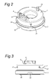
- Fig. 2 a perspective view of the force sensor assembly of Fig. 1 is shown when assembled, and Fig. 3 shows a side view of the same embodiment.
- Fig. 4 a cross sectional view is shown of this embodiment of the force sensor assembly 1.
- the force ring 2 of the force sensor assembly 1 is visible, as well as the sensor cap 7, connector 8 (with leaf spring connector elements 9, see also the cross sectional view of Fig. 4 ) and some orientation elements 21, 23 (to be discussed below).
- the force ring 2 is provided with an additional orientation element 22 in the form of a notch in the bottom and outer region of the force ring 2.
- the force attachment regions 24, 25 of the force ring 2 are indicated in these figures, e.g.
- the force sensor assembly 1 for use of the force sensor assembly 1 in an electromagnetic brake system, where the inner force attachment region 25 is e.g. in contact with the brake piston, and the outer force attachment region 24 is in contact with the brake caliper.
- the force attachment regions 24, 25 can be used over their entire circumferential surface, or it is possible to use a number of point force contact surfaces.
- Fig. 5 shows a perspective view of a force sensor assembly according to a second embodiment of the present invention
- Fig. 6 shows a side view of the force sensor assembly of Fig. 5
- This embodiment is provided with a connector 8 and connector springs 9 in the form of coil springs, which allow a connection to the connector in an axial direction, whereas the embodiment of Fig. 1-4 would also allow a connection in a tangential direction.
- the shape of the force ring 2 in this embodiment is different, providing a different force to signal behavior of the force sensor assembly 1.
- this second embodiment is provided with an orientation element 22 at the bottom side of the force ring 2 in the form of a local flattening of the force ring parallel to the measurement axis 14.
- the present invention embodiments relate to a force sensor assembly 1 having an axis of measurement along an axial direction 14 of the force sensor assembly 1.
- the force sensor assembly 1 comprises a force ring 2 provided with at least two sensing elements 3, a printed circuit board 4 having electronic components 5 thereon, a covering plate 6 for holding the printed circuit board 4 onto the force ring 2, and a sensor cap 7 covering the printed circuit board 4 and covering plate 6 and attached to the force ring 2.
- the covering plate 6 further accommodates an electrical connector 8, extending through a corresponding opening 8a in the sensor cap 7 when assembled (and through an opening 8b in the sealing member 12 when present).
- the electrical connector 8 e.g. comprises a housing element which provides space for holding a number of connector spring 9, which are held to the printed circuit board 4 under force.
- the connector springs 9 are leaf springs (visible in the cross sectional view of Fig. 4 ), allowing a mating connector to be connected in a tangential direction to the measurement axis 14, which in some applications provides additional ease of installation of the force sensor assembly.
- the connector springs 9 are coil springs which are held by the electrical connector 8 in force contact with the PCB 4 in the axial direction.
- the covering plate 6 provides for a number of functions in the force sensor assembly 1.
- the covering plate 6 comprises an internal metal clip 11, of which a two extending clips are visible in the exploded view of Fig. 1 .
- These extending clips can be attached to the force ring 2 (e.g. by contact welding) holding the PCB 4 and the covering plate 6 to the force ring, and possibly providing a case ground for the force sensor assembly 1.
- the force ring 2 is provided with assembly features allowing attachment of the extending clips 11 of the cover plate 6, e.g. against a rim of the force ring 2 (or alternatively in holes or grooves at the circumference of the force ring 2).
- the covering plate 6 may further comprise a plastic material, covering the internal metal clip 11 (entirely or partially), and which provides for an insulating covering of the PCB 4, but can also provide multiple orientation elements 20, 23 used in assembling the force sensor assembly 1.
- the covering plate 6 may be integrated with the sealing member 12, e.g. using a multi-compound molding technique.
- orientation elements 20 are provided on the top surface 15 of the covering plate 6, which co-operate with corresponding openings 20a in the sealing member 12.
- orientation elements 20 may be provided at the bottom surface of the covering plate 6, which co-operate with corresponding openings 20b in PCB 4 and notches 20c in the force ring 2.
- the orientation elements 20 on top and bottom surface of the covering plate may be positioned at different mutual positions.
- the covering plate 6 may be provided with an external orientation element 23, which protrudes through an opening 23 a in the sensor cap 7 (and a corresponding opening 23b in sealing member 12).
- the external orientation element 23 is provided roughly diametrically opposite the electrical connector 8, allowing a reliable and robust external attachment.
- the external orientation element 23 is positioned at a different position with respect to the connector 8.
- Fig. 7a shows a top view of a force ring 2 as useable in a force sensor assembly 1 according to a further embodiment of the present invention
- Fig. 7b shows a side view of the force ring 2 shown in Fig. 7a
- the measurement axis of the force sensor assembly 1 is indicated by 14 and extends perpendicular to the drawing surface of Fig. 7a .
- the at least two sensing elements 3 are evenly distributed on a circle on a top surface 15 of the force ring 2.
- the top surface 15 is sand blasted to provide a good attachment surface for the sensing elements 3, which are e.g. micro-fused silicon strain gauges (MSG).
- the at least two sensing elements 3 each have a sensitivity orientation (indicated by dashed lines 16) in a plane corresponding to a top surface 15 of the force ring 2, the sensitivity orientations 16 being directed at an angle to the center axis of the force sensor assembly 1 (indicated by 14 in Fig. 7a ). This allows a better access to the sensing elements 3 for wire bonding purposes during assembly of the force sensor assembly 1.
- the force ring 2 is provided with (symmetrically positioned) profiling features 17, e.g. in the form of indentations or grooves as shown in the embodiment of Fig. 7a .
- profiling features 17 will lower the tangential strain at the sensing elements 3 and make the force sensor assembly 1 more robust and reliable.
- the printed circuit board 4 and the covering plate 6 are provided with openings 18, 19. These openings 18, 19 are aligned with the positions of the at least two sensing element 3 on the force ring 2, allowing bonding of the contacts of the sensing elements 3 to corresponding bonding pads on the printed circuit board 4 after partial assembly of the force ring 2, printed circuit board 4 and covering plate 6.
- the at least two sensing elements 3 are covered with a protective material (e.g. a gel like material) in the voids provided by the openings 18, 19, in a further embodiment.
- a protective material e.g. a gel like material
- Fig. 8 shows a perspective view of a sensor cap 7 useable in an embodiment of the force sensor assembly 1 according to the present invention.
- An outer rim 30 and inner rim 31 are provided, which can be (laser) welded to the force ring 2 as shown in the Figs. 2, 3 , 5 , and 6 .
- the sensor cap 7 is provided with at least one orientation element 21, e.g. one or three dimples extending from the side of the sensor cap 7. These orientation elements can be advantageously used to aid in centering when installing the force sensor assembly 1.
- FIG. 9 an electrical circuit diagram is shown of (part of) the electronic components 5 and at least two sensing elements 3 used in a further embodiment of the force sensor assembly 1 according to the present invention.
- the at least two sensing elements 3 in this embodiment comprise four strain gauges (two impedances each) , which are arranged in a double parallel Wheatstone bridge configuration as indicated.
- the electrical circuit of the force sensor assembly 1 can then be externally connected.
- the signals V+ and V- are connected to processing circuitry, e.g. an ASIC, which is arranged to apply a temperature compensation gain and offset to the differential voltage and to provide an analogue force signal.
- each half Wheatstone bridge is connected to processing electronics (provided as electronic components 5 on the PCB 4), and each of these signals can be connected to an external unit (e.g. a controller unit for the electromagnetic brakes mentioned earlier).
- processing electronics provided as electronic components 5 on the PCB 4
- each of these signals can be connected to an external unit (e.g. a controller unit for the electromagnetic brakes mentioned earlier).
- an external unit e.g. a controller unit for the electromagnetic brakes mentioned earlier.
- suitable electronic components 5 to provide digital signal processing, and possibly a digital interface which can even be provided as a single wire output.
- Such a digital interfacing provides for more data signals over a single pin, and a more reliable connection than an analog signal output (e.g. allowing error detection and correction circuitry external to the force sensor assembly 1).
- Suitable interfacing is e.g. provided using SPI (Serial Peripheral Interface) or LIN (Local Interconnect Network) standards.
- a further aspect of the present invention relates to a method of manufacturing a force sensor assembly.
- the method comprises stacking a printed circuit board 4 having electronic components 5 thereon with a covering plate 6, fixing the printed circuit board 4 and the covering plate 6 on a force ring 2 provided with at least two sensing elements 3. This can be effected by attaching (e.g. welding) the covering plate 6 (e.g. using multiple extending pins of the internal metal clip 11) to the force ring 2. Subsequently, the at least two sensing elements 3 are electrically connected to the printed circuit board 4 (e.g. using wire bonds, through the openings 18, 19 provided in the covering plate 6 and PCB 4).
- an outer edge or outer rim 30 and an inner edge or inner rim 31 of the sensor cap 7 covering the printed circuit board 4 and covering plate 6 are welded to the force ring 2.
- the welding steps are e.g. implemented as laser welding, which is suitable for the orientations and spaces available in assembly of the force sensor assembly.
- this assembly only involves simple operations (only stacking, welding, bonding and welding of the sensor cap), the assembly can be implemented cost-effectively and reliable. Also the assembly steps involved will introduce only very moderate strain in the force ring 2, which can easily be accommodated for by using a calibration step after complete assembly.
- the present invention embodiments have been described above with reference to a number of exemplary embodiments as shown in the drawings. Modifications and alternative implementations of some parts or elements are possible, and are included in the scope of protection as defined in the appended claims.
Landscapes
- Engineering & Computer Science (AREA)
- Physics & Mathematics (AREA)
- General Physics & Mathematics (AREA)
- Transportation (AREA)
- Mechanical Engineering (AREA)
- Force Measurement Appropriate To Specific Purposes (AREA)
- Measurement Of Force In General (AREA)
Abstract
Description
- The present invention relates to a force sensor assembly having an axis of measurement along an axial direction of the force sensor assembly.
- German patent application
DE-A-103 50 085 discloses a measurement device for an electromagnetic brake. The measurement device comprises a closed ring member having a C-shaped profile, which deforms under a force being applied in the axial direction in a brake system. The C-shaped profile is provided with e.g. strain gauges that can measure the amount of deformation of the C-shaped profile (e.g. oriented in a radial direction). - UK patent application
GB-A-2 147 426 - The present invention seeks to provide a force sensor assembly, particularly suited for axial force measurement, which can be manufactured in an easy, reliable and cost-effective manner.
- According to the present invention, a force sensor assembly according to the preamble defined above is provided, comprising a force ring provided with at least two sensing elements, a printed circuit board having electronic components thereon, a covering plate for holding the printed circuit board onto the force ring, and a sensor cap covering the printed circuit board and covering plate and attached to the force ring.
- Such a force sensor assembly is easier to assemble than prior art force sensors, and also more cost-effective to manufacture. It can typically be applied in the automotive industry, more particular as a force sensor assembly in an electromagnetic brake system.
- According to a further aspect of the present invention, a method of assembling a force sensor assembly provided, comprising stacking a printed circuit board having electronic components with a covering plate, fixing the printed circuit board and the covering plate on a force ring provided with at least two sensing elements, by attaching the covering plate to the force ring, electrically connecting the at least two sensing elements to the printed circuit board, welding an outer rim and an inner rim of a sensor cap covering the printed circuit board and covering plate to the force ring.
- The present invention will be discussed in more detail below, using a number of exemplary embodiments, with reference to the attached drawings, in which
-
Fig. 1 shows an exploded view of a force sensor assembly according to a first embodiment of the present invention, wherein the main elements are shown separately; -
Fig. 2 shows a perspective view of the force sensor assembly ofFig. 1 when assembled; -
Fig. 3 shows a side view of the force sensor assembly ofFig. 2 ; -
Fig. 4 shows a cross sectional view of the force sensor assembly ofFig. 2 ; -
Fig. 5 shows a perspective view of a force sensor assembly according to a second embodiment of the present invention; -
Fig. 6 shows a side view of the force sensor assembly ofFig. 5 ; -
Fig. 7a shows a top view of a force ring as useable in a force sensor assembly according to a further embodiment of the present invention; -
Fig. 7b shows a side view of the force ring shown inFig. 7a ; -
Fig. 8 shows a perspective view of a sensor cap useable in an embodiment of the force sensor assembly according to the present invention; -
Fig. 9 shows an electrical circuit diagram of the electronic components used in a further embodiment of the force sensor assembly according to the present invention. - The present invention relates to a force sensor assembly, more specifically a force sensor assembly which can be used in automotive applications. The
force sensor assembly 1 is adapted to measure a force in axial direction, which is e.g. applied in measuring the force in an electromagnetic brake system (e.g. using a caliper). -
Fig. 1 shows an exploded view of a force sensor assembly according to a first embodiment of the present invention, wherein the main elements are shown separately. One of the main elements of theforce sensor assembly 1 is aforce ring 2, on which strain gages 3 (e.g. silicon strain gages such as micro-fused silicon strain gages (MSG)) are attached to measure a deformation of theforce ring 2. Theforce ring 2 may be a metal generally cylinder shaped body with anupper surface 15 perpendicular to itslongitudinal axis 14, wherein a force is applied on one direction on an outer region and in an opposite direction in an inner region, causing a deformation of theupper surface 15. Theforce ring 2 may be produced using metal injection molding techniques. - The other main elements of the
force sensor assembly 1 are a printed circuit board 4 (or equivalent holder) on whichelectronic components 5 are positioned (integrated circuits, and passive elements such as resistors, capacitors, etc.). Also acovering plate 6 is provided, which is used to fix thePCB 4 to theforce ring 2, and provides a number of functions which will be discussed below. Asensor cap 7 is provided for providing a cover of theforce sensor assembly 1 and for providing sufficient functional interfaces such as aconnector 8. Optionally a sealingmember 12 is provided which in co-operation with thesensor cap 7 ensures that the internal components of theforce sensor assembly 1 are not exposed to the environment. For this, the sealingmember 12 may be made of a compressible material. - In
Fig. 2 a perspective view of the force sensor assembly ofFig. 1 is shown when assembled, andFig. 3 shows a side view of the same embodiment. Furthermore, inFig. 4 a cross sectional view is shown of this embodiment of theforce sensor assembly 1. In assembled state, theforce ring 2 of theforce sensor assembly 1 is visible, as well as thesensor cap 7, connector 8 (with leafspring connector elements 9, see also the cross sectional view ofFig. 4 ) and someorientation elements 21, 23 (to be discussed below). Furthermore, in this embodiment, theforce ring 2 is provided with anadditional orientation element 22 in the form of a notch in the bottom and outer region of theforce ring 2. Furthermore, theforce attachment regions force ring 2 are indicated in these figures, e.g. for use of theforce sensor assembly 1 in an electromagnetic brake system, where the innerforce attachment region 25 is e.g. in contact with the brake piston, and the outerforce attachment region 24 is in contact with the brake caliper. Theforce attachment regions -
Fig. 5 shows a perspective view of a force sensor assembly according to a second embodiment of the present invention andFig. 6 shows a side view of the force sensor assembly ofFig. 5 . This embodiment is provided with aconnector 8 andconnector springs 9 in the form of coil springs, which allow a connection to the connector in an axial direction, whereas the embodiment ofFig. 1-4 would also allow a connection in a tangential direction. Furthermore, the shape of theforce ring 2 in this embodiment is different, providing a different force to signal behavior of theforce sensor assembly 1. Finally this second embodiment is provided with anorientation element 22 at the bottom side of theforce ring 2 in the form of a local flattening of the force ring parallel to themeasurement axis 14. - In general wording, the present invention embodiments relate to a
force sensor assembly 1 having an axis of measurement along anaxial direction 14 of theforce sensor assembly 1. Theforce sensor assembly 1 comprises aforce ring 2 provided with at least twosensing elements 3, aprinted circuit board 4 havingelectronic components 5 thereon, acovering plate 6 for holding the printedcircuit board 4 onto theforce ring 2, and asensor cap 7 covering the printedcircuit board 4 and coveringplate 6 and attached to theforce ring 2. - The
covering plate 6 further accommodates anelectrical connector 8, extending through acorresponding opening 8a in thesensor cap 7 when assembled (and through an opening 8b in thesealing member 12 when present). Theelectrical connector 8 e.g. comprises a housing element which provides space for holding a number ofconnector spring 9, which are held to the printedcircuit board 4 under force. In the embodiment ofFig. 1-4 , theconnector springs 9 are leaf springs (visible in the cross sectional view ofFig. 4 ), allowing a mating connector to be connected in a tangential direction to themeasurement axis 14, which in some applications provides additional ease of installation of the force sensor assembly. In the embodiment ofFig. 5-6 , theconnector springs 9 are coil springs which are held by theelectrical connector 8 in force contact with thePCB 4 in the axial direction. - The
covering plate 6 provides for a number of functions in theforce sensor assembly 1. In one embodiment, thecovering plate 6 comprises aninternal metal clip 11, of which a two extending clips are visible in the exploded view ofFig. 1 . These extending clips can be attached to the force ring 2 (e.g. by contact welding) holding thePCB 4 and thecovering plate 6 to the force ring, and possibly providing a case ground for theforce sensor assembly 1. As also shown in the cross sectional view ofFig. 4 , theforce ring 2 is provided with assembly features allowing attachment of the extendingclips 11 of thecover plate 6, e.g. against a rim of the force ring 2 (or alternatively in holes or grooves at the circumference of the force ring 2). - The
covering plate 6 may further comprise a plastic material, covering the internal metal clip 11 (entirely or partially), and which provides for an insulating covering of thePCB 4, but can also providemultiple orientation elements force sensor assembly 1. In a further embodiment, thecovering plate 6 may be integrated with the sealingmember 12, e.g. using a multi-compound molding technique. - As can be seen in the exploded view of
Fig. 1 ,orientation elements 20 are provided on thetop surface 15 of thecovering plate 6, which co-operate withcorresponding openings 20a in the sealingmember 12. At roughly the same position, alsoorientation elements 20 may be provided at the bottom surface of thecovering plate 6, which co-operate withcorresponding openings 20b inPCB 4 andnotches 20c in theforce ring 2. Of course, theorientation elements 20 on top and bottom surface of the covering plate may be positioned at different mutual positions. - Furthermore, the covering
plate 6 may be provided with anexternal orientation element 23, which protrudes through anopening 23 a in the sensor cap 7 (and acorresponding opening 23b in sealing member 12). In the embodiments shown, theexternal orientation element 23 is provided roughly diametrically opposite theelectrical connector 8, allowing a reliable and robust external attachment. In alternative embodiments, theexternal orientation element 23 is positioned at a different position with respect to theconnector 8. -
Fig. 7a shows a top view of aforce ring 2 as useable in aforce sensor assembly 1 according to a further embodiment of the present invention, andFig. 7b shows a side view of theforce ring 2 shown inFig. 7a . The measurement axis of theforce sensor assembly 1 is indicated by 14 and extends perpendicular to the drawing surface ofFig. 7a . - In general, to be able to measure the distortion of the
force ring 2 under axial loading, the at least twosensing elements 3 are evenly distributed on a circle on atop surface 15 of theforce ring 2. In an embodiment, thetop surface 15 is sand blasted to provide a good attachment surface for thesensing elements 3, which are e.g. micro-fused silicon strain gauges (MSG). - In a further embodiment, the at least two sensing elements 3 (e.g. four
elements 3 as shown in the embodiment ofFig. 7a and 7b ) each have a sensitivity orientation (indicated by dashed lines 16) in a plane corresponding to atop surface 15 of theforce ring 2, the sensitivity orientations 16 being directed at an angle to the center axis of the force sensor assembly 1 (indicated by 14 inFig. 7a ). This allows a better access to thesensing elements 3 for wire bonding purposes during assembly of theforce sensor assembly 1. - In yet a further embodiment, the
force ring 2 is provided with (symmetrically positioned) profiling features 17, e.g. in the form of indentations or grooves as shown in the embodiment ofFig. 7a . These profiling features 17 will lower the tangential strain at thesensing elements 3 and make theforce sensor assembly 1 more robust and reliable. - As shown most clearly in the exploded view of
Fig. 1 , the printedcircuit board 4 and thecovering plate 6 are provided withopenings openings sensing element 3 on theforce ring 2, allowing bonding of the contacts of thesensing elements 3 to corresponding bonding pads on the printedcircuit board 4 after partial assembly of theforce ring 2, printedcircuit board 4 and coveringplate 6. After this electrical connection of thesensing elements 3 to theelectronic components 5 on thePCB 4, the at least twosensing elements 3 are covered with a protective material (e.g. a gel like material) in the voids provided by theopenings -
Fig. 8 shows a perspective view of asensor cap 7 useable in an embodiment of theforce sensor assembly 1 according to the present invention. Anouter rim 30 andinner rim 31 are provided, which can be (laser) welded to theforce ring 2 as shown in theFigs. 2, 3 ,5 , and6 . Furthermore, thesensor cap 7 is provided with at least oneorientation element 21, e.g. one or three dimples extending from the side of thesensor cap 7. These orientation elements can be advantageously used to aid in centering when installing theforce sensor assembly 1. - In
Fig. 9 , an electrical circuit diagram is shown of (part of) theelectronic components 5 and at least twosensing elements 3 used in a further embodiment of theforce sensor assembly 1 according to the present invention. The at least twosensing elements 3 in this embodiment comprise four strain gauges (two impedances each) , which are arranged in a double parallel Wheatstone bridge configuration as indicated. The electrical circuit of theforce sensor assembly 1 can then be externally connected. The signals V+ and V- are connected to processing circuitry, e.g. an ASIC, which is arranged to apply a temperature compensation gain and offset to the differential voltage and to provide an analogue force signal. Then, using connector 8) with only three wires (analogue force signal , supply voltage Vs, and signal ground) the connection to the outside world can be made. In an alternative arrangement, each half Wheatstone bridge is connected to processing electronics (provided aselectronic components 5 on the PCB 4), and each of these signals can be connected to an external unit (e.g. a controller unit for the electromagnetic brakes mentioned earlier). This can be implemented using suitableelectronic components 5 to provide digital signal processing, and possibly a digital interface which can even be provided as a single wire output. Such a digital interfacing provides for more data signals over a single pin, and a more reliable connection than an analog signal output (e.g. allowing error detection and correction circuitry external to the force sensor assembly 1). Suitable interfacing is e.g. provided using SPI (Serial Peripheral Interface) or LIN (Local Interconnect Network) standards. - A further aspect of the present invention relates to a method of manufacturing a force sensor assembly. The method comprises stacking a printed
circuit board 4 havingelectronic components 5 thereon with acovering plate 6, fixing the printedcircuit board 4 and thecovering plate 6 on aforce ring 2 provided with at least twosensing elements 3. This can be effected by attaching (e.g. welding) the covering plate 6 (e.g. using multiple extending pins of the internal metal clip 11) to theforce ring 2. Subsequently, the at least twosensing elements 3 are electrically connected to the printed circuit board 4 (e.g. using wire bonds, through theopenings covering plate 6 and PCB 4). Finally, an outer edge orouter rim 30 and an inner edge orinner rim 31 of thesensor cap 7 covering the printedcircuit board 4 and coveringplate 6 are welded to theforce ring 2. The welding steps are e.g. implemented as laser welding, which is suitable for the orientations and spaces available in assembly of the force sensor assembly. As this assembly only involves simple operations (only stacking, welding, bonding and welding of the sensor cap), the assembly can be implemented cost-effectively and reliable. Also the assembly steps involved will introduce only very moderate strain in theforce ring 2, which can easily be accommodated for by using a calibration step after complete assembly. The present invention embodiments have been described above with reference to a number of exemplary embodiments as shown in the drawings. Modifications and alternative implementations of some parts or elements are possible, and are included in the scope of protection as defined in the appended claims.
Claims (15)
- Force sensor assembly having an axis of measurement along an axial direction (14) of the force sensor assembly (1), comprising
a force ring (2) provided with at least two sensing elements (3),
a printed circuit board (4) having electronic components (5) thereon,
a covering plate (6) for holding the printed circuit board (4) onto the force ring (2),
a sensor cap (7) covering the printed circuit board (4) and covering plate (6) and attached to the force ring (2). - Force sensor assembly according to claim 1, the covering plate (6) further accommodating an electrical connector (8) extending through the sensor cap (7).
- Force sensor assembly according to claim 1 or 2, the covering plate (6) comprising an internal metal clip (11).
- Force sensor assembly according to any one of claims 1-3, the covering plate (6) comprising plastic material.
- Force sensor assembly according to any one of claims 1-4, further comprising a sealing member (12) of compressible material between the covering plate (6) and the sensor cap (7).
- Force sensor assembly according to any one of claims 1-5, wherein the at least two sensing elements (3) are evenly distributed on a circle on a top surface (15) of the force ring (2).
- Force sensor assembly according to any one of claims 1-6, wherein the at least two sensing elements (3) comprise four strain gauges, which are arranged in a double parallel Wheatstone bridge configuration.
- Force sensor assembly according to any one of claims 1-7, wherein the at least two sensing elements (3) each have a sensitivity orientation (16) in a plane corresponding to a top surface (15) of the force ring (2), the sensitivity orientations 16) being directed at an angle to the center axis (14) of the force sensor assembly (1).
- Force sensor assembly according to any one of claims 1-8, wherein the force ring (2) is provided with profiling features (17).
- Force sensor assembly according to any one of claims 1-9, the printed circuit board (4) and the covering plate (7) being provided with openings (18, 19).
- Force sensor assembly according to any one of claims 1-10, wherein the at least two sensing elements (3) are covered with a protective material in the openings (18, 19).
- Force sensor assembly according to any one of claims 1-11, wherein the covering plate (6) is provided with orientation elements (20).
- Force sensor assembly according to any one of claims 1-12, wherein the force ring (2) is provided with assembly features allowing attachment of the cover plate (6).
- Force sensor assembly according to any one of claims 1-13, wherein the sensor cap (7) is provided with at least one orientation element (21).
- Method of assembling a force sensor assembly, comprising stacking a printed circuit board (4) having electronic components (5) with a covering plate (6),
fixing the printed circuit board (4) and the covering plate (6) on a force ring (2) provided with at least two sensing elements (3), by attaching the covering plate (6) to the force ring (2),
electrically connecting the at least two sensing elements (3) to the printed circuit board (4),
welding an outer rim and an inner rim of a sensor cap (7) covering the printed circuit board (4) and covering plate (6) to the force ring (2).
Priority Applications (5)
| Application Number | Priority Date | Filing Date | Title |
|---|---|---|---|
| EP11173545.2A EP2546625B1 (en) | 2011-07-12 | 2011-07-12 | Force sensor assembly and method for assembling a force sensor assembly |
| US13/531,970 US8733182B2 (en) | 2011-07-12 | 2012-06-25 | Force sensor assembly and method for assembling a force sensor assembly |
| JP2012148157A JP6059894B2 (en) | 2011-07-12 | 2012-07-02 | Force sensor assembly and method of assembling force sensor assembly |
| CN201210286976.0A CN102879131B (en) | 2011-07-12 | 2012-07-12 | Force sensor module and the method for assembly force sensor cluster |
| KR1020120075950A KR101846560B1 (en) | 2011-07-12 | 2012-07-12 | Force sensor assembly and method for assembling a force sensor assembly |
Applications Claiming Priority (1)
| Application Number | Priority Date | Filing Date | Title |
|---|---|---|---|
| EP11173545.2A EP2546625B1 (en) | 2011-07-12 | 2011-07-12 | Force sensor assembly and method for assembling a force sensor assembly |
Publications (2)
| Publication Number | Publication Date |
|---|---|
| EP2546625A1 true EP2546625A1 (en) | 2013-01-16 |
| EP2546625B1 EP2546625B1 (en) | 2016-04-13 |
Family
ID=45470139
Family Applications (1)
| Application Number | Title | Priority Date | Filing Date |
|---|---|---|---|
| EP11173545.2A Active EP2546625B1 (en) | 2011-07-12 | 2011-07-12 | Force sensor assembly and method for assembling a force sensor assembly |
Country Status (5)
| Country | Link |
|---|---|
| US (1) | US8733182B2 (en) |
| EP (1) | EP2546625B1 (en) |
| JP (1) | JP6059894B2 (en) |
| KR (1) | KR101846560B1 (en) |
| CN (1) | CN102879131B (en) |
Cited By (4)
| Publication number | Priority date | Publication date | Assignee | Title |
|---|---|---|---|---|
| EP3220116A1 (en) * | 2016-03-18 | 2017-09-20 | First Sensor Mobility GmbH | Force sensor device |
| EP3318212A1 (en) * | 2016-11-08 | 2018-05-09 | Covidien LP | Force sensors for surgical devices to prevent ingress of fluids |
| WO2021155046A1 (en) * | 2020-01-29 | 2021-08-05 | Sensata Technologies Inc. | Sensor apparatuses |
| US11454555B2 (en) | 2020-01-16 | 2022-09-27 | Sensata Technologies, Inc. | Force sensor apparatus and a method of assembling the same |
Families Citing this family (32)
| Publication number | Priority date | Publication date | Assignee | Title |
|---|---|---|---|---|
| JP6413652B2 (en) | 2013-11-05 | 2018-10-31 | 日本精工株式会社 | Force sensor |
| US9874490B2 (en) * | 2015-06-04 | 2018-01-23 | Ford Global Technologies, Llc | Method and system for detecting fluid leak via a strain gauge |
| CN106482815A (en) * | 2015-08-31 | 2017-03-08 | 泉州市王宫电子衡器有限公司 | Pick gold dual mode transducer |
| DE102015219569B4 (en) * | 2015-10-09 | 2024-05-16 | Vitesco Technologies Germany Gmbh | Electronic assembly, combination and method for assembling an electronic assembly |
| US10239213B1 (en) * | 2015-11-24 | 2019-03-26 | X Development Llc | Flexure assembly for force/torque sensing |
| DE102017211741B4 (en) | 2016-09-21 | 2024-11-07 | Continental Automotive Technologies GmbH | force sensor |
| KR101838188B1 (en) * | 2016-10-31 | 2018-03-13 | 비앤알(주) | Circular Stapler |
| JP6342971B2 (en) * | 2016-11-14 | 2018-06-13 | ファナック株式会社 | Force detection device and robot |
| US10094726B2 (en) * | 2017-02-01 | 2018-10-09 | Honeywell International Inc. | Membrane isolated, gel-filled force sensor |
| JP6746517B2 (en) * | 2017-03-08 | 2020-08-26 | 日本電産コパル電子株式会社 | Force sensor |
| JP6789853B2 (en) * | 2017-03-08 | 2020-11-25 | 日本電産コパル電子株式会社 | Force sensor |
| WO2019140148A1 (en) * | 2018-01-12 | 2019-07-18 | University Of Pittsburgh-Of The Commonwealth System Of Higher Education | Axial load cell |
| KR102047171B1 (en) | 2018-01-31 | 2019-11-20 | 한국식품연구원 | Kimchi Inoculating system and process thereof |
| US10744981B2 (en) * | 2018-06-06 | 2020-08-18 | Sensata Technologies, Inc. | Electromechanical braking connector |
| KR102595717B1 (en) * | 2018-11-01 | 2023-10-31 | 외티커 엔와이, 인크. | connection verifier |
| EP3671141B1 (en) * | 2018-12-20 | 2022-08-03 | Bizerba SE & Co. KG | Load cell and weighing foot |
| NO20211056A1 (en) | 2019-06-30 | 2021-09-03 | Halliburton Energy Services Inc | Integrated collar sensor for measuring mechanical impedance of the downhole tool |
| NO20211054A1 (en) | 2019-06-30 | 2021-09-03 | Halliburton Energy Services Inc | Integrated collar sensor for measuring performance characteristics of a drill motor |
| WO2021002832A1 (en) | 2019-06-30 | 2021-01-07 | Halliburton Energy Services, Inc. | Integrated collar sensor for measuring health of a downhole tool |
| NO20211055A1 (en) | 2019-06-30 | 2021-09-03 | Halliburton Energy Services Inc | Integrated collar sensor for a downhole tool |
| EP3795969A1 (en) * | 2019-09-18 | 2021-03-24 | Von Tringelberg UG | Force gauge |
| KR20240165930A (en) | 2022-03-17 | 2024-11-25 | 센사타 테크놀로지스, 인크 | Brake pedal with force sensor and membranes |
| DE102022203771A1 (en) | 2022-04-14 | 2023-10-19 | Continental Automotive Technologies GmbH | Measuring device and measuring method |
| CN117053958B (en) * | 2022-05-06 | 2026-07-17 | 精量电子(深圳)有限公司 | Force sensor |
| WO2023220369A1 (en) * | 2022-05-13 | 2023-11-16 | Sensata Technologies Inc. | Segmented interfaces to minimize impact of parasitic forces for strain measurement-based sensor |
| CN114623967B (en) * | 2022-05-17 | 2022-07-29 | 哈尔滨船舶锅炉涡轮机研究所(中国船舶集团有限公司第七0三研究所) | Preparation method of axial force measuring ring |
| CN115773833A (en) * | 2022-12-09 | 2023-03-10 | 武汉飞恩微电子有限公司 | a force sensor |
| CN115931188A (en) * | 2022-12-09 | 2023-04-07 | 武汉飞恩微电子有限公司 | a force sensor |
| CN116576997A (en) * | 2023-03-03 | 2023-08-11 | 武汉飞恩微电子有限公司 | A shaft force sensor |
| CN116858408A (en) * | 2023-03-03 | 2023-10-10 | 武汉飞恩微电子有限公司 | Shaft force sensor |
| CN116577003A (en) * | 2023-03-03 | 2023-08-11 | 武汉飞恩微电子有限公司 | Shaft force sensor |
| CN116576998A (en) * | 2023-03-03 | 2023-08-11 | 武汉飞恩微电子有限公司 | A shaft force sensor |
Citations (5)
| Publication number | Priority date | Publication date | Assignee | Title |
|---|---|---|---|---|
| GB2147426A (en) | 1983-09-30 | 1985-05-09 | Nat Res Dev | Load-measuring devices |
| US5490427A (en) * | 1994-10-17 | 1996-02-13 | Fanuc Usa Corporation | Six axis force sensor employing multiple shear strain gages |
| US6487911B1 (en) * | 2000-11-21 | 2002-12-03 | Texas Instruments Incorporated | Pressure sensor apparatus |
| DE10350085A1 (en) | 2003-10-27 | 2005-06-02 | Siemens Ag | Measurement instrument e.g. for electro mechanical brake, has force sensor in form of closed ring, having profile with two C-shaped in cross section and introduction of force on instrument on sensor takes place on edge of closed ring |
| WO2008067392A2 (en) * | 2006-11-28 | 2008-06-05 | The Timken Company | Load sensor and method of sensing a load |
Family Cites Families (21)
| Publication number | Priority date | Publication date | Assignee | Title |
|---|---|---|---|---|
| WO1986003115A1 (en) * | 1984-11-30 | 1986-06-05 | Graeme John Clare | Tocodynamometers |
| JPH0543041U (en) * | 1991-11-15 | 1993-06-11 | エヌオーケー株式会社 | Axial force sensor |
| JP3265488B2 (en) * | 1993-01-13 | 2002-03-11 | ニッタ株式会社 | Manufacturing method of force / moment detecting device |
| US6272927B1 (en) * | 1999-10-20 | 2001-08-14 | Texas Instruments Incorporated | Hermetically sealed pressure sensing device |
| DE10231727A1 (en) * | 2002-07-13 | 2004-01-22 | Robert Bosch Gmbh | Micromechanical pressure sensor device and corresponding measuring arrangement |
| US6742395B1 (en) * | 2002-12-20 | 2004-06-01 | Texas Instruments Incorporated | Hermetic pressure transducer |
| US7570065B2 (en) * | 2006-03-01 | 2009-08-04 | Loadstar Sensors Inc | Cylindrical capacitive force sensing device and method |
| JP4774678B2 (en) * | 2003-08-29 | 2011-09-14 | 富士電機株式会社 | Pressure sensor device |
| US7047823B2 (en) * | 2004-06-23 | 2006-05-23 | Texas Instruments Incorporated | Apparatus for mounting electronic module assembly in sensor |
| US7000478B1 (en) * | 2005-01-31 | 2006-02-21 | Texas Instruments Incorporated | Combined pressure and temperature transducer |
| JP4605525B2 (en) * | 2005-04-15 | 2011-01-05 | 璋好 小林 | Force transducer |
| JP4997801B2 (en) * | 2006-03-20 | 2012-08-08 | 日産自動車株式会社 | Suspension body input load measuring device |
| US20100052578A1 (en) * | 2006-11-15 | 2010-03-04 | J&J Corp. | Subminiature linear vibrator |
| US7383737B1 (en) * | 2007-03-29 | 2008-06-10 | Delphi Technologies, Inc | Capacitive pressure sensor |
| JP5008188B2 (en) * | 2007-05-31 | 2012-08-22 | ミネベア株式会社 | Triaxial force sensor and triaxial force detection method |
| CN201138258Y (en) * | 2008-01-07 | 2008-10-22 | 南京高华科技有限公司 | Surface mounted combined pressure sensor |
| US8287204B2 (en) * | 2008-06-23 | 2012-10-16 | Silverbrook Research Pty Ltd | Electronic pen with retractable and replaceable cartridge |
| JP5339846B2 (en) * | 2008-10-21 | 2013-11-13 | 大和製衡株式会社 | Load cell and weight measuring device |
| CN101598613A (en) * | 2009-04-24 | 2009-12-09 | 中国科学院合肥物质科学研究院 | Miniature five-dimensional force sensor with overload protection and its force vector information acquisition method |
| CN101832830B (en) * | 2010-03-22 | 2011-07-20 | 西安交通大学 | Flush packaged pressure sensor with high temperature resistance and high frequency response |
| US8156816B2 (en) * | 2010-05-27 | 2012-04-17 | Sensata Technologies, Inc. | Pressure sensor |
-
2011
- 2011-07-12 EP EP11173545.2A patent/EP2546625B1/en active Active
-
2012
- 2012-06-25 US US13/531,970 patent/US8733182B2/en active Active - Reinstated
- 2012-07-02 JP JP2012148157A patent/JP6059894B2/en active Active
- 2012-07-12 KR KR1020120075950A patent/KR101846560B1/en active Active
- 2012-07-12 CN CN201210286976.0A patent/CN102879131B/en active Active
Patent Citations (5)
| Publication number | Priority date | Publication date | Assignee | Title |
|---|---|---|---|---|
| GB2147426A (en) | 1983-09-30 | 1985-05-09 | Nat Res Dev | Load-measuring devices |
| US5490427A (en) * | 1994-10-17 | 1996-02-13 | Fanuc Usa Corporation | Six axis force sensor employing multiple shear strain gages |
| US6487911B1 (en) * | 2000-11-21 | 2002-12-03 | Texas Instruments Incorporated | Pressure sensor apparatus |
| DE10350085A1 (en) | 2003-10-27 | 2005-06-02 | Siemens Ag | Measurement instrument e.g. for electro mechanical brake, has force sensor in form of closed ring, having profile with two C-shaped in cross section and introduction of force on instrument on sensor takes place on edge of closed ring |
| WO2008067392A2 (en) * | 2006-11-28 | 2008-06-05 | The Timken Company | Load sensor and method of sensing a load |
Cited By (8)
| Publication number | Priority date | Publication date | Assignee | Title |
|---|---|---|---|---|
| EP3220116A1 (en) * | 2016-03-18 | 2017-09-20 | First Sensor Mobility GmbH | Force sensor device |
| US10041845B2 (en) | 2016-03-18 | 2018-08-07 | First Sensor Mobility Gmbh | Force sensor device |
| EP3318212A1 (en) * | 2016-11-08 | 2018-05-09 | Covidien LP | Force sensors for surgical devices to prevent ingress of fluids |
| EP3656333A1 (en) * | 2016-11-08 | 2020-05-27 | Covidien LP | Force sensors for surgical devices to prevent ingress of fluids |
| US11454555B2 (en) | 2020-01-16 | 2022-09-27 | Sensata Technologies, Inc. | Force sensor apparatus and a method of assembling the same |
| WO2021155046A1 (en) * | 2020-01-29 | 2021-08-05 | Sensata Technologies Inc. | Sensor apparatuses |
| US20230085965A1 (en) * | 2020-01-29 | 2023-03-23 | Sensata Technologies, Inc. | Sensor apparatuses |
| US12298195B2 (en) * | 2020-01-29 | 2025-05-13 | Sensata Technologies, Inc. | Sensor apparatuses |
Also Published As
| Publication number | Publication date |
|---|---|
| JP6059894B2 (en) | 2017-01-11 |
| KR101846560B1 (en) | 2018-04-06 |
| CN102879131A (en) | 2013-01-16 |
| US8733182B2 (en) | 2014-05-27 |
| US20130014595A1 (en) | 2013-01-17 |
| KR20130008483A (en) | 2013-01-22 |
| CN102879131B (en) | 2016-09-14 |
| JP2013019895A (en) | 2013-01-31 |
| EP2546625B1 (en) | 2016-04-13 |
Similar Documents
| Publication | Publication Date | Title |
|---|---|---|
| EP2546625B1 (en) | Force sensor assembly and method for assembling a force sensor assembly | |
| EP1686363A1 (en) | Combined pressure and temperature transducer | |
| JP6301230B2 (en) | Physical quantity measuring device | |
| CN104697699B (en) | Physical Quantity Measurement Sensor and Sensor Module | |
| KR20150083029A (en) | Sensor for detecting a temperature and a pressure of a fluid medium | |
| EP4078124B1 (en) | Force sensor apparatus and a method of assembling the same | |
| KR102012986B1 (en) | A measuring plug and method for assembling a measuring plug | |
| CN103033231A (en) | Joint between a pressure sensor and a pressure port of a sensor assembly | |
| CN117073873A (en) | Force sensor for electromechanical braking system and preparation method | |
| US20250044171A1 (en) | Force sensor apparatus for electromechanical brake | |
| EP3273213B1 (en) | Low cost overmolded leadframe force sensor with multiple mounting positions | |
| CN107250751B (en) | Hydraulic sensors, hydraulic control units and components, and vehicle braking systems | |
| CN103728093A (en) | Pressure sensor with robustness against mounting stress | |
| HK40020929A (en) | Physical quantity measuring sensor and sensor module | |
| JP5997686B2 (en) | Physical quantity measurement sensor | |
| JP2015111067A (en) | Sensor module and physical quantity sensor |
Legal Events
| Date | Code | Title | Description |
|---|---|---|---|
| PUAI | Public reference made under article 153(3) epc to a published international application that has entered the european phase |
Free format text: ORIGINAL CODE: 0009012 |
|
| AK | Designated contracting states |
Kind code of ref document: A1 Designated state(s): AL AT BE BG CH CY CZ DE DK EE ES FI FR GB GR HR HU IE IS IT LI LT LU LV MC MK MT NL NO PL PT RO RS SE SI SK SM TR |
|
| AX | Request for extension of the european patent |
Extension state: BA ME |
|
| 17P | Request for examination filed |
Effective date: 20130507 |
|
| 17Q | First examination report despatched |
Effective date: 20130624 |
|
| GRAP | Despatch of communication of intention to grant a patent |
Free format text: ORIGINAL CODE: EPIDOSNIGR1 |
|
| INTG | Intention to grant announced |
Effective date: 20151022 |
|
| GRAS | Grant fee paid |
Free format text: ORIGINAL CODE: EPIDOSNIGR3 |
|
| GRAA | (expected) grant |
Free format text: ORIGINAL CODE: 0009210 |
|
| AK | Designated contracting states |
Kind code of ref document: B1 Designated state(s): AL AT BE BG CH CY CZ DE DK EE ES FI FR GB GR HR HU IE IS IT LI LT LU LV MC MK MT NL NO PL PT RO RS SE SI SK SM TR |
|
| REG | Reference to a national code |
Ref country code: GB Ref legal event code: FG4D |
|
| REG | Reference to a national code |
Ref country code: AT Ref legal event code: REF Ref document number: 790641 Country of ref document: AT Kind code of ref document: T Effective date: 20160415 Ref country code: CH Ref legal event code: EP |
|
| REG | Reference to a national code |
Ref country code: IE Ref legal event code: FG4D |
|
| REG | Reference to a national code |
Ref country code: DE Ref legal event code: R096 Ref document number: 602011025208 Country of ref document: DE |
|
| REG | Reference to a national code |
Ref country code: LT Ref legal event code: MG4D |
|
| REG | Reference to a national code |
Ref country code: AT Ref legal event code: MK05 Ref document number: 790641 Country of ref document: AT Kind code of ref document: T Effective date: 20160413 |
|
| REG | Reference to a national code |
Ref country code: NL Ref legal event code: MP Effective date: 20160413 |
|
| PG25 | Lapsed in a contracting state [announced via postgrant information from national office to epo] |
Ref country code: FI Free format text: LAPSE BECAUSE OF FAILURE TO SUBMIT A TRANSLATION OF THE DESCRIPTION OR TO PAY THE FEE WITHIN THE PRESCRIBED TIME-LIMIT Effective date: 20160413 Ref country code: NL Free format text: LAPSE BECAUSE OF FAILURE TO SUBMIT A TRANSLATION OF THE DESCRIPTION OR TO PAY THE FEE WITHIN THE PRESCRIBED TIME-LIMIT Effective date: 20160413 Ref country code: LT Free format text: LAPSE BECAUSE OF FAILURE TO SUBMIT A TRANSLATION OF THE DESCRIPTION OR TO PAY THE FEE WITHIN THE PRESCRIBED TIME-LIMIT Effective date: 20160413 Ref country code: PL Free format text: LAPSE BECAUSE OF FAILURE TO SUBMIT A TRANSLATION OF THE DESCRIPTION OR TO PAY THE FEE WITHIN THE PRESCRIBED TIME-LIMIT Effective date: 20160413 Ref country code: NO Free format text: LAPSE BECAUSE OF FAILURE TO SUBMIT A TRANSLATION OF THE DESCRIPTION OR TO PAY THE FEE WITHIN THE PRESCRIBED TIME-LIMIT Effective date: 20160713 |
|
| PG25 | Lapsed in a contracting state [announced via postgrant information from national office to epo] |
Ref country code: ES Free format text: LAPSE BECAUSE OF FAILURE TO SUBMIT A TRANSLATION OF THE DESCRIPTION OR TO PAY THE FEE WITHIN THE PRESCRIBED TIME-LIMIT Effective date: 20160413 Ref country code: GR Free format text: LAPSE BECAUSE OF FAILURE TO SUBMIT A TRANSLATION OF THE DESCRIPTION OR TO PAY THE FEE WITHIN THE PRESCRIBED TIME-LIMIT Effective date: 20160714 Ref country code: SE Free format text: LAPSE BECAUSE OF FAILURE TO SUBMIT A TRANSLATION OF THE DESCRIPTION OR TO PAY THE FEE WITHIN THE PRESCRIBED TIME-LIMIT Effective date: 20160413 Ref country code: RS Free format text: LAPSE BECAUSE OF FAILURE TO SUBMIT A TRANSLATION OF THE DESCRIPTION OR TO PAY THE FEE WITHIN THE PRESCRIBED TIME-LIMIT Effective date: 20160413 Ref country code: PT Free format text: LAPSE BECAUSE OF FAILURE TO SUBMIT A TRANSLATION OF THE DESCRIPTION OR TO PAY THE FEE WITHIN THE PRESCRIBED TIME-LIMIT Effective date: 20160816 Ref country code: HR Free format text: LAPSE BECAUSE OF FAILURE TO SUBMIT A TRANSLATION OF THE DESCRIPTION OR TO PAY THE FEE WITHIN THE PRESCRIBED TIME-LIMIT Effective date: 20160413 Ref country code: LV Free format text: LAPSE BECAUSE OF FAILURE TO SUBMIT A TRANSLATION OF THE DESCRIPTION OR TO PAY THE FEE WITHIN THE PRESCRIBED TIME-LIMIT Effective date: 20160413 Ref country code: AT Free format text: LAPSE BECAUSE OF FAILURE TO SUBMIT A TRANSLATION OF THE DESCRIPTION OR TO PAY THE FEE WITHIN THE PRESCRIBED TIME-LIMIT Effective date: 20160413 |
|
| PG25 | Lapsed in a contracting state [announced via postgrant information from national office to epo] |
Ref country code: IT Free format text: LAPSE BECAUSE OF FAILURE TO SUBMIT A TRANSLATION OF THE DESCRIPTION OR TO PAY THE FEE WITHIN THE PRESCRIBED TIME-LIMIT Effective date: 20160413 Ref country code: BE Free format text: LAPSE BECAUSE OF FAILURE TO SUBMIT A TRANSLATION OF THE DESCRIPTION OR TO PAY THE FEE WITHIN THE PRESCRIBED TIME-LIMIT Effective date: 20160413 |
|
| REG | Reference to a national code |
Ref country code: DE Ref legal event code: R097 Ref document number: 602011025208 Country of ref document: DE |
|
| PG25 | Lapsed in a contracting state [announced via postgrant information from national office to epo] |
Ref country code: RO Free format text: LAPSE BECAUSE OF FAILURE TO SUBMIT A TRANSLATION OF THE DESCRIPTION OR TO PAY THE FEE WITHIN THE PRESCRIBED TIME-LIMIT Effective date: 20160413 Ref country code: EE Free format text: LAPSE BECAUSE OF FAILURE TO SUBMIT A TRANSLATION OF THE DESCRIPTION OR TO PAY THE FEE WITHIN THE PRESCRIBED TIME-LIMIT Effective date: 20160413 Ref country code: SK Free format text: LAPSE BECAUSE OF FAILURE TO SUBMIT A TRANSLATION OF THE DESCRIPTION OR TO PAY THE FEE WITHIN THE PRESCRIBED TIME-LIMIT Effective date: 20160413 Ref country code: CZ Free format text: LAPSE BECAUSE OF FAILURE TO SUBMIT A TRANSLATION OF THE DESCRIPTION OR TO PAY THE FEE WITHIN THE PRESCRIBED TIME-LIMIT Effective date: 20160413 Ref country code: DK Free format text: LAPSE BECAUSE OF FAILURE TO SUBMIT A TRANSLATION OF THE DESCRIPTION OR TO PAY THE FEE WITHIN THE PRESCRIBED TIME-LIMIT Effective date: 20160413 |
|
| PLBE | No opposition filed within time limit |
Free format text: ORIGINAL CODE: 0009261 |
|
| STAA | Information on the status of an ep patent application or granted ep patent |
Free format text: STATUS: NO OPPOSITION FILED WITHIN TIME LIMIT |
|
| PG25 | Lapsed in a contracting state [announced via postgrant information from national office to epo] |
Ref country code: SM Free format text: LAPSE BECAUSE OF FAILURE TO SUBMIT A TRANSLATION OF THE DESCRIPTION OR TO PAY THE FEE WITHIN THE PRESCRIBED TIME-LIMIT Effective date: 20160413 |
|
| REG | Reference to a national code |
Ref country code: CH Ref legal event code: PL |
|
| 26N | No opposition filed |
Effective date: 20170116 |
|
| PG25 | Lapsed in a contracting state [announced via postgrant information from national office to epo] |
Ref country code: MC Free format text: LAPSE BECAUSE OF FAILURE TO SUBMIT A TRANSLATION OF THE DESCRIPTION OR TO PAY THE FEE WITHIN THE PRESCRIBED TIME-LIMIT Effective date: 20160413 |
|
| PG25 | Lapsed in a contracting state [announced via postgrant information from national office to epo] |
Ref country code: FR Free format text: LAPSE BECAUSE OF NON-PAYMENT OF DUE FEES Effective date: 20160801 Ref country code: LI Free format text: LAPSE BECAUSE OF NON-PAYMENT OF DUE FEES Effective date: 20160731 Ref country code: CH Free format text: LAPSE BECAUSE OF NON-PAYMENT OF DUE FEES Effective date: 20160731 |
|
| REG | Reference to a national code |
Ref country code: FR Ref legal event code: ST Effective date: 20170331 |
|
| REG | Reference to a national code |
Ref country code: IE Ref legal event code: MM4A |
|
| PG25 | Lapsed in a contracting state [announced via postgrant information from national office to epo] |
Ref country code: SI Free format text: LAPSE BECAUSE OF FAILURE TO SUBMIT A TRANSLATION OF THE DESCRIPTION OR TO PAY THE FEE WITHIN THE PRESCRIBED TIME-LIMIT Effective date: 20160413 |
|
| PG25 | Lapsed in a contracting state [announced via postgrant information from national office to epo] |
Ref country code: IE Free format text: LAPSE BECAUSE OF NON-PAYMENT OF DUE FEES Effective date: 20160712 |
|
| PG25 | Lapsed in a contracting state [announced via postgrant information from national office to epo] |
Ref country code: LU Free format text: LAPSE BECAUSE OF NON-PAYMENT OF DUE FEES Effective date: 20160712 |
|
| PG25 | Lapsed in a contracting state [announced via postgrant information from national office to epo] |
Ref country code: HU Free format text: LAPSE BECAUSE OF FAILURE TO SUBMIT A TRANSLATION OF THE DESCRIPTION OR TO PAY THE FEE WITHIN THE PRESCRIBED TIME-LIMIT; INVALID AB INITIO Effective date: 20110712 Ref country code: CY Free format text: LAPSE BECAUSE OF FAILURE TO SUBMIT A TRANSLATION OF THE DESCRIPTION OR TO PAY THE FEE WITHIN THE PRESCRIBED TIME-LIMIT Effective date: 20160413 |
|
| PG25 | Lapsed in a contracting state [announced via postgrant information from national office to epo] |
Ref country code: MT Free format text: LAPSE BECAUSE OF NON-PAYMENT OF DUE FEES Effective date: 20160731 Ref country code: IS Free format text: LAPSE BECAUSE OF FAILURE TO SUBMIT A TRANSLATION OF THE DESCRIPTION OR TO PAY THE FEE WITHIN THE PRESCRIBED TIME-LIMIT Effective date: 20160413 Ref country code: MK Free format text: LAPSE BECAUSE OF FAILURE TO SUBMIT A TRANSLATION OF THE DESCRIPTION OR TO PAY THE FEE WITHIN THE PRESCRIBED TIME-LIMIT Effective date: 20160413 Ref country code: TR Free format text: LAPSE BECAUSE OF FAILURE TO SUBMIT A TRANSLATION OF THE DESCRIPTION OR TO PAY THE FEE WITHIN THE PRESCRIBED TIME-LIMIT Effective date: 20160413 |
|
| PG25 | Lapsed in a contracting state [announced via postgrant information from national office to epo] |
Ref country code: BG Free format text: LAPSE BECAUSE OF FAILURE TO SUBMIT A TRANSLATION OF THE DESCRIPTION OR TO PAY THE FEE WITHIN THE PRESCRIBED TIME-LIMIT Effective date: 20160413 |
|
| PG25 | Lapsed in a contracting state [announced via postgrant information from national office to epo] |
Ref country code: AL Free format text: LAPSE BECAUSE OF FAILURE TO SUBMIT A TRANSLATION OF THE DESCRIPTION OR TO PAY THE FEE WITHIN THE PRESCRIBED TIME-LIMIT Effective date: 20160413 |
|
| REG | Reference to a national code |
Ref country code: DE Ref legal event code: R082 Ref document number: 602011025208 Country of ref document: DE Representative=s name: KILBURN & STRODE LLP, NL |
|
| P01 | Opt-out of the competence of the unified patent court (upc) registered |
Effective date: 20230708 |
|
| PGFP | Annual fee paid to national office [announced via postgrant information from national office to epo] |
Ref country code: DE Payment date: 20250729 Year of fee payment: 15 |
|
| PGFP | Annual fee paid to national office [announced via postgrant information from national office to epo] |
Ref country code: GB Payment date: 20250728 Year of fee payment: 15 |