EP2546619A1 - Method for measuring and calculating vibrations of a blade in an axial turbo engine - Google Patents
Method for measuring and calculating vibrations of a blade in an axial turbo engine Download PDFInfo
- Publication number
- EP2546619A1 EP2546619A1 EP11174143A EP11174143A EP2546619A1 EP 2546619 A1 EP2546619 A1 EP 2546619A1 EP 11174143 A EP11174143 A EP 11174143A EP 11174143 A EP11174143 A EP 11174143A EP 2546619 A1 EP2546619 A1 EP 2546619A1
- Authority
- EP
- European Patent Office
- Prior art keywords
- blade
- measuring
- modal
- field
- quantities
- Prior art date
- Legal status (The legal status is an assumption and is not a legal conclusion. Google has not performed a legal analysis and makes no representation as to the accuracy of the status listed.)
- Withdrawn
Links
Images
Classifications
-
- F—MECHANICAL ENGINEERING; LIGHTING; HEATING; WEAPONS; BLASTING
- F01—MACHINES OR ENGINES IN GENERAL; ENGINE PLANTS IN GENERAL; STEAM ENGINES
- F01D—NON-POSITIVE DISPLACEMENT MACHINES OR ENGINES, e.g. STEAM TURBINES
- F01D5/00—Blades; Blade-carrying members; Heating, heat-insulating, cooling or antivibration means on the blades or the members
- F01D5/12—Blades
- F01D5/14—Form or construction
- F01D5/16—Form or construction for counteracting blade vibration
-
- G—PHYSICS
- G01—MEASURING; TESTING
- G01H—MEASUREMENT OF MECHANICAL VIBRATIONS OR ULTRASONIC, SONIC OR INFRASONIC WAVES
- G01H1/00—Measuring characteristics of vibrations in solids by using direct conduction to the detector
- G01H1/003—Measuring characteristics of vibrations in solids by using direct conduction to the detector of rotating machines
- G01H1/006—Measuring characteristics of vibrations in solids by using direct conduction to the detector of rotating machines of the rotor of turbo machines
-
- G—PHYSICS
- G01—MEASURING; TESTING
- G01M—TESTING STATIC OR DYNAMIC BALANCE OF MACHINES OR STRUCTURES; TESTING OF STRUCTURES OR APPARATUS, NOT OTHERWISE PROVIDED FOR
- G01M7/00—Vibration-testing of structures; Shock-testing of structures
- G01M7/02—Vibration-testing by means of a shake table
- G01M7/025—Measuring arrangements
Definitions
- the invention relates to a method for measuring vibrations of a blade in an axial turbomachine.
- An axial turbomachine includes a compressor and a turbine. Buckets are used both in the compressor and in the turbine; a distinction is made between fixed guide vanes and rotating rotor blades. The blades are firmly clamped in wheels and can swing, with a fixed end at the blade root and a loose end at the blade tip. As a result, a vibration always has a vibration node on the blade root.
- oscillation processes may occur in which oscillation states occur with high and critical stresses in the blade. Long-term loading of the blade by critical stress conditions leads to material fatigue, which can ultimately lead to a lifetime reduction of the blade, which necessitates replacement of the blade.
- it is necessary to measure the vibrations so that loads can be kept short in time by suitably setting the operating state.
- the vibrations of the blade are measured at measuring points on the blade tip, the measurements being carried out with an optical measuring method or by means of radar.
- no information about the vibration condition in the area below the blade tip is obtained, in particular no information is obtained about whether next to the blade tip Vibration node on the blade root further nodes are present, it is therefore no statement about the vibration mode possible.
- a knowledge of the vibration state of the blade over the entire blade height is required, in particular a knowledge of the vibration state at the blade root is required.
- the object of the invention is to provide a measuring method for measuring vibrations of the blade during operation of the axial turbomachine, the measuring method providing information about the vibration state of the entire blade and information about mechanical vibration loads of the blade.
- the inventive method for measuring vibrations of a blade in an axial turbomachine comprises the steps of: calculating modal field quantities for a plurality of vibration modes of the blade; Determining at least two measurement locations on the airfoil surface and measuring at least one measurement area size at each measurement location; Determining modal coordinates of the blade from the at least two field sizes and the modal field sizes at the points of measurement; Determine structural mechanics quantities at predetermined locations of the blade from the modal field sizes at the predetermined locations and the modal coordinates.
- a plurality of relevant vibration modes of the blade are calculated.
- the modal field sizes are calculated for each point of the blade.
- at least two measuring points on the blade surface are determined and at each of these measuring points at least one measuring field size is measured.
- the vibration of the blade can be represented as a linear combination of the vibration modes.
- the coefficients of the linear combination are obtained.
- the coefficients of the linear combination are collected in the modal coordinates.
- the modal coordinates are applied to the computationally determined modal field magnitudes in order to determine structure-mechanical variables at predetermined locations.
- the method according to the invention advantageously makes it possible to determine from which vibration modes the vibration of the blade is composed.
- the method according to the invention advantageously makes it possible to determine structural-mechanical variables at the predetermined points of the blade which are not identical with the measuring points.
- the modal field variables, the measurement field variables and the structural mechanical variables are preferably deflections, displacements, strains, speeds and / or stresses.
- the method according to the invention advantageously makes it possible to use the measuring field quantities, e.g. Speeds to compare with the calculated modal field sizes, in this case computationally determined speeds in order to determine the modal coordinates.
- structural-mechanical quantities can be determined at predetermined points of the blade.
- the structural mechanical quantities may advantageously be variables other than speeds, e.g. Voltages, provided that the other variables were determined mathematically in the first method step.
- the measurement field quantities are preferably measured relative to the rotation of the axial turbomachine. Furthermore, the measuring field quantities are measured using an optical measuring method, by means of radar and / or by means of electromagnetic sensors.
- the modal field quantities are preferably determined by calculation using a finite element method.
- the at least one predetermined location is preferably arranged on the blade root.
- the blade root is exposed to the vibration of the blade of a high load, in particular by high voltages.
- the method according to the invention is preferably carried out with the step of determining a temporal development of the structural mechanical variable at the at least one predetermined location by repeating the method steps.
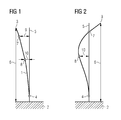
- a blade 1 is attached to a clamping 2 of a rotor of an axial turbomachine.
- the blade 1 has at the end facing away from the clamping 2 a blade tip 3.
- a fixed terminal 4 is arranged in the vicinity of the blade root (not shown), at which the clamping 2 facing the end of the blade 1, a fixed terminal 4 is arranged.
- a vertical line, which starts from the clamping 2, denotes the blade position at rest 5.
- the blade height 6 extends away from the clamping 2 to the blade tip 3.
- two measuring points 6, 7 are arranged at two different blade height levels, with an upper measuring point 6 and a lower measuring point 7, wherein both measuring points 6, 7 between the blade tip 3 and the fixed terminal 4 are arranged.
- the distance between the upper measuring point 7 and the blade position at rest 5 is the deflection of the upper measuring point 9
- the distance between the lower measuring point 8 and the blade position in the resting state 5 is the deflection of the lower measuring point
- Figures 1 and 2 has vibration states with blade layers, which of the blade position at rest 5 are different. Both vibration states each have a vibration node at the fixed terminal 4.
- the vibration state of the blade in Fig. 1 has only one vibration node, namely at the fixed end 4.
- the maximum deflection occurs at the blade tip 3.
- the vibrational state in Fig. 2 has two vibration nodes, wherein a second vibration node at the upper measuring point 7 occurs next to the vibration node at the fixed end point 4.
- the maximum deflection occurs between upper measuring point 9 and lower measuring point 10.
- a finite element method is used to calculate different vibration modes, namely vibration modes with one, two and three vibration nodes in the radial direction, as well as vibration modes with one and two vibration nodes in the circumferential direction. Velocities, displacements and stresses are calculated for each of the vibration modes and for each point of the blade.
- There are ten measuring points for measuring a speed on the blade surface arranged such that an identification of the vibration modes is possible by comparing the computationally determined modal field sizes at the measuring points and the measuring field sizes.
- the speeds at the measuring points are measured for each measuring point, for example by means of radar relative to the rotation of the axial turbomachine.
- the speeds measured in this way are expressed by a linear combination of the computationally determined speeds of the different vibration modes at the measuring points.
- the coefficients of the linear combination are collected in the modal coordinates.
- the modal coordinates are applied to the calculated stresses and the stresses on the blade root are determined. By repeating the process steps, the time evolution of the stresses on the blade root is determined.
Abstract
Description
Die Erfindung betrifft ein Verfahren zum Messen von Schwingungen einer Schaufel in einer Axialturbomaschine.The invention relates to a method for measuring vibrations of a blade in an axial turbomachine.
Eine Axialturbomaschine weist einen Verdichter und eine Turbine auf. Sowohl im Verdichter als auch in der Turbine kommen Schaufeln zum Einsatz, unterschieden werden dabei fest stehende Leitschaufeln und rotierende Laufschaufeln. Die Laufschaufeln sind dabei in Laufrädern fest eingespannt und können schwingen, wobei am Schaufelfuß ein festes Ende und an der Schaufelspitze ein loses Ende vorliegt. Folgegemäß liegt bei einer Schwingung immer ein Schwingungsknoten am Schaufelfuß. In Abhängigkeit des Betriebszustands der Axialturbomaschine kann es dabei zu Schwingungsvorgängen kommen, bei denen Schwingungszustände mit hohen und kritischen Spannungen in der Schaufel auftreten. Bei einer langen zeitlichen Belastung der Schaufel durch kritische Spannungszustände kommt es zu einer Materialermüdung, die letztendlich zu einer Lebensdauerreduzierung der Schaufel führen kann, welche einen Austausch der Schaufel notwendig macht. Zur Überwachung der kritischen Spannungszustände ist es erforderlich die Schwingungen zu messen, damit durch geeignetes Einstellen des Betriebszustands Belastungen zeitlich kurz gehalten werden können.An axial turbomachine includes a compressor and a turbine. Buckets are used both in the compressor and in the turbine; a distinction is made between fixed guide vanes and rotating rotor blades. The blades are firmly clamped in wheels and can swing, with a fixed end at the blade root and a loose end at the blade tip. As a result, a vibration always has a vibration node on the blade root. Depending on the operating state of the axial turbomachine, oscillation processes may occur in which oscillation states occur with high and critical stresses in the blade. Long-term loading of the blade by critical stress conditions leads to material fatigue, which can ultimately lead to a lifetime reduction of the blade, which necessitates replacement of the blade. In order to monitor the critical voltage states, it is necessary to measure the vibrations, so that loads can be kept short in time by suitably setting the operating state.
Gemessen werden die Schwingungen der Schaufel an Messstellen auf der Schaufelspitze, wobei die Messungen mit einem optischen Messverfahren oder mittels Radar durchgeführt werden. Durch die Messungen der Schwingungen an der Schaufelspitze werden keine Information über den Schwingungszustand im Bereich unterhalb der Schaufelspitze erhalten, insbesondere werden keine Informationen darüber erhalten, ob neben dem Schwingungsknoten am Schaufelfuß weitere Schwingungsknoten vorliegen, es ist folglich keine Aussage über die Schwingungsmode möglich. Um Aussagen über mögliche Materialermüdungen zu treffen, ist jedoch eine Kenntnis des Schwingungszustands der Schaufel über die gesamte Schaufelhöhe erforderlich, insbesondere ist eine Kenntnis des Schwingungszustands am Schaufelfuß erforderlich.The vibrations of the blade are measured at measuring points on the blade tip, the measurements being carried out with an optical measuring method or by means of radar. By the measurements of the oscillations at the blade tip no information about the vibration condition in the area below the blade tip is obtained, in particular no information is obtained about whether next to the blade tip Vibration node on the blade root further nodes are present, it is therefore no statement about the vibration mode possible. To make statements about possible material fatigue, however, a knowledge of the vibration state of the blade over the entire blade height is required, in particular a knowledge of the vibration state at the blade root is required.
Aufgabe der Erfindung ist es, ein Messverfahren zum Messen von Schwingungen der Schaufel im Betrieb der Axialturbomaschine zu schaffen, wobei das Messverfahren Informationen über den Schwingungszustand der gesamten Schaufel und Informationen über mechanische Schwingungsbelastungen der Schaufel liefert.The object of the invention is to provide a measuring method for measuring vibrations of the blade during operation of the axial turbomachine, the measuring method providing information about the vibration state of the entire blade and information about mechanical vibration loads of the blade.
Das erfindungsgemäße Verfahren zum Messen von Schwingungen einer Schaufel in einer Axialturbomaschine weist folgende Schritte auf: Rechnerisches Bestimmen von Modalfeldgrößen für eine Mehrzahl an Schwingungsmoden der Schaufel; Bestimmen von mindestens zwei Messstellen auf der Schaufelblattoberfläche und Messen jeweils mindestens einer Messfeldgröße an jeder Messstelle; Bestimmen von modalen Koordinaten der Schaufel aus den mindestens zwei Messfeldgrößen und den Modalfeldgrö-βen an den Messstellen; Bestimmen von strukturmechanischen Größen an vorherbestimmten Stellen der Schaufel aus den Modalfeldgrößen an den vorherbestimmten Stellen und den modalen Koordinaten.The inventive method for measuring vibrations of a blade in an axial turbomachine comprises the steps of: calculating modal field quantities for a plurality of vibration modes of the blade; Determining at least two measurement locations on the airfoil surface and measuring at least one measurement area size at each measurement location; Determining modal coordinates of the blade from the at least two field sizes and the modal field sizes at the points of measurement; Determine structural mechanics quantities at predetermined locations of the blade from the modal field sizes at the predetermined locations and the modal coordinates.
Gemäß dem erfindungsgemäßen Verfahren wird eine Mehrzahl von relevanten Schwingungsmoden der Schaufel berechnet. Für jede Schwingungsmode werden für jeden Punkt der Schaufel die Modalfeldgrößen berechnet. Anschließend werden mindestens zwei Messstellen auf der Schaufelblattoberfläche bestimmt und an jeder dieser Messstellen wird mindestens eine Messfeldgröße gemessen. Die Schwingung der Schaufel lässt sich als Linearkombination der Schwingungsmoden darstellen. Durch Vergleich der Modalfeldgrößen an den Messstellen und den Messfeldgrößen werden die Koeffizienten der Linearkombination erhalten. Die Koeffizienten der Linearkombination werden in den modalen Koordinaten gesammelt. Anschließend werden die modalen Koordinaten auf die rechnerisch bestimmten Modalfeldgrö-βen angewendet, um strukturmechanische Größen an vorherbestimmten Stellen zu bestimmen. Das erfindungsgemäße Verfahren ermöglicht es vorteilhaft zu bestimmen, aus welchen Schwingungsmoden die Schwingung der Schaufel zusammengesetzt ist. Ferner ermöglicht es das erfindungsgemäße Verfahren vorteilhaft strukturmechanische Größen an den vorherbestimmten Stellen der Schaufel zu bestimmen, die nicht identisch mit den Messstellen sind.According to the method of the invention, a plurality of relevant vibration modes of the blade are calculated. For each vibration mode, the modal field sizes are calculated for each point of the blade. Subsequently, at least two measuring points on the blade surface are determined and at each of these measuring points at least one measuring field size is measured. The vibration of the blade can be represented as a linear combination of the vibration modes. By comparing the modal field sizes at the measuring points and the measuring field sizes, the coefficients of the linear combination are obtained. The coefficients of the linear combination are collected in the modal coordinates. Subsequently, the modal coordinates are applied to the computationally determined modal field magnitudes in order to determine structure-mechanical variables at predetermined locations. The method according to the invention advantageously makes it possible to determine from which vibration modes the vibration of the blade is composed. Furthermore, the method according to the invention advantageously makes it possible to determine structural-mechanical variables at the predetermined points of the blade which are not identical with the measuring points.
Bevorzugt sind die Modalfeldgrößen, die Messfeldgrößen und die strukturmechanischen Größen Auslenkungen, Verschiebungen, Dehnungen, Geschwindigkeiten und/oder Spannungen. Das erfindungsgemäße Verfahren ermöglicht es vorteilhaft, die Messfeldgrößen, wie z.B. Geschwindigkeiten, mit den rechnerisch bestimmten Modalfeldgrößen, also in diesem Fall rechnerisch bestimmte Geschwindigkeiten, zu vergleichen, um daraus die modalen Koordinaten zu bestimmen. Aus den modalen Koordinaten und den rechnerisch bestimmten Modalfeldgrößen lassen sich strukturmechanische Größen an vorherbestimmten Stellen der Schaufel bestimmen. Die strukturmechanischen Größen können dabei vorteilhaft andere Größen als Geschwindigkeiten sein, wie z.B. Spannungen, vorausgesetzt die anderen Größen wurden im ersten Verfahrensschritt rechnerisch bestimmt.The modal field variables, the measurement field variables and the structural mechanical variables are preferably deflections, displacements, strains, speeds and / or stresses. The method according to the invention advantageously makes it possible to use the measuring field quantities, e.g. Speeds to compare with the calculated modal field sizes, in this case computationally determined speeds in order to determine the modal coordinates. From the modal coordinates and the computationally determined modal field quantities, structural-mechanical quantities can be determined at predetermined points of the blade. The structural mechanical quantities may advantageously be variables other than speeds, e.g. Voltages, provided that the other variables were determined mathematically in the first method step.
Bevorzugt liegen mehr Messstellen als Schwingungsmoden vor. Dadurch ergibt sich vorteilhaft eine höhere Genauigkeit bei der Bestimmung der modalen Koordinaten.Preferably, there are more measuring points than vibration modes. This advantageously results in a higher accuracy in the determination of the modal coordinates.
Die Messfeldgrößen werden bevorzugt relativ zur Rotation der Axialturbomaschine gemessen. Des Weiteren werden die Messfeldgrößen mit einem optischen Messverfahren, mittels Radar und/oder mittels elektromagnetischer Sensoren, gemessen. Die Modalfeldgrößen werden bevorzugt durch eine Finite Elemente Methode rechnerisch bestimmt.The measurement field quantities are preferably measured relative to the rotation of the axial turbomachine. Furthermore, the measuring field quantities are measured using an optical measuring method, by means of radar and / or by means of electromagnetic sensors. The modal field quantities are preferably determined by calculation using a finite element method.
Die mindestens eine vorherbestimmte Stelle ist bevorzugt am Schaufelfuß angeordnet. Insbesondere der Schaufelfuß ist bei der Schwingung der Schaufel einer hohen Belastung ausgesetzt, insbesondere durch hohe Spannungen. Durch das erfindungsgemäße Verfahren lassen sich vorteilhaft strukturmechanische Größen, insbesondere Spannungen, am Schaufelfuß bestimmen.The at least one predetermined location is preferably arranged on the blade root. In particular, the blade root is exposed to the vibration of the blade of a high load, in particular by high voltages. By means of the method according to the invention, it is possible to advantageously determine structural-mechanical variables, in particular stresses, on the blade root.
Das erfindungsgemäße Verfahren wird bevorzugt mit dem Schritt durchgeführt: Bestimmen einer zeitlichen Entwicklung der strukturmechanischen Größe an der mindestens einen vorherbestimmten Stelle durch Wiederholen der Verfahrensschritte.The method according to the invention is preferably carried out with the step of determining a temporal development of the structural mechanical variable at the at least one predetermined location by repeating the method steps.
Im Folgenden wird anhand der beigefügten schematischen Zeichnungen die Erfindung näher erläutert. Die Figuren zeigen schematische Darstellungen einer in einem Rotor einer Axialturbomaschine eingespannten Schaufel im Schaufelquerschnitt in zwei verschiedenen Schwingungszuständen.In the following the invention will be explained in more detail with reference to the accompanying schematic drawings. The figures show schematic representations of a blade clamped in a rotor of an axial turbomachine in the blade cross-section in two different vibration states.
Wie es aus
Anhand eines Beispiels wird im Folgenden das erfindungsgemäße Verfahren näher erläutert.By way of example, the method according to the invention will be explained in more detail below.
Für die Schaufel 1 werden mit einer Finite Elemente Methode verschiedene Schwingungsmoden gerechnet, und zwar Schwingungsmoden mit einem, zwei und drei Schwingungsknoten in Radialrichtung, sowie Schwingungsmoden mit einem und zwei Schwingungsknoten in Umfangsrichtung. Berechnet werden für jeden der Schwingungsmoden und für jeden Punkt der Schaufel Geschwindigkeiten, Auslenkungen und Spannungen. Es werden zehn Messstellen zur Messung einer Geschwindigkeit auf der Schaufelblattoberfläche derart angeordnet, dass eine Identifikation der Schwingungsmoden durch einen Vergleich der rechnerisch bestimmten Modalfeldgrößen an den Messstellen und den Messfeldgrößen möglich ist. Die Geschwindigkeiten an den Messstellen werden für jede Messstelle beispielsweise mittels Radar relativ zur Rotation der Axialturbomaschine gemessen. Die derart gemessenen Geschwindigkeiten werden durch eine Linearkombination der rechnerisch bestimmten Geschwindigkeiten der verschiedenen Schwingungsmoden an den Messstellen ausgedrückt. Die Koeffizienten der Linearkombination werden in den modalen Koordinaten gesammelt. Die modalen Koordinaten werden auf die rechnerisch bestimmten Spannungen angewendet und die Spannungen am Schaufelfuß werden bestimmt. Durch Wiederholen der Verfahrensschritte wird die zeitliche Entwicklung der Spannungen am Schaufelfuß bestimmt.For the blade 1, a finite element method is used to calculate different vibration modes, namely vibration modes with one, two and three vibration nodes in the radial direction, as well as vibration modes with one and two vibration nodes in the circumferential direction. Velocities, displacements and stresses are calculated for each of the vibration modes and for each point of the blade. There are ten measuring points for measuring a speed on the blade surface arranged such that an identification of the vibration modes is possible by comparing the computationally determined modal field sizes at the measuring points and the measuring field sizes. The speeds at the measuring points are measured for each measuring point, for example by means of radar relative to the rotation of the axial turbomachine. The speeds measured in this way are expressed by a linear combination of the computationally determined speeds of the different vibration modes at the measuring points. The coefficients of the linear combination are collected in the modal coordinates. The modal coordinates are applied to the calculated stresses and the stresses on the blade root are determined. By repeating the process steps, the time evolution of the stresses on the blade root is determined.
Claims (10)
wobei die Modalfeldgrößen Auslenkungen, Verschiebungen, Dehnungen, Geschwindigkeiten und/oder Spannungen sind.Method according to claim 1,
where the modal field sizes are displacements, displacements, strains, velocities and / or stresses.
wobei die strukturmechanischen Größen Auslenkungen, Verschiebungen, Dehnungen, Geschwindigkeiten und/oder Spannungen sind.Method according to one of claims 1 to 3,
wherein the structural mechanical variables are deflections, displacements, strains, speeds and / or stresses.
wobei mehr Messstellen als Schwingungsmoden vorliegen.Method according to one of claims 1 to 4,
where there are more measuring points than vibration modes.
wobei die Messfeldgrößen relativ zur Rotation der Axialturbomaschine gemessen werden.Method according to one of claims 1 to 5,
wherein the measurement field quantities are measured relative to the rotation of the axial turbomachine.
wobei die Messfeldgrößen mit einem optischen Messverfahren, mittels Radar und/oder mittels elektromagnetischer Sensoren gemessen werden.Method according to one of claims 1 to 6,
wherein the measurement field quantities are measured with an optical measuring method, by means of radar and / or by means of electromagnetic sensors.
wobei die Modalfeldgrößen durch eine Finite Elemente Methode rechnerisch bestimmt werden.Method according to one of claims 1 to 7,
wherein the modal field quantities are determined by a finite element method.
wobei die mindestens eine vorherbestimmte Stelle am Schaufelfuß angeordnet ist.Method according to one of claims 1 to 8,
wherein the at least one predetermined location is located on the blade root.
mit dem Schritt: Bestimmen einer zeitlichen Entwicklung der strukturmechanischen Größe an der mindestens einen vorherbestimmten Stelle durch Wiederholen der Verfahrensschritte.Method according to one of claims 1 to 9,
with the step of determining a temporal evolution of the structural mechanical quantity at the at least one predetermined location by repeating the method steps.
Priority Applications (1)
| Application Number | Priority Date | Filing Date | Title |
|---|---|---|---|
| EP11174143A EP2546619A1 (en) | 2011-07-15 | 2011-07-15 | Method for measuring and calculating vibrations of a blade in an axial turbo engine |
Applications Claiming Priority (1)
| Application Number | Priority Date | Filing Date | Title |
|---|---|---|---|
| EP11174143A EP2546619A1 (en) | 2011-07-15 | 2011-07-15 | Method for measuring and calculating vibrations of a blade in an axial turbo engine |
Publications (1)
| Publication Number | Publication Date |
|---|---|
| EP2546619A1 true EP2546619A1 (en) | 2013-01-16 |
Family
ID=44584018
Family Applications (1)
| Application Number | Title | Priority Date | Filing Date |
|---|---|---|---|
| EP11174143A Withdrawn EP2546619A1 (en) | 2011-07-15 | 2011-07-15 | Method for measuring and calculating vibrations of a blade in an axial turbo engine |
Country Status (1)
| Country | Link |
|---|---|
| EP (1) | EP2546619A1 (en) |
Citations (2)
| Publication number | Priority date | Publication date | Assignee | Title |
|---|---|---|---|---|
| US20040243310A1 (en) * | 2003-05-29 | 2004-12-02 | Griffin Jerry H. | Fundamental mistuning model for determining system properties and predicting vibratory response of bladed disks |
| EP2090886A2 (en) * | 2008-02-12 | 2009-08-19 | Siemens Aktiengesellschaft | Method for optimising the voltage distribution in acoustic thermography applications |
-
2011
- 2011-07-15 EP EP11174143A patent/EP2546619A1/en not_active Withdrawn
Patent Citations (2)
| Publication number | Priority date | Publication date | Assignee | Title |
|---|---|---|---|---|
| US20040243310A1 (en) * | 2003-05-29 | 2004-12-02 | Griffin Jerry H. | Fundamental mistuning model for determining system properties and predicting vibratory response of bladed disks |
| EP2090886A2 (en) * | 2008-02-12 | 2009-08-19 | Siemens Aktiengesellschaft | Method for optimising the voltage distribution in acoustic thermography applications |
Non-Patent Citations (1)
| Title |
|---|
| "Auslegung von Reibelementen zur Schwingungsdämpfung von Turbinenschaufeln", 1 January 2005 (2005-01-01), XP055016508, Retrieved from the Internet <URL:http://deposit.ddb.de/cgi-bin/dokserv?idn=976695553&dok_var=d1&dok_ext=pdf&filename=976695553.pdf> [retrieved on 20120113] * |
Similar Documents
| Publication | Publication Date | Title |
|---|---|---|
| EP2206577B1 (en) | Method for producing the blade tips of discs produced in a BLISK design | |
| EP2067567B1 (en) | Method for manufacturing of integrally bladed rotors for compressors and turbines | |
| EP2294287B1 (en) | Method and device for detecting cracks in compressor blades | |
| EP1988391B1 (en) | Method for determining blade mistuning on integrally manufactured rotor wheels | |
| DE102006060650A1 (en) | Device and method for contactless blade vibration measurement | |
| EP2479425A2 (en) | Method for monitoring the static and/or dynamic stability of a wind energy assembly | |
| DE102019217740B3 (en) | Method and arrangement for checking the condition of a coordinate measuring machine or a rotary table | |
| DE102009025481A1 (en) | Method and device for the quantitative determination of the unbalance condition and method for determining the clamping state of workpieces | |
| DE102012219507A1 (en) | Method for adjusting yaw rate sensors | |
| DE60318525T2 (en) | Distribution system for rotor blades of a turbomachine | |
| DE102015206515A1 (en) | Method for determining a remaining service life of a wind turbine | |
| DE102012023566A1 (en) | Method for determining the remaining service life of a railway wheelset by means of test bench tests | |
| EP2912272B1 (en) | Method for misaligning a rotor blade grid | |
| DE102014111855A1 (en) | Systems and methods for monitoring a rotating component | |
| DE102017104414B3 (en) | Method and apparatus for determining an indicator for predicting instability in a compressor and use | |
| EP2546619A1 (en) | Method for measuring and calculating vibrations of a blade in an axial turbo engine | |
| CN110736595B (en) | Method for evaluating service life of electronic equipment in rail transit cabin | |
| EP3263839A1 (en) | Method for optimizing a design of a rotor blade and corresponding rotor blade | |
| DE102009009714A1 (en) | Device for determining torque at turbine shaft in e.g. aircraft engine, has sensors producing alternating signals, which enable measurement of phase positions and/or processing time, where signal form of signals enable distance measurement | |
| DE102016112489A1 (en) | Method and system for repairing dovetail grooves of a turbomachine | |
| DE102016221928A1 (en) | Method for operating a cyclically loaded component during operation | |
| DE102017131389B4 (en) | Procedure for calibrating nominal frequencies | |
| EP4097440A1 (en) | Method, device, and graphical user interface for analysing a mechanical object | |
| DE2429129A1 (en) | DETERMINATION OF NATURAL VIBRATION CHARACTERISTICS | |
| EP2594913A1 (en) | Method for determining the natural frequencies of turbines or compressor blades |
Legal Events
| Date | Code | Title | Description |
|---|---|---|---|
| PUAI | Public reference made under article 153(3) epc to a published international application that has entered the european phase |
Free format text: ORIGINAL CODE: 0009012 |
|
| AK | Designated contracting states |
Kind code of ref document: A1 Designated state(s): AL AT BE BG CH CY CZ DE DK EE ES FI FR GB GR HR HU IE IS IT LI LT LU LV MC MK MT NL NO PL PT RO RS SE SI SK SM TR |
|
| AX | Request for extension of the european patent |
Extension state: BA ME |
|
| RAP1 | Party data changed (applicant data changed or rights of an application transferred) |
Owner name: SIEMENS AKTIENGESELLSCHAFT |
|
| STAA | Information on the status of an ep patent application or granted ep patent |
Free format text: STATUS: THE APPLICATION IS DEEMED TO BE WITHDRAWN |
|
| 18D | Application deemed to be withdrawn |
Effective date: 20130717 |