EP2546484A1 - Dpf failure detection method and dpf failure detection device - Google Patents
Dpf failure detection method and dpf failure detection device Download PDFInfo
- Publication number
- EP2546484A1 EP2546484A1 EP11753243A EP11753243A EP2546484A1 EP 2546484 A1 EP2546484 A1 EP 2546484A1 EP 11753243 A EP11753243 A EP 11753243A EP 11753243 A EP11753243 A EP 11753243A EP 2546484 A1 EP2546484 A1 EP 2546484A1
- Authority
- EP
- European Patent Office
- Prior art keywords
- amount
- dpf
- deposited amount
- failure detection
- deposited
- Prior art date
- Legal status (The legal status is an assumption and is not a legal conclusion. Google has not performed a legal analysis and makes no representation as to the accuracy of the status listed.)
- Granted
Links
Images


Classifications
-
- F—MECHANICAL ENGINEERING; LIGHTING; HEATING; WEAPONS; BLASTING
- F01—MACHINES OR ENGINES IN GENERAL; ENGINE PLANTS IN GENERAL; STEAM ENGINES
- F01N—GAS-FLOW SILENCERS OR EXHAUST APPARATUS FOR MACHINES OR ENGINES IN GENERAL; GAS-FLOW SILENCERS OR EXHAUST APPARATUS FOR INTERNAL-COMBUSTION ENGINES
- F01N11/00—Monitoring or diagnostic devices for exhaust-gas treatment apparatus
- F01N11/007—Monitoring or diagnostic devices for exhaust-gas treatment apparatus the diagnostic devices measuring oxygen or air concentration downstream of the exhaust apparatus
-
- F—MECHANICAL ENGINEERING; LIGHTING; HEATING; WEAPONS; BLASTING
- F01—MACHINES OR ENGINES IN GENERAL; ENGINE PLANTS IN GENERAL; STEAM ENGINES
- F01N—GAS-FLOW SILENCERS OR EXHAUST APPARATUS FOR MACHINES OR ENGINES IN GENERAL; GAS-FLOW SILENCERS OR EXHAUST APPARATUS FOR INTERNAL-COMBUSTION ENGINES
- F01N11/00—Monitoring or diagnostic devices for exhaust-gas treatment apparatus
- F01N11/002—Monitoring or diagnostic devices for exhaust-gas treatment apparatus the diagnostic devices measuring or estimating temperature or pressure in, or downstream of the exhaust apparatus
-
- F—MECHANICAL ENGINEERING; LIGHTING; HEATING; WEAPONS; BLASTING
- F02—COMBUSTION ENGINES; HOT-GAS OR COMBUSTION-PRODUCT ENGINE PLANTS
- F02D—CONTROLLING COMBUSTION ENGINES
- F02D41/00—Electrical control of supply of combustible mixture or its constituents
- F02D41/02—Circuit arrangements for generating control signals
- F02D41/021—Introducing corrections for particular conditions exterior to the engine
- F02D41/0235—Introducing corrections for particular conditions exterior to the engine in relation with the state of the exhaust gas treating apparatus
- F02D41/027—Introducing corrections for particular conditions exterior to the engine in relation with the state of the exhaust gas treating apparatus to purge or regenerate the exhaust gas treating apparatus
- F02D41/029—Introducing corrections for particular conditions exterior to the engine in relation with the state of the exhaust gas treating apparatus to purge or regenerate the exhaust gas treating apparatus the exhaust gas treating apparatus being a particulate filter
-
- F—MECHANICAL ENGINEERING; LIGHTING; HEATING; WEAPONS; BLASTING
- F02—COMBUSTION ENGINES; HOT-GAS OR COMBUSTION-PRODUCT ENGINE PLANTS
- F02D—CONTROLLING COMBUSTION ENGINES
- F02D41/00—Electrical control of supply of combustible mixture or its constituents
- F02D41/22—Safety or indicating devices for abnormal conditions
-
- F—MECHANICAL ENGINEERING; LIGHTING; HEATING; WEAPONS; BLASTING
- F01—MACHINES OR ENGINES IN GENERAL; ENGINE PLANTS IN GENERAL; STEAM ENGINES
- F01N—GAS-FLOW SILENCERS OR EXHAUST APPARATUS FOR MACHINES OR ENGINES IN GENERAL; GAS-FLOW SILENCERS OR EXHAUST APPARATUS FOR INTERNAL-COMBUSTION ENGINES
- F01N2550/00—Monitoring or diagnosing the deterioration of exhaust systems
- F01N2550/04—Filtering activity of particulate filters
-
- F—MECHANICAL ENGINEERING; LIGHTING; HEATING; WEAPONS; BLASTING
- F01—MACHINES OR ENGINES IN GENERAL; ENGINE PLANTS IN GENERAL; STEAM ENGINES
- F01N—GAS-FLOW SILENCERS OR EXHAUST APPARATUS FOR MACHINES OR ENGINES IN GENERAL; GAS-FLOW SILENCERS OR EXHAUST APPARATUS FOR INTERNAL-COMBUSTION ENGINES
- F01N2560/00—Exhaust systems with means for detecting or measuring exhaust gas components or characteristics
- F01N2560/12—Other sensor principles, e.g. using electro conductivity of substrate or radio frequency
-
- F—MECHANICAL ENGINEERING; LIGHTING; HEATING; WEAPONS; BLASTING
- F02—COMBUSTION ENGINES; HOT-GAS OR COMBUSTION-PRODUCT ENGINE PLANTS
- F02D—CONTROLLING COMBUSTION ENGINES
- F02D2200/00—Input parameters for engine control
- F02D2200/02—Input parameters for engine control the parameters being related to the engine
- F02D2200/08—Exhaust gas treatment apparatus parameters
- F02D2200/0812—Particle filter loading
-
- Y—GENERAL TAGGING OF NEW TECHNOLOGICAL DEVELOPMENTS; GENERAL TAGGING OF CROSS-SECTIONAL TECHNOLOGIES SPANNING OVER SEVERAL SECTIONS OF THE IPC; TECHNICAL SUBJECTS COVERED BY FORMER USPC CROSS-REFERENCE ART COLLECTIONS [XRACs] AND DIGESTS
- Y02—TECHNOLOGIES OR APPLICATIONS FOR MITIGATION OR ADAPTATION AGAINST CLIMATE CHANGE
- Y02T—CLIMATE CHANGE MITIGATION TECHNOLOGIES RELATED TO TRANSPORTATION
- Y02T10/00—Road transport of goods or passengers
- Y02T10/10—Internal combustion engine [ICE] based vehicles
- Y02T10/40—Engine management systems
Definitions
- the present invention relates to a DPF failure detection method and a DPF failure detection device for detecting a failure in a DPF for collecting PM of exhaust gas in an internal combustion engine. More particularly, the present invention relates to a DPF failure detection method and a DPF failure detection device that can be realized with a simple configuration and detect a failure at low cost.
- an exhaust pipe for guiding exhaust gas from the internal combustion engine to the atmosphere has a diesel particulate filter (DPF), wherein a particulate matter (PM) such as soot contained in the exhaust gas is collected.
- the DPF mainly made of ceramic, is a filter that has a number of honeycomb holes (or square holes). In the DPF, the PM adheres to the surface of the honeycomb holes serving as passages for the exhaust gas, whereby the PM is collected.
- a differential pressure sensor for measuring a difference in pressure in front of and behind a DPF is installed, wherein when an output value of the differential pressure sensor significantly falls below an output range of a normal state of the DPF, it is determined that the DPF has a failure.
- a method using such a differential pressure sensor has a problem in its detection accuracy and cannot cope with the regulations that become tighter in the future. Therefore, there has been known the technology disclosed in Patent Document 1 as a PM sensor for detecting the amount of PM in exhaust gas.
- Patent Document 1 Japanese Patent Application Publication No. 2006-153716
- Patent Document 1 is a fixed equipment used for research and development of internal combustion engines and is not suitable to be installed in a vehicle.
- Patent Document 1 For instance, although a DPF failure detection device to be installed in a vehicle needs to be small, the PM sensor disclosed in Patent Document 1 consumes a high voltage reaching as much as 2000 to 7000 V and. Such a device tends to be massive in size, weighty, and expensive.
- the PM sensor of Patent Document 1 consumes high voltages and therefore needs to devise safety measures for electrical insulation, again causing a cost increase.
- An additional concern is that radiation noise is caused due to the consumption of high voltages.
- an object of the present invention is to solve the problems described above and to provide a DPF failure detection method and a DPF failure detection device that can be realized with a simple configuration and detect a failure at low cost.
- a DPF failure detection method of the present invention for achieving the object described above is a diesel particulate filter (referred to as "DPF” hereinafter) failure detection method for detecting a failure in a DPF that is arranged in an exhaust pipe guiding exhaust gas from an internal combustion engine to the atmosphere, this DPF failure detection method including: calculating a deposited amount (referred to as “theoretical deposited amount” hereinafter) of a particulate matter (referred to as “PM” hereinafter) deposited on the DPF from an operating state of the internal combustion engine; measuring a deposited amount (referred to as “actual deposited amount” hereinafter) of the PM on the DPF based on an electrical capacitance of an electrical capacitance type PM sensor configured by two electrodes disposed in the DPF; and determining that the DPF has a failure, when a divergence of the actual deposited amount from the theoretical deposited amount exceeds an allowable limit.
- DPF diesel particulate filter
- a DPF failure detection device of the present invention is a diesel particulate filter (referred to as "DPF" hereinafter) failure detection device for detecting a failure in a DPF that is arranged in an exhaust pipe guiding exhaust gas from an internal combustion engine to the atmosphere, this DPF failure detection device including: a theoretical deposited amount calculator that calculates a deposited amount (referred to as “theoretical deposited amount” hereinafter) of a particulate matter (referred to as “PM” hereinafter) on the DPF from an operating state of the internal combustion engine; an electrical capacitance type PM sensor that is configured by two electrodes disposed in the DPF; an actual deposited amount measuring unit that measures a deposited amount referred to as “actual deposited amount” hereinafter) of the PM on the DPF (based on an electrical capacitance of the electrical capacitance type PM sensor; and a failure diagnosis unit that determines that the DPF has a failure, when a divergence of the actual deposited amount from the theoretical deposited amount exceeds an allowable limit
- the theoretical deposited amount calculator may have a PM generation amount calculator that calculates an amount of PM generated in the internal combustion engine; a PM regeneration amount calculator that calculates an amount of PM regenerated passively in the DPF; and a deduction calculator that deducts the amount of PM regenerated from the amount of PM generated in order to calculate the theoretical deposited amount.
- the PM generation amount calculator may calculate a basic amount of PM (basic amount) generated by the internal combustion engine on the basis of an engine speed, an amount of fuel, and an EGR rate, calculate a transient amount of PM (transient amount) generated by the internal combustion engine on the basis of the engine speed, the amount of fuel, and an air-fuel ratio, and calculate the amount of PM generated as a sum of the basic amount and the transient amount.
- the PM regeneration amount calculator may calculate an amount of PM regenerated by heat in the DPF (heat regeneration amount) on the basis of the air-fuel ratio, an amount of oxygen, and a DPF temperature, calculate an amount of PM regenerated by reacting with NO 2 (NO 2 regeneration amount) on the basis of an amount of NO 2 generated, an exhaust gas temperature, and an exhaust gas volume, and calculate the amount of PM regenerated (PMr) as a sum of the heat regeneration amount and the NO 2 regeneration amount.
- the deduction calculator may be configured by a difference unit for obtaining a difference between the amount of PM generated and the amount of PM regenerated, and an accumulation unit for accumulating the difference while the internal combustion engine is operated, wherein the theoretical deposited amount is obtained as a result of the accumulation of the difference between the amount of PM generated and the amount of PM regenerated, and wherein new accumulation of the difference is started after the theoretical deposited amount is cleared at the time of DPF forced regeneration.
- the electrical capacitance type PM sensor may be provided with one electrode disposed along one side of the DPF and another electrode disposed along the other side of the DPF.
- the electrical capacitance type PM sensor may be provided with one cylindrical electrode so as to cover the entire DPF and another cylindrical electrode disposed at a core of the DPF.
- the electrical capacitance type PM sensor may be provided with one cylindrical electrode so as to cover the entire DPF and another electrode configured by a plurality of wires disposed at the core of the DPF.
- the electrical capacitance type PM sensor may be provided with mesh electrodes disposed at an upstream side and downstream side of the DPF.
- the present invention has the following excellent effects.
- the present invention can be realized with a simple configuration.
- the present invention can detect a failure at low cost.
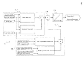
- a DPF failure detection device 1 detects a failure in a diesel particulate filter (referred to as "DPF" hereinafter) 4 that is arranged in an exhaust pipe 3 guiding exhaust gas from an internal combustion engine 2 to the atmosphere.
- DPF diesel particulate filter
- the DPF failure detection device 1 has: a theoretical deposited amount calculator unit 5 that calculates the deposited amount of a particulate matter (referred to as "PM” hereinafter) on the DPF 4 (referred to as “theoretical deposited amount” hereinafter) from an operating state of the internal combustion engine 2; an electrical capacitance type PM sensor 6 that is configured by two electrodes disposed in the DPF 4; an actual deposited amount measuring unit 7 that measures the deposited amount of the PM on the DPF 4 (referred to as “actual deposited amount” hereinafter) based on an electrical capacitance of the electrical capacitance type PM sensor 6; and a failure diagnosis unit 8 that determines that the DPF 4 has a failure, when a divergence of the actual deposited amount from the theoretical deposited amount exceeds an allowable limit, the actual deposited amount being measured by the actual deposited amount measuring unit 7 and the theoretical deposited amount being calculated by the theoretical deposited amount calculator 5.
- a theoretical deposited amount calculator unit 5 that calculates the deposited amount of a part
- the internal combustion engine 2 is a diesel engine.
- An intake pipe 9 for supplying air to the internal combustion engine 2 is provided with a MAF sensor 10 for detecting the amount of intake air, a compressor 11 of a turbocharger, and an intake air cooler 12, which are disposed sequentially starting from the atmosphere side.
- the exhaust pipe 3 is provided with a turbine 13 of the turbocharger and the DPF 4, which are disposed sequentially starting from the internal combustion engine 2 side.
- An EGR device 14 for circulating the exhaust gas to the admission at an appropriate EGR rate is disposed between an exhaust manifold and an intake manifold of the internal combustion engine 2.
- the DPF 4 is a conventionally known ceramic filter and has a number of honeycomb holes. In the present invention, however, the DPF 4 is provided with an electrode of the electrical capacitance type PM sensor 6.
- the theoretical deposited amount calculator unit 5 has a PM generation amount calculator 21 for calculating the amount of PM generated by the internal combustion engine 2, a PM regeneration amount calculator 22 for calculating the amount of PM regenerated passively in the DPF 4, and a deduction calculator 23 used for deducting the amount of PM regenerated from the amount of PM generated to calculate the theoretical deposited amount.
- the PM generation amount calculator 21 calculates the basic amount of PM (basic amount) generated by the internal combustion engine 2 on the basis of an engine speed, the amount of fuel, and an EGR rate.
- the PM generation amount calculator 21 further calculates the transient amount of PM (transient amount) generated by the internal combustion engine 2 on the basis of the engine speed, the amount of fuel, and an air-fuel ratio, and calculates the amount of PM generated (PMi) as a sum of the basic amount and the transient amount. It is preferred that an approximation formula obtained by experiment or a map obtained by experiment be used in each of these calculations.
- the PM regeneration amount calculator 22 calculates the amount of PM regenerated by heat in the DPF 4 (heat regeneration amount) on the basis of the air-fuel ratio, the amount of oxygen, and a DPF temperature.
- the PM regeneration amount calculator 22 further calculates the amount of PM regenerated by reacting with NO 2 (NOx reduction, PM oxidation) (NO 2 regeneration amount) on the basis of the amount of NO 2 generated, an exhaust gas temperature, and an exhaust gas volume, and calculates the amount of PM regenerated (PMr) as a sum of the heat regeneration amount and the NO 2 regeneration amount. It is preferred that an approximation formula obtained by experiment or a map obtained by experiment be used in each of these calculations.
- the deduction calculator 23 has a difference unit 24 for obtaining a difference between the amount of PM generated (PMi) and the amount of PM regenerated (PMr), and an accumulation unit 25 for accumulating the difference, while the internal combustion engine 2 is operated.
- the amount of PM that should be deposited on the DPF 4, or the theoretical deposited amount PMb is obtained as a result of the accumulation of the difference between the amount of PM generated (PMi) and the amount of PM regenerated (PMr).
- the theoretical deposited amount PMb is obtained in the following arithmetic expression.
- DPF forced regeneration takes place.
- the exhaust gas temperature is increased by the fuel injection control where additional fuel injection is performed, if needed, after main fuel injection in the internal combustion engine 2, thereby combusting and removing the PM deposited on the DPF 4.
- the theoretical deposited amount PMb is cleared at the time of the DPF forced regeneration so that new accumulation of the difference is started.
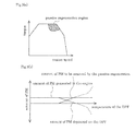
- the passive regeneration removes the PM on the DPF 4 without carrying out any special regeneration control. For instance, as shown in a passive regeneration region in Fig. 3(a) , in an engine state where the engine speed is high and the torque is large, the exhaust gas temperature is significantly high, thereby combusting the PM accumulated on the DPF 4. This is called heat regeneration. In addition, because the exhaust gas temperature is high, the PM is oxidized by reacting the PM with NO 2 of the exhaust gas, thereby causing NO 2 regeneration.
- the amount of PM to be removed by the passive regeneration increases as the temperature of the DPF 4 rises, reducing the amount of PM deposited on the DPF 4.
- the amount of PM regenerated due to the exhaust gas temperature corresponds to the abovementioned heat regeneration amount and NO 2 regeneration amount.
- C represents the electrical capacitance, ⁇ a permittivity, S an electrode area, and d an interelectrode distance.
- the electrical capacitance type PM sensor 6 is characterized in that the electrical capacitance increases in proportion to the increase in the deposited amount of PM collected in the DPF 4, as shown in Fig. 4 .
- An electrical capacitance type PM sensor 6a shown in Fig. 5(a) is provided with one electrode 51, in the shape of a piece of a cylinder, disposed along one-half of an outer circumference of the cylindrical DPF 4 and another electrode 52, also in the shape of a piece of a cylinder, disposed along the other half. Therefore, the two electrodes 51 and 52 face each other with the DPF 4 therebetween. When the PM is collected by the DPF 4, the electrical capacitance changes under the influence of the PM existing between the electrodes 51 and 52.
- An electrical capacitance type PM sensor 6b shown in Fig. 5(b) is provided with one cylindrical electrode 53 so as to cover the entire outer circumference of the cylindrical DPF 4 and another cylindrical electrode 54 disposed at a core of the DPF 4. Therefore, the two electrodes 53 and 54 are disposed concentrically inside and outside the DPF 4. When the PM is collected by the DPF 4, the electrical capacitance changes under the influence of the PM existing between the electrodes 53 and 54.
- An electrical capacitance type PM sensor 6c shown in Fig. 5(c) is provided with one cylindrical electrode 55 so as to cover the entire outer circumference of the cylindrical DPF 4 and another electrode 56 configured by a plurality of wires disposed to form a cylinder in the core of the DPF 4.
- An electrical capacitance type PM sensor 6d shown in Fig. 5(d) is provided with two mesh electrodes 57 and 58 disposed at an upstream side and downstream side of the cylindrical DPF 4 respectively.
- the actual deposited amount measuring unit 7 has a measurement map that is set based on the characteristics shown in Fig. 4 and detects the electrical capacitance of the electrical capacitance type PM sensor 6 to measure the deposited amount of PM based on the detected electrical capacitance with reference to the measurement map.
- the actual deposited amount measuring unit 7 uses a variable capacitor capable of controlling the electrical capacitance within an appropriate electrical capacitance range, to detect an electrical equilibrium between the electrical capacitance type PM sensor 6 and the variable capacitor while sweeping an electrical capacitance of the variable capacitor in the abovementioned range, and then reads an electrical capacitance control value of the variable capacitor as the electrical capacitance of the electrical capacitance type PM sensor 6 once the equilibrium is achieved.
- the failure diagnosis unit 8 obtains the divergence of the actual deposited amount from the theoretical deposited amount, the actual deposited amount being measured by the actual deposited amount measuring unit 7 and the theoretical deposited amount being calculated by the theoretical deposited amount calculator 5, and determines that the DPF 4 has a failure, when the divergence exceeds the allowable limit. Specifically, the failure diagnosis unit 8 calculates the difference between the theoretical deposited amount and the actual deposited amount or calculates a difference between an increase rate of the theoretical deposited amount and an increase rate of the actual deposited amount when the actual deposited amount is smaller than the theoretical deposited amount. When the difference between the theoretical deposited amount and the actual deposited amount is equal to or greater than a predetermined value, or when the difference in the increase rate is equal to or greater than the predetermined value, the failure diagnosis unit 8 determines that the DPF 4 has a failure.
- the failure diagnosis unit 8 calculates the difference between the actual deposited amount and the theoretical deposited amount or calculates the difference between the increase rate of the actual deposited amount and the increase rate of the theoretical deposited amount.
- the failure diagnosis unit 8 determines that there is an engine failure in which a large amount of PM is discharged.
- the theoretical deposited amount calculator 5, the actual deposited amount measuring unit 7, and the failure diagnosis unit 8 be realized by a digital circuit operated by a program and be incorporated in an electronic control unit (ECU) that controls the fuel injection, transmission, and the like of the vehicle.
- ECU electronice control unit
- the theoretical deposited amount increases with time. In this embodiment, however, for the sake of convenience, given that the engine state is constant, the theoretical deposited amount increased linearly. Moreover, given that the DPF 4 is in an excellent condition, the actual deposited amount also increases in the same manner as the theoretical deposited amount. Note in each diagram that the theoretical deposited amount is shifted from the actual deposited amount, in order to distinguish therebetween; however, in reality the actual deposited amount and the theoretical deposited amount overlap on each other.
- the increase of the actual deposited amount slows down, when a failure occurs in the DPF 4 and causes the PM to flow out to the downstream side of the DPF 4.
- the actual deposited amount stops increasing from the point when the failure occurs (shown in the circle).
- the difference between the actual deposited amount and the theoretical deposited amount grows (shown in the ellipse).
- the failure diagnosis unit 8 determines that the DPF 4 has a failure.
- the failure diagnosis unit 8 may determine that the DPF 4 has a failure, when the difference in increase rate between the actual deposited amount and the theoretical deposited amount is equal to or greater than the predetermined value.
- the failure diagnosis unit 8 determines that the DPF 4 has a failure, when the difference between the actual deposited amount and the theoretical deposited amount is equal to or greater than the predetermined value or when the difference in increase rate is equal to or greater than the predetermined value.
- the failure diagnosis unit 8 can determine that a failure that may generate a large volume of PM in the internal combustion engine 2 has occurred.
- the failure diagnosis unit 8 determines that the DPF 4 has a failure.
- the failure diagnosis unit 8 determines that the internal combustion engine 2 has a failure.
- failure diagnosis unit 8 determines that the DPF 4 has a failure
- audio-visual means notifies a driver of the result of the determination to enable prompt response to the determination.
- the DPF failure detection method (or the DPF failure detection device 1) of the present invention calculates the theoretical deposited amount of the PM on the DPF 4 from the operating state of the internal combustion engine 2, measures the actual deposited amount of the PM on the DPF 4 based on the electrical capacitance of the electrical capacitance type PM sensor 6, and determines that the DPF 4 has a failure, when the divergence of the actual deposited amount from the theoretical deposited amount exceeds the allowable limit. Therefore, unlike the technology disclosed in Patent Document 1, a failure can be detected with a simple configuration and at low cost. In other words, because high voltages are not required in the electrical capacitance type PN sensor 6 and an extremely simple configuration can be obtained, the technology of the present invention does not require any safety measures for electrical insulation or any countermeasures for radiation noise and therefore can be realized at low cost.
Landscapes
- Engineering & Computer Science (AREA)
- Chemical & Material Sciences (AREA)
- Combustion & Propulsion (AREA)
- Mechanical Engineering (AREA)
- General Engineering & Computer Science (AREA)
- Chemical Kinetics & Catalysis (AREA)
- Processes For Solid Components From Exhaust (AREA)
Abstract
Description
- The present invention relates to a DPF failure detection method and a DPF failure detection device for detecting a failure in a DPF for collecting PM of exhaust gas in an internal combustion engine. More particularly, the present invention relates to a DPF failure detection method and a DPF failure detection device that can be realized with a simple configuration and detect a failure at low cost.
- In a vehicle equipped with an internal combustion engine such as a diesel engine, an exhaust pipe for guiding exhaust gas from the internal combustion engine to the atmosphere has a diesel particulate filter (DPF), wherein a particulate matter (PM) such as soot contained in the exhaust gas is collected. The DPF, mainly made of ceramic, is a filter that has a number of honeycomb holes (or square holes). In the DPF, the PM adheres to the surface of the honeycomb holes serving as passages for the exhaust gas, whereby the PM is collected.
- However, if the DPF is damaged or cracks, then the DPF cannot collect the PM sufficiently, causing the PM to flow out to the downstream side of the DPF and releasing the PM to the atmosphere. In order to prevent this defect, it is desired that a failure in the DPF be detected and handled promptly. In view of such circumstances, in the U.S., it is mandated under the OBD (on-board diagnosis) regulation that a vehicle be equipped with a DPF failure detection monitor.
- In conventional technologies, mainly a differential pressure sensor for measuring a difference in pressure in front of and behind a DPF is installed, wherein when an output value of the differential pressure sensor significantly falls below an output range of a normal state of the DPF, it is determined that the DPF has a failure. However, there is a possibility that a method using such a differential pressure sensor has a problem in its detection accuracy and cannot cope with the regulations that become tighter in the future. Therefore, there has been known the technology disclosed in Patent Document 1 as a PM sensor for detecting the amount of PM in exhaust gas.
- Patent Document 1: Japanese Patent Application Publication No.
2006-153716 - However, the PM sensor disclosed in Patent Document 1 is a fixed equipment used for research and development of internal combustion engines and is not suitable to be installed in a vehicle.
- For instance, although a DPF failure detection device to be installed in a vehicle needs to be small, the PM sensor disclosed in Patent Document 1 consumes a high voltage reaching as much as 2000 to 7000 V and. Such a device tends to be massive in size, weighty, and expensive.
- Furthermore, the PM sensor of Patent Document 1 consumes high voltages and therefore needs to devise safety measures for electrical insulation, again causing a cost increase. An additional concern is that radiation noise is caused due to the consumption of high voltages.
- Therefore, an object of the present invention is to solve the problems described above and to provide a DPF failure detection method and a DPF failure detection device that can be realized with a simple configuration and detect a failure at low cost.
- A DPF failure detection method of the present invention for achieving the object described above is a diesel particulate filter (referred to as "DPF" hereinafter) failure detection method for detecting a failure in a DPF that is arranged in an exhaust pipe guiding exhaust gas from an internal combustion engine to the atmosphere, this DPF failure detection method including: calculating a deposited amount (referred to as "theoretical deposited amount" hereinafter) of a particulate matter (referred to as "PM" hereinafter) deposited on the DPF from an operating state of the internal combustion engine; measuring a deposited amount (referred to as "actual deposited amount" hereinafter) of the PM on the DPF based on an electrical capacitance of an electrical capacitance type PM sensor configured by two electrodes disposed in the DPF; and determining that the DPF has a failure, when a divergence of the actual deposited amount from the theoretical deposited amount exceeds an allowable limit.
- A DPF failure detection device of the present invention is a diesel particulate filter (referred to as "DPF" hereinafter) failure detection device for detecting a failure in a DPF that is arranged in an exhaust pipe guiding exhaust gas from an internal combustion engine to the atmosphere, this DPF failure detection device including: a theoretical deposited amount calculator that calculates a deposited amount (referred to as "theoretical deposited amount" hereinafter) of a particulate matter (referred to as "PM" hereinafter) on the DPF from an operating state of the internal combustion engine; an electrical capacitance type PM sensor that is configured by two electrodes disposed in the DPF; an actual deposited amount measuring unit that measures a deposited amount referred to as "actual deposited amount" hereinafter) of the PM on the DPF (based on an electrical capacitance of the electrical capacitance type PM sensor; and a failure diagnosis unit that determines that the DPF has a failure, when a divergence of the actual deposited amount from the theoretical deposited amount exceeds an allowable limit, the actual deposited amount being measured by the actual deposited amount measuring unit while the theoretical deposited amount being calculated by the theoretical deposited amount calculator.
- The theoretical deposited amount calculator may have a PM generation amount calculator that calculates an amount of PM generated in the internal combustion engine; a PM regeneration amount calculator that calculates an amount of PM regenerated passively in the DPF; and a deduction calculator that deducts the amount of PM regenerated from the amount of PM generated in order to calculate the theoretical deposited amount.
- The PM generation amount calculator may calculate a basic amount of PM (basic amount) generated by the internal combustion engine on the basis of an engine speed, an amount of fuel, and an EGR rate, calculate a transient amount of PM (transient amount) generated by the internal combustion engine on the basis of the engine speed, the amount of fuel, and an air-fuel ratio, and calculate the amount of PM generated as a sum of the basic amount and the transient amount.
- The PM regeneration amount calculator may calculate an amount of PM regenerated by heat in the DPF (heat regeneration amount) on the basis of the air-fuel ratio, an amount of oxygen, and a DPF temperature, calculate an amount of PM regenerated by reacting with NO2 (NO2 regeneration amount) on the basis of an amount of NO2 generated, an exhaust gas temperature, and an exhaust gas volume, and calculate the amount of PM regenerated (PMr) as a sum of the heat regeneration amount and the NO2 regeneration amount.
- The deduction calculator may be configured by a difference unit for obtaining a difference between the amount of PM generated and the amount of PM regenerated, and an accumulation unit for accumulating the difference while the internal combustion engine is operated, wherein the theoretical deposited amount is obtained as a result of the accumulation of the difference between the amount of PM generated and the amount of PM regenerated, and wherein new accumulation of the difference is started after the theoretical deposited amount is cleared at the time of DPF forced regeneration.
- The electrical capacitance type PM sensor may be provided with one electrode disposed along one side of the DPF and another electrode disposed along the other side of the DPF.
- The electrical capacitance type PM sensor may be provided with one cylindrical electrode so as to cover the entire DPF and another cylindrical electrode disposed at a core of the DPF.
- The electrical capacitance type PM sensor may be provided with one cylindrical electrode so as to cover the entire DPF and another electrode configured by a plurality of wires disposed at the core of the DPF.
- The electrical capacitance type PM sensor may be provided with mesh electrodes disposed at an upstream side and downstream side of the DPF.
- The present invention has the following excellent effects.
- (1) The present invention can be realized with a simple configuration.
- (2) The present invention can detect a failure at low cost.
-
-
Fig. 1 is a configuration diagram of a DPF failure detection device according to an embodiment of the present invention; -
Fig. 2 is a block diagram showing details of calculation performed by a theoretical deposited amount calculator of the DPF failure detection device according to the present invention; -
Fig. 3(a) is an engine state graph showing engine speeds and torques two-dimensionally, andFig. 3(b) is a graph showing a correlation with a PM amount to a DPF temperature; -
Fig. 4 is a characteristic diagram of an electrical capacitance type PM sensor used in the DPF failure detection device according to the present invention; -
Figs. 5(a) to 5(d) are schematic configuration diagrams each showing a PM sensor used in the DPF failure detection device according to the present invention; and -
Figs. 6(a) to 6(d) are graphs each showing changes in the theoretical deposited amount and the actual deposited amount which are obtained in the DPF failure detection device according to the present invention, andFig. 6(e) is a block diagram of a failure diagnosis unit. - An embodiment of the present invention is described hereinafter with reference to the accompanying drawings.
- As shown in
Fig. 1 , a DPF failure detection device 1 according to the present invention detects a failure in a diesel particulate filter (referred to as "DPF" hereinafter) 4 that is arranged in an exhaust pipe 3 guiding exhaust gas from aninternal combustion engine 2 to the atmosphere. The DPF failure detection device 1 has: a theoretical depositedamount calculator unit 5 that calculates the deposited amount of a particulate matter (referred to as "PM" hereinafter) on the DPF 4 (referred to as "theoretical deposited amount" hereinafter) from an operating state of theinternal combustion engine 2; an electrical capacitancetype PM sensor 6 that is configured by two electrodes disposed in the DPF 4; an actual deposited amount measuring unit 7 that measures the deposited amount of the PM on the DPF 4 (referred to as "actual deposited amount" hereinafter) based on an electrical capacitance of the electrical capacitancetype PM sensor 6; and a failure diagnosis unit 8 that determines that the DPF 4 has a failure, when a divergence of the actual deposited amount from the theoretical deposited amount exceeds an allowable limit, the actual deposited amount being measured by the actual deposited amount measuring unit 7 and the theoretical deposited amount being calculated by the theoretical depositedamount calculator 5. - The
internal combustion engine 2 is a diesel engine. An intake pipe 9 for supplying air to theinternal combustion engine 2 is provided with a MAF sensor 10 for detecting the amount of intake air, acompressor 11 of a turbocharger, and anintake air cooler 12, which are disposed sequentially starting from the atmosphere side. The exhaust pipe 3 is provided with aturbine 13 of the turbocharger and the DPF 4, which are disposed sequentially starting from theinternal combustion engine 2 side. AnEGR device 14 for circulating the exhaust gas to the admission at an appropriate EGR rate is disposed between an exhaust manifold and an intake manifold of theinternal combustion engine 2. - The DPF 4 is a conventionally known ceramic filter and has a number of honeycomb holes. In the present invention, however, the DPF 4 is provided with an electrode of the electrical capacitance
type PM sensor 6. - As shown in
Fig. 2 , the theoretical depositedamount calculator unit 5 has a PM generation amount calculator 21 for calculating the amount of PM generated by theinternal combustion engine 2, a PMregeneration amount calculator 22 for calculating the amount of PM regenerated passively in the DPF 4, and adeduction calculator 23 used for deducting the amount of PM regenerated from the amount of PM generated to calculate the theoretical deposited amount. - The PM generation amount calculator 21 calculates the basic amount of PM (basic amount) generated by the
internal combustion engine 2 on the basis of an engine speed, the amount of fuel, and an EGR rate. The PM generation amount calculator 21 further calculates the transient amount of PM (transient amount) generated by theinternal combustion engine 2 on the basis of the engine speed, the amount of fuel, and an air-fuel ratio, and calculates the amount of PM generated (PMi) as a sum of the basic amount and the transient amount. It is preferred that an approximation formula obtained by experiment or a map obtained by experiment be used in each of these calculations. - The PM
regeneration amount calculator 22 calculates the amount of PM regenerated by heat in the DPF 4 (heat regeneration amount) on the basis of the air-fuel ratio, the amount of oxygen, and a DPF temperature. The PMregeneration amount calculator 22 further calculates the amount of PM regenerated by reacting with NO2 (NOx reduction, PM oxidation) (NO2 regeneration amount) on the basis of the amount of NO2 generated, an exhaust gas temperature, and an exhaust gas volume, and calculates the amount of PM regenerated (PMr) as a sum of the heat regeneration amount and the NO2 regeneration amount. It is preferred that an approximation formula obtained by experiment or a map obtained by experiment be used in each of these calculations. - The
deduction calculator 23 has adifference unit 24 for obtaining a difference between the amount of PM generated (PMi) and the amount of PM regenerated (PMr), and anaccumulation unit 25 for accumulating the difference, while theinternal combustion engine 2 is operated. The amount of PM that should be deposited on the DPF 4, or the theoretical deposited amount PMb, is obtained as a result of the accumulation of the difference between the amount of PM generated (PMi) and the amount of PM regenerated (PMr). The theoretical deposited amount PMb is obtained in the following arithmetic expression. -

- In a vehicle equipped with the DPF 4, so-called DPF forced regeneration takes place. In the DPF forced regeneration, the exhaust gas temperature is increased by the fuel injection control where additional fuel injection is performed, if needed, after main fuel injection in the
internal combustion engine 2, thereby combusting and removing the PM deposited on the DPF 4. On the basis of the arithmetic expression above, the theoretical deposited amount PMb is cleared at the time of the DPF forced regeneration so that new accumulation of the difference is started. - The passive regeneration, on the other hand, removes the PM on the DPF 4 without carrying out any special regeneration control. For instance, as shown in a passive regeneration region in
Fig. 3(a) , in an engine state where the engine speed is high and the torque is large, the exhaust gas temperature is significantly high, thereby combusting the PM accumulated on the DPF 4. This is called heat regeneration. In addition, because the exhaust gas temperature is high, the PM is oxidized by reacting the PM with NO2 of the exhaust gas, thereby causing NO2 regeneration. - As shown in
Fig. 3(b) , given that the amount of PM generated in theinternal combustion engine 2 is constant, the amount of PM to be removed by the passive regeneration increases as the temperature of the DPF 4 rises, reducing the amount of PM deposited on the DPF 4. The amount of PM regenerated due to the exhaust gas temperature (the DPF temperature) corresponds to the abovementioned heat regeneration amount and NO2 regeneration amount. - In the electrical capacitance
type PM sensor 6 shown inFig. 1 , the electrical capacitance between two electrodes provided in the DPF 4 changes according to the deposited amount of PM collected. In other words, the following relationship is satisfied: -

- In this expression, C represents the electrical capacitance, ε a permittivity, S an electrode area, and d an interelectrode distance. This expression follows the principle where the electrical capacitance C increases as the PM increases in a medium between the electrodes and the permittivity ε becomes high.
- Therefore, the electrical capacitance
type PM sensor 6 is characterized in that the electrical capacitance increases in proportion to the increase in the deposited amount of PM collected in the DPF 4, as shown inFig. 4 . - An electrical capacitance
type PM sensor 6a shown inFig. 5(a) is provided with one electrode 51, in the shape of a piece of a cylinder, disposed along one-half of an outer circumference of the cylindrical DPF 4 and anotherelectrode 52, also in the shape of a piece of a cylinder, disposed along the other half. Therefore, the twoelectrodes 51 and 52 face each other with the DPF 4 therebetween. When the PM is collected by the DPF 4, the electrical capacitance changes under the influence of the PM existing between theelectrodes 51 and 52. - An electrical capacitance type PM sensor 6b shown in
Fig. 5(b) is provided with one cylindrical electrode 53 so as to cover the entire outer circumference of the cylindrical DPF 4 and anothercylindrical electrode 54 disposed at a core of the DPF 4. Therefore, the twoelectrodes 53 and 54 are disposed concentrically inside and outside the DPF 4. When the PM is collected by the DPF 4, the electrical capacitance changes under the influence of the PM existing between theelectrodes 53 and 54. - An electrical capacitance
type PM sensor 6c shown inFig. 5(c) is provided with onecylindrical electrode 55 so as to cover the entire outer circumference of the cylindrical DPF 4 and anotherelectrode 56 configured by a plurality of wires disposed to form a cylinder in the core of the DPF 4. - An electrical capacitance type PM sensor 6d shown in
Fig. 5(d) is provided with twomesh electrodes - The embodiment is described with reference to
Fig. 1 again. - The actual deposited amount measuring unit 7 has a measurement map that is set based on the characteristics shown in
Fig. 4 and detects the electrical capacitance of the electrical capacitancetype PM sensor 6 to measure the deposited amount of PM based on the detected electrical capacitance with reference to the measurement map. For example, the actual deposited amount measuring unit 7 uses a variable capacitor capable of controlling the electrical capacitance within an appropriate electrical capacitance range, to detect an electrical equilibrium between the electrical capacitancetype PM sensor 6 and the variable capacitor while sweeping an electrical capacitance of the variable capacitor in the abovementioned range, and then reads an electrical capacitance control value of the variable capacitor as the electrical capacitance of the electrical capacitancetype PM sensor 6 once the equilibrium is achieved. - The failure diagnosis unit 8 obtains the divergence of the actual deposited amount from the theoretical deposited amount, the actual deposited amount being measured by the actual deposited amount measuring unit 7 and the theoretical deposited amount being calculated by the theoretical deposited
amount calculator 5, and determines that the DPF 4 has a failure, when the divergence exceeds the allowable limit. Specifically, the failure diagnosis unit 8 calculates the difference between the theoretical deposited amount and the actual deposited amount or calculates a difference between an increase rate of the theoretical deposited amount and an increase rate of the actual deposited amount when the actual deposited amount is smaller than the theoretical deposited amount. When the difference between the theoretical deposited amount and the actual deposited amount is equal to or greater than a predetermined value, or when the difference in the increase rate is equal to or greater than the predetermined value, the failure diagnosis unit 8 determines that the DPF 4 has a failure. - When the actual deposited amount is greater than the theoretical deposited amount, the failure diagnosis unit 8 calculates the difference between the actual deposited amount and the theoretical deposited amount or calculates the difference between the increase rate of the actual deposited amount and the increase rate of the theoretical deposited amount. When the difference between the theoretical deposited amount and the actual deposited amount is equal to or greater than the predetermined value or when the difference in the increase rate is equal to or greater than the predetermined value, the failure diagnosis unit 8 determines that there is an engine failure in which a large amount of PM is discharged.
- It is preferred that the theoretical deposited
amount calculator 5, the actual deposited amount measuring unit 7, and the failure diagnosis unit 8 be realized by a digital circuit operated by a program and be incorporated in an electronic control unit (ECU) that controls the fuel injection, transmission, and the like of the vehicle. - Operations of the DPF failure detection device 1 of the present invention are described hereinafter.
- As shown in
Fig. 6(a) , the theoretical deposited amount increases with time. In this embodiment, however, for the sake of convenience, given that the engine state is constant, the theoretical deposited amount increased linearly. Moreover, given that the DPF 4 is in an excellent condition, the actual deposited amount also increases in the same manner as the theoretical deposited amount. Note in each diagram that the theoretical deposited amount is shifted from the actual deposited amount, in order to distinguish therebetween; however, in reality the actual deposited amount and the theoretical deposited amount overlap on each other. - As shown in
Fig. 6(b) , the increase of the actual deposited amount slows down, when a failure occurs in the DPF 4 and causes the PM to flow out to the downstream side of the DPF 4. In the illustrated example, the actual deposited amount stops increasing from the point when the failure occurs (shown in the circle). As a result, the difference between the actual deposited amount and the theoretical deposited amount grows (shown in the ellipse). When the difference becomes equal to or greater than a predetermined value, the failure diagnosis unit 8 determines that the DPF 4 has a failure. Alternatively, the failure diagnosis unit 8 may determine that the DPF 4 has a failure, when the difference in increase rate between the actual deposited amount and the theoretical deposited amount is equal to or greater than the predetermined value. - As shown in
Fig. 6(c) , when the DPF 4 has a failure from the beginning, the theoretical deposited amount increases linearly at a constant increase rate, whereas the actual deposited amount increases linearly at a low increase rate. In this case as well, the failure diagnosis unit 8 determines that the DPF 4 has a failure, when the difference between the actual deposited amount and the theoretical deposited amount is equal to or greater than the predetermined value or when the difference in increase rate is equal to or greater than the predetermined value. - As shown in
Fig. 6(d) , when a large amount of PM is generated in theinternal combustion engine 2, the actual deposited amount increases more significantly than the theoretical deposited amount. As a result, the difference therebetween grows (shown by the ellipse). When the difference becomes equal to or greater than the predetermined value, the failure diagnosis unit 8 can determine that a failure that may generate a large volume of PM in theinternal combustion engine 2 has occurred. - As shown in
Fig. 6(e) , when the actual deposited amount is smaller than the theoretical deposited amount, and when the difference between the theoretical deposited amount and the actual deposited amount is equal to or greater than the predetermined value, the failure diagnosis unit 8 determines that the DPF 4 has a failure. When the actual deposited amount is greater than the theoretical deposited amount, and when the difference between the actual deposited amount and the theoretical deposited amount is equal to or greater than the predetermined value, the failure diagnosis unit 8 determines that theinternal combustion engine 2 has a failure. - Once the failure diagnosis unit 8 determines that the DPF 4 has a failure, audio-visual means notifies a driver of the result of the determination to enable prompt response to the determination.
- As described above, the DPF failure detection method (or the DPF failure detection device 1) of the present invention calculates the theoretical deposited amount of the PM on the DPF 4 from the operating state of the
internal combustion engine 2, measures the actual deposited amount of the PM on the DPF 4 based on the electrical capacitance of the electrical capacitancetype PM sensor 6, and determines that the DPF 4 has a failure, when the divergence of the actual deposited amount from the theoretical deposited amount exceeds the allowable limit. Therefore, unlike the technology disclosed in Patent Document 1, a failure can be detected with a simple configuration and at low cost. In other words, because high voltages are not required in the electrical capacitancetype PN sensor 6 and an extremely simple configuration can be obtained, the technology of the present invention does not require any safety measures for electrical insulation or any countermeasures for radiation noise and therefore can be realized at low cost. -
- 1 DPF failure detection device
- 2 internal combustion engine
- 3 exhaust pipe
- 4 diesel particulate filter (DPF)
- 5 theoretical deposited amount calculator
- 6 electrical capacitance type PM sensor
- 7 actual deposited amount measuring unit
- 8 failure diagnosis unit
Claims (10)
- A diesel particulate filter (referred to as "DPF" hereinafter) failure detection method for detecting a failure in a DPF that is arranged in an exhaust pipe guiding exhaust gas from an internal combustion engine to the atmosphere,
the DPF failure detection method comprising:calculating a deposited amount (referred to as "theoretical deposited amount" hereinafter) of a particulate matter (referred to as "PM" hereinafter) deposited on the DPF from an operating state of the internal combustion engine;measuring a deposited amount (referred to as "actual deposited amount" hereinafter) of the PM on the DPF based on an electrical capacitance of an electrical capacitance type PM sensor configured by two electrodes disposed in the DPF, anddetermining that the DPF has a failure, when a divergence of the actual deposited amount from the theoretical deposited amount exceeds an allowable limit. - A diesel particulate filter (referred to as "DPF" hereinafter) failure detection device for detecting a failure in a DPF that is arranged in an exhaust pipe guiding exhaust gas from an internal combustion engine to the atmosphere,
the DPF failure detection device comprising:a theoretical deposited amount calculator that calculates a deposited amount (referred to as "theoretical deposited amount" hereinafter) of a particulate matter (referred to as "PM" hereinafter) on the DPF from an operating state of the internal combustion engine;an electrical capacitance type PM sensor that is configured by two electrodes disposed in the DPF;an actual deposited amount measuring unit that measures a deposited amount referred to as "actual deposited amount" hereinafter) of the PM on the DPF (based on an electrical capacitance of the electrical capacitance type PM sensor; anda failure diagnosis unit that determines that the DPF has a failure, when a divergence of the actual deposited amount from the theoretical deposited amount exceeds an allowable limit, the actual deposited amount being measured by the actual deposited amount measuring unit while the theoretical deposited amount being calculated by the theoretical deposited amount calculator. - The DPF failure detection device according to claim 2, wherein
the theoretical deposited amount calculator has:a PM generation amount calculator that calculates an amount of PM generated in the internal combustion engine;a PM regeneration amount calculator that calculates an amount of PM regenerated passively in the DPF; anda deduction calculator that deducts the amount of PM regenerated from the amount of PM generated in order to calculate the theoretical deposited amount. - The DPF failure detection device according to claim 3, wherein
the PM generation amount calculator:calculates a basic amount of PM (basic amount) generated by the internal combustion engine on the basis of an engine speed, an amount of fuel, and an EGR rate;calculates a transient amount of PM (transient amount) generated by the internal combustion engine on the basis of the engine speed, the amount of fuel, and an air-fuel ratio; andcalculates the amount of PM generated as a sum of the basic amount and the transient amount. - The DPF failure detection device according to claim 3 or 4, wherein
the PM regeneration amount calculator:calculates an amount (heat regeneration amount) of PM regenerated by heat in the DPF on the basis of the air-fuel ratio, an amount of oxygen, and a DPF temperature;calculates an amount (NO2 regeneration amount) of PM regenerated by reacting with NO2 on the basis of an amount of NO2 generated, an exhaust gas temperature, and an exhaust gas volume; andcalculates the amount of PM regenerated (PMr) as a sum of the heat regeneration amount and the NO2 regeneration amount. - The DPF failure detection device according to any of claims 3 to 5, wherein
the deduction calculator is configured by a difference unit for obtaining a difference between the amount of PM generated and the amount of PM regenerated, and an accumulation unit for accumulating the difference while the internal combustion engine is operated,
the theoretical deposited amount is obtained as a result of the accumulation of the difference between the amount of PM generated and the amount of PM regenerated, and
new accumulation of the difference is started after the theoretical deposited amount is cleared at the time of DPF forced regeneration. - The DPF failure detection device according to any of claims 2 to 6, wherein the electrical capacitance type PM sensor is provided with one electrode disposed along one side of the DPF and another electrode disposed along the other side of the DPF.
- The DPF failure detection device according to any of claims 2 to 6, wherein the electrical capacitance type PM sensor is provided with one cylindrical electrode so as to cover the entire DPF and another cylindrical electrode disposed at a core of the DPF.
- The DPF failure detection device according to any of claims 2 to 6, wherein the electrical capacitance type PM sensor is provided with one cylindrical electrode so as to cover the entire DPF and another electrode configured by a plurality of wires disposed at the core of the DPF.
- The DPF failure detection device according to any of claims 2 to 6, wherein the electrical capacitance type PM sensor is provided with mesh electrodes disposed at an upstream side and downstream side of the DPF.
Applications Claiming Priority (2)
| Application Number | Priority Date | Filing Date | Title |
|---|---|---|---|
| JP2010053426A JP5565005B2 (en) | 2010-03-10 | 2010-03-10 | DPF failure detection method and DPF failure detection device |
| PCT/JP2011/054765 WO2011111584A1 (en) | 2010-03-10 | 2011-03-02 | Dpf failure detection method and dpf failure detection device |
Publications (3)
| Publication Number | Publication Date |
|---|---|
| EP2546484A1 true EP2546484A1 (en) | 2013-01-16 |
| EP2546484A4 EP2546484A4 (en) | 2016-08-10 |
| EP2546484B1 EP2546484B1 (en) | 2017-12-27 |
Family
ID=44563388
Family Applications (1)
| Application Number | Title | Priority Date | Filing Date |
|---|---|---|---|
| EP11753243.2A Active EP2546484B1 (en) | 2010-03-10 | 2011-03-02 | Dpf failure detection method and dpf failure detection device |
Country Status (5)
| Country | Link |
|---|---|
| US (1) | US8770016B2 (en) |
| EP (1) | EP2546484B1 (en) |
| JP (1) | JP5565005B2 (en) |
| CN (1) | CN102869860B (en) |
| WO (1) | WO2011111584A1 (en) |
Cited By (3)
| Publication number | Priority date | Publication date | Assignee | Title |
|---|---|---|---|---|
| WO2015158376A1 (en) * | 2014-04-16 | 2015-10-22 | Continental Automotive Gmbh | Method for checking the functionality of a particle filter |
| EP2949893A4 (en) * | 2013-01-28 | 2016-09-21 | Isuzu Motors Ltd | Exhaust purification device for internal combustion engine |
| WO2019216901A1 (en) | 2018-05-10 | 2019-11-14 | Volvo Truck Corporation | Method and system for assessing engine faults |
Families Citing this family (22)
| Publication number | Priority date | Publication date | Assignee | Title |
|---|---|---|---|---|
| JP2013104416A (en) * | 2011-11-16 | 2013-05-30 | Mitsubishi Heavy Ind Ltd | Device for estimating pm accumulation quantity in dpf |
| JP2013148045A (en) * | 2012-01-20 | 2013-08-01 | Mitsubishi Heavy Ind Ltd | Exhaust emission control system of engine |
| JP6136298B2 (en) * | 2013-01-28 | 2017-05-31 | いすゞ自動車株式会社 | Exhaust gas purification device for internal combustion engine |
| JP6136351B2 (en) * | 2013-02-22 | 2017-05-31 | いすゞ自動車株式会社 | Exhaust gas purification device for internal combustion engine |
| JP6197377B2 (en) * | 2013-06-03 | 2017-09-20 | いすゞ自動車株式会社 | Exhaust purification device |
| JP2015059476A (en) * | 2013-09-18 | 2015-03-30 | いすゞ自動車株式会社 | Exhaust purification system of internal combustion engine |
| JP2015059477A (en) * | 2013-09-18 | 2015-03-30 | いすゞ自動車株式会社 | Exhaust gas purification device for internal combustion engine |
| JP2015059478A (en) * | 2013-09-18 | 2015-03-30 | いすゞ自動車株式会社 | Exhaust gas purification device for internal combustion engine |
| JP2015075007A (en) * | 2013-10-08 | 2015-04-20 | いすゞ自動車株式会社 | Exhaust emission control system |
| JP6379837B2 (en) * | 2014-08-11 | 2018-08-29 | いすゞ自動車株式会社 | Sensor |
| US9399943B1 (en) | 2015-05-04 | 2016-07-26 | Ford Global Technologies, Llc | System and method for detecting particulate filter leakage |
| KR20160149898A (en) | 2015-06-19 | 2016-12-28 | 현대자동차주식회사 | Particulate matter sensor |
| US9551259B1 (en) * | 2015-08-26 | 2017-01-24 | Ford Global Technologies, Llc | Method and system for diesel particulate filter diagnostics |
| US9645068B2 (en) | 2015-10-13 | 2017-05-09 | Ford Global Technologies, Llc | Method and system for particulate filter leakage detection |
| US9551262B1 (en) * | 2015-10-13 | 2017-01-24 | Ford Global Technologies, Llc | Method and system for particulate filter leakage detection |
| JP6542913B2 (en) * | 2015-12-25 | 2019-07-10 | 京セラ株式会社 | Parts for measuring particulate matter |
| CN108279334A (en) * | 2017-12-29 | 2018-07-13 | 国网北京市电力公司 | Monitoring method and device, system |
| JP7076263B2 (en) * | 2018-03-30 | 2022-05-27 | 太陽インキ製造株式会社 | Curable resin compositions, dry films, cured products, and electronic components |
| US11333056B2 (en) | 2019-07-15 | 2022-05-17 | Fca Us Llc | Gasoline particulate filter brick detection techniques |
| CN110751749B (en) * | 2019-09-18 | 2021-08-20 | 中国第一汽车股份有限公司 | GPF ice blockage alarm prompting method, system, device and storage medium |
| CN110985166B (en) * | 2019-12-11 | 2021-03-16 | 潍柴动力股份有限公司 | Ash removal method and device |
| JP7516886B2 (en) * | 2020-06-09 | 2024-07-17 | 株式会社リコー | Powder detection system, toner storage device, and image forming apparatus |
Family Cites Families (11)
| Publication number | Priority date | Publication date | Assignee | Title |
|---|---|---|---|---|
| JP4260345B2 (en) * | 2000-07-03 | 2009-04-30 | 日産ディーゼル工業株式会社 | Diesel engine exhaust purification system |
| DE502005003454D1 (en) * | 2004-02-12 | 2008-05-08 | Daimler Ag | DEVICE FOR DETERMINING THE CONDITION OF A PARTICULAR FILTER |
| JP4470593B2 (en) * | 2004-06-03 | 2010-06-02 | 株式会社デンソー | Exhaust gas purification device for internal combustion engine |
| JP4544978B2 (en) | 2004-11-30 | 2010-09-15 | 株式会社堀場製作所 | Exhaust gas analyzer and soot measurement method |
| US7278304B2 (en) * | 2005-12-06 | 2007-10-09 | Ford Global Technologies Llc | System and method for performing a particulate sensor diagnostic |
| JP4855811B2 (en) * | 2006-03-28 | 2012-01-18 | 日本碍子株式会社 | Fine particle amount detection system |
| US20080155970A1 (en) * | 2006-12-27 | 2008-07-03 | Detroit Diesel Corporation | Method for verifying the functionality of the components of a diesel particulate filter system |
| JP4928335B2 (en) * | 2007-04-17 | 2012-05-09 | 日野自動車株式会社 | Exhaust purification device |
| DE102008015256A1 (en) * | 2008-03-20 | 2009-10-01 | Continental Automotive Gmbh | Diagnostic method and diagnostic system for a particle filter of an internal combustion engine, in particular for a soot filter in a diesel motor vehicle |
| US20120297750A1 (en) * | 2011-05-25 | 2012-11-29 | GM Global Technology Operations LLC | Method for monitoring an exhaust particulate filter |
| US9303579B2 (en) * | 2012-08-01 | 2016-04-05 | GM Global Technology Operations LLC | System and method for monitoring a particulate filter in a vehicle exhaust aftertreatment device |
-
2010
- 2010-03-10 JP JP2010053426A patent/JP5565005B2/en not_active Expired - Fee Related
-
2011
- 2011-03-02 US US13/579,122 patent/US8770016B2/en active Active
- 2011-03-02 WO PCT/JP2011/054765 patent/WO2011111584A1/en not_active Ceased
- 2011-03-02 CN CN201180013127.1A patent/CN102869860B/en active Active
- 2011-03-02 EP EP11753243.2A patent/EP2546484B1/en active Active
Non-Patent Citations (1)
| Title |
|---|
| See references of WO2011111584A1 * |
Cited By (7)
| Publication number | Priority date | Publication date | Assignee | Title |
|---|---|---|---|---|
| EP2949893A4 (en) * | 2013-01-28 | 2016-09-21 | Isuzu Motors Ltd | Exhaust purification device for internal combustion engine |
| WO2015158376A1 (en) * | 2014-04-16 | 2015-10-22 | Continental Automotive Gmbh | Method for checking the functionality of a particle filter |
| CN106460627A (en) * | 2014-04-16 | 2017-02-22 | 大陆汽车有限公司 | Method for checking the functionality of a particle filter |
| US10132218B2 (en) | 2014-04-16 | 2018-11-20 | Continental Automotive Gmbh | Exhaust system for a motor vehicle |
| CN106460627B (en) * | 2014-04-16 | 2019-04-30 | 大陆汽车有限公司 | Method for testing the functional capability of a particulate filter |
| WO2019216901A1 (en) | 2018-05-10 | 2019-11-14 | Volvo Truck Corporation | Method and system for assessing engine faults |
| EP3791052A4 (en) * | 2018-05-10 | 2022-01-26 | Volvo Truck Corporation | METHOD AND SYSTEM FOR ASSESSING ENGINE FAILURES |
Also Published As
| Publication number | Publication date |
|---|---|
| EP2546484B1 (en) | 2017-12-27 |
| US20120318055A1 (en) | 2012-12-20 |
| WO2011111584A1 (en) | 2011-09-15 |
| CN102869860A (en) | 2013-01-09 |
| CN102869860B (en) | 2014-12-31 |
| JP2011185213A (en) | 2011-09-22 |
| JP5565005B2 (en) | 2014-08-06 |
| EP2546484A4 (en) | 2016-08-10 |
| US8770016B2 (en) | 2014-07-08 |
Similar Documents
| Publication | Publication Date | Title |
|---|---|---|
| EP2546484B1 (en) | Dpf failure detection method and dpf failure detection device | |
| US7396389B2 (en) | Abnormality detection apparatus for exhaust gas purification apparatus for internal combustion engine | |
| US10041916B2 (en) | Method and device for monitoring gas sensors | |
| RU2582720C2 (en) | Engine operation method | |
| JP4389606B2 (en) | Exhaust gas purification device for internal combustion engine | |
| JP4403944B2 (en) | Exhaust gas purification device for internal combustion engine | |
| EP3048275A1 (en) | Diagnostic device | |
| US9695732B2 (en) | Diagnostic device | |
| CN110107386B (en) | Method for determining the amount of metal powder accumulated in a particulate filter suitable for an internal combustion engine | |
| EP2444608B1 (en) | Exhaust gas pressure loss calculation device for engine | |
| EP3190276B1 (en) | Engine control apparatus | |
| EP3056699B1 (en) | Exhaust purification system | |
| US9784200B2 (en) | Exhaust purification system | |
| EP2806124A1 (en) | Engine exhaust purification system | |
| JP6365319B2 (en) | PM sensor abnormality diagnosis device | |
| JP4432693B2 (en) | BACKGROUND OF THE INVENTION 1. Field of the Invention The present invention relates to an engine exhaust purification device, and more particularly to an improvement in a filter regeneration processing technique for collecting particulate matter in engine exhaust. | |
| CN102787887B (en) | Control device of internal combustion engine | |
| JP4894569B2 (en) | Temperature sensor failure diagnosis device | |
| JP5517879B2 (en) | PM emission estimation device and PM emission control device for diesel engine | |
| JP2007332905A (en) | Internal combustion engine temperature measurement device | |
| JP2015055167A (en) | Exhaust emission control device | |
| JP5915111B2 (en) | NOx sensor abnormality diagnosis method, NOx sensor abnormality diagnosis system, and NOx emission concentration estimation method for internal combustion engine | |
| Linke et al. | Concept for Diesel Particulate Filter monitoring based on BOSCH Particulate Matter Sensor (PMS) |
Legal Events
| Date | Code | Title | Description |
|---|---|---|---|
| PUAI | Public reference made under article 153(3) epc to a published international application that has entered the european phase |
Free format text: ORIGINAL CODE: 0009012 |
|
| 17P | Request for examination filed |
Effective date: 20120925 |
|
| AK | Designated contracting states |
Kind code of ref document: A1 Designated state(s): AL AT BE BG CH CY CZ DE DK EE ES FI FR GB GR HR HU IE IS IT LI LT LU LV MC MK MT NL NO PL PT RO RS SE SI SK SM TR |
|
| DAX | Request for extension of the european patent (deleted) | ||
| RA4 | Supplementary search report drawn up and despatched (corrected) |
Effective date: 20160711 |
|
| RIC1 | Information provided on ipc code assigned before grant |
Ipc: F01N 3/02 20060101AFI20160705BHEP |
|
| REG | Reference to a national code |
Ref country code: DE Ref legal event code: R079 Ref document number: 602011044551 Country of ref document: DE Free format text: PREVIOUS MAIN CLASS: F01N0003020000 Ipc: F02D0041220000 |
|
| GRAP | Despatch of communication of intention to grant a patent |
Free format text: ORIGINAL CODE: EPIDOSNIGR1 |
|
| STAA | Information on the status of an ep patent application or granted ep patent |
Free format text: STATUS: GRANT OF PATENT IS INTENDED |
|
| RIC1 | Information provided on ipc code assigned before grant |
Ipc: F02D 41/22 20060101AFI20170608BHEP |
|
| INTG | Intention to grant announced |
Effective date: 20170703 |
|
| GRAS | Grant fee paid |
Free format text: ORIGINAL CODE: EPIDOSNIGR3 |
|
| GRAA | (expected) grant |
Free format text: ORIGINAL CODE: 0009210 |
|
| STAA | Information on the status of an ep patent application or granted ep patent |
Free format text: STATUS: THE PATENT HAS BEEN GRANTED |
|
| AK | Designated contracting states |
Kind code of ref document: B1 Designated state(s): AL AT BE BG CH CY CZ DE DK EE ES FI FR GB GR HR HU IE IS IT LI LT LU LV MC MK MT NL NO PL PT RO RS SE SI SK SM TR |
|
| RAP1 | Party data changed (applicant data changed or rights of an application transferred) |
Owner name: ISUZU MOTORS LIMITED |
|
| REG | Reference to a national code |
Ref country code: GB Ref legal event code: FG4D |
|
| REG | Reference to a national code |
Ref country code: CH Ref legal event code: EP |
|
| REG | Reference to a national code |
Ref country code: AT Ref legal event code: REF Ref document number: 958523 Country of ref document: AT Kind code of ref document: T Effective date: 20180115 |
|
| REG | Reference to a national code |
Ref country code: IE Ref legal event code: FG4D |
|
| REG | Reference to a national code |
Ref country code: DE Ref legal event code: R096 Ref document number: 602011044551 Country of ref document: DE |
|
| REG | Reference to a national code |
Ref country code: FR Ref legal event code: PLFP Year of fee payment: 8 |
|
| PG25 | Lapsed in a contracting state [announced via postgrant information from national office to epo] |
Ref country code: NO Free format text: LAPSE BECAUSE OF FAILURE TO SUBMIT A TRANSLATION OF THE DESCRIPTION OR TO PAY THE FEE WITHIN THE PRESCRIBED TIME-LIMIT Effective date: 20180327 Ref country code: LT Free format text: LAPSE BECAUSE OF FAILURE TO SUBMIT A TRANSLATION OF THE DESCRIPTION OR TO PAY THE FEE WITHIN THE PRESCRIBED TIME-LIMIT Effective date: 20171227 Ref country code: FI Free format text: LAPSE BECAUSE OF FAILURE TO SUBMIT A TRANSLATION OF THE DESCRIPTION OR TO PAY THE FEE WITHIN THE PRESCRIBED TIME-LIMIT Effective date: 20171227 |
|
| REG | Reference to a national code |
Ref country code: NL Ref legal event code: MP Effective date: 20171227 |
|
| REG | Reference to a national code |
Ref country code: LT Ref legal event code: MG4D |
|
| REG | Reference to a national code |
Ref country code: AT Ref legal event code: MK05 Ref document number: 958523 Country of ref document: AT Kind code of ref document: T Effective date: 20171227 |
|
| PG25 | Lapsed in a contracting state [announced via postgrant information from national office to epo] |
Ref country code: BG Free format text: LAPSE BECAUSE OF FAILURE TO SUBMIT A TRANSLATION OF THE DESCRIPTION OR TO PAY THE FEE WITHIN THE PRESCRIBED TIME-LIMIT Effective date: 20180327 Ref country code: HR Free format text: LAPSE BECAUSE OF FAILURE TO SUBMIT A TRANSLATION OF THE DESCRIPTION OR TO PAY THE FEE WITHIN THE PRESCRIBED TIME-LIMIT Effective date: 20171227 Ref country code: GR Free format text: LAPSE BECAUSE OF FAILURE TO SUBMIT A TRANSLATION OF THE DESCRIPTION OR TO PAY THE FEE WITHIN THE PRESCRIBED TIME-LIMIT Effective date: 20180328 Ref country code: RS Free format text: LAPSE BECAUSE OF FAILURE TO SUBMIT A TRANSLATION OF THE DESCRIPTION OR TO PAY THE FEE WITHIN THE PRESCRIBED TIME-LIMIT Effective date: 20171227 Ref country code: LV Free format text: LAPSE BECAUSE OF FAILURE TO SUBMIT A TRANSLATION OF THE DESCRIPTION OR TO PAY THE FEE WITHIN THE PRESCRIBED TIME-LIMIT Effective date: 20171227 |
|
| PG25 | Lapsed in a contracting state [announced via postgrant information from national office to epo] |
Ref country code: NL Free format text: LAPSE BECAUSE OF FAILURE TO SUBMIT A TRANSLATION OF THE DESCRIPTION OR TO PAY THE FEE WITHIN THE PRESCRIBED TIME-LIMIT Effective date: 20171227 |
|
| PG25 | Lapsed in a contracting state [announced via postgrant information from national office to epo] |
Ref country code: CZ Free format text: LAPSE BECAUSE OF FAILURE TO SUBMIT A TRANSLATION OF THE DESCRIPTION OR TO PAY THE FEE WITHIN THE PRESCRIBED TIME-LIMIT Effective date: 20171227 Ref country code: ES Free format text: LAPSE BECAUSE OF FAILURE TO SUBMIT A TRANSLATION OF THE DESCRIPTION OR TO PAY THE FEE WITHIN THE PRESCRIBED TIME-LIMIT Effective date: 20171227 Ref country code: SK Free format text: LAPSE BECAUSE OF FAILURE TO SUBMIT A TRANSLATION OF THE DESCRIPTION OR TO PAY THE FEE WITHIN THE PRESCRIBED TIME-LIMIT Effective date: 20171227 Ref country code: EE Free format text: LAPSE BECAUSE OF FAILURE TO SUBMIT A TRANSLATION OF THE DESCRIPTION OR TO PAY THE FEE WITHIN THE PRESCRIBED TIME-LIMIT Effective date: 20171227 Ref country code: CY Free format text: LAPSE BECAUSE OF FAILURE TO SUBMIT A TRANSLATION OF THE DESCRIPTION OR TO PAY THE FEE WITHIN THE PRESCRIBED TIME-LIMIT Effective date: 20171227 |
|
| PG25 | Lapsed in a contracting state [announced via postgrant information from national office to epo] |
Ref country code: RO Free format text: LAPSE BECAUSE OF FAILURE TO SUBMIT A TRANSLATION OF THE DESCRIPTION OR TO PAY THE FEE WITHIN THE PRESCRIBED TIME-LIMIT Effective date: 20171227 Ref country code: IT Free format text: LAPSE BECAUSE OF FAILURE TO SUBMIT A TRANSLATION OF THE DESCRIPTION OR TO PAY THE FEE WITHIN THE PRESCRIBED TIME-LIMIT Effective date: 20171227 Ref country code: IS Free format text: LAPSE BECAUSE OF FAILURE TO SUBMIT A TRANSLATION OF THE DESCRIPTION OR TO PAY THE FEE WITHIN THE PRESCRIBED TIME-LIMIT Effective date: 20180427 Ref country code: PL Free format text: LAPSE BECAUSE OF FAILURE TO SUBMIT A TRANSLATION OF THE DESCRIPTION OR TO PAY THE FEE WITHIN THE PRESCRIBED TIME-LIMIT Effective date: 20171227 Ref country code: SM Free format text: LAPSE BECAUSE OF FAILURE TO SUBMIT A TRANSLATION OF THE DESCRIPTION OR TO PAY THE FEE WITHIN THE PRESCRIBED TIME-LIMIT Effective date: 20171227 Ref country code: AT Free format text: LAPSE BECAUSE OF FAILURE TO SUBMIT A TRANSLATION OF THE DESCRIPTION OR TO PAY THE FEE WITHIN THE PRESCRIBED TIME-LIMIT Effective date: 20171227 |
|
| REG | Reference to a national code |
Ref country code: DE Ref legal event code: R097 Ref document number: 602011044551 Country of ref document: DE |
|
| REG | Reference to a national code |
Ref country code: CH Ref legal event code: PL |
|
| PLBE | No opposition filed within time limit |
Free format text: ORIGINAL CODE: 0009261 |
|
| STAA | Information on the status of an ep patent application or granted ep patent |
Free format text: STATUS: NO OPPOSITION FILED WITHIN TIME LIMIT |
|
| PG25 | Lapsed in a contracting state [announced via postgrant information from national office to epo] |
Ref country code: MC Free format text: LAPSE BECAUSE OF FAILURE TO SUBMIT A TRANSLATION OF THE DESCRIPTION OR TO PAY THE FEE WITHIN THE PRESCRIBED TIME-LIMIT Effective date: 20171227 Ref country code: DK Free format text: LAPSE BECAUSE OF FAILURE TO SUBMIT A TRANSLATION OF THE DESCRIPTION OR TO PAY THE FEE WITHIN THE PRESCRIBED TIME-LIMIT Effective date: 20171227 |
|
| 26N | No opposition filed |
Effective date: 20180928 |
|
| REG | Reference to a national code |
Ref country code: BE Ref legal event code: MM Effective date: 20180331 |
|
| REG | Reference to a national code |
Ref country code: IE Ref legal event code: MM4A |
|
| PG25 | Lapsed in a contracting state [announced via postgrant information from national office to epo] |
Ref country code: LU Free format text: LAPSE BECAUSE OF NON-PAYMENT OF DUE FEES Effective date: 20180302 |
|
| PG25 | Lapsed in a contracting state [announced via postgrant information from national office to epo] |
Ref country code: IE Free format text: LAPSE BECAUSE OF NON-PAYMENT OF DUE FEES Effective date: 20180302 |
|
| PG25 | Lapsed in a contracting state [announced via postgrant information from national office to epo] |
Ref country code: CH Free format text: LAPSE BECAUSE OF NON-PAYMENT OF DUE FEES Effective date: 20180331 Ref country code: BE Free format text: LAPSE BECAUSE OF NON-PAYMENT OF DUE FEES Effective date: 20180331 Ref country code: LI Free format text: LAPSE BECAUSE OF NON-PAYMENT OF DUE FEES Effective date: 20180331 Ref country code: SI Free format text: LAPSE BECAUSE OF FAILURE TO SUBMIT A TRANSLATION OF THE DESCRIPTION OR TO PAY THE FEE WITHIN THE PRESCRIBED TIME-LIMIT Effective date: 20171227 |
|
| PG25 | Lapsed in a contracting state [announced via postgrant information from national office to epo] |
Ref country code: MT Free format text: LAPSE BECAUSE OF NON-PAYMENT OF DUE FEES Effective date: 20180302 |
|
| PG25 | Lapsed in a contracting state [announced via postgrant information from national office to epo] |
Ref country code: TR Free format text: LAPSE BECAUSE OF FAILURE TO SUBMIT A TRANSLATION OF THE DESCRIPTION OR TO PAY THE FEE WITHIN THE PRESCRIBED TIME-LIMIT Effective date: 20171227 |
|
| PG25 | Lapsed in a contracting state [announced via postgrant information from national office to epo] |
Ref country code: PT Free format text: LAPSE BECAUSE OF FAILURE TO SUBMIT A TRANSLATION OF THE DESCRIPTION OR TO PAY THE FEE WITHIN THE PRESCRIBED TIME-LIMIT Effective date: 20171227 Ref country code: HU Free format text: LAPSE BECAUSE OF FAILURE TO SUBMIT A TRANSLATION OF THE DESCRIPTION OR TO PAY THE FEE WITHIN THE PRESCRIBED TIME-LIMIT; INVALID AB INITIO Effective date: 20110302 |
|
| PG25 | Lapsed in a contracting state [announced via postgrant information from national office to epo] |
Ref country code: MK Free format text: LAPSE BECAUSE OF NON-PAYMENT OF DUE FEES Effective date: 20171227 Ref country code: SE Free format text: LAPSE BECAUSE OF FAILURE TO SUBMIT A TRANSLATION OF THE DESCRIPTION OR TO PAY THE FEE WITHIN THE PRESCRIBED TIME-LIMIT Effective date: 20171227 |
|
| PG25 | Lapsed in a contracting state [announced via postgrant information from national office to epo] |
Ref country code: AL Free format text: LAPSE BECAUSE OF FAILURE TO SUBMIT A TRANSLATION OF THE DESCRIPTION OR TO PAY THE FEE WITHIN THE PRESCRIBED TIME-LIMIT Effective date: 20171227 |
|
| PGFP | Annual fee paid to national office [announced via postgrant information from national office to epo] |
Ref country code: FR Payment date: 20230208 Year of fee payment: 13 |
|
| PGFP | Annual fee paid to national office [announced via postgrant information from national office to epo] |
Ref country code: GB Payment date: 20230202 Year of fee payment: 13 |
|
| GBPC | Gb: european patent ceased through non-payment of renewal fee |
Effective date: 20240302 |
|
| PG25 | Lapsed in a contracting state [announced via postgrant information from national office to epo] |
Ref country code: GB Free format text: LAPSE BECAUSE OF NON-PAYMENT OF DUE FEES Effective date: 20240302 |
|
| PG25 | Lapsed in a contracting state [announced via postgrant information from national office to epo] |
Ref country code: FR Free format text: LAPSE BECAUSE OF NON-PAYMENT OF DUE FEES Effective date: 20240331 |
|
| PG25 | Lapsed in a contracting state [announced via postgrant information from national office to epo] |
Ref country code: GB Free format text: LAPSE BECAUSE OF NON-PAYMENT OF DUE FEES Effective date: 20240302 Ref country code: FR Free format text: LAPSE BECAUSE OF NON-PAYMENT OF DUE FEES Effective date: 20240331 |
|
| PGFP | Annual fee paid to national office [announced via postgrant information from national office to epo] |
Ref country code: DE Payment date: 20260219 Year of fee payment: 16 |