EP2546475A2 - Turbomachine enclosure canopy system - Google Patents
Turbomachine enclosure canopy system Download PDFInfo
- Publication number
- EP2546475A2 EP2546475A2 EP12176443A EP12176443A EP2546475A2 EP 2546475 A2 EP2546475 A2 EP 2546475A2 EP 12176443 A EP12176443 A EP 12176443A EP 12176443 A EP12176443 A EP 12176443A EP 2546475 A2 EP2546475 A2 EP 2546475A2
- Authority
- EP
- European Patent Office
- Prior art keywords
- canopy support
- canopy
- sliding
- turbomachine
- fixed
- Prior art date
- Legal status (The legal status is an assumption and is not a legal conclusion. Google has not performed a legal analysis and makes no representation as to the accuracy of the status listed.)
- Withdrawn
Links
Images




Classifications
-
- F—MECHANICAL ENGINEERING; LIGHTING; HEATING; WEAPONS; BLASTING
- F01—MACHINES OR ENGINES IN GENERAL; ENGINE PLANTS IN GENERAL; STEAM ENGINES
- F01D—NON-POSITIVE DISPLACEMENT MACHINES OR ENGINES, e.g. STEAM TURBINES
- F01D25/00—Component parts, details, or accessories, not provided for in, or of interest apart from, other groups
- F01D25/28—Supporting or mounting arrangements, e.g. for turbine casing
- F01D25/285—Temporary support structures, e.g. for testing, assembling, installing, repairing; Assembly methods using such structures
Definitions
- the subject matter disclosed herein relates generally to turbomachine enclosures and, more particularly, to a turbomachine enclosure canopy system.
- Turbomachines are employed to power a wide range of machines. In many cases, turbomachines are employed to power generators that provide electrical power to a facility. Generally, the turbomachine and generator are arranged outside the facility in a separate enclosure. The enclosure is provided with an upper opening having a removable roof that facilitates repair and removal of the turbomachine.
- the turbomachine When repair is necessary, the turbomachine is taken off line, disassembled, the removable roof is removed, and portions of the turbomachine are removed through the upper opening. In certain climates, it is not practical to leave the upper opening exposed to the environment. Rain, snow and other conditions may damage remaining portions of the turbomachine or lead to uncomfortable working conditions.
- the roof is replaced or the upper opening is covered by a tarp.
- a turbomachine enclosure canopy system includes a first rail member configured and disposed to be mounted to a first wall of the turbomachine enclosure, and a second rail member configured and disposed to be mounted to a second wall of the turbomachine enclosure.
- a first fixed canopy support member is mounted to the first rail member, and a second fixed canopy support member is mounted to the second rail member.
- a first sliding canopy support member is seated on the first rail member, and a second sliding canopy support member is seated on the second rail member.
- An adjustable canopy support element is moveably secured between the first and second fixed canopy support members to form a fixed canopy support, and an adjustable canopy support member is moveably secured between the first and second sliding canopy support members to form a sliding canopy support.
- a turbomachine enclosure includes a first side wall, a second side wall, a third side wall joining the first and second side walls at a first end, and a fourth side wall joining the first and second side walls at a second end to establish a turbomachine portion having an upper opening.
- a turbomachine is arranged within the turbomachine portion, and a turbomachine enclosure canopy is positioned across the upper opening.
- the turbomachine enclosure canopy system includes a first rail member mounted to the first wall, and a second rail member mounted to the second wall.
- a first fixed canopy support member is mounted to the first rail member, and a second fixed canopy support member is mounted to the second rail member.
- a first sliding canopy support member is seated on the first rail member, and a second sliding canopy support member is seated on the second rail member.
- An adjustable canopy support element is moveably secured between the first and second fixed canopy support members to form a fixed canopy support, and an adjustable canopy support member is moveably secured between the first and second sliding canopy support members to form a sliding canopy support.
- Turbomachine enclosure 2 includes first and second opposing side walls 4 and 5 that are joined by third and fourth opposing side walls 6 and 7to form a turbomachine portion 9 having an upper opening 11.
- First and second side opposing side walls 4 and 5 include corresponding first and second support rails at upper opening 11.
- Upper opening 11 provides access to turbomachine portion 9 to allow for installation and removal of a turbomachine such as indicated at 16.
- Turbomachine enclosure 2 is shown to include a portable, retractable turbomachine enclosure canopy system 20 that supports a canopy 24 across upper opening 11.
- Turbomachine enclosure canopy system 20 is installed across upper opening 11 during maintenance operations that require installation and removal of turbomachine components, or a complete turbomachine, through upper opening 11.
- turbomachine enclosure 2 includes a fixed cover (not shown) that extends across upper opening 11.
- Turbomachine enclosure canopy system 20 includes a first rail member 28 secured to first support member 13 and a second rail member 29 secured to second support member 14. First and second rail members 28 and 29 are secured to first and second support members 13 and 14 with temporary clamps such as shown at 30 in FIG. 4 .
- Turbomachine enclosure canopy system 20 includes a fixed canopy support 32 having a first fixed canopy support member 34 connected to a second fixed canopy support member 35 through an adjustable canopy support element 37. Adjustable canopy support element 37 provides adjustment to allow fixed canopy support 32 to be fitted to turbomachine enclosures of various sizes.
- First fixed canopy support member 35 includes a wall support 39 that is fixedly mounted to first rail member 28.
- Second fixed canopy support member 35 includes a wall support 40 that is fixedly mounted to second rail member 29.
- First and second fixed canopy support members 34 and 35 also include a plurality of canopy supports 42 and 43, and 44-46 respectively that position canopy 24 across upper opening 11.
- Turbomachine enclosure canopy system 20 also includes a plurality of sliding canopy supports 48-56 that are adjustably coupled to fixed canopy support 32 by an extensible hinge member 57.
- each sliding canopy support 48-56 includes similar structure, a description will follow referencing sliding canopy support 48 with an understanding that the remaining canopy supports 49-56 are similarly formed. It should be understood however, the sliding canopy support 56 is also provided with a plurality of canopy supports 60-63 that support canopy 24 across upper opening 11.
- Sliding canopy support 48 includes a first sliding canopy support member 70 operatively coupled to a second canopy support member 71 through first and second adjustable canopy support members 80 and 81. At this point reference will be made to FIGS. 4-6 in describing second sliding canopy support member 71 with an understanding that first sliding canopy support member 70 is similarly formed.
- Second sliding canopy support member 71 includes a canopy support bar 86 and a spreader bar 88.
- Canopy support bar 86 includes a first end 91 that extends to a second end 92 through an intermediate portion 93.
- First end 91 is linked to a canopy support 94 having a tie down element 95 that provides an anchor point for canopy 24.
- canopy support 94 positions canopy 24 across a portion of upper opening 11.
- Spreader bar 88 includes a first end section 98 that extends to a second end section 99 through an intermediate section 100.
- First end section 98 is secured at first end 91 of canopy support bar 86.
- a stiffener 103 extends between canopy support bar 86 and spreader bar 88 connecting intermediate portion 93 with intermediate section 100.
- first and second sliding canopy support members 70, 71 include first and second sliding wall supports 106 and 107 respectively.
- sliding wall support 107 includes a support member 120 having a first end portion 123 ( FIG. 4 ) and a second end portion 124.
- First end portion 123 is coupled to second sliding canopy support member 71 at first end 91 of canopy support bar 86 and first end section 98 of spreader bar 88.
- Sliding wall support 107 includes a roller assembly 130 arranged at second end portion 124.
- Roller assembly 130 includes a first roller 133 that rests upon an upper surface (not separately labeled) of second rail member 29 and a second roller 135 that is positioned at a lower surface (also not separately labeled) of second rail member 29. Second roller 135 is mounted to a support plate 137 that is coupled at second end portion 124 of support member 120. With this arrangement, roller assembly 130 facilitates transitioning sliding canopy support 48 along second rail member 29.
- canopy support bar 95 is adjustably connected to first adjustable canopy support member 80 through an adjustment member 147 and spreader bar 88 is adjustable coupled to second adjustable canopy support member 81 through an adjustment element 150.
- First adjustable canopy support member 80 is also shown to include a coupler 151 and second adjustable canopy support member 81 includes a couple 152 that serve to connect first sliding canopy support member 70 to second sliding canopy support member 71.
- second end 92 of canopy support bar 86 includes a interior portion 154 that slidingly receives an end portion (not separately labeled) of first adjustable canopy support member 80.
- adjustment member 147 takes the form of a clamp member 159.
- Clamp member 159 includes a U-shaped bolt having first and second bolt ends 162 and 163.
- a plate 165 is mounted across first and second bolt ends 162 and 163 and tightened onto second end 92 with a pair of fasteners 167 and 168 to prevent relative movement once first adjustable canopy support member 80 is in a desired position.
- Adjustment element 150 includes a collar 173 provided on second end section 99 of spreader bar 88.
- Collar 173 includes a flange 175 that slidingly receives an end portion (not separately labeled) of second adjustable canopy support member 81.
- a compression member 180 is selectively biased against the end portion of second adjustable canopy support member 81 to provide any desired adjustment.
- turbomachine enclosure canopy system 20 includes a drive system 190 ( FIG. 4 ) that shifts the sliding canopy supports along first and second rail members 28 and 29.
- Drive system 190 is mounted to an adjustable support bar 194 that extends between first and second rail members 28 and 29.
- adjustable support bar 194 includes first and second bar members 197 and 198 that are selectively extensible depending upon a width of turbomachine enclosure 2. More specifically, adjustment support bar 194 includes first and second adjustment sections 197 and 198 that are configured to slide one relative to the other.
- Adjustment section 198 includes a pair of slots 203 and 204 that are configured to receive fasteners 206 and 207 respectively. Fasteners 206 and 207 are tightened to prevent further relative movement of first and second adjustment sections 197 and 198 when adjustable support bar 194 is in place. The particular type of fasters 206 and 207 can vary.
- Drive system 190 includes a gear system 211 having a crank handle 212.
- Gear system 211 is operatively connected to a first driving member 213 ( FIG. 10 ) and a second driving member 214 ( FIG. 11 ).
- First driving member 213 includes a first end 218 ( FIG. 4 ) that extends to a second end 219 that is supported at a first end (not separately labeled) of first rail member 28.
- First end 218 is connected to gear system 211 and second end 219 includes a pulley that is rotated by first driven member 213.
- second driven member 214 has a first end 227 ( FIG. 4 ) that extends to a second end 228 supported to a first end (not separately labeled) of second rail member 29.
- First end 227of second driven member 214 is coupled to gear system 211 and second end 228 of second driven member 214 is provided with a pulley 229.
- drive system 190 also includes a first idler bar 237 mounted to a second, opposing end (not separately labeled) of first rail member 28.
- Idler bar 237 includes a pulley 238.
- a second idler bar 239 is mounted at a second, opposing end (also not separately labeled) of second rail member 29.
- Second idler bar 29 includes a pulley 240.
- a first cable 242 extends about pulleys 221 and 238 and a second cable 246 extends about pulleys 229 and 240.
- a first driven member 248 is connected between cable 242 and a sliding canopy support 56 and a second driven member 250 is connected between cable 246 and sliding canopy support 56.
- turbomachine enclosure canopy system in accordance with an exemplary embodiment provides a simple, cost effective and easily transportable cover that can be readily deployed across an upper opening of a turbomachine enclosure during maintenance periods. In this manner, service personnel can easily extend the turbomachine enclosure canopy system to cover the upper opening while working and retract the canopy when it is necessary to install and/or remove components through the upper opening.
Landscapes
- Engineering & Computer Science (AREA)
- Mechanical Engineering (AREA)
- General Engineering & Computer Science (AREA)
- Tents Or Canopies (AREA)
- Structures Of Non-Positive Displacement Pumps (AREA)
Abstract
A portable retractable turbomachine enclosure canopy system 20 includes a first rail member 28 configured and disposed to be mounted to a first wall of the turbomachine enclosure, and a second rail member 29 configured and disposed to be mounted to a second wall of the turbomachine enclosure. A first fixed canopy support member 34 is mounted to the first rail member 28, and a second fixed canopy support member 35 is mounted to the second rail member 29. A first sliding canopy support member is seated on the first rail member 28, and a second sliding canopy support member is seated on the second rail member 29. An adjustable canopy support element is moveably secured between the first and second fixed canopy support members to form a fixed canopy support, and an adjustable canopy support member 48-56 is moveably secured between the first and second sliding canopy support members 48-56 to form a sliding canopy support.
Description
- The subject matter disclosed herein relates generally to turbomachine enclosures and, more particularly, to a turbomachine enclosure canopy system.
- Turbomachines are employed to power a wide range of machines. In many cases, turbomachines are employed to power generators that provide electrical power to a facility. Generally, the turbomachine and generator are arranged outside the facility in a separate enclosure. The enclosure is provided with an upper opening having a removable roof that facilitates repair and removal of the turbomachine.
- When repair is necessary, the turbomachine is taken off line, disassembled, the removable roof is removed, and portions of the turbomachine are removed through the upper opening. In certain climates, it is not practical to leave the upper opening exposed to the environment. Rain, snow and other conditions may damage remaining portions of the turbomachine or lead to uncomfortable working conditions. Currently, once the portions of the turbomachine are removed, the roof is replaced or the upper opening is covered by a tarp. However, often times it is necessary to remove and or install additional portions of the turbomachine. Repeated removal and installation of the roof is impractical leading to increased repair time. Covering with a tarp also presents certain challenges. Often times, high winds will dislodge and completely remove the tarp or expose portions of turbomachine to weather such as rain, snow and the like.
- According to one aspect of the exemplary embodiment; a turbomachine enclosure canopy system includes a first rail member configured and disposed to be mounted to a first wall of the turbomachine enclosure, and a second rail member configured and disposed to be mounted to a second wall of the turbomachine enclosure. A first fixed canopy support member is mounted to the first rail member, and a second fixed canopy support member is mounted to the second rail member. A first sliding canopy support member is seated on the first rail member, and a second sliding canopy support member is seated on the second rail member. An adjustable canopy support element is moveably secured between the first and second fixed canopy support members to form a fixed canopy support, and an adjustable canopy support member is moveably secured between the first and second sliding canopy support members to form a sliding canopy support.
- According to another aspect of the exemplary embodiment, a turbomachine enclosure includes a first side wall, a second side wall, a third side wall joining the first and second side walls at a first end, and a fourth side wall joining the first and second side walls at a second end to establish a turbomachine portion having an upper opening. A turbomachine is arranged within the turbomachine portion, and a turbomachine enclosure canopy is positioned across the upper opening. The turbomachine enclosure canopy system includes a first rail member mounted to the first wall, and a second rail member mounted to the second wall. A first fixed canopy support member is mounted to the first rail member, and a second fixed canopy support member is mounted to the second rail member. A first sliding canopy support member is seated on the first rail member, and a second sliding canopy support member is seated on the second rail member. An adjustable canopy support element is moveably secured between the first and second fixed canopy support members to form a fixed canopy support, and an adjustable canopy support member is moveably secured between the first and second sliding canopy support members to form a sliding canopy support.
- Various advantages and features will become more apparent from the following description taken in conjunction with the drawings.
- The subject matter, which is regarded as the invention, is particularly pointed out and distinctly claimed in the claims at the conclusion of the specification. The foregoing and other features, and advantages of the invention are apparent from the following detailed description taken in conjunction with the accompanying drawings in which:
-
FIG. 1 is a partial perspective view of a turbomachine enclosure including a turbomachine enclosure canopy system in accordance with an exemplary embodiment; -
FIG. 2 is a partial elevational view of the turbomachine enclosure ofFIG. 1 illustrating the turbomachine enclosure canopy system shown without a canopy; -
FIG. 3 is a perspective view of the turbomachine enclosure canopy system ofFIG. 2 illustrating a drive system utilized to extend the turbomachine enclosure canopy system across a turbomachine enclosure; -
FIG. 4 is a partial perspective view of the turbomachine enclosure canopy system ofFIG. 3 illustrating a fixed canopy support member and a sliding canopy support member; -
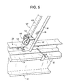
FIG. 5 is a detail view of a roller assembly for the sliding canopy member ofFIG. 4 ; -
FIG. 6 is a plan view of first and second adjustable canopy support members shown secured to the sliding canopy support member ofFIG. 4 ; -
FIG. 7 depicts an adjustment member of the first adjustable canopy support member ofFIG. 6 ; -
FIG. 8 depicts an adjustment element of the second adjustable canopy support member ofFIG. 6 ; -
FIG. 9 depicts an adjustable support bar provided to support a drive system of the turbomachine enclosure canopy system ofFIG. 3 ; -
FIG. 10 depicts a first driving member of the drive system ofFIG. 3 ; -
FIG. 11 depicts a second driving member of the drive system ofFIG. 3 ; -
FIG. 12 depicts a first driven member of the drive system ofFIG. 3 ; and -
FIG. 13 depicts a second driven member of the drive system ofFIG. 3 . - The detailed description explains embodiments of the invention, together with advantages and features, by way of example with reference to the drawings.
- With reference to
FIGS. 1-3 a turbomachine enclosure is indicated generally at 2.Turbomachine enclosure 2 includes first and secondopposing side walls 4 and 5 that are joined by third and fourthopposing side walls 6 and 7to form aturbomachine portion 9 having anupper opening 11. First and second side opposingside walls 4 and 5 include corresponding first and second support rails atupper opening 11.Upper opening 11 provides access toturbomachine portion 9 to allow for installation and removal of a turbomachine such as indicated at 16.Turbomachine enclosure 2 is shown to include a portable, retractable turbomachineenclosure canopy system 20 that supports acanopy 24 acrossupper opening 11. Turbomachineenclosure canopy system 20 is installed acrossupper opening 11 during maintenance operations that require installation and removal of turbomachine components, or a complete turbomachine, throughupper opening 11. During normal operation,turbomachine enclosure 2 includes a fixed cover (not shown) that extends acrossupper opening 11. - Turbomachine
enclosure canopy system 20 includes afirst rail member 28 secured tofirst support member 13 and asecond rail member 29 secured tosecond support member 14. First andsecond rail members second support members FIG. 4 . Turbomachineenclosure canopy system 20 includes a fixedcanopy support 32 having a first fixedcanopy support member 34 connected to a second fixedcanopy support member 35 through an adjustablecanopy support element 37. Adjustablecanopy support element 37 provides adjustment to allowfixed canopy support 32 to be fitted to turbomachine enclosures of various sizes. First fixedcanopy support member 35 includes awall support 39 that is fixedly mounted tofirst rail member 28. Second fixedcanopy support member 35 includes awall support 40 that is fixedly mounted tosecond rail member 29. First and second fixed canopy supportmembers upper opening 11. - Turbomachine
enclosure canopy system 20 also includes a plurality of sliding canopy supports 48-56 that are adjustably coupled to fixedcanopy support 32 by anextensible hinge member 57. As each sliding canopy support 48-56 includes similar structure, a description will follow referencing slidingcanopy support 48 with an understanding that the remaining canopy supports 49-56 are similarly formed. It should be understood however, the slidingcanopy support 56 is also provided with a plurality of canopy supports 60-63 that supportcanopy 24 acrossupper opening 11. Slidingcanopy support 48 includes a first slidingcanopy support member 70 operatively coupled to a secondcanopy support member 71 through first and second adjustablecanopy support members FIGS. 4-6 in describing second slidingcanopy support member 71 with an understanding that first slidingcanopy support member 70 is similarly formed. - Second sliding
canopy support member 71 includes acanopy support bar 86 and aspreader bar 88. Canopysupport bar 86 includes afirst end 91 that extends to asecond end 92 through anintermediate portion 93.First end 91 is linked to acanopy support 94 having a tie downelement 95 that provides an anchor point forcanopy 24. In a manner similar to that described above, canopy support 94positions canopy 24 across a portion ofupper opening 11.Spreader bar 88 includes afirst end section 98 that extends to asecond end section 99 through anintermediate section 100.First end section 98 is secured atfirst end 91 ofcanopy support bar 86. Astiffener 103 extends betweencanopy support bar 86 andspreader bar 88 connectingintermediate portion 93 withintermediate section 100. - In further accordance with the exemplary embodiment, first and second sliding
canopy support members wall support wall support 107 with an understanding that slidingwall support 106 is similarly formed. As best shown inFIG. 5 , slidingwall support 107 includes asupport member 120 having a first end portion 123 (FIG. 4 ) and asecond end portion 124.First end portion 123 is coupled to second slidingcanopy support member 71 atfirst end 91 ofcanopy support bar 86 andfirst end section 98 ofspreader bar 88. Slidingwall support 107 includes aroller assembly 130 arranged atsecond end portion 124.Roller assembly 130 includes afirst roller 133 that rests upon an upper surface (not separately labeled) ofsecond rail member 29 and asecond roller 135 that is positioned at a lower surface (also not separately labeled) ofsecond rail member 29.Second roller 135 is mounted to asupport plate 137 that is coupled atsecond end portion 124 ofsupport member 120. With this arrangement,roller assembly 130 facilitates transitioning slidingcanopy support 48 alongsecond rail member 29. - As best shown in
FIG. 6 ,canopy support bar 95 is adjustably connected to first adjustablecanopy support member 80 through anadjustment member 147 andspreader bar 88 is adjustable coupled to second adjustablecanopy support member 81 through anadjustment element 150. First adjustablecanopy support member 80 is also shown to include acoupler 151 and second adjustablecanopy support member 81 includes acouple 152 that serve to connect first slidingcanopy support member 70 to second slidingcanopy support member 71. As best shown inFIG. 7 ,second end 92 ofcanopy support bar 86 includes ainterior portion 154 that slidingly receives an end portion (not separately labeled) of first adjustablecanopy support member 80. With this arrangement,adjustment member 147 takes the form of aclamp member 159.Clamp member 159 includes a U-shaped bolt having first and second bolt ends 162 and 163. Aplate 165 is mounted across first and second bolt ends 162 and 163 and tightened ontosecond end 92 with a pair offasteners canopy support member 80 is in a desired position. As shown inFIG. 8 .Adjustment element 150 includes acollar 173 provided onsecond end section 99 ofspreader bar 88.Collar 173 includes aflange 175 that slidingly receives an end portion (not separately labeled) of second adjustablecanopy support member 81. Acompression member 180 is selectively biased against the end portion of second adjustablecanopy support member 81 to provide any desired adjustment. - In still further accordance with the exemplary embodiment, turbomachine
enclosure canopy system 20 includes a drive system 190 (FIG. 4 ) that shifts the sliding canopy supports along first andsecond rail members Drive system 190 is mounted to anadjustable support bar 194 that extends between first andsecond rail members FIG. 9 ,adjustable support bar 194 includes first andsecond bar members turbomachine enclosure 2. More specifically,adjustment support bar 194 includes first andsecond adjustment sections Adjustment section 198 includes a pair ofslots fasteners Fasteners second adjustment sections adjustable support bar 194 is in place. The particular type offasters -
Drive system 190 includes agear system 211 having a crankhandle 212.Gear system 211 is operatively connected to a first driving member 213 (FIG. 10 ) and a second driving member 214 (FIG. 11 ). First drivingmember 213 includes a first end 218 (FIG. 4 ) that extends to asecond end 219 that is supported at a first end (not separately labeled) offirst rail member 28.First end 218 is connected to gearsystem 211 andsecond end 219 includes a pulley that is rotated by first drivenmember 213. Similarly, second drivenmember 214 has a first end 227 (FIG. 4 ) that extends to asecond end 228 supported to a first end (not separately labeled) ofsecond rail member 29. First end 227of second drivenmember 214 is coupled togear system 211 andsecond end 228 of second drivenmember 214 is provided with apulley 229. - As shown in
FIGS. 12 and13 ,drive system 190 also includes afirst idler bar 237 mounted to a second, opposing end (not separately labeled) offirst rail member 28.Idler bar 237 includes apulley 238. Similarly, asecond idler bar 239 is mounted at a second, opposing end (also not separately labeled) ofsecond rail member 29.Second idler bar 29 includes apulley 240. Afirst cable 242 extends aboutpulleys second cable 246 extends aboutpulleys member 248 is connected betweencable 242 and a slidingcanopy support 56 and a second drivenmember 250 is connected betweencable 246 and slidingcanopy support 56. With this arrangement, rotation of crank handle 212 operatedgear system 211 causingcables second rail members canopy 24 coversupper opening 11. - At this point it should be understood that turbomachine enclosure canopy system in accordance with an exemplary embodiment provides a simple, cost effective and easily transportable cover that can be readily deployed across an upper opening of a turbomachine enclosure during maintenance periods. In this manner, service personnel can easily extend the turbomachine enclosure canopy system to cover the upper opening while working and retract the canopy when it is necessary to install and/or remove components through the upper opening.
- While the invention has been described in detail in connection with only a limited number of embodiments, it should be readily understood that the invention is not limited to such disclosed embodiments. Rather, the invention can be modified to incorporate any number of variations, alterations, substitutions or equivalent arrangements not heretofore described, but which are commensurate with the spirit and scope of the invention. Additionally, while various embodiments of the invention have been described, it is to be understood that aspects of the invention may include only some of the described embodiments. Accordingly, the invention is not to be seen as limited by the foregoing description, but is only limited by the scope of the appended claims.
- Various aspects and embodiments of the present invention are defined by the following numbered clauses:
- 1. A turbomachine enclosure canopy system comprising:
- a first rail member configured and disposed to be mounted to a first wall of a turbomachine enclosure, and a second rail member configured and disposed to be mounted to a second wall of the turbomachine enclosure;
- a first fixed canopy support member mounted to the first rail member, and a second fixed canopy support member mounted to the second rail member;
- a first sliding canopy support member seated on the first rail member, and a second sliding canopy support member seated on the second rail member; and
- an adjustable canopy support element moveably secured between the first and second fixed canopy support members to form a fixed canopy support, and an adjustable canopy support member moveably secured between the first and second sliding canopy support members to form a sliding canopy support.
- 2. The turbomachine enclosure canopy system according to
clause 1, further comprising: a canopy extending between the fixed canopy support and the sliding canopy support. - 3. The turbomachine enclosure canopy system according to any preceding clause, further comprising: a drive system coupled to the sliding canopy support, the drive system being configured and disposed to selectively shift the sliding canopy support relative to the fixed canopy support.
- 4. The turbomachine enclosure canopy system according to any preceding clause, wherein the drive system includes a driving member extending to one of the first and second rail members, and a driven member attached to one of the first and second sliding canopy support members.
- 5. The turbomachine enclosure canopy system according to any preceding clause, wherein the driven member includes a first driven member attached to the first sliding canopy support member and a second driven member attached to the second sliding canopy support member.
- 6. The turbomachine enclosure canopy system according to any preceding clause, further comprising: a sliding wall support operatively coupled to one of the first sliding canopy support member and the second sliding canopy support member.
- 7. The turbomachine enclosure canopy system according to any preceding clause, further comprising: a roller assembly operatively connected to the sliding wall support, the roller assembly including at least one roller
- 8. The turbomachine enclosure canopy system according to any preceding clause, wherein the at least one roller includes a first roller and a second roller.
- 9. The turbomachine enclosure canopy system according to any preceding clause, wherein the first roller is configured and disposed to ride along a first surface of one of the first and second rail members and the second roller is configured and disposed to ride along a second, opposing surface of the one of the first and second rail members.
- 10. The turbomachine enclosure canopy system according to any preceding clause, further comprising: a hinge member extending between the fixed canopy support member and the sliding canopy support.
- 11. A turbomachine enclosure comprising:
- a first side wall, a second side wall, a third side wall joining the first and second side walls at a first end and a fourth side wall joining the first and second side walls at a second end to establish a turbomachine portion having an opening;
- a turbomachine arranged within the turbomachine portion; and
- a turbomachine enclosure canopy system positioned across the opening, the turbomachine enclosure canopy system including:
- a first rail member mounted to the first wall, and a second rail member mounted to the second wall;
- a first fixed canopy support member mounted to the first rail member, and a second fixed canopy support member mounted to the second rail member;
- a first sliding canopy support member seated on the first rail member, and a second sliding canopy support member seated on the second rail member; and
- an adjustable canopy support element moveably secured between the first and second fixed canopy support members to form a fixed canopy support, and an adjustable canopy support member moveably secured between the first and second sliding canopy support members to form a sliding canopy support.
- 12. The turbomachine enclosure according to any preceding clause, further comprising: a canopy extending between the fixed canopy support and the sliding canopy support.
- 13. The turbomachine enclosure according to any preceding clause, further comprising: a drive system coupled to the turbomachine enclosure canopy system, the drive system being configured and disposed to selectively shift the sliding canopy support relative to the fixed canopy support.
- 14. The turbomachine enclosure according to any preceding clause, wherein the drive system includes a driving member extending between the first and second rail members, and a driven member attached to one of the first and second sliding canopy support members.
- 15. The turbomachine enclosure according to any preceding clause, wherein the driven member includes a first driven member attached to the first sliding canopy support member and a second driven member attached to the second sliding canopy support member.
- 16. The turbomachine enclosure according to any preceding clause, further comprising: a sliding wall support operatively coupled to one of the first sliding canopy support member and the second sliding canopy support member.
- 17. The turbomachine enclosure according to any preceding clause, further comprising: a roller assembly operatively connected to sliding wall support, the roller assembly including at least one roller
- 18. The turbomachine enclosure according to any preceding clause, wherein the at least one roller includes a first roller and a second roller.
- 19. The turbomachine enclosure according to any preceding clause, wherein the first roller is configured and disposed to ride along a first surface of one of the first and second rail members and the second roller is configured and disposed to ride along a second, opposing surface of the one of the first and second rail members.
- 20. The turbomachine enclosure according to any preceding clause, further comprising: a hinge member extending between the fixed canopy support member and the first sliding canopy support member.
Claims (15)
- A turbomachine enclosure canopy system (20) comprising:a first rail member (28) configured and disposed to be mounted to a first wall of a turbomachine enclosure, and a second rail member (29) configured and disposed to be mounted to a second wall of the turbomachine enclosure;a first fixed canopy support member (34) mounted to the first rail member (28), and a second fixed canopy support member (35) mounted to the second rail member (29);a first sliding canopy support member seated on the first rail member (28), and a second sliding canopy support member seated on the second rail member (29); andan adjustable canopy support element moveably secured between the first and second fixed canopy support members to form a fixed canopy support, and an adjustable canopy support member (48) moveably secured between the first and second sliding canopy support members (34, 35) to form a sliding canopy support.
- The turbomachine enclosure canopy system (20) according to claim 1, further comprising: a canopy extending between the fixed canopy support (34) and the sliding canopy support.
- The turbomachine enclosure canopy system (20) according to any preceding claim, further comprising: a drive system (190) coupled to the sliding canopy support, the drive system being configured and disposed to selectively shift the sliding canopy support relative to the fixed canopy support.
- The turbomachine enclosure canopy system (20) according to claim 3, wherein the drive system (190) includes a driving member extending to one of the first and second rail members, and a driven member attached to one of the first and second sliding canopy support members.
- The turbomachine enclosure canopy system (20) according to any preceding claim, wherein the driven member includes a first driven member attached to the first sliding canopy support member and a second driven member attached to the second sliding canopy support member.
- The turbomachine enclosure canopy system (20) according to any preceding claim, further comprising: a sliding wall support operatively coupled to one of the first sliding canopy support member and the second sliding canopy support member.
- The turbomachine enclosure canopy system (20) according to claim 6, further comprising: a roller assembly operatively connected to the sliding wall support, the roller assembly including at least one roller.
- The turbomachine enclosure canopy system (20) according to claim 7, wherein the at least one roller includes a first roller and a second roller.
- The turbomachine enclosure canopy system (20) according to claim 8, wherein the first roller is configured and disposed to ride along a first surface of one of the first and second rail members and the second roller is configured and disposed to ride along a second, opposing surface of the one of the first and second rail members.
- The turbomachine enclosure canopy system (20) according to any preceding claim, further comprising: a hinge member extending between the fixed canopy support system and the sliding canopy support.
- A turbomachine enclosure (20) comprising:a first side wall, a second side wall, a third side wall joining the first and second side walls at a first end and a fourth side wall joining the first and second side walls at a second end to establish a turbomachine portion having an opening;a turbomachine arranged within the turbomachine portion; anda turbomachine enclosure canopy system positioned across the opening, the turbomachine enclosure canopy system including:a first rail member (28) mounted to the first wall, and a second rail member (29) mounted to the second wall;a first fixed canopy support member mounted to the first rail member, and a second fixed canopy support member mounted to the second rail member;a first sliding canopy support member seated on the first rail member, and a second sliding canopy support member seated on the second rail member; andan adjustable canopy support element moveably secured between the first and second fixed canopy support members to form a fixed canopy support, and an adjustable canopy support member moveably secured between the first and second sliding canopy support members to form a sliding canopy support.
- The turbomachine enclosure (20) according to claim 11, further comprising: a canopy extending between the fixed canopy support and the sliding canopy support.
- The turbomachine enclosure (20) according to claim 11 or claim 12, further comprising: a drive system (190) coupled to the retractable canopy support system, the drive system being configured and disposed to selectively shift the sliding canopy support relative to the fixed canopy support.
- The turbomachine enclosure (20) according to claim 13, wherein the drive system includes a driving member extending between the first and second rail members, and a driven member attached to one of the first and second sliding canopy support members.
- The turbomachine enclosure (20) according to claim 14, wherein the driven member includes a first driven member attached to the first sliding canopy support member and a second driven member attached to the second sliding canopy support member.
Applications Claiming Priority (1)
| Application Number | Priority Date | Filing Date | Title |
|---|---|---|---|
| TR201107016 | 2011-07-15 |
Publications (1)
| Publication Number | Publication Date |
|---|---|
| EP2546475A2 true EP2546475A2 (en) | 2013-01-16 |
Family
ID=46603573
Family Applications (1)
| Application Number | Title | Priority Date | Filing Date |
|---|---|---|---|
| EP12176443A Withdrawn EP2546475A2 (en) | 2011-07-15 | 2012-07-13 | Turbomachine enclosure canopy system |
Country Status (3)
| Country | Link |
|---|---|
| US (1) | US20130014793A1 (en) |
| EP (1) | EP2546475A2 (en) |
| CN (1) | CN102877672A (en) |
Cited By (1)
| Publication number | Priority date | Publication date | Assignee | Title |
|---|---|---|---|---|
| EP3067523A1 (en) * | 2015-03-13 | 2016-09-14 | General Electric Company | Turbomachine exhaust frame lifting system and method |
Families Citing this family (8)
| Publication number | Priority date | Publication date | Assignee | Title |
|---|---|---|---|---|
| US9051725B2 (en) * | 2013-04-18 | 2015-06-09 | James Bert FARMER | Portable building |
| US9404281B1 (en) * | 2013-10-08 | 2016-08-02 | Adjustable Canopy, LLC | Adjustable canopy |
| US10124772B1 (en) | 2013-10-18 | 2018-11-13 | Todd James Hartman | Systems, methods, and apparatus for debris removal |
| CN103821394B (en) * | 2014-02-27 | 2015-11-25 | 常州第一建筑集团有限公司 | There is sand blasting room and the construction method thereof of movable roof |
| CN104100112B (en) * | 2014-06-26 | 2017-01-04 | 湖州旺能环保科技有限公司 | A kind of automatic deploying and retracting division box |
| ITUB20160847A1 (en) * | 2016-02-18 | 2017-08-18 | Nuovo Pignone Tecnologie Srl | COMPLETE TURBOMACCHINARY MODULE FOR LNG AND SIMILAR SYSTEMS |
| CN106760683B (en) * | 2016-12-09 | 2022-09-09 | 中国联合工程有限公司 | Automatic flexible folding canopy mechanism |
| US12409712B2 (en) * | 2022-03-11 | 2025-09-09 | Prodinteg LLC | Retractable cover assembly |
Family Cites Families (16)
| Publication number | Priority date | Publication date | Assignee | Title |
|---|---|---|---|---|
| US2603171A (en) * | 1947-03-26 | 1952-07-15 | H W Martin | Building structure |
| US3530623A (en) * | 1969-04-21 | 1970-09-29 | Fold Way Covers Ltd | Frame member for collapsible structure |
| US3729890A (en) * | 1971-04-22 | 1973-05-01 | Taiyo Kogyo Co Ltd | Shiftable pillar wheel supporting device |
| US4844109A (en) * | 1988-03-21 | 1989-07-04 | Pablo Navarro | Motor vehicle shelter |
| US5005896A (en) * | 1990-01-22 | 1991-04-09 | Li Cheng Chia | Retractable truck canopy frame |
| US5546972A (en) * | 1993-03-05 | 1996-08-20 | Wardell; Jacqueline R. | Kit cover systems for swimming pools, hot tubs and patios |
| CN2194830Y (en) * | 1993-09-03 | 1995-04-19 | 刘楚 | Activity car roof frame |
| US5524953A (en) * | 1994-06-03 | 1996-06-11 | Shaer; Jack E. | Contractable vehicle bed cover assembly with extendable closure |
| US5575607A (en) * | 1994-11-02 | 1996-11-19 | United Technologies Corporation | Jet engine transport vehicle lift system and a build cell |
| US6109283A (en) * | 1997-02-18 | 2000-08-29 | Burke; Robert L. | Retractable enclosure system |
| US6142554A (en) * | 1999-03-18 | 2000-11-07 | Truckhugger Tarp Systems, Inc. | Sliding bow dump truck cover |
| US6550491B1 (en) * | 1999-12-14 | 2003-04-22 | World Patent Development Corporation | Portable structure |
| US6431634B1 (en) * | 2001-01-16 | 2002-08-13 | Frederick Ananian | Collapsible truck shell assembly and accessories |
| CA2358377A1 (en) * | 2001-10-10 | 2003-04-10 | Donald Martin | Truck carrier |
| CN201291799Y (en) * | 2008-10-21 | 2009-08-19 | 张明方 | Liftable and expandable hood for wagon |
| US8910374B2 (en) * | 2012-10-04 | 2014-12-16 | General Electric Company | Service apparatus for turbomachine |
-
2012
- 2012-05-29 US US13/482,469 patent/US20130014793A1/en not_active Abandoned
- 2012-07-13 EP EP12176443A patent/EP2546475A2/en not_active Withdrawn
- 2012-07-16 CN CN2012102447805A patent/CN102877672A/en active Pending
Non-Patent Citations (1)
| Title |
|---|
| None |
Cited By (1)
| Publication number | Priority date | Publication date | Assignee | Title |
|---|---|---|---|---|
| EP3067523A1 (en) * | 2015-03-13 | 2016-09-14 | General Electric Company | Turbomachine exhaust frame lifting system and method |
Also Published As
| Publication number | Publication date |
|---|---|
| CN102877672A (en) | 2013-01-16 |
| US20130014793A1 (en) | 2013-01-17 |
Similar Documents
| Publication | Publication Date | Title |
|---|---|---|
| EP2546475A2 (en) | Turbomachine enclosure canopy system | |
| US9554482B2 (en) | Enclosure for a generator | |
| KR101038641B1 (en) | Maintenance system of wind turbine facility | |
| AU2002333780B2 (en) | Wind turbine with current conducting means, which are pre-assembled in the tower thereof | |
| EP2581336A1 (en) | Multifunctional platform of wind power generating unit and blade disassembling method | |
| EP2143937A2 (en) | Cable bridge for a wind turbine tower | |
| US8191316B2 (en) | Off-shore wind turbine and method of erecting a wind turbine tower | |
| US20150167342A1 (en) | Self-Climbing Telescopic Crane and Method for Mounting Pre-Fabricated Concrete Towers | |
| US20120279140A1 (en) | Automated covering system | |
| US20190309732A1 (en) | Rotor blade replacement system | |
| EP2412970A1 (en) | Nacelle for a wind turbine | |
| WO2008069818A1 (en) | Portable hub crane for wind turbine components | |
| US11512680B2 (en) | Lifting apparatus for an offshore wind turbine | |
| EP3478964B1 (en) | An assembly, an installation package and a method for use in installation of an installation unit in a wind turbine tower | |
| US20100078528A1 (en) | Cable tray for a wind turbine tower | |
| US20210388822A1 (en) | Extendable platforms for towers | |
| KR101324962B1 (en) | Wind blade, blade installation system, and method of blade installation using the same | |
| JP2009216087A (en) | Transport method for bulky equipment for wind power plant, and prefabricated equipment | |
| CA2320023C (en) | Circular clarifier with retractable cover | |
| KR20150002312U (en) | Sort cable out roller | |
| CN213731474U (en) | Device for mounting steam turbine | |
| JP4801385B2 (en) | Automatic sliding door drive unit and assembly thereof | |
| CN110336220A (en) | A kind of erecting cable vehicle and erection method | |
| CN107370302B (en) | Tool and method for laying down stator bore liner of generator | |
| KR20150076941A (en) | Apparatus for equipping a cable of an aerogenerator |
Legal Events
| Date | Code | Title | Description |
|---|---|---|---|
| PUAI | Public reference made under article 153(3) epc to a published international application that has entered the european phase |
Free format text: ORIGINAL CODE: 0009012 |
|
| AK | Designated contracting states |
Kind code of ref document: A2 Designated state(s): AL AT BE BG CH CY CZ DE DK EE ES FI FR GB GR HR HU IE IS IT LI LT LU LV MC MK MT NL NO PL PT RO RS SE SI SK SM TR |
|
| AX | Request for extension of the european patent |
Extension state: BA ME |
|
| STAA | Information on the status of an ep patent application or granted ep patent |
Free format text: STATUS: THE APPLICATION IS DEEMED TO BE WITHDRAWN |
|
| 18D | Application deemed to be withdrawn |
Effective date: 20150203 |