EP2546472A2 - Thermal management system for gas turbine engine - Google Patents
Thermal management system for gas turbine engine Download PDFInfo
- Publication number
- EP2546472A2 EP2546472A2 EP12162781A EP12162781A EP2546472A2 EP 2546472 A2 EP2546472 A2 EP 2546472A2 EP 12162781 A EP12162781 A EP 12162781A EP 12162781 A EP12162781 A EP 12162781A EP 2546472 A2 EP2546472 A2 EP 2546472A2
- Authority
- EP
- European Patent Office
- Prior art keywords
- heat exchanger
- recited
- gas turbine
- turbine engine
- valve
- Prior art date
- Legal status (The legal status is an assumption and is not a legal conclusion. Google has not performed a legal analysis and makes no representation as to the accuracy of the status listed.)
- Granted
Links
Images


Classifications
-
- F—MECHANICAL ENGINEERING; LIGHTING; HEATING; WEAPONS; BLASTING
- F02—COMBUSTION ENGINES; HOT-GAS OR COMBUSTION-PRODUCT ENGINE PLANTS
- F02C—GAS-TURBINE PLANTS; AIR INTAKES FOR JET-PROPULSION PLANTS; CONTROLLING FUEL SUPPLY IN AIR-BREATHING JET-PROPULSION PLANTS
- F02C7/00—Features, components parts, details or accessories, not provided for in, or of interest apart form groups F02C1/00 - F02C6/00; Air intakes for jet-propulsion plants
- F02C7/12—Cooling of plants
- F02C7/14—Cooling of plants of fluids in the plant, e.g. lubricant or fuel
-
- F—MECHANICAL ENGINEERING; LIGHTING; HEATING; WEAPONS; BLASTING
- F01—MACHINES OR ENGINES IN GENERAL; ENGINE PLANTS IN GENERAL; STEAM ENGINES
- F01D—NON-POSITIVE DISPLACEMENT MACHINES OR ENGINES, e.g. STEAM TURBINES
- F01D17/00—Regulating or controlling by varying flow
- F01D17/02—Arrangement of sensing elements
- F01D17/08—Arrangement of sensing elements responsive to condition of working-fluid, e.g. pressure
- F01D17/085—Arrangement of sensing elements responsive to condition of working-fluid, e.g. pressure to temperature
-
- F—MECHANICAL ENGINEERING; LIGHTING; HEATING; WEAPONS; BLASTING
- F01—MACHINES OR ENGINES IN GENERAL; ENGINE PLANTS IN GENERAL; STEAM ENGINES
- F01D—NON-POSITIVE DISPLACEMENT MACHINES OR ENGINES, e.g. STEAM TURBINES
- F01D17/00—Regulating or controlling by varying flow
- F01D17/10—Final actuators
- F01D17/12—Final actuators arranged in stator parts
- F01D17/14—Final actuators arranged in stator parts varying effective cross-sectional area of nozzles or guide conduits
- F01D17/148—Final actuators arranged in stator parts varying effective cross-sectional area of nozzles or guide conduits by means of rotatable members, e.g. butterfly valves
-
- F—MECHANICAL ENGINEERING; LIGHTING; HEATING; WEAPONS; BLASTING
- F01—MACHINES OR ENGINES IN GENERAL; ENGINE PLANTS IN GENERAL; STEAM ENGINES
- F01D—NON-POSITIVE DISPLACEMENT MACHINES OR ENGINES, e.g. STEAM TURBINES
- F01D25/00—Component parts, details, or accessories, not provided for in, or of interest apart from, other groups
- F01D25/08—Cooling; Heating; Heat-insulation
- F01D25/12—Cooling
-
- F—MECHANICAL ENGINEERING; LIGHTING; HEATING; WEAPONS; BLASTING
- F02—COMBUSTION ENGINES; HOT-GAS OR COMBUSTION-PRODUCT ENGINE PLANTS
- F02C—GAS-TURBINE PLANTS; AIR INTAKES FOR JET-PROPULSION PLANTS; CONTROLLING FUEL SUPPLY IN AIR-BREATHING JET-PROPULSION PLANTS
- F02C7/00—Features, components parts, details or accessories, not provided for in, or of interest apart form groups F02C1/00 - F02C6/00; Air intakes for jet-propulsion plants
- F02C7/12—Cooling of plants
- F02C7/16—Cooling of plants characterised by cooling medium
- F02C7/18—Cooling of plants characterised by cooling medium the medium being gaseous, e.g. air
- F02C7/185—Cooling means for reducing the temperature of the cooling air or gas
-
- F—MECHANICAL ENGINEERING; LIGHTING; HEATING; WEAPONS; BLASTING
- F02—COMBUSTION ENGINES; HOT-GAS OR COMBUSTION-PRODUCT ENGINE PLANTS
- F02C—GAS-TURBINE PLANTS; AIR INTAKES FOR JET-PROPULSION PLANTS; CONTROLLING FUEL SUPPLY IN AIR-BREATHING JET-PROPULSION PLANTS
- F02C9/00—Controlling gas-turbine plants; Controlling fuel supply in air- breathing jet-propulsion plants
- F02C9/16—Control of working fluid flow
- F02C9/18—Control of working fluid flow by bleeding, bypassing or acting on variable working fluid interconnections between turbines or compressors or their stages
-
- F—MECHANICAL ENGINEERING; LIGHTING; HEATING; WEAPONS; BLASTING
- F02—COMBUSTION ENGINES; HOT-GAS OR COMBUSTION-PRODUCT ENGINE PLANTS
- F02K—JET-PROPULSION PLANTS
- F02K3/00—Plants including a gas turbine driving a compressor or a ducted fan
- F02K3/02—Plants including a gas turbine driving a compressor or a ducted fan in which part of the working fluid by-passes the turbine and combustion chamber
- F02K3/04—Plants including a gas turbine driving a compressor or a ducted fan in which part of the working fluid by-passes the turbine and combustion chamber the plant including ducted fans, i.e. fans with high volume, low pressure outputs, for augmenting the jet thrust, e.g. of double-flow type
- F02K3/075—Plants including a gas turbine driving a compressor or a ducted fan in which part of the working fluid by-passes the turbine and combustion chamber the plant including ducted fans, i.e. fans with high volume, low pressure outputs, for augmenting the jet thrust, e.g. of double-flow type controlling flow ratio between flows
-
- F—MECHANICAL ENGINEERING; LIGHTING; HEATING; WEAPONS; BLASTING
- F05—INDEXING SCHEMES RELATING TO ENGINES OR PUMPS IN VARIOUS SUBCLASSES OF CLASSES F01-F04
- F05D—INDEXING SCHEME FOR ASPECTS RELATING TO NON-POSITIVE-DISPLACEMENT MACHINES OR ENGINES, GAS-TURBINES OR JET-PROPULSION PLANTS
- F05D2260/00—Function
- F05D2260/20—Heat transfer, e.g. cooling
- F05D2260/213—Heat transfer, e.g. cooling by the provision of a heat exchanger within the cooling circuit
-
- F—MECHANICAL ENGINEERING; LIGHTING; HEATING; WEAPONS; BLASTING
- F05—INDEXING SCHEMES RELATING TO ENGINES OR PUMPS IN VARIOUS SUBCLASSES OF CLASSES F01-F04
- F05D—INDEXING SCHEME FOR ASPECTS RELATING TO NON-POSITIVE-DISPLACEMENT MACHINES OR ENGINES, GAS-TURBINES OR JET-PROPULSION PLANTS
- F05D2260/00—Function
- F05D2260/20—Heat transfer, e.g. cooling
- F05D2260/232—Heat transfer, e.g. cooling characterized by the cooling medium
-
- F—MECHANICAL ENGINEERING; LIGHTING; HEATING; WEAPONS; BLASTING
- F05—INDEXING SCHEMES RELATING TO ENGINES OR PUMPS IN VARIOUS SUBCLASSES OF CLASSES F01-F04
- F05D—INDEXING SCHEME FOR ASPECTS RELATING TO NON-POSITIVE-DISPLACEMENT MACHINES OR ENGINES, GAS-TURBINES OR JET-PROPULSION PLANTS
- F05D2270/00—Control
- F05D2270/30—Control parameters, e.g. input parameters
- F05D2270/303—Temperature
-
- Y—GENERAL TAGGING OF NEW TECHNOLOGICAL DEVELOPMENTS; GENERAL TAGGING OF CROSS-SECTIONAL TECHNOLOGIES SPANNING OVER SEVERAL SECTIONS OF THE IPC; TECHNICAL SUBJECTS COVERED BY FORMER USPC CROSS-REFERENCE ART COLLECTIONS [XRACs] AND DIGESTS
- Y02—TECHNOLOGIES OR APPLICATIONS FOR MITIGATION OR ADAPTATION AGAINST CLIMATE CHANGE
- Y02T—CLIMATE CHANGE MITIGATION TECHNOLOGIES RELATED TO TRANSPORTATION
- Y02T50/00—Aeronautics or air transport
- Y02T50/60—Efficient propulsion technologies, e.g. for aircraft
Definitions
- the present disclosure relates to a gas turbine engine, and in particular, to a Thermal Management Systems (TMS) therefore.
- TMS Thermal Management Systems
- TMS Thermal Management Systems
- TMS Thermal Management Systems
- the heat of the lubricants in such systems has increased due to the use of larger electrical generators for increased electrical power production and geared turbofans with large fan-drive gearboxes.
- a duct is provided in a fan cowling through which a portion of the airstream is diverted, such that the lubricant is cooled by the ducted airstream.
- the airstream that is diverted through the duct system flows at least in part through an air-to-liquid heat exchanger which is sized to provide adequate cooling for the most extreme "corner point" conditions (hot day, idle, hot fuel).
- These heat exchangers may require relatively large cross-sectional area ducts that may result in additional drag.
- a base heat exchange that handles a significant portion of the mission points is combined with a so-called "peaker” heat exchanger to handle corner point conditions.
- One such TMS locates the "peaker” on the engine fan case which also requires oil lines and valves to be located along the fan case. This arrangement may require additional auxiliary inlets and outlets which may also result in additional drag.
- a thermal management system for a gas turbine engine includes a first heat exchange and a second heat exchanger in communication with a bypass flow through an inlet.
- a valve is operable to selectively communicate a portion of the bypass flow to either the first heat exchanger or the second heat exchanger through the inlet.
- a gas turbine engine includes an Environmental Control System (ECS) and an Air Oil Cooler (AOC) "peaker" in communication with a bypass flow through an inlet.
- ECS Environmental Control System
- AOC Air Oil Cooler
- a valve operable to selectively communicate a portion of the bypass flow to either the ECS pre-cooler or the AOC "peaker" through the inlet.
- a method of thermal management for a gas turbine engine includes selectively positioning a valve to communicate a bypass flow into either an Environmental Control System (ECS) pre-cooler or an Air Oil Cooler (AOC) "peaker" through a common inlet.
- ECS Environmental Control System
- AOC Air Oil Cooler
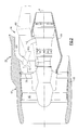
- FIG. 1 schematically illustrates a gas turbine engine 20.
- the gas turbine engine 20 is disclosed herein as a two-spool turbofan that generally incorporates a fan section 22, a compressor section 24, a combustor section 26 and a turbine section 28.
- Alternative engines might include an augmentor section (not shown) among other systems or features.
- the fan section 22 drives air along a bypass flowpath while the compressor section 24 drives air along a core flowpath for compression and communication into the combustor section 26 then expansion through the turbine section 28.
- FIG. 1 schematically illustrates a gas turbine engine 20.
- the gas turbine engine 20 is disclosed herein as a two-spool turbofan that generally incorporates a fan section 22, a compressor section 24, a combustor section 26 and a turbine section 28.
- Alternative engines might include an augmentor section (not shown) among other systems or features.
- the fan section 22 drives air along a bypass flowpath while the compressor section 24 drives air along a core flowpath for compression and communication into the combustor section 26
- the engine 20 generally includes a low speed spool 30 and a high speed spool 32 mounted for rotation about an engine central longitudinal axis A relative to an engine static structure 36 via several bearing systems 38. It should be understood that various bearing systems 38 at various locations may alternatively or additionally be provided.
- the low speed spool 30 generally includes an inner shaft 40 that interconnects a fan 42, a low pressure compressor 44 and a low pressure turbine 46.
- the inner shaft 40 is connected to the fan 42 through a geared architecture 48 to drive the fan 42 at a lower speed than the low speed spool 30.
- the high speed spool 32 includes an outer shaft 50 that interconnects a high pressure compressor 52 and high pressure turbine 54.
- a combustor 56 is arranged between the high pressure compressor 52 and the high pressure turbine 54.
- the inner shaft 40 and the outer shaft 50 are concentric and rotate about the engine central longitudinal axis A which is collinear with their longitudinal axes.
- the core airflow is compressed by the low pressure compressor 44 then the high pressure compressor 52, mixed with fuel and burned in the combustor 56, then expanded over the high pressure turbine 54 and low pressure turbine 46.
- the turbines 54, 46 rotationally drive the respective low speed spool 30 and high speed spool 32 in response to the expansion.
- the gas turbine engine 20 is mounted to an engine pylon structure 60 within an engine nacelle assembly 62 as is typical of an aircraft designed for subsonic operation.
- the nacelle assembly 62 generally includes a core nacelle 64 and a fan nacelle 66.
- a thermal management system (TMS) 68 is at least partially integrated into the nacelle assembly 62. It should be understood that although a particular component arrangement is disclosed in the illustrated embodiment, various pylon structures and nacelle assemblies will benefit herefrom.
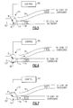
- the TMS 68 includes a first heat exchanger HX1 and a second heat exchanger HX2 which are both in communication with the bypass flow through a common inlet 70.
- the heat exchangers HX1, HX2 may be air/fluid, or air/air heat exchangers. Air/fluid heat exchangers are typically utilized to cool engine fluids to maintain low temperatures and air/air heat exchangers are typically utilized to cool high-temperature engine air for use in the aircraft cabin.
- the first heat exchanger HX1 is an Environmental Control System (ECS) pre-cooler and the second heat exchanger HX2 is an Air Oil Cooler (AOC) "peaker".
- ECS Environmental Control System
- AOC Air Oil Cooler
- the ECS pre-cooler which may be located within an engine strut fairing.
- the first heat exchanger HX1 and/or the second heat exchanger HX2 is suspended from a pylon 60' within an engine strut 36S ( Figures 3 and 4 ) if the engine pylon 60' mounts to the engine fan case 36F rather than the core case 36C.
- the FAMV 72 varies the bypass flow and thereby selectively controls the bypass air to the heat exchangers HX1, HX2.
- the exhaust flow from the heat exchangers HX1, HX2 may then be dumped into the core engine and/or overboard.
- the ECS pre-cooler system is typically placed under high demand during cold operation while the engine AOC "peaker” is typically utilized during hot operations which include “comer point” conditions such that the FAMV 72 selectively directs the bypass airflow as required in a mutually exclusive manner.
- a duct 74 downstream of the FAMV 72 thereby communicates a portion of bypass flow to either of the heat exchangers HX1, HX2.
- the thermal management system (TMS) 68 thereby minimizes the number of additionally auxiliary inlets and outlets required in the propulsion system to integrate the AOC "peaker". Additionally, the thermal management system (TMS) 68 does not require engine powered fans to drive the flow thru the AOC "peaker” to minimize or eliminate additional oil lines and electrical supply / control lines to the fan case.
- the FAMV 72 is in communication with the common inlet 70 to selectively direct the portion of the bypass flow to either of the heat exchangers HX1, HX2 through respective duct 76, 78 ( Figures 6, 7 ).
- the FAMV 72 includes a valve 80 which rotates about an axis of rotation B to selectively open the respective duct 76, 78 to inlet 70.
- the FAMV 72 provides an essentially infinite position to control bypass flow into the respective duct 76, 78. That is, the FAMV 72 is positioned by a control system 82 to, for example, partially open the respective duct 76, 78 and control the quantity of bypass flow thereto.
- the FAMV 72 may also be positioned to close both the respective ducts 76, 78 ( Figure 5 ).
Abstract
Description
- The present disclosure relates to a gas turbine engine, and in particular, to a Thermal Management Systems (TMS) therefore.
- Thermal Management Systems (TMS) include heat exchangers and associated equipment that utilize a pressurized lubricant. During usage, the lubricant receives thermal energy. The heat of the lubricants in such systems has increased due to the use of larger electrical generators for increased electrical power production and geared turbofans with large fan-drive gearboxes.
- In one TMS, a duct is provided in a fan cowling through which a portion of the airstream is diverted, such that the lubricant is cooled by the ducted airstream. The airstream that is diverted through the duct system flows at least in part through an air-to-liquid heat exchanger which is sized to provide adequate cooling for the most extreme "corner point" conditions (hot day, idle, hot fuel). These heat exchangers may require relatively large cross-sectional area ducts that may result in additional drag.
- Alternately, a base heat exchange that handles a significant portion of the mission points is combined with a so-called "peaker" heat exchanger to handle corner point conditions. One such TMS locates the "peaker" on the engine fan case which also requires oil lines and valves to be located along the fan case. This arrangement may require additional auxiliary inlets and outlets which may also result in additional drag.
- A thermal management system for a gas turbine engine according to an exemplary aspect of the present disclosure includes a first heat exchange and a second heat exchanger in communication with a bypass flow through an inlet. A valve is operable to selectively communicate a portion of the bypass flow to either the first heat exchanger or the second heat exchanger through the inlet.
- A gas turbine engine according to an exemplary aspect of the present disclosure includes an Environmental Control System (ECS) and an Air Oil Cooler (AOC) "peaker" in communication with a bypass flow through an inlet. A valve operable to selectively communicate a portion of the bypass flow to either the ECS pre-cooler or the AOC "peaker" through the inlet.
- A method of thermal management for a gas turbine engine according to an exemplary aspect of the present disclosure includes selectively positioning a valve to communicate a bypass flow into either an Environmental Control System (ECS) pre-cooler or an Air Oil Cooler (AOC) "peaker" through a common inlet.
- Various features will become apparent to those skilled in the art from the following detailed description of the disclosed non-limiting embodiment. The drawings that accompany the detailed description can be briefly described as follows:
-
Figure 1 is a general schematic cross-section of a gas turbine engine; -
Figure 2 is a side partial sectional view of one embodiment of a thermal management system; -
Figure 3 is a side partial phantom view of another non-limiting embodiment of a thermal management system; -
Figure 4 is a top view of the thermal management system ofFigure 3 ; -
Figure 5 is an expanded view of a valve arrangement for the thermal management system in first position; -
Figure 6 is an expanded view of the valve arrangement for the thermal management system in second position; and -
Figure 7 is an expanded view of the valve arrangement for the thermal management system in third position. -
Figure 1 schematically illustrates agas turbine engine 20. Thegas turbine engine 20 is disclosed herein as a two-spool turbofan that generally incorporates afan section 22, acompressor section 24, acombustor section 26 and aturbine section 28. Alternative engines might include an augmentor section (not shown) among other systems or features. Thefan section 22 drives air along a bypass flowpath while thecompressor section 24 drives air along a core flowpath for compression and communication into thecombustor section 26 then expansion through theturbine section 28. Although depicted as a turbofan gas turbine engine in the disclosed non-limiting embodiment, it should be understood that the concepts described herein are not limited to use with turbofans as the teachings may be applied to other types of turbine engines. - The
engine 20 generally includes alow speed spool 30 and ahigh speed spool 32 mounted for rotation about an engine central longitudinal axis A relative to an enginestatic structure 36 viaseveral bearing systems 38. It should be understood thatvarious bearing systems 38 at various locations may alternatively or additionally be provided. - The
low speed spool 30 generally includes aninner shaft 40 that interconnects afan 42, a low pressure compressor 44 and alow pressure turbine 46. Theinner shaft 40 is connected to thefan 42 through a gearedarchitecture 48 to drive thefan 42 at a lower speed than thelow speed spool 30. Thehigh speed spool 32 includes anouter shaft 50 that interconnects ahigh pressure compressor 52 andhigh pressure turbine 54. Acombustor 56 is arranged between thehigh pressure compressor 52 and thehigh pressure turbine 54. Theinner shaft 40 and theouter shaft 50 are concentric and rotate about the engine central longitudinal axis A which is collinear with their longitudinal axes. - The core airflow is compressed by the low pressure compressor 44 then the
high pressure compressor 52, mixed with fuel and burned in thecombustor 56, then expanded over thehigh pressure turbine 54 andlow pressure turbine 46. Theturbines low speed spool 30 andhigh speed spool 32 in response to the expansion. - With reference to
Figure 2 , thegas turbine engine 20 is mounted to anengine pylon structure 60 within anengine nacelle assembly 62 as is typical of an aircraft designed for subsonic operation. Thenacelle assembly 62 generally includes acore nacelle 64 and afan nacelle 66. A thermal management system (TMS) 68 is at least partially integrated into thenacelle assembly 62. It should be understood that although a particular component arrangement is disclosed in the illustrated embodiment, various pylon structures and nacelle assemblies will benefit herefrom. - The TMS 68 includes a first heat exchanger HX1 and a second heat exchanger HX2 which are both in communication with the bypass flow through a
common inlet 70. It should be understood that the heat exchangers HX1, HX2 may be air/fluid, or air/air heat exchangers. Air/fluid heat exchangers are typically utilized to cool engine fluids to maintain low temperatures and air/air heat exchangers are typically utilized to cool high-temperature engine air for use in the aircraft cabin. In one non-limiting embodiment, the first heat exchanger HX1 is an Environmental Control System (ECS) pre-cooler and the second heat exchanger HX2 is an Air Oil Cooler (AOC) "peaker". The ECS pre-cooler, which may be located within an engine strut fairing. In another disclosed, non-limiting embodiment, the first heat exchanger HX1 and/or the second heat exchanger HX2 is suspended from a pylon 60' within anengine strut 36S (Figures 3 and 4 ) if the engine pylon 60' mounts to theengine fan case 36F rather than thecore case 36C. - A "Fan Air Modulating Valve" (FAMV) 72 in communication with the
inlet 70 selectively directs a portion of the bypass flow to either of the heat exchangers HX1, HX2. TheFAMV 72 varies the bypass flow and thereby selectively controls the bypass air to the heat exchangers HX1, HX2. The exhaust flow from the heat exchangers HX1, HX2 may then be dumped into the core engine and/or overboard. - The ECS pre-cooler system is typically placed under high demand during cold operation while the engine AOC "peaker" is typically utilized during hot operations which include "comer point" conditions such that the FAMV 72 selectively directs the bypass airflow as required in a mutually exclusive manner. A
duct 74 downstream of theFAMV 72 thereby communicates a portion of bypass flow to either of the heat exchangers HX1, HX2. - The thermal management system (TMS) 68 thereby minimizes the number of additionally auxiliary inlets and outlets required in the propulsion system to integrate the AOC "peaker". Additionally, the thermal management system (TMS) 68 does not require engine powered fans to drive the flow thru the AOC "peaker" to minimize or eliminate additional oil lines and electrical supply / control lines to the fan case.
- With reference to
Figure 5 , theFAMV 72 is in communication with thecommon inlet 70 to selectively direct the portion of the bypass flow to either of the heat exchangers HX1, HX2 throughrespective duct 76, 78 (Figures 6, 7 ). In one non-limiting embodiment, theFAMV 72 includes avalve 80 which rotates about an axis of rotation B to selectively open therespective duct respective duct control system 82 to, for example, partially open therespective duct FAMV 72 may also be positioned to close both therespective ducts 76, 78 (Figure 5 ). - It should be understood that like reference numerals identify corresponding or similar elements throughout the several drawings. It should also be understood that although a particular component arrangement is disclosed in the illustrated embodiment, other arrangements will benefit herefrom.
- Although particular step sequences are shown, described, and claimed, it should be understood that steps may be performed in any order, separated or combined unless otherwise indicated and will still benefit from the present invention.
- The foregoing description is exemplary rather than defined by the limitations within. Various non-limiting embodiments are disclosed herein, however, one of ordinary skill in the art would recognize that various modifications and variations in light of the above teachings will fall within the scope of the appended claims. It is therefore to be understood that within the scope of the appended claims, the invention may be practiced other than as specifically described. For that reason, the appended claims should be studied to determine their true scope and content.
Claims (15)
- A thermal management system for a gas turbine engine comprising:an inlet;a first heat exchanger in communication with a bypass flow through said inlet;a second heat exchanger in communication with said bypass flow through said inlet; anda valve operable to selectively communicate said bypass flow to either said first heat exchanger or said second heat exchanger through said inlet.
- The system as recited in claim 1, wherein said first heat exchanger is an Environmental Control System (ECS) pre-cooler.
- The system as recited in claim 1, wherein said second heat exchanger is an Air Oil Cooler (AOC) "peaker".
- The system as recited in claim 1, wherein said first heat exchanger is an Environmental Control System (ECS) pre-cooler and said second heat exchanger is an Air Oil Cooler (AOC) "peaker".
- The system as recited in any preceding claim, wherein said valve is a three-position valve.
- The system as recited in any preceding claim, wherein said valve is rotatable about an axis of rotation.
- The gas turbine engine as recited in any preceding claim, wherein said valve is a Fan Air Modulating Valve" (FAMV) configured to vary said bypass flow.
- A gas turbine engine comprising the thermal management system of claim 1, or claim 5 or 6 when dependent on claim 1,
wherein the first heat exchanger is an Environmental Control System (ECS) pre-cooler, and said second heat exchanger is an Air Oil Cooler (AOC) "peaker" - The gas turbine engine as recited in claim 8, wherein said ECS pre-cooler is located within an engine strut.
- The gas turbine engine as recited in claim 8 or 9, wherein a control system is configured to position the valve so that said ECS pre-cooler is utilized during cold operations.
- The gas turbine engine as recited in claim 8, 9 or 10, wherein a control system is configured to position the valve so that said AOC "peaker" is utilized during hot operations.
- The gas turbine engine as recited in claim 8, 9, 10 or 11, wherein said bypass flow can be exhausted to a core flowpath downstream of said AOC "peaker".
- A method of thermal management for a gas turbine engine comprising:selectively positioning a valve to communicate a bypass flow into either an Environmental Control System (ECS) pre-cooler or an Air Oil Cooler (AOC) "peaker" through a common inlet.
- The method as recited in claim 13, further comprising:communicating the bypass airflow to the ECS pre-cooler during cold operations.
- The method as recited in claim 13 or 14, further comprising:communicating the bypass airflow to the AOC "peaker" during hot operations.
Applications Claiming Priority (1)
| Application Number | Priority Date | Filing Date | Title |
|---|---|---|---|
| US13/096,130 US8904753B2 (en) | 2011-04-28 | 2011-04-28 | Thermal management system for gas turbine engine |
Publications (3)
| Publication Number | Publication Date |
|---|---|
| EP2546472A2 true EP2546472A2 (en) | 2013-01-16 |
| EP2546472A3 EP2546472A3 (en) | 2015-12-23 |
| EP2546472B1 EP2546472B1 (en) | 2017-01-04 |
Family
ID=45954465
Family Applications (1)
| Application Number | Title | Priority Date | Filing Date |
|---|---|---|---|
| EP12162781.4A Active EP2546472B1 (en) | 2011-04-28 | 2012-03-30 | Thermal management system for gas turbine engine |
Country Status (2)
| Country | Link |
|---|---|
| US (2) | US8904753B2 (en) |
| EP (1) | EP2546472B1 (en) |
Cited By (2)
| Publication number | Priority date | Publication date | Assignee | Title |
|---|---|---|---|---|
| EP3179086A1 (en) * | 2015-12-07 | 2017-06-14 | General Electric Company | Gas turbine engine fluid cooling systems and methods of operating the same |
| EP3106646B1 (en) | 2015-06-16 | 2020-12-16 | Raytheon Technologies Corporation | Turbofan engine with a cooled cooling air system and a corresponding method |
Families Citing this family (34)
| Publication number | Priority date | Publication date | Assignee | Title |
|---|---|---|---|---|
| US9353684B2 (en) * | 2009-12-11 | 2016-05-31 | Northrop Grumman Systems Corporation | Aircraft engine airflow modulation apparatus and method for engine bay cooling and cycle flow matching |
| US8978352B2 (en) * | 2011-10-21 | 2015-03-17 | United Technologies Corporation | Apparatus and method for operating a gas turbine engine during windmilling |
| US8978351B2 (en) * | 2011-10-21 | 2015-03-17 | United Technologies Corporation | Integrated thermal management system and environmental control system for a gas turbine engine |
| US9200569B2 (en) * | 2011-10-21 | 2015-12-01 | United Technologies Corporation | Compartment cooling for a gas turbine engine |
| US9267434B2 (en) * | 2012-01-29 | 2016-02-23 | United Technologies Corporation | Heat exchanger |
| US9394803B2 (en) * | 2012-03-14 | 2016-07-19 | United Technologies Corporation | Bypass air-pump system within the core engine to provide air for an environmental control system in a gas turbine engine |
| US9151224B2 (en) * | 2012-03-14 | 2015-10-06 | United Technologies Corporation | Constant-speed pump system for engine thermal management system AOC reduction and environmental control system loss elimination |
| US9163562B2 (en) * | 2012-03-14 | 2015-10-20 | United Technologies Corporation | Constant speed pump system for engine ECS loss elimination |
| US20130283762A1 (en) * | 2012-04-27 | 2013-10-31 | General Electric Company | Rotary vane actuator operated air valves |
| US20140130479A1 (en) * | 2012-11-14 | 2014-05-15 | United Technologies Corporation | Gas Turbine Engine With Mount for Low Pressure Turbine Section |
| US9206912B2 (en) * | 2013-01-23 | 2015-12-08 | The Boeing Company | Dual door fan air modulating valve |
| CN105026727A (en) * | 2013-03-06 | 2015-11-04 | 庞巴迪公司 | Apparatus for protecting aircraft components against foreign object damage |
| EP2971739B1 (en) * | 2013-03-14 | 2020-03-18 | Rolls-Royce North American Technologies, Inc. | Gas turbine engine flow duct having two rows of integrated heat exchangers |
| WO2014151356A1 (en) * | 2013-03-15 | 2014-09-25 | United Technologies Corporation | Geared architecture turbofan engine thermal management system and method |
| GB201408415D0 (en) * | 2014-05-13 | 2014-06-25 | Rolls Royce Plc | Bifurcation fairing |
| US9341119B2 (en) * | 2014-07-03 | 2016-05-17 | Hamilton Sundstrand Corporation | Cooling air system for aircraft turbine engine |
| US10907500B2 (en) * | 2015-02-06 | 2021-02-02 | Raytheon Technologies Corporation | Heat exchanger system with spatially varied additively manufactured heat transfer surfaces |
| GB201504010D0 (en) * | 2015-03-10 | 2015-04-22 | Rolls Royce Plc | Gas bleed arrangement |
| US11434822B2 (en) * | 2015-06-19 | 2022-09-06 | Raytheon Technologies Corporation | Inverse modulation of secondary bleed |
| US10260419B2 (en) | 2015-07-31 | 2019-04-16 | General Electric Company | Cooling system |
| US10513981B2 (en) * | 2016-01-21 | 2019-12-24 | Rolls-Royce North American Technologies Inc. | Heat exchanger assembly for a gas turbine engine propulsion system |
| US10563585B2 (en) | 2016-03-02 | 2020-02-18 | United Technologies Corporation | Heat exchanger for gas turbine engine |
| US10208676B2 (en) | 2016-03-29 | 2019-02-19 | General Electric Company | Gas turbine engine dual sealing cylindrical variable bleed valve |
| GB201608523D0 (en) * | 2016-05-16 | 2016-06-29 | Rolls Royce Plc | Heat sink |
| US11203437B2 (en) | 2016-06-30 | 2021-12-21 | Bombardier Inc. | Assembly and method for conditioning engine-heated air onboard an aircraft |
| US10544717B2 (en) | 2016-09-07 | 2020-01-28 | Pratt & Whitney Canada Corp. | Shared oil system arrangement for an engine component and a generator |
| US10989071B2 (en) * | 2018-08-03 | 2021-04-27 | Meggitt (Uk) Limited | High efficiency ducted heat exchanger systems |
| FR3095005B1 (en) * | 2019-04-09 | 2021-03-19 | Safran Aircraft Engines | TURBOMACHINE FOR AN AIRCRAFT |
| US10927761B2 (en) | 2019-04-17 | 2021-02-23 | General Electric Company | Refreshing heat management fluid in a turbomachine |
| US11448131B2 (en) * | 2019-04-17 | 2022-09-20 | General Electric Company | Fluid exchange apparatuses and methods of exchanging fluids between streams |
| CN110439692A (en) * | 2019-08-19 | 2019-11-12 | 中国商用飞机有限责任公司 | Engine blower air inlet device |
| US11536205B2 (en) | 2020-03-31 | 2022-12-27 | Rolls-Royce Plc | Gas turbine engine operating schedules for optimizing ceramic matrix composite component life |
| US11512639B2 (en) * | 2021-01-26 | 2022-11-29 | General Electric Company | Heat transfer system |
| US11897624B2 (en) | 2021-02-01 | 2024-02-13 | General Electric Company | Method for thermal management for an aircraft propulsion system using a flow of compressed fluid extracted from a compressor section |
Family Cites Families (15)
| Publication number | Priority date | Publication date | Assignee | Title |
|---|---|---|---|---|
| GB2241742B (en) * | 1988-03-23 | 1992-06-03 | Rolls Royce Plc | Minimising the effects of icing in the intakes of aerospace propulsors. |
| GB8907788D0 (en) * | 1989-04-06 | 1989-05-17 | Rolls Royce Plc | Management of heat generated by aircraft gas turbine installations |
| US5241814A (en) | 1989-04-06 | 1993-09-07 | Rolls-Royce Plc | Management of heat generated by aircraft gas turbine installations |
| US5123242A (en) * | 1990-07-30 | 1992-06-23 | General Electric Company | Precooling heat exchange arrangement integral with mounting structure fairing of gas turbine engine |
| GB9027782D0 (en) | 1990-12-21 | 1991-02-13 | Rolls Royce Plc | Heat exchanger apparatus |
| US5918458A (en) * | 1997-02-14 | 1999-07-06 | General Electric Company | System and method of providing clean filtered cooling air to a hot portion of a gas turbine engine |
| JP4005025B2 (en) * | 2001-11-02 | 2007-11-07 | ボーグワーナー・インコーポレーテッド | Controlled turbocharger with integrated bypass |
| GB0318400D0 (en) | 2003-08-06 | 2003-09-10 | Rolls Royce Plc | A fluid system |
| US7454894B2 (en) | 2004-12-07 | 2008-11-25 | United Technologies Corporation | Supplemental oil cooler airflow for gas turbine engine |
| FR2891313A1 (en) | 2005-09-26 | 2007-03-30 | Airbus France Sas | DOUBLE FLOW TURBOMOTEUR HAVING A PRE-COOLER |
| US20080028763A1 (en) | 2006-08-03 | 2008-02-07 | United Technologies Corporation | Thermal management system with thrust recovery for a gas turbine engine fan nacelle assembly |
| US9234481B2 (en) * | 2008-01-25 | 2016-01-12 | United Technologies Corporation | Shared flow thermal management system |
| US20090313999A1 (en) * | 2008-05-13 | 2009-12-24 | Scott Hunter | Method and apparatus for controlling fuel in a gas turbine engine |
| US8307662B2 (en) * | 2009-10-15 | 2012-11-13 | General Electric Company | Gas turbine engine temperature modulated cooling flow |
| US8257024B1 (en) * | 2012-01-27 | 2012-09-04 | United Technologies Corporation | Geared turbomachine fluid delivery system |
-
2011
- 2011-04-28 US US13/096,130 patent/US8904753B2/en not_active Expired - Fee Related
-
2012
- 2012-03-30 EP EP12162781.4A patent/EP2546472B1/en active Active
-
2014
- 2014-11-05 US US14/533,611 patent/US9863318B2/en active Active
Non-Patent Citations (1)
| Title |
|---|
| None |
Cited By (4)
| Publication number | Priority date | Publication date | Assignee | Title |
|---|---|---|---|---|
| EP3106646B1 (en) | 2015-06-16 | 2020-12-16 | Raytheon Technologies Corporation | Turbofan engine with a cooled cooling air system and a corresponding method |
| EP3179086A1 (en) * | 2015-12-07 | 2017-06-14 | General Electric Company | Gas turbine engine fluid cooling systems and methods of operating the same |
| US10323540B2 (en) | 2015-12-07 | 2019-06-18 | General Electric Company | Gas turbine engine fluid cooling systems and methods of assembling the same |
| US11035250B2 (en) | 2015-12-07 | 2021-06-15 | General Electric Company | Gas turbine engine fluid cooling systems and methods of assembling the same |
Also Published As
| Publication number | Publication date |
|---|---|
| US9863318B2 (en) | 2018-01-09 |
| EP2546472B1 (en) | 2017-01-04 |
| US20150052907A1 (en) | 2015-02-26 |
| EP2546472A3 (en) | 2015-12-23 |
| US8904753B2 (en) | 2014-12-09 |
| US20120272658A1 (en) | 2012-11-01 |
Similar Documents
| Publication | Publication Date | Title |
|---|---|---|
| US9863318B2 (en) | Thermal management system for gas turbine engine | |
| US9038397B2 (en) | Gas turbine engine thermal management system | |
| CN106988887B (en) | Gas turbine engine fluid cooling system and method of assembling same | |
| EP2085599B1 (en) | Shared flow thermal management system | |
| US10443436B2 (en) | Modular annular heat exchanger | |
| EP0736138B1 (en) | Increased cooling of turbine engine oil | |
| EP2615276B1 (en) | Air recovery system for precooler heat-exchanger and corresponding method | |
| EP3428427B1 (en) | Gas turbine engine with air-oil cooler oil tank | |
| US20080028763A1 (en) | Thermal management system with thrust recovery for a gas turbine engine fan nacelle assembly | |
| EP2584168A2 (en) | Integrated thermal system for a gas turbine engine | |
| US8495857B2 (en) | Gas turbine engine thermal management system | |
| EP2085600B1 (en) | Thermal management system integrated pylon | |
| EP3121417B1 (en) | Integral oiltank heat exchanger | |
| US20150361891A1 (en) | Air-Oil Heat Exchangers with Minimum Bypass Flow Pressure Loss | |
| EP3733520B1 (en) | Thermal management system with cooling turbine and generator | |
| CN115614156A (en) | Method of managing thermal energy in a propulsion system | |
| US20200256252A1 (en) | Hydraulically Driven Local Pump | |
| US11788470B2 (en) | Gas turbine engine thermal management | |
| US11105221B2 (en) | Geared architecture turbofan engine thermal management system and method | |
| EP2971646B1 (en) | Gas turbine engine thermal management system |
Legal Events
| Date | Code | Title | Description |
|---|---|---|---|
| PUAI | Public reference made under article 153(3) epc to a published international application that has entered the european phase |
Free format text: ORIGINAL CODE: 0009012 |
|
| AK | Designated contracting states |
Kind code of ref document: A2 Designated state(s): AL AT BE BG CH CY CZ DE DK EE ES FI FR GB GR HR HU IE IS IT LI LT LU LV MC MK MT NL NO PL PT RO RS SE SI SK SM TR |
|
| AX | Request for extension of the european patent |
Extension state: BA ME |
|
| PUAL | Search report despatched |
Free format text: ORIGINAL CODE: 0009013 |
|
| AK | Designated contracting states |
Kind code of ref document: A3 Designated state(s): AL AT BE BG CH CY CZ DE DK EE ES FI FR GB GR HR HU IE IS IT LI LT LU LV MC MK MT NL NO PL PT RO RS SE SI SK SM TR |
|
| AX | Request for extension of the european patent |
Extension state: BA ME |
|
| RIC1 | Information provided on ipc code assigned before grant |
Ipc: F01D 17/08 20060101ALI20151116BHEP Ipc: F01D 25/12 20060101ALI20151116BHEP Ipc: F02C 7/18 20060101ALI20151116BHEP Ipc: F02C 7/14 20060101AFI20151116BHEP |
|
| REG | Reference to a national code |
Ref country code: DE Ref legal event code: R079 Ref document number: 602012027287 Country of ref document: DE Free format text: PREVIOUS MAIN CLASS: F01D0017080000 Ipc: F02C0007140000 |
|
| 17P | Request for examination filed |
Effective date: 20160616 |
|
| RBV | Designated contracting states (corrected) |
Designated state(s): AL AT BE BG CH CY CZ DE DK EE ES FI FR GB GR HR HU IE IS IT LI LT LU LV MC MK MT NL NO PL PT RO RS SE SI SK SM TR |
|
| GRAP | Despatch of communication of intention to grant a patent |
Free format text: ORIGINAL CODE: EPIDOSNIGR1 |
|
| RIC1 | Information provided on ipc code assigned before grant |
Ipc: F01D 25/12 20060101ALI20160705BHEP Ipc: F02C 7/18 20060101ALI20160705BHEP Ipc: F01D 17/14 20060101ALI20160705BHEP Ipc: F02C 7/14 20060101AFI20160705BHEP Ipc: F01D 17/08 20060101ALI20160705BHEP |
|
| INTG | Intention to grant announced |
Effective date: 20160809 |
|
| GRAJ | Information related to disapproval of communication of intention to grant by the applicant or resumption of examination proceedings by the epo deleted |
Free format text: ORIGINAL CODE: EPIDOSDIGR1 |
|
| RAP1 | Party data changed (applicant data changed or rights of an application transferred) |
Owner name: UNITED TECHNOLOGIES CORPORATION |
|
| GRAR | Information related to intention to grant a patent recorded |
Free format text: ORIGINAL CODE: EPIDOSNIGR71 |
|
| GRAS | Grant fee paid |
Free format text: ORIGINAL CODE: EPIDOSNIGR3 |
|
| INTC | Intention to grant announced (deleted) | ||
| GRAA | (expected) grant |
Free format text: ORIGINAL CODE: 0009210 |
|
| INTG | Intention to grant announced |
Effective date: 20161124 |
|
| AK | Designated contracting states |
Kind code of ref document: B1 Designated state(s): AL AT BE BG CH CY CZ DE DK EE ES FI FR GB GR HR HU IE IS IT LI LT LU LV MC MK MT NL NO PL PT RO RS SE SI SK SM TR |
|
| REG | Reference to a national code |
Ref country code: GB Ref legal event code: FG4D |
|
| REG | Reference to a national code |
Ref country code: CH Ref legal event code: EP |
|
| REG | Reference to a national code |
Ref country code: AT Ref legal event code: REF Ref document number: 859464 Country of ref document: AT Kind code of ref document: T Effective date: 20170115 |
|
| REG | Reference to a national code |
Ref country code: IE Ref legal event code: FG4D |
|
| REG | Reference to a national code |
Ref country code: DE Ref legal event code: R096 Ref document number: 602012027287 Country of ref document: DE |
|
| REG | Reference to a national code |
Ref country code: FR Ref legal event code: PLFP Year of fee payment: 6 |
|
| REG | Reference to a national code |
Ref country code: LT Ref legal event code: MG4D Ref country code: NL Ref legal event code: MP Effective date: 20170104 |
|
| REG | Reference to a national code |
Ref country code: AT Ref legal event code: MK05 Ref document number: 859464 Country of ref document: AT Kind code of ref document: T Effective date: 20170104 |
|
| PG25 | Lapsed in a contracting state [announced via postgrant information from national office to epo] |
Ref country code: NL Free format text: LAPSE BECAUSE OF FAILURE TO SUBMIT A TRANSLATION OF THE DESCRIPTION OR TO PAY THE FEE WITHIN THE PRESCRIBED TIME-LIMIT Effective date: 20170104 |
|
| REG | Reference to a national code |
Ref country code: DE Ref legal event code: R082 Ref document number: 602012027287 Country of ref document: DE Representative=s name: SCHMITT-NILSON SCHRAUD WAIBEL WOHLFROM PATENTA, DE |
|
| PG25 | Lapsed in a contracting state [announced via postgrant information from national office to epo] |
Ref country code: LT Free format text: LAPSE BECAUSE OF FAILURE TO SUBMIT A TRANSLATION OF THE DESCRIPTION OR TO PAY THE FEE WITHIN THE PRESCRIBED TIME-LIMIT Effective date: 20170104 Ref country code: NO Free format text: LAPSE BECAUSE OF FAILURE TO SUBMIT A TRANSLATION OF THE DESCRIPTION OR TO PAY THE FEE WITHIN THE PRESCRIBED TIME-LIMIT Effective date: 20170404 Ref country code: GR Free format text: LAPSE BECAUSE OF FAILURE TO SUBMIT A TRANSLATION OF THE DESCRIPTION OR TO PAY THE FEE WITHIN THE PRESCRIBED TIME-LIMIT Effective date: 20170405 Ref country code: HR Free format text: LAPSE BECAUSE OF FAILURE TO SUBMIT A TRANSLATION OF THE DESCRIPTION OR TO PAY THE FEE WITHIN THE PRESCRIBED TIME-LIMIT Effective date: 20170104 Ref country code: FI Free format text: LAPSE BECAUSE OF FAILURE TO SUBMIT A TRANSLATION OF THE DESCRIPTION OR TO PAY THE FEE WITHIN THE PRESCRIBED TIME-LIMIT Effective date: 20170104 Ref country code: IS Free format text: LAPSE BECAUSE OF FAILURE TO SUBMIT A TRANSLATION OF THE DESCRIPTION OR TO PAY THE FEE WITHIN THE PRESCRIBED TIME-LIMIT Effective date: 20170504 |
|
| PG25 | Lapsed in a contracting state [announced via postgrant information from national office to epo] |
Ref country code: RS Free format text: LAPSE BECAUSE OF FAILURE TO SUBMIT A TRANSLATION OF THE DESCRIPTION OR TO PAY THE FEE WITHIN THE PRESCRIBED TIME-LIMIT Effective date: 20170104 Ref country code: LV Free format text: LAPSE BECAUSE OF FAILURE TO SUBMIT A TRANSLATION OF THE DESCRIPTION OR TO PAY THE FEE WITHIN THE PRESCRIBED TIME-LIMIT Effective date: 20170104 Ref country code: PT Free format text: LAPSE BECAUSE OF FAILURE TO SUBMIT A TRANSLATION OF THE DESCRIPTION OR TO PAY THE FEE WITHIN THE PRESCRIBED TIME-LIMIT Effective date: 20170504 Ref country code: PL Free format text: LAPSE BECAUSE OF FAILURE TO SUBMIT A TRANSLATION OF THE DESCRIPTION OR TO PAY THE FEE WITHIN THE PRESCRIBED TIME-LIMIT Effective date: 20170104 Ref country code: AT Free format text: LAPSE BECAUSE OF FAILURE TO SUBMIT A TRANSLATION OF THE DESCRIPTION OR TO PAY THE FEE WITHIN THE PRESCRIBED TIME-LIMIT Effective date: 20170104 Ref country code: ES Free format text: LAPSE BECAUSE OF FAILURE TO SUBMIT A TRANSLATION OF THE DESCRIPTION OR TO PAY THE FEE WITHIN THE PRESCRIBED TIME-LIMIT Effective date: 20170104 Ref country code: BG Free format text: LAPSE BECAUSE OF FAILURE TO SUBMIT A TRANSLATION OF THE DESCRIPTION OR TO PAY THE FEE WITHIN THE PRESCRIBED TIME-LIMIT Effective date: 20170404 Ref country code: SE Free format text: LAPSE BECAUSE OF FAILURE TO SUBMIT A TRANSLATION OF THE DESCRIPTION OR TO PAY THE FEE WITHIN THE PRESCRIBED TIME-LIMIT Effective date: 20170104 |
|
| REG | Reference to a national code |
Ref country code: DE Ref legal event code: R097 Ref document number: 602012027287 Country of ref document: DE |
|
| PG25 | Lapsed in a contracting state [announced via postgrant information from national office to epo] |
Ref country code: CZ Free format text: LAPSE BECAUSE OF FAILURE TO SUBMIT A TRANSLATION OF THE DESCRIPTION OR TO PAY THE FEE WITHIN THE PRESCRIBED TIME-LIMIT Effective date: 20170104 Ref country code: IT Free format text: LAPSE BECAUSE OF FAILURE TO SUBMIT A TRANSLATION OF THE DESCRIPTION OR TO PAY THE FEE WITHIN THE PRESCRIBED TIME-LIMIT Effective date: 20170104 Ref country code: EE Free format text: LAPSE BECAUSE OF FAILURE TO SUBMIT A TRANSLATION OF THE DESCRIPTION OR TO PAY THE FEE WITHIN THE PRESCRIBED TIME-LIMIT Effective date: 20170104 Ref country code: SK Free format text: LAPSE BECAUSE OF FAILURE TO SUBMIT A TRANSLATION OF THE DESCRIPTION OR TO PAY THE FEE WITHIN THE PRESCRIBED TIME-LIMIT Effective date: 20170104 Ref country code: RO Free format text: LAPSE BECAUSE OF FAILURE TO SUBMIT A TRANSLATION OF THE DESCRIPTION OR TO PAY THE FEE WITHIN THE PRESCRIBED TIME-LIMIT Effective date: 20170104 |
|
| REG | Reference to a national code |
Ref country code: CH Ref legal event code: PL |
|
| PLBE | No opposition filed within time limit |
Free format text: ORIGINAL CODE: 0009261 |
|
| STAA | Information on the status of an ep patent application or granted ep patent |
Free format text: STATUS: NO OPPOSITION FILED WITHIN TIME LIMIT |
|
| PG25 | Lapsed in a contracting state [announced via postgrant information from national office to epo] |
Ref country code: MC Free format text: LAPSE BECAUSE OF FAILURE TO SUBMIT A TRANSLATION OF THE DESCRIPTION OR TO PAY THE FEE WITHIN THE PRESCRIBED TIME-LIMIT Effective date: 20170104 Ref country code: SM Free format text: LAPSE BECAUSE OF FAILURE TO SUBMIT A TRANSLATION OF THE DESCRIPTION OR TO PAY THE FEE WITHIN THE PRESCRIBED TIME-LIMIT Effective date: 20170104 Ref country code: DK Free format text: LAPSE BECAUSE OF FAILURE TO SUBMIT A TRANSLATION OF THE DESCRIPTION OR TO PAY THE FEE WITHIN THE PRESCRIBED TIME-LIMIT Effective date: 20170104 |
|
| 26N | No opposition filed |
Effective date: 20171005 |
|
| REG | Reference to a national code |
Ref country code: IE Ref legal event code: MM4A |
|
| PG25 | Lapsed in a contracting state [announced via postgrant information from national office to epo] |
Ref country code: LU Free format text: LAPSE BECAUSE OF NON-PAYMENT OF DUE FEES Effective date: 20170330 |
|
| REG | Reference to a national code |
Ref country code: FR Ref legal event code: PLFP Year of fee payment: 7 |
|
| PG25 | Lapsed in a contracting state [announced via postgrant information from national office to epo] |
Ref country code: IE Free format text: LAPSE BECAUSE OF NON-PAYMENT OF DUE FEES Effective date: 20170330 Ref country code: LI Free format text: LAPSE BECAUSE OF NON-PAYMENT OF DUE FEES Effective date: 20170331 Ref country code: SI Free format text: LAPSE BECAUSE OF FAILURE TO SUBMIT A TRANSLATION OF THE DESCRIPTION OR TO PAY THE FEE WITHIN THE PRESCRIBED TIME-LIMIT Effective date: 20170104 Ref country code: CH Free format text: LAPSE BECAUSE OF NON-PAYMENT OF DUE FEES Effective date: 20170331 |
|
| REG | Reference to a national code |
Ref country code: BE Ref legal event code: MM Effective date: 20170331 |
|
| PG25 | Lapsed in a contracting state [announced via postgrant information from national office to epo] |
Ref country code: BE Free format text: LAPSE BECAUSE OF NON-PAYMENT OF DUE FEES Effective date: 20170331 |
|
| PG25 | Lapsed in a contracting state [announced via postgrant information from national office to epo] |
Ref country code: MT Free format text: LAPSE BECAUSE OF NON-PAYMENT OF DUE FEES Effective date: 20170330 |
|
| PG25 | Lapsed in a contracting state [announced via postgrant information from national office to epo] |
Ref country code: HU Free format text: LAPSE BECAUSE OF FAILURE TO SUBMIT A TRANSLATION OF THE DESCRIPTION OR TO PAY THE FEE WITHIN THE PRESCRIBED TIME-LIMIT; INVALID AB INITIO Effective date: 20120330 |
|
| PG25 | Lapsed in a contracting state [announced via postgrant information from national office to epo] |
Ref country code: CY Free format text: LAPSE BECAUSE OF NON-PAYMENT OF DUE FEES Effective date: 20170104 |
|
| PG25 | Lapsed in a contracting state [announced via postgrant information from national office to epo] |
Ref country code: MK Free format text: LAPSE BECAUSE OF FAILURE TO SUBMIT A TRANSLATION OF THE DESCRIPTION OR TO PAY THE FEE WITHIN THE PRESCRIBED TIME-LIMIT Effective date: 20170104 |
|
| PG25 | Lapsed in a contracting state [announced via postgrant information from national office to epo] |
Ref country code: TR Free format text: LAPSE BECAUSE OF FAILURE TO SUBMIT A TRANSLATION OF THE DESCRIPTION OR TO PAY THE FEE WITHIN THE PRESCRIBED TIME-LIMIT Effective date: 20170104 |
|
| PG25 | Lapsed in a contracting state [announced via postgrant information from national office to epo] |
Ref country code: AL Free format text: LAPSE BECAUSE OF FAILURE TO SUBMIT A TRANSLATION OF THE DESCRIPTION OR TO PAY THE FEE WITHIN THE PRESCRIBED TIME-LIMIT Effective date: 20170104 |
|
| REG | Reference to a national code |
Ref country code: DE Ref legal event code: R081 Ref document number: 602012027287 Country of ref document: DE Owner name: RAYTHEON TECHNOLOGIES CORPORATION (N.D.GES.D.S, US Free format text: FORMER OWNER: UNITED TECHNOLOGIES CORP., FARMINGTON, CONN., US |
|
| PGFP | Annual fee paid to national office [announced via postgrant information from national office to epo] |
Ref country code: FR Payment date: 20230222 Year of fee payment: 12 |
|
| PGFP | Annual fee paid to national office [announced via postgrant information from national office to epo] |
Ref country code: GB Payment date: 20230223 Year of fee payment: 12 Ref country code: DE Payment date: 20230221 Year of fee payment: 12 |
|
| P01 | Opt-out of the competence of the unified patent court (upc) registered |
Effective date: 20230520 |