EP2546322A1 - Method for generating electricity and for producing gasoline from methanol and system therefor - Google Patents
Method for generating electricity and for producing gasoline from methanol and system therefor Download PDFInfo
- Publication number
- EP2546322A1 EP2546322A1 EP12175081A EP12175081A EP2546322A1 EP 2546322 A1 EP2546322 A1 EP 2546322A1 EP 12175081 A EP12175081 A EP 12175081A EP 12175081 A EP12175081 A EP 12175081A EP 2546322 A1 EP2546322 A1 EP 2546322A1
- Authority
- EP
- European Patent Office
- Prior art keywords
- water vapor
- gasoline
- coolant
- steam
- methanol
- Prior art date
- Legal status (The legal status is an assumption and is not a legal conclusion. Google has not performed a legal analysis and makes no representation as to the accuracy of the status listed.)
- Withdrawn
Links
Images


Classifications
-
- C—CHEMISTRY; METALLURGY
- C10—PETROLEUM, GAS OR COKE INDUSTRIES; TECHNICAL GASES CONTAINING CARBON MONOXIDE; FUELS; LUBRICANTS; PEAT
- C10G—CRACKING HYDROCARBON OILS; PRODUCTION OF LIQUID HYDROCARBON MIXTURES, e.g. BY DESTRUCTIVE HYDROGENATION, OLIGOMERISATION, POLYMERISATION; RECOVERY OF HYDROCARBON OILS FROM OIL-SHALE, OIL-SAND, OR GASES; REFINING MIXTURES MAINLY CONSISTING OF HYDROCARBONS; REFORMING OF NAPHTHA; MINERAL WAXES
- C10G3/00—Production of liquid hydrocarbon mixtures from oxygen-containing organic materials, e.g. fatty oils, fatty acids
- C10G3/42—Catalytic treatment
-
- B—PERFORMING OPERATIONS; TRANSPORTING
- B01—PHYSICAL OR CHEMICAL PROCESSES OR APPARATUS IN GENERAL
- B01J—CHEMICAL OR PHYSICAL PROCESSES, e.g. CATALYSIS OR COLLOID CHEMISTRY; THEIR RELEVANT APPARATUS
- B01J8/00—Chemical or physical processes in general, conducted in the presence of fluids and solid particles; Apparatus for such processes
- B01J8/02—Chemical or physical processes in general, conducted in the presence of fluids and solid particles; Apparatus for such processes with stationary particles, e.g. in fixed beds
-
- B—PERFORMING OPERATIONS; TRANSPORTING
- B01—PHYSICAL OR CHEMICAL PROCESSES OR APPARATUS IN GENERAL
- B01J—CHEMICAL OR PHYSICAL PROCESSES, e.g. CATALYSIS OR COLLOID CHEMISTRY; THEIR RELEVANT APPARATUS
- B01J8/00—Chemical or physical processes in general, conducted in the presence of fluids and solid particles; Apparatus for such processes
- B01J8/02—Chemical or physical processes in general, conducted in the presence of fluids and solid particles; Apparatus for such processes with stationary particles, e.g. in fixed beds
- B01J8/0285—Heating or cooling the reactor
-
- C—CHEMISTRY; METALLURGY
- C10—PETROLEUM, GAS OR COKE INDUSTRIES; TECHNICAL GASES CONTAINING CARBON MONOXIDE; FUELS; LUBRICANTS; PEAT
- C10G—CRACKING HYDROCARBON OILS; PRODUCTION OF LIQUID HYDROCARBON MIXTURES, e.g. BY DESTRUCTIVE HYDROGENATION, OLIGOMERISATION, POLYMERISATION; RECOVERY OF HYDROCARBON OILS FROM OIL-SHALE, OIL-SAND, OR GASES; REFINING MIXTURES MAINLY CONSISTING OF HYDROCARBONS; REFORMING OF NAPHTHA; MINERAL WAXES
- C10G3/00—Production of liquid hydrocarbon mixtures from oxygen-containing organic materials, e.g. fatty oils, fatty acids
- C10G3/42—Catalytic treatment
- C10G3/44—Catalytic treatment characterised by the catalyst used
- C10G3/48—Catalytic treatment characterised by the catalyst used further characterised by the catalyst support
- C10G3/49—Catalytic treatment characterised by the catalyst used further characterised by the catalyst support containing crystalline aluminosilicates, e.g. molecular sieves
-
- C—CHEMISTRY; METALLURGY
- C10—PETROLEUM, GAS OR COKE INDUSTRIES; TECHNICAL GASES CONTAINING CARBON MONOXIDE; FUELS; LUBRICANTS; PEAT
- C10L—FUELS NOT OTHERWISE PROVIDED FOR; NATURAL GAS; SYNTHETIC NATURAL GAS OBTAINED BY PROCESSES NOT COVERED BY SUBCLASSES C10G OR C10K; LIQUIFIED PETROLEUM GAS; USE OF ADDITIVES TO FUELS OR FIRES; FIRE-LIGHTERS
- C10L1/00—Liquid carbonaceous fuels
- C10L1/04—Liquid carbonaceous fuels essentially based on blends of hydrocarbons
- C10L1/06—Liquid carbonaceous fuels essentially based on blends of hydrocarbons for spark ignition
-
- F—MECHANICAL ENGINEERING; LIGHTING; HEATING; WEAPONS; BLASTING
- F01—MACHINES OR ENGINES IN GENERAL; ENGINE PLANTS IN GENERAL; STEAM ENGINES
- F01K—STEAM ENGINE PLANTS; STEAM ACCUMULATORS; ENGINE PLANTS NOT OTHERWISE PROVIDED FOR; ENGINES USING SPECIAL WORKING FLUIDS OR CYCLES
- F01K13/00—General layout or general methods of operation of complete plants
-
- B—PERFORMING OPERATIONS; TRANSPORTING
- B01—PHYSICAL OR CHEMICAL PROCESSES OR APPARATUS IN GENERAL
- B01J—CHEMICAL OR PHYSICAL PROCESSES, e.g. CATALYSIS OR COLLOID CHEMISTRY; THEIR RELEVANT APPARATUS
- B01J2208/00—Processes carried out in the presence of solid particles; Reactors therefor
- B01J2208/00008—Controlling the process
- B01J2208/00017—Controlling the temperature
- B01J2208/00106—Controlling the temperature by indirect heat exchange
- B01J2208/00168—Controlling the temperature by indirect heat exchange with heat exchange elements outside the bed of solid particles
-
- C—CHEMISTRY; METALLURGY
- C10—PETROLEUM, GAS OR COKE INDUSTRIES; TECHNICAL GASES CONTAINING CARBON MONOXIDE; FUELS; LUBRICANTS; PEAT
- C10G—CRACKING HYDROCARBON OILS; PRODUCTION OF LIQUID HYDROCARBON MIXTURES, e.g. BY DESTRUCTIVE HYDROGENATION, OLIGOMERISATION, POLYMERISATION; RECOVERY OF HYDROCARBON OILS FROM OIL-SHALE, OIL-SAND, OR GASES; REFINING MIXTURES MAINLY CONSISTING OF HYDROCARBONS; REFORMING OF NAPHTHA; MINERAL WAXES
- C10G2300/00—Aspects relating to hydrocarbon processing covered by groups C10G1/00 - C10G99/00
- C10G2300/80—Additives
- C10G2300/805—Water
-
- C—CHEMISTRY; METALLURGY
- C10—PETROLEUM, GAS OR COKE INDUSTRIES; TECHNICAL GASES CONTAINING CARBON MONOXIDE; FUELS; LUBRICANTS; PEAT
- C10G—CRACKING HYDROCARBON OILS; PRODUCTION OF LIQUID HYDROCARBON MIXTURES, e.g. BY DESTRUCTIVE HYDROGENATION, OLIGOMERISATION, POLYMERISATION; RECOVERY OF HYDROCARBON OILS FROM OIL-SHALE, OIL-SAND, OR GASES; REFINING MIXTURES MAINLY CONSISTING OF HYDROCARBONS; REFORMING OF NAPHTHA; MINERAL WAXES
- C10G2400/00—Products obtained by processes covered by groups C10G9/00 - C10G69/14
- C10G2400/02—Gasoline
-
- C—CHEMISTRY; METALLURGY
- C10—PETROLEUM, GAS OR COKE INDUSTRIES; TECHNICAL GASES CONTAINING CARBON MONOXIDE; FUELS; LUBRICANTS; PEAT
- C10L—FUELS NOT OTHERWISE PROVIDED FOR; NATURAL GAS; SYNTHETIC NATURAL GAS OBTAINED BY PROCESSES NOT COVERED BY SUBCLASSES C10G OR C10K; LIQUIFIED PETROLEUM GAS; USE OF ADDITIVES TO FUELS OR FIRES; FIRE-LIGHTERS
- C10L2270/00—Specifically adapted fuels
- C10L2270/02—Specifically adapted fuels for internal combustion engines
- C10L2270/023—Specifically adapted fuels for internal combustion engines for gasoline engines
-
- C—CHEMISTRY; METALLURGY
- C10—PETROLEUM, GAS OR COKE INDUSTRIES; TECHNICAL GASES CONTAINING CARBON MONOXIDE; FUELS; LUBRICANTS; PEAT
- C10L—FUELS NOT OTHERWISE PROVIDED FOR; NATURAL GAS; SYNTHETIC NATURAL GAS OBTAINED BY PROCESSES NOT COVERED BY SUBCLASSES C10G OR C10K; LIQUIFIED PETROLEUM GAS; USE OF ADDITIVES TO FUELS OR FIRES; FIRE-LIGHTERS
- C10L2290/00—Fuel preparation or upgrading, processes or apparatus therefore, comprising specific process steps or apparatus units
- C10L2290/06—Heat exchange, direct or indirect
-
- Y—GENERAL TAGGING OF NEW TECHNOLOGICAL DEVELOPMENTS; GENERAL TAGGING OF CROSS-SECTIONAL TECHNOLOGIES SPANNING OVER SEVERAL SECTIONS OF THE IPC; TECHNICAL SUBJECTS COVERED BY FORMER USPC CROSS-REFERENCE ART COLLECTIONS [XRACs] AND DIGESTS
- Y02—TECHNOLOGIES OR APPLICATIONS FOR MITIGATION OR ADAPTATION AGAINST CLIMATE CHANGE
- Y02P—CLIMATE CHANGE MITIGATION TECHNOLOGIES IN THE PRODUCTION OR PROCESSING OF GOODS
- Y02P30/00—Technologies relating to oil refining and petrochemical industry
- Y02P30/20—Technologies relating to oil refining and petrochemical industry using bio-feedstock
Definitions
- the present invention relates to a method for generating electric power and for producing gasoline from methanol, and to a system therefor.
- a catalyst for converting methanol to dimethyl ether (DME) or for converting methanol to gasoline through DME was already known (e.g., Japanese Patent Application Publication No. 50-076027 and Japanese Patent Application Publication No. 51-057688 ).
- a synthetic reaction for synthesizing DME or gasoline from methanol using this catalyst needs to be executed at as high a temperature as about 400°C, and because this reaction is an exothermic reaction, it is necessary to continuously cool the reactor in order to maintain the reactor within a predetermined temperature range.
- Japanese Patent Application Publication No. 10-506668 discloses that reactors having the catalyst for converting methanol to gasoline are provided on a plurality of stages, and by mixing methanol and dilution gas with emission gas product discharged from a reactor on a first stage, mixed gas is generated. Then, the temperature and components of the dilution gas are adjusted to bring the mixed gas into a predetermined temperature range, and this mixed gas is supplied to a reactor on a second stage in order to obtain new emission gas product.
- Japanese Patent Application Publication No. 10-506668 has the following problems: an apparatus for producing gasoline from methanol can become complicated in configuration and increase in scale; and an operation cost for maintaining the reactor within a predetermined temperature range can rise.
- an object of the present invention is to provide a method for producing gasoline from methanol with generation of electric power, in which, by cooling heat generated due to gasoline synthesis reaction of methanol, electric power is generated, thereby reducing total cost, and a system for the method.
- a method for generating electric power and for producing gasoline from methanol including the steps of: synthesizing gasoline by reacting methanol under a catalyst; recovering heat generated from the gasoline synthetic reaction of methanol by cooling the reaction with coolant to vaporize the coolant; and generating electric power by using the coolant vapor produced in the heat recovery.
- the coolant may include water.
- the coolant vapor may include saturated water vapor.
- the power generation step may include generating electric power with at least one steam turbine using the saturated water vapor.
- the power generation step may include generating electric power with a plurality of steam turbines in series, further comprising: generating electric power with a first steam turbine of the plural steam turbines using a part of the saturated water vapor; superheating exhaust steam from the first steam turbine by another part of the saturated water vapor; and generating electric power with a second steam turbine of the plural steam turbines using the superheated exhaust steam.
- a system for generating electric power and for producing gasoline from methanol including: a gasoline production apparatus containing a catalyst for synthesizing gasoline from methanol, heat generated by the synthesis increasing a temperature of the gasoline production apparatus; a cooling apparatus for cooling the gasoline production apparatus with coolant to vaporize the coolant; and a power generation apparatus for generating electric power using the coolant vapor produced by the cooling apparatus.
- the coolant may include water.
- the vapor may include saturated water vapor.
- the power generation apparatus may include at least one steam turbine. Furthermore, the power generation apparatus may include a plurality of steam turbines, the system further including: a line for supplying a part of the saturated water vapor to a first steam turbine of the plurality of steam turbines; a line for supplying exhaust steam from the first steam turbine to a second steam turbine of the plurality of steam turbines; and a superheater for superheating the exhaust steam of the second steam turbine using another part of the saturated water vapor.
- a gasoline production power generation system 1 of the present embodiment includes mainly a reactor 10 for synthesizing gasoline from methanol, and a series of turbines for generating electric power with water vapor used for cooling the reactor, namely, a high-pressure turbine 30, a medium-pressure turbine 40, and a low-pressure turbine 50.
- the reactor 10 synthesizes gasoline from methanol which is a raw material, through reactions shown in the following formulas. 2CH 3 OH ⁇ CH 3 OCH 3 + H 2 O (formula 1) 1/2nCH 3 OCH 3 ⁇ (CH 2 )n + 1/2nH 2 O (formula 2)
- methanol is converted to gasoline through a dimethyl ether (DME) synthetic reaction shown in formula 1 and a gasoline synthetic reaction shown in formula 2.
- DME dimethyl ether
- gasoline synthetic catalyst two kinds of the catalysts, i.e., DME synthetic catalyst and gasoline synthetic catalyst are provided on two stages, so that the two reactions can be progressed in stages.
- the reactor 10 includes a catalyst layer (not shown) which is filled with these catalysts, and methanol or DME passes through this catalyst layer.
- the DME synthetic catalyst it is permissible to use known catalysts, for example, aluminosilicate type zeolite base catalyst.
- gasoline synthetic catalyst the known catalysts such as the aluminosilicate type zeolite base catalyst may also be used.
- the synthetic reaction from methanol to DME is an exothermic reaction and a reaction heat thereof is 185 kcal per methanol of 1 kg.
- the gasoline synthetic reaction is also an exothermic reaction and a reaction heat thereof is 231 kcal per methanol of 1 kg.
- a reaction heat thereof is 416 kcal per methanol of 1 kg. Electric power is generated using this reaction heat.
- a pressure in a range of 35 to 45 kg/cm 2 is preferred and a temperature in a range of 250 to 300°C is preferred.
- a pressure in a range of 3 to 8 kg/cm 2 is preferred and a temperature in a range of 380 to 450° is preferred.
- the reactor 10 includes a methanol supply line 12 for supplying methanol to the reactor and a gasoline discharge line 14 for discharging gasoline synthesized by the reactor.
- the reactor 10 is cooled by coolant to control the temperature of the reactor within the above-described range.
- the reactor 10 is provided with a flow path (not shown) in which coolant flows along an outer periphery of the catalyst layer (not shown).
- the coolant is not restricted to any particular type as long as it is capable of cooling the reactor 10 within the above-mentioned temperature range, water is preferred.
- this system 1 includes a coolant discharge line 16 for discharging water vapor used for cooling the reactor from the reactor, a steam-water separator 20 for separating water vapor used for cooling, and a coolant circulation line 26 for supplying water separated by the steam-water separator to the reactor again.
- This system 1 includes a power generation water vapor line 22 for supplying saturated water vapor separated by the steam-water separator 10 in order to generate electric power with water vapor used for cooling the reactor, a power generation water vapor line 32 for supplying water vapor used for power generation in the high-pressure turbine 30 to the medium-pressure turbine 40, and a power generation water vapor line 42 for supplying water vapor used for power generation in the medium-pressure turbine 40, to the low-pressure turbine 50.
- Superheaters 34, 44 for superheating water vapor whose pressure has been lowered due to the power generation in the turbines are arranged in the power generation water vapor line 32 and the power generation water vapor line 42, which are located between the turbines.
- the superheaters 34, 44 are provided with superheating water vapor lines 24A, 24B for supplying water vapor having a high temperature in parallel to each other from the steam-water separator 20.
- This system 1 is provided with a water vapor collection line 52 for collecting water vapor from the low-pressure turbine in order to use the water vapor used for power generation in the low-pressure turbine 50 as coolant again.
- This vapor collection line 52 includes a condenser 54 for condensing water vapor.
- this system 1 includes a condenser 60 for condensing and collecting the water vapor, which has undergone heat exchange by the superheaters 34, 44.
- this system 1 includes a coolant collection line 62 for carrying the coolant condensed by the condenser 54 and the coolant existing within the condenser 60, to the steam-water separator 20.
- the vapor collection line 52 and the coolant collection line 62 have pumps 56, 64, respectively.
- methanol which is a raw material
- the reactor 10 induces DME synthetic reaction and gasoline synthetic reaction under a predetermined temperature and pressure to synthesize gasoline through the DME.
- Gasoline is discharged through the gasoline discharge line 14 and carried to a storage facility (not shown). Because both the DME synthetic reaction and the gasoline synthetic reaction are exothermic reactions, the reactor 10 is cooled with water as coolant in order to keep the reactor at a predetermined temperature. Consequently, the coolant turns to supersaturated water vapor, which is carried to the steam-water separator 20 through the coolant discharge line 16.
- the steam-water separator 20 separates the supersaturated steam to saturated water vapor and water, and the water is carried to the reactor 10 through the coolant circulation line 26 to be used as coolant again.
- part of the saturated water vapor is carried to the high-pressure turbine 30 through the power generation water vapor line 22 and other part of the saturated water vapor is carried to the water vapor superheaters 34, 44 through the superheating water vapor lines 24.
- a ratio between the power generation water vapor and the superheating water vapor is not restricted to any particular value because it changes depending on the number and performance of the turbines. However, the ratio is preferred to be 45 to 65 parts by weight with respect to 100 parts by weight of the power generation water vapor.
- the turbine By inflating the saturated water vapor in the high-pressure turbine 30, the turbine is driven with its kinetic energy to generate electric power. Because the water vapor used in power generation by the high-pressure turbine 30 is in a supersaturated condition with a reduced pressure, the water vapor is superheated with the superheater 34 through the power generation water vapor line 32 to turn into a saturated or lower state and then is supplied to the medium-pressure turbine 40.
- the turbine By inflating the saturated water vapor in the medium-pressure turbine 40 also, the turbine is driven with its kinetic energy to generate electric power.
- the supersaturated water vapor used in power generation in the medium-pressure turbine 40 is superheated by the superheater 44 through the power generation water vapor line 42 to turn into a saturated or lower state, and supplied to the low-pressure turbine 50. Generation of electric power is carried out in the medium-pressure turbine 50 also.
- the water vapor used in power generation by the low-pressure turbine 50 is collected by the water vapor collection line 52 and condensed by the condenser 54.
- the condensed coolant is carried to the condenser 60 by a pump 56.
- the superheating water vapor which has undergone heat exchange with the power generation water vapor in the superheaters 34, 44, is carried to the condenser 60 through the superheating water vapor lines 24A, 24B and condensed there. Then, the condensed coolant in the condenser 60 is returned to the steam-water separator 20 through the coolant collection line 62 and a pump 64, and used for cooling of the reactor 10 again.
- Fig. 1 indicates a case of providing the reactor 10, which synthesizes gasoline from methanol by executing the two reactions based on formulas 1 and 2.
- a gasoline reactor 10B for synthesizing gasoline
- DME dimethyl ether
- the DME is available as a fuel alternate to liquid petroleum gas (LPG).
- the DME reactor 10A and the gasoline reactor 10B are provided with steam-water separators 20A, 20B and coolant circulation lines 26A, 26B, respectively.
- a power generation water vapor line 22B from the gasoline reactor 10B is extended up to the high-pressure turbine 30, and a power generation water vapor line 22A from the DME reactor 10A is extended up to a power generation water vapor line located between the high-pressure turbine 30 and the medium-pressure turbine 40. Because, as described above, the reaction temperature and the reaction heat are lower in the DME synthetic reaction than in the gasoline synthetic reaction, supplying the water vapor used for cooling the DME reactor 10A to the medium-pressure turbine 40 enables thermal energy to be recovered more effectively.
- a heat exchanger 66 may be provided on a downstream side of the superheaters 34, 44 in the superheating water vapor lines 24A, 24B.
- the condensed coolant flowing through the coolant collection line 62 is heated by the superheating water vapor superheated by the superheaters. Consequently, the entire thermal efficiency can be increased by preheating coolants in the coolant collection lines 62A, 62B.
- the DME synthetic reaction and the gasoline synthetic reaction for producing gasoline from methanol are executed with the single reactor 10, these reactions may be carried out with independent reactors each.
- a line for supplying DME is provided between the DME reactor which carries out the DME synthetic reaction shown in formula 1 mentioned above and the gasoline reactor which carries out the gasoline synthetic reaction shown in formula 2 mentioned above.
- the gasoline production power generation system of the present invention may be built at a place of production of methanol, which is a raw material, or a place of production of natural gas, which is a raw material for methanol, it is preferred to be built at a consumption place of gasoline or nearby places.
- methanol remains in a liquid state at a normal temperature and normal pressure, and is easy to handle
- transportation of the methanol to a consumption area of gasoline or nearby areas for example, metropolitan area after the methanol is produced at a production place of natural gas such as Middle Eastern area enables transportation cost to be reduced largely compared to transportation of natural gas in a liquefied state.
- the consumption place of gasoline usually has a high demand for electric power, electric power can be supplied effectively to users by generating the electric power at the consumption place of gasoline or nearby areas.
- Table 1 Enthalpy of steam (kcal/kg) Power generation water vapor line 22, Superheating water vapor line 24 660 Power generation water vapor line 32 (before superheating) 630 Power generation water vapor line 32 (after superheating) 730 Power generation water vapor line 42 (before superheating) 605 Power generation water vapor line 42 (after superheating) 710 Water vapor collection line 52 (before condensation) 585 Water vapor collection line 52 (after condensation) 30 Superheating water vapor line 24A (after superheating) 334 Superheating water vapor line 24B (after superheating) 334
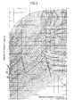
- Fig. 3 illustrates a plotting of the result of Table 1 on an h-s diagram for steam.
- electric power could be generated with thermal energy possessed by the coolant effectively by adopting a three-stage system comprised of the high-pressure turbine 30, the medium-pressure turbine 40, and the low-pressure turbine 50.
- a two-stage system comprised of the high-pressure turbine and the low-pressure turbine may be adopted or a system with four or more stages may be adopted.
- Table 2 shows a result of the simulation about power generation efficiency on the system shown in Fig. 2 .
- the DME reactor 10A was cooled in calorific value of 98.0 ⁇ 10 6 kcal/h
- the gasoline reactor 10B was cooled in calorific value of 122.4 ⁇ 10 6 kcal/h. Under such conditions, the DME reactor 10A can obtain water vapor of 30 ata and 233°C, and the gasoline reactor 10B can obtain water vapor of 100 ata and 310°C.
- saturated water vapor of 188.4 ton/h for power generation was supplied from the DME reactor 10A, and saturated water vapor of 100 ton/h for power generation was supplied from the gasoline reactor 10B.
- the saturated water vapor for superheating was supplied from the gasoline reactor 10B by 133.8 ton/h, while 42.2 ton/h (13.8 x 10 6 kcal/h as converted to calorific value) was supplied to the superheater 34 and 91.6 ton/h (29.9 x 10 6 kcal/h as converted to calorific value) was supplied to the superheater 44.
- Air discharged from the low-pressure turbine 50 was set to 0.05 ata.
- Calorific value in the heat exchanger 66 was set to 17.6 x 10 6 kcal/h.
- Table 2 Enthalpy of steam (kcal/kg) Power generation water vapor line 22A 668 Power generation water vapor line 22B, Superheating water vapor line 24 660 Power generation water vapor line 32 (before superheating) 630 Power generation water vapor line 32 (after superheating) 703 Power generation water vapor line 42 (before superheating) 605 Power generation water vapor line 42 (after superheating) 710 Water vapor collection line 52 (before condensation) 585 Water vapor collection line 52 (after condensation) 30 Superheating water vapor line 24A (after superheating) 334 Superheating water vapor line 24B (after superheating) 334 Superheating water vapor lien 24 (after heat exchange) 60.9 Coolant collection line 62 (before heat exchange) 40.9 Coolant collection line 62 (after heat exchange) 136.5
Landscapes
- Chemical & Material Sciences (AREA)
- Oil, Petroleum & Natural Gas (AREA)
- Engineering & Computer Science (AREA)
- Organic Chemistry (AREA)
- Chemical Kinetics & Catalysis (AREA)
- General Chemical & Material Sciences (AREA)
- Crystallography & Structural Chemistry (AREA)
- Combustion & Propulsion (AREA)
- Mechanical Engineering (AREA)
- General Engineering & Computer Science (AREA)
- Production Of Liquid Hydrocarbon Mixture For Refining Petroleum (AREA)
- Engine Equipment That Uses Special Cycles (AREA)
Abstract
Description
- This Application claims priority from Japanese Patent Application No.
2011-156647 filed on July 15, 2011 - The present invention relates to a method for generating electric power and for producing gasoline from methanol, and to a system therefor.
- A catalyst for converting methanol to dimethyl ether (DME) or for converting methanol to gasoline through DME was already known (e.g., Japanese Patent Application Publication No.
50-076027 51-057688 - In addition, Japanese Patent Application Publication No.
10-506668 - However, the method described in Japanese Patent Application Publication No.
10-506668 - Accordingly, in view of the above-described problems, an object of the present invention is to provide a method for producing gasoline from methanol with generation of electric power, in which, by cooling heat generated due to gasoline synthesis reaction of methanol, electric power is generated, thereby reducing total cost, and a system for the method.
- To achieve the above-described object, according to an embodiment of the present invention, there is provided a method for generating electric power and for producing gasoline from methanol, the method including the steps of: synthesizing gasoline by reacting methanol under a catalyst; recovering heat generated from the gasoline synthetic reaction of methanol by cooling the reaction with coolant to vaporize the coolant; and generating electric power by using the coolant vapor produced in the heat recovery.
- The coolant may include water. The coolant vapor may include saturated water vapor. The power generation step may include generating electric power with at least one steam turbine using the saturated water vapor. Furthermore, the power generation step may include generating electric power with a plurality of steam turbines in series, further comprising: generating electric power with a first steam turbine of the plural steam turbines using a part of the saturated water vapor; superheating exhaust steam from the first steam turbine by another part of the saturated water vapor; and generating electric power with a second steam turbine of the plural steam turbines using the superheated exhaust steam.
- According to another aspect of the present invention, there is provided a system for generating electric power and for producing gasoline from methanol, the system including: a gasoline production apparatus containing a catalyst for synthesizing gasoline from methanol, heat generated by the synthesis increasing a temperature of the gasoline production apparatus; a cooling apparatus for cooling the gasoline production apparatus with coolant to vaporize the coolant; and a power generation apparatus for generating electric power using the coolant vapor produced by the cooling apparatus.
- The coolant may include water. The vapor may include saturated water vapor. The power generation apparatus may include at least one steam turbine. Furthermore, the power generation apparatus may include a plurality of steam turbines, the system further including: a line for supplying a part of the saturated water vapor to a first steam turbine of the plurality of steam turbines; a line for supplying exhaust steam from the first steam turbine to a second steam turbine of the plurality of steam turbines; and a superheater for superheating the exhaust steam of the second steam turbine using another part of the saturated water vapor.
- According to the present invention, because heat generated by gasoline synthetic reaction of methanol is cooled with coolant and this reaction occurs at about 400°C, when the coolant is water, it is possible to obtain water vapor of about 100 kg/cm2G (saturated at 310°C). Such vapor enables power generation to be achieved sufficiently and consequently, apparatus cost and operating cost required for the cooling can be transformed to power generation cost. Thus, the system and method which can be expected to ensure a sufficient profit in terms of the total cost for gasoline production and power generation can be provided.
-
-
Fig. 1 is a schematic view showing an embodiment of a system for generating electric power and for producing gasoline according to the present invention; -
Fig. 2 is a schematic view showing another embodiment of a system for generating electric power and for producing gasoline according to the present invention; and -
Fig. 3 is an h-s diagram for steam showing changes in enthalpy and entropy of steam in the system according to the present invention. - Hereinafter, an embodiment of the present invention will be described with reference to the accompanying drawings. As shown in
Fig. 1 , a gasoline productionpower generation system 1 of the present embodiment includes mainly areactor 10 for synthesizing gasoline from methanol, and a series of turbines for generating electric power with water vapor used for cooling the reactor, namely, a high-pressure turbine 30, a medium-pressure turbine 40, and a low-pressure turbine 50. - The
reactor 10 synthesizes gasoline from methanol which is a raw material, through reactions shown in the following formulas.
2CH3OH → CH3OCH3 + H2O (formula 1)
1/2nCH3OCH3 → (CH2)n + 1/2nH2O (formula 2)
- In this way, methanol is converted to gasoline through a dimethyl ether (DME) synthetic reaction shown in
formula 1 and a gasoline synthetic reaction shown in formula 2. In thereactor 10, two kinds of the catalysts, i.e., DME synthetic catalyst and gasoline synthetic catalyst are provided on two stages, so that the two reactions can be progressed in stages. Thereactor 10 includes a catalyst layer (not shown) which is filled with these catalysts, and methanol or DME passes through this catalyst layer. As the DME synthetic catalyst, it is permissible to use known catalysts, for example, aluminosilicate type zeolite base catalyst. As the gasoline synthetic catalyst, the known catalysts such as the aluminosilicate type zeolite base catalyst may also be used. These catalysts have been disclosed in detail in Japanese Patent Application Publication No.50-076027 51-057688 - The synthetic reaction from methanol to DME is an exothermic reaction and a reaction heat thereof is 185 kcal per methanol of 1 kg. The gasoline synthetic reaction is also an exothermic reaction and a reaction heat thereof is 231 kcal per methanol of 1 kg. Thus, when synthesizing gasoline from methanol, a reaction heat thereof is 416 kcal per methanol of 1 kg. Electric power is generated using this reaction heat. As the condition for DME synthetic reaction, a pressure in a range of 35 to 45 kg/cm2 is preferred and a temperature in a range of 250 to 300°C is preferred. As the condition for gasoline synthetic reaction, a pressure in a range of 3 to 8 kg/cm2 is preferred and a temperature in a range of 380 to 450° is preferred.
- The
reactor 10 includes amethanol supply line 12 for supplying methanol to the reactor and agasoline discharge line 14 for discharging gasoline synthesized by the reactor. Thereactor 10 is cooled by coolant to control the temperature of the reactor within the above-described range. Thereactor 10 is provided with a flow path (not shown) in which coolant flows along an outer periphery of the catalyst layer (not shown). Although the coolant is not restricted to any particular type as long as it is capable of cooling thereactor 10 within the above-mentioned temperature range, water is preferred. Thus, thissystem 1 includes acoolant discharge line 16 for discharging water vapor used for cooling the reactor from the reactor, a steam-water separator 20 for separating water vapor used for cooling, and acoolant circulation line 26 for supplying water separated by the steam-water separator to the reactor again. - This
system 1 includes a power generationwater vapor line 22 for supplying saturated water vapor separated by the steam-water separator 10 in order to generate electric power with water vapor used for cooling the reactor, a power generationwater vapor line 32 for supplying water vapor used for power generation in the high-pressure turbine 30 to the medium-pressure turbine 40, and a power generationwater vapor line 42 for supplying water vapor used for power generation in the medium-pressure turbine 40, to the low-pressure turbine 50. Superheaters 34, 44 for superheating water vapor whose pressure has been lowered due to the power generation in the turbines are arranged in the power generationwater vapor line 32 and the power generationwater vapor line 42, which are located between the turbines. Thesuperheaters water vapor lines water separator 20. - This
system 1 is provided with a watervapor collection line 52 for collecting water vapor from the low-pressure turbine in order to use the water vapor used for power generation in the low-pressure turbine 50 as coolant again. Thisvapor collection line 52 includes acondenser 54 for condensing water vapor. Further, thissystem 1 includes acondenser 60 for condensing and collecting the water vapor, which has undergone heat exchange by thesuperheaters system 1 includes acoolant collection line 62 for carrying the coolant condensed by thecondenser 54 and the coolant existing within thecondenser 60, to the steam-water separator 20. In the meantime, thevapor collection line 52 and thecoolant collection line 62 havepumps - In this
system 1 having the above configuration, first, methanol, which is a raw material, is supplied to thereactor 10 through amethanol supply line 12. Thereactor 10 induces DME synthetic reaction and gasoline synthetic reaction under a predetermined temperature and pressure to synthesize gasoline through the DME. Gasoline is discharged through thegasoline discharge line 14 and carried to a storage facility (not shown). Because both the DME synthetic reaction and the gasoline synthetic reaction are exothermic reactions, thereactor 10 is cooled with water as coolant in order to keep the reactor at a predetermined temperature. Consequently, the coolant turns to supersaturated water vapor, which is carried to the steam-water separator 20 through thecoolant discharge line 16. - The steam-
water separator 20 separates the supersaturated steam to saturated water vapor and water, and the water is carried to thereactor 10 through thecoolant circulation line 26 to be used as coolant again. On the other hand, part of the saturated water vapor is carried to the high-pressure turbine 30 through the power generationwater vapor line 22 and other part of the saturated water vapor is carried to thewater vapor superheaters - By inflating the saturated water vapor in the high-
pressure turbine 30, the turbine is driven with its kinetic energy to generate electric power. Because the water vapor used in power generation by the high-pressure turbine 30 is in a supersaturated condition with a reduced pressure, the water vapor is superheated with thesuperheater 34 through the power generationwater vapor line 32 to turn into a saturated or lower state and then is supplied to the medium-pressure turbine 40. - By inflating the saturated water vapor in the medium-
pressure turbine 40 also, the turbine is driven with its kinetic energy to generate electric power. The supersaturated water vapor used in power generation in the medium-pressure turbine 40 is superheated by thesuperheater 44 through the power generationwater vapor line 42 to turn into a saturated or lower state, and supplied to the low-pressure turbine 50. Generation of electric power is carried out in the medium-pressure turbine 50 also. - The water vapor used in power generation by the low-
pressure turbine 50 is collected by the watervapor collection line 52 and condensed by thecondenser 54. The condensed coolant is carried to thecondenser 60 by apump 56. The superheating water vapor, which has undergone heat exchange with the power generation water vapor in thesuperheaters condenser 60 through the superheatingwater vapor lines condenser 60 is returned to the steam-water separator 20 through thecoolant collection line 62 and apump 64, and used for cooling of thereactor 10 again. - The embodiment shown in
Fig. 1 indicates a case of providing thereactor 10, which synthesizes gasoline from methanol by executing the two reactions based onformulas 1 and 2. However, as shown inFig. 2 , together with agasoline reactor 10B for synthesizing gasoline, it is permissible to provide a dimethyl ether (DME)reactor 10A for obtaining dimethyl ether through only the reaction offormula 1. Consequently, the DME can be produced as well as gasoline. The DME is available as a fuel alternate to liquid petroleum gas (LPG). - In this case, as shown in
Fig. 2 , theDME reactor 10A and thegasoline reactor 10B are provided with steam-water separators coolant circulation lines water vapor line 22B from thegasoline reactor 10B is extended up to the high-pressure turbine 30, and a power generationwater vapor line 22A from theDME reactor 10A is extended up to a power generation water vapor line located between the high-pressure turbine 30 and the medium-pressure turbine 40. Because, as described above, the reaction temperature and the reaction heat are lower in the DME synthetic reaction than in the gasoline synthetic reaction, supplying the water vapor used for cooling theDME reactor 10A to the medium-pressure turbine 40 enables thermal energy to be recovered more effectively. - Further, as shown in
Fig. 2 , aheat exchanger 66 may be provided on a downstream side of thesuperheaters water vapor lines heat exchanger 66, the condensed coolant flowing through thecoolant collection line 62 is heated by the superheating water vapor superheated by the superheaters. Consequently, the entire thermal efficiency can be increased by preheating coolants in thecoolant collection lines - Although in the embodiment shown in
Fig. 1 , the DME synthetic reaction and the gasoline synthetic reaction for producing gasoline from methanol are executed with thesingle reactor 10, these reactions may be carried out with independent reactors each. In this case, a line for supplying DME is provided between the DME reactor which carries out the DME synthetic reaction shown informula 1 mentioned above and the gasoline reactor which carries out the gasoline synthetic reaction shown in formula 2 mentioned above. - Although the gasoline production power generation system of the present invention may be built at a place of production of methanol, which is a raw material, or a place of production of natural gas, which is a raw material for methanol, it is preferred to be built at a consumption place of gasoline or nearby places. Because methanol remains in a liquid state at a normal temperature and normal pressure, and is easy to handle, transportation of the methanol to a consumption area of gasoline or nearby areas, for example, metropolitan area after the methanol is produced at a production place of natural gas such as Middle Eastern area enables transportation cost to be reduced largely compared to transportation of natural gas in a liquefied state. Further, because the consumption place of gasoline usually has a high demand for electric power, electric power can be supplied effectively to users by generating the electric power at the consumption place of gasoline or nearby areas. Example
- A simulation about power generation efficiency was carried out on a system shown in
Fig. 1 . Table 1 andFig. 3 show a result thereof. In the meantime, thereactor 10 was cooled under a condition of using water as coolant and cooling in calorific value of 80.9 × 10⁶ kcal/h and another condition that an obtained water vapor was at 100 ata and 310°C. Further, as a predetermined condition, this saturated water vapor was supplied to the high-pressure turbine 30 by 100 ton/h for the purpose of power generation and by 54.6 ton/h for the purpose of superheating. Of this amount of the water vapor, 22.4 ton/h (7.3 x 10⁶ kcal/h as converted to calorific value) was supplied to thesuperheater 34 and 32.2 ton/h was supplied to thesuperheater 44. Air discharged from the low-pressure turbine 50 was set to 0.05 ata. -
Table 1 Enthalpy of steam (kcal/kg) Power generation water vapor line 22, Superheatingwater vapor line 24660 Power generation water vapor line 32 (before superheating) 630 Power generation water vapor line 32 (after superheating) 730 Power generation water vapor line 42 (before superheating) 605 Power generation water vapor line 42 (after superheating) 710 Water vapor collection line 52 (before condensation) 585 Water vapor collection line 52 (after condensation) 30 Superheating water vapor line 24A (after superheating)334 Superheating water vapor line 24B (after superheating)334 -
Fig. 3 illustrates a plotting of the result of Table 1 on an h-s diagram for steam. As shown inFig. 3 , electric power could be generated with thermal energy possessed by the coolant effectively by adopting a three-stage system comprised of the high-pressure turbine 30, the medium-pressure turbine 40, and the low-pressure turbine 50. Of course, a two-stage system comprised of the high-pressure turbine and the low-pressure turbine may be adopted or a system with four or more stages may be adopted. - As a result, electric power generated by the high-
pressure turbine 30 was 3,488 kw, electric power generated by the medium-pressure turbine 40 was 11,395 kw, and electric power generated by the low-pressure turbine 50 was 14,535 kw. The total output was 29,418 kw. Because input heat was 80.9 x 10⁶ kcal/h, a steam efficiency of 31.3% could be attained. - Table 2 shows a result of the simulation about power generation efficiency on the system shown in
Fig. 2 . TheDME reactor 10A was cooled in calorific value of 98.0 × 10⁶ kcal/h, and thegasoline reactor 10B was cooled in calorific value of 122.4 × 10⁶ kcal/h. Under such conditions, theDME reactor 10A can obtain water vapor of 30 ata and 233°C, and thegasoline reactor 10B can obtain water vapor of 100 ata and 310°C. As another predetermined condition, saturated water vapor of 188.4 ton/h for power generation was supplied from theDME reactor 10A, and saturated water vapor of 100 ton/h for power generation was supplied from thegasoline reactor 10B. Further, the saturated water vapor for superheating was supplied from thegasoline reactor 10B by 133.8 ton/h, while 42.2 ton/h (13.8 x 10⁶ kcal/h as converted to calorific value) was supplied to thesuperheater 34 and 91.6 ton/h (29.9 x 10⁶ kcal/h as converted to calorific value) was supplied to thesuperheater 44.
Air discharged from the low-pressure turbine 50 was set to 0.05 ata. Calorific value in theheat exchanger 66 was set to 17.6 x 10⁶ kcal/h. -
Table 2 Enthalpy of steam (kcal/kg) Power generation water vapor line 22A668 Power generation water vapor line 22B, Superheatingwater vapor line 24660 Power generation water vapor line 32 (before superheating) 630 Power generation water vapor line 32 (after superheating) 703 Power generation water vapor line 42 (before superheating) 605 Power generation water vapor line 42 (after superheating) 710 Water vapor collection line 52 (before condensation) 585 Water vapor collection line 52 (after condensation) 30 Superheating water vapor line 24A (after superheating)334 Superheating water vapor line 24B (after superheating)334 Superheating water vapor lien 24 (after heat exchange) 60.9 Coolant collection line 62 (before heat exchange) 40.9 Coolant collection line 62 (after heat exchange) 136.5 - In the system shown in
Fig. 2 , electric power generated by the high-pressure turbine 30 was 3,488 kw, electric power generated by the medium-pressure turbine 40 was 32,400 kw, electric power generated by the low-pressure turbine 50 was 41,340 kw, and a total output was 77,228 kw. Because total input heat was 220.4 x 10⁶ kcal/h, steam efficiency of 30.1 % could be attained.
Claims (6)
- A method for generating electric power and for producing gasoline from methanol, the method comprising the steps of:synthesizing gasoline by reacting methanol under a catalyst;recovering heat generated from the gasoline synthetic reaction of methanol by cooling the reaction with coolant to vaporize the coolant; andgenerating electric power by using the coolant vapor produced in the heat recovery.
- The method according to claim 1, wherein the coolant comprises water, the coolant vapor comprises saturated water vapor, and the power generation step comprises generating electric power with at least one steam turbine using the saturated water vapor.
- The method according to claim 2, wherein the power generation step comprises generating electric power with a plurality of steam turbines in series, further comprising:generating electric power with a first steam turbine of the plural steam turbines using a part of the saturated water vapor;superheating exhaust steam from the first steam turbine by another part of the saturated water vapor; andgenerating electric power with a second steam turbine of the plural steam turbines using the superheated exhaust steam.
- A system for generating electric power and for producing gasoline from methanol, the system comprising:a gasoline production apparatus containing a catalyst for synthesizing gasoline from methanol, heat generated by the synthesis increasing a temperature of the gasoline production apparatus;a cooling apparatus for cooling the gasoline production apparatus with coolant to vaporize the coolant; anda power generation apparatus for generating electric power using the coolant vapor produced by the cooling apparatus.
- The system according to claim 4, wherein the coolant comprises water, the vapor comprises saturated water vapor, and the power generation apparatus comprises at least one steam turbine.
- The system according to claim 5, wherein the power generation apparatus comprises a plurality of steam turbines, and wherein the system further comprises:a line for supplying a part of the saturated water vapor to a first steam turbine of the plurality of steam turbines;a line for supplying exhaust steam from the first steam turbine to a second steam turbine of the plurality of steam turbines; anda superheater for superheating the exhaust steam of the second steam turbine using another part of the saturated water vapor.
Applications Claiming Priority (1)
| Application Number | Priority Date | Filing Date | Title |
|---|---|---|---|
| JP2011156647A JP5798821B2 (en) | 2011-07-15 | 2011-07-15 | Method and system for producing gasoline from methanol and generating electricity |
Publications (1)
| Publication Number | Publication Date |
|---|---|
| EP2546322A1 true EP2546322A1 (en) | 2013-01-16 |
Family
ID=46640549
Family Applications (1)
| Application Number | Title | Priority Date | Filing Date |
|---|---|---|---|
| EP12175081A Withdrawn EP2546322A1 (en) | 2011-07-15 | 2012-07-05 | Method for generating electricity and for producing gasoline from methanol and system therefor |
Country Status (3)
| Country | Link |
|---|---|
| US (2) | US9193918B2 (en) |
| EP (1) | EP2546322A1 (en) |
| JP (1) | JP5798821B2 (en) |
Families Citing this family (2)
| Publication number | Priority date | Publication date | Assignee | Title |
|---|---|---|---|---|
| CN105399592B (en) * | 2015-11-04 | 2017-05-10 | 鹤壁宝发能源科技股份有限公司 | System and technology for co-producing mixed olefin, arene and liquefied gas from crude dimethyl ether |
| CN107023339B (en) * | 2017-05-26 | 2018-04-03 | 四川开山新玛能源科技有限公司 | A kind of classification series connection method for controlling cooling system of low temperature hot fluid |
Citations (10)
| Publication number | Priority date | Publication date | Assignee | Title |
|---|---|---|---|---|
| JPS5076027A (en) | 1973-08-09 | 1975-06-21 | ||
| JPS5157688A (en) | 1974-09-23 | 1976-05-20 | Mobil Oil | Ringanjushokubai oyobi sonoseizoho |
| US4263141A (en) * | 1978-10-26 | 1981-04-21 | Metallgesellschaft Aktiengesellschaft | Process of producing gasoline from synthesis gas |
| JPS5714685A (en) * | 1980-06-30 | 1982-01-25 | Mitsubishi Heavy Ind Ltd | Recovering method for heat of reaction |
| US4338475A (en) * | 1979-10-30 | 1982-07-06 | Mobil Oil Corporation | Converting alcohols to hydrocarbons |
| EP0103914A2 (en) * | 1982-08-26 | 1984-03-28 | Shell Internationale Researchmaatschappij B.V. | Process for the generation of power and the preparation of liquid hydrocarbons |
| EP0108482A1 (en) * | 1982-10-01 | 1984-05-16 | Mobil Oil Corporation | Heat transfer circuit for generation of steam in conversion of methanol to gasoline |
| JPH10506668A (en) | 1994-11-09 | 1998-06-30 | スターケム テクノロジーズ インコーポレイテッド | How to convert methanol to gasoline |
| WO2008073186A2 (en) * | 2006-10-26 | 2008-06-19 | Marshall Medoff | Processing biomass |
| CN101712884A (en) * | 2009-09-14 | 2010-05-26 | 国科瑞德(北京)能源科技发展有限公司 | Co-production device for producing hydrocarbon through methanol dehydration as well as cold, heat and power |
Family Cites Families (7)
| Publication number | Priority date | Publication date | Assignee | Title |
|---|---|---|---|---|
| US3894103A (en) | 1973-08-09 | 1975-07-08 | Mobil Oil Corp | Aromatization reactions |
| US3906054A (en) | 1974-09-23 | 1975-09-16 | Mobil Oil Corp | Alkylation of olefins |
| JP2006138288A (en) * | 2004-11-15 | 2006-06-01 | Sanden Corp | Heat engine |
| RU2008140161A (en) * | 2006-03-30 | 2010-05-10 | Ниппон Стил Инджиниринг Ко., Лтд. (Jp) | LIQUID FUEL SYNTHESIS SYSTEM |
| RU2448147C2 (en) * | 2006-12-13 | 2012-04-20 | Хальдор Топсеэ А/С | Method for synthesis of hydrocarbon components of gasoline |
| JP5103282B2 (en) * | 2008-05-30 | 2012-12-19 | 旭化成ケミカルズ株式会社 | Fluidized bed reactor and gas phase exothermic reaction method using the same |
| JP5331890B2 (en) * | 2009-09-16 | 2013-10-30 | 株式会社日立製作所 | Cogeneration plant and biomass reforming combined power plant |
-
2011
- 2011-07-15 JP JP2011156647A patent/JP5798821B2/en not_active Expired - Fee Related
-
2012
- 2012-07-05 EP EP12175081A patent/EP2546322A1/en not_active Withdrawn
- 2012-07-12 US US13/547,272 patent/US9193918B2/en not_active Expired - Fee Related
-
2015
- 2015-10-19 US US14/886,880 patent/US20160040076A1/en not_active Abandoned
Patent Citations (10)
| Publication number | Priority date | Publication date | Assignee | Title |
|---|---|---|---|---|
| JPS5076027A (en) | 1973-08-09 | 1975-06-21 | ||
| JPS5157688A (en) | 1974-09-23 | 1976-05-20 | Mobil Oil | Ringanjushokubai oyobi sonoseizoho |
| US4263141A (en) * | 1978-10-26 | 1981-04-21 | Metallgesellschaft Aktiengesellschaft | Process of producing gasoline from synthesis gas |
| US4338475A (en) * | 1979-10-30 | 1982-07-06 | Mobil Oil Corporation | Converting alcohols to hydrocarbons |
| JPS5714685A (en) * | 1980-06-30 | 1982-01-25 | Mitsubishi Heavy Ind Ltd | Recovering method for heat of reaction |
| EP0103914A2 (en) * | 1982-08-26 | 1984-03-28 | Shell Internationale Researchmaatschappij B.V. | Process for the generation of power and the preparation of liquid hydrocarbons |
| EP0108482A1 (en) * | 1982-10-01 | 1984-05-16 | Mobil Oil Corporation | Heat transfer circuit for generation of steam in conversion of methanol to gasoline |
| JPH10506668A (en) | 1994-11-09 | 1998-06-30 | スターケム テクノロジーズ インコーポレイテッド | How to convert methanol to gasoline |
| WO2008073186A2 (en) * | 2006-10-26 | 2008-06-19 | Marshall Medoff | Processing biomass |
| CN101712884A (en) * | 2009-09-14 | 2010-05-26 | 国科瑞德(北京)能源科技发展有限公司 | Co-production device for producing hydrocarbon through methanol dehydration as well as cold, heat and power |
Also Published As
| Publication number | Publication date |
|---|---|
| US20130014430A1 (en) | 2013-01-17 |
| JP5798821B2 (en) | 2015-10-21 |
| US20160040076A1 (en) | 2016-02-11 |
| JP2013024046A (en) | 2013-02-04 |
| US9193918B2 (en) | 2015-11-24 |
Similar Documents
| Publication | Publication Date | Title |
|---|---|---|
| US6265453B1 (en) | Hydrocarbon conversion system with enhanced combustor and method | |
| CN102530865B (en) | Be there is the method for being produced hydrogen by steam reformation petroleum fractions of the production of steam of optimization | |
| EP3849939B1 (en) | Process for the synthesis of ammonia | |
| AU2012283712B2 (en) | Advanced combined cycle systems and methods based on methanol indirect combustion | |
| CN104134478B (en) | A kind of nuclear energy and biomass energy association system and method | |
| CN203096014U (en) | Device for producing natural gas from factory waste gas | |
| AU2013319303B2 (en) | Method and system for producing liquid fuel and generating electric power | |
| US9193918B2 (en) | Method for generating electricity and for producing gasoline from methanol and system therefor | |
| CN101659879B (en) | Chemical-electric poly-generation method and equipment | |
| Li et al. | Performance comparison of two low-CO2 emission solar/methanol hybrid combined cycle power systems | |
| CN103557597B (en) | A kind of MTP reaction mixture gas heat recovery method | |
| CN100584924C (en) | A method for co-producing oil products, methanol and electric energy with combustible carbon-containing solids as raw materials | |
| US20110131992A1 (en) | Co-production of synthesis gas and power | |
| KR101241527B1 (en) | Annular methanation reactor, and apparatus for producing synthetic natural gas using the same | |
| JP6116801B2 (en) | System or method for producing gasoline | |
| CN103911196A (en) | Method and apparatus for utilizing plant waste gas to prepare natural gas | |
| CN117427569A (en) | A system and method for producing methanol by hydrogenating carbon dioxide | |
| CN109761748A (en) | A kind of separation method and device of synthesis gas to methanol product based on thermal high fraction process | |
| CN107974319B (en) | Sulfur-tolerant methanation process for preparing substitute natural gas from coal | |
| Kansha et al. | Simulated application of self-heat recuperation and pressure swing system to industrial methanol synthesis process | |
| CN108219879A (en) | Coal system substitute natural gas without cycle methanation in presence of sulfur technique | |
| EP4713419A1 (en) | Nuclear heat integration with steam cracking process | |
| Sharapov et al. | Increasing the Energy Efficiency of Biodiesel Production Plants Using a Liquid-Vapor Jet Apparatus | |
| GB2082574A (en) | Methanol synthesis | |
| Doty et al. | Windfuels–Competitive Transportation Fuels from Wind Energy and Waste CO2 |
Legal Events
| Date | Code | Title | Description |
|---|---|---|---|
| PUAI | Public reference made under article 153(3) epc to a published international application that has entered the european phase |
Free format text: ORIGINAL CODE: 0009012 |
|
| AK | Designated contracting states |
Kind code of ref document: A1 Designated state(s): AL AT BE BG CH CY CZ DE DK EE ES FI FR GB GR HR HU IE IS IT LI LT LU LV MC MK MT NL NO PL PT RO RS SE SI SK SM TR |
|
| AX | Request for extension of the european patent |
Extension state: BA ME |
|
| 17P | Request for examination filed |
Effective date: 20130716 |
|
| RBV | Designated contracting states (corrected) |
Designated state(s): AL AT BE BG CH CY CZ DE DK EE ES FI FR GB GR HR HU IE IS IT LI LT LU LV MC MK MT NL NO PL PT RO RS SE SI SK SM TR |
|
| 17Q | First examination report despatched |
Effective date: 20151120 |
|
| STAA | Information on the status of an ep patent application or granted ep patent |
Free format text: STATUS: THE APPLICATION IS DEEMED TO BE WITHDRAWN |
|
| 18D | Application deemed to be withdrawn |
Effective date: 20180320 |