EP2545880A1 - Implant extraction method and trephine drill for facilitating the extraction - Google Patents
Implant extraction method and trephine drill for facilitating the extraction Download PDFInfo
- Publication number
- EP2545880A1 EP2545880A1 EP11718760A EP11718760A EP2545880A1 EP 2545880 A1 EP2545880 A1 EP 2545880A1 EP 11718760 A EP11718760 A EP 11718760A EP 11718760 A EP11718760 A EP 11718760A EP 2545880 A1 EP2545880 A1 EP 2545880A1
- Authority
- EP
- European Patent Office
- Prior art keywords
- implant
- torque
- drill bit
- bone
- trephine drill
- Prior art date
- Legal status (The legal status is an assumption and is not a legal conclusion. Google has not performed a legal analysis and makes no representation as to the accuracy of the status listed.)
- Granted
Links
Images


Classifications
-
- A—HUMAN NECESSITIES
- A61—MEDICAL OR VETERINARY SCIENCE; HYGIENE
- A61B—DIAGNOSIS; SURGERY; IDENTIFICATION
- A61B17/00—Surgical instruments, devices or methods
- A61B17/16—Instruments for performing osteoclasis; Drills or chisels for bones; Trepans
-
- A—HUMAN NECESSITIES
- A61—MEDICAL OR VETERINARY SCIENCE; HYGIENE
- A61B—DIAGNOSIS; SURGERY; IDENTIFICATION
- A61B17/00—Surgical instruments, devices or methods
- A61B17/16—Instruments for performing osteoclasis; Drills or chisels for bones; Trepans
- A61B17/1695—Trepans or craniotomes, i.e. specially adapted for drilling thin bones such as the skull
-
- A—HUMAN NECESSITIES
- A61—MEDICAL OR VETERINARY SCIENCE; HYGIENE
- A61C—DENTISTRY; APPARATUS OR METHODS FOR ORAL OR DENTAL HYGIENE
- A61C8/00—Means to be fixed to the jaw-bone for consolidating natural teeth or for fixing dental prostheses thereon; Dental implants; Implanting tools
- A61C8/0089—Implanting tools or instruments
-
- A—HUMAN NECESSITIES
- A61—MEDICAL OR VETERINARY SCIENCE; HYGIENE
- A61B—DIAGNOSIS; SURGERY; IDENTIFICATION
- A61B17/00—Surgical instruments, devices or methods
- A61B17/16—Instruments for performing osteoclasis; Drills or chisels for bones; Trepans
- A61B17/1637—Hollow drills or saws producing a curved cut, e.g. cylindrical
-
- A—HUMAN NECESSITIES
- A61—MEDICAL OR VETERINARY SCIENCE; HYGIENE
- A61C—DENTISTRY; APPARATUS OR METHODS FOR ORAL OR DENTAL HYGIENE
- A61C1/00—Dental machines for boring or cutting ; General features of dental machines or apparatus, e.g. hand-piece design
- A61C1/08—Machine parts specially adapted for dentistry
- A61C1/082—Positioning or guiding, e.g. of drills
- A61C1/084—Positioning or guiding, e.g. of drills of implanting tools
-
- A—HUMAN NECESSITIES
- A61—MEDICAL OR VETERINARY SCIENCE; HYGIENE
- A61C—DENTISTRY; APPARATUS OR METHODS FOR ORAL OR DENTAL HYGIENE
- A61C3/00—Dental tools or instruments
- A61C3/02—Tooth drilling or cutting instruments; Instruments acting like a sandblast machine
Definitions
- the invention relates to a method for extracting osseointegrated implants, and a design for a trephine drill bit that is especially suitable for executing said method.
- Bone implants in general and dental implants in particular are biologically and mechanically designed to osseointegrate, in other words to join and fix themselves to the bone in a manner sufficiently strong for them to be able to withstand the high mechanical stresses the bone in which they are installed has to withstand. Because of this, the bone-implant connection in practice is very strong and is designed not to break easily.
- implants sometimes have to be removed from the bone in which they are osseointegrated (in the event of their incorrect installation or a change in the medical treatment of the area, etc).
- removal of an implant is a complex task due to the nature of the connection between the implant and the bone, which, as mentioned above, must be strong.
- the removal of an osseointegrated implant is a process that can be somewhat traumatic for the bone and therefore for the patient.
- the traditional extraction procedure involves drilling with a hollow drill bit known as a 'trephine drill bit' around the implant. An area including the implant itself and a section of the surrounding bone is drilled. Once drilling is finished, the implant and said section of surrounding bone are removed. Unfortunately, this procedure leaves a cavity in the patient's bone that is larger than the cavity originally occupied by the implant, which is a negative factor as said cavity is usually too large for fitting another implant; because of this, a bone regeneration process is usually necessary in order to fill the cavity prior to continuing with the implant treatment.
- Said extraction tool comprises an external thread capable of being threaded into the blind hole of the implant, in an opposite direction to the external thread between the implant and the bone.
- the extraction procedure is based on threading the extraction tool inside the implant, by means of an additional torque application tool (e.g. the tool described in US patent application 12/619079 ), slightly deforming the head of the implant.
- the extraction tool is threaded until the rotation torque is so high that the fastening between the extraction tool and the implant reaches its maximum point and said rotation torque is transferred to the implant-bone connection, eventually causing the breakage of the connection and the unthreading of the implant (or the simple breakage, in the event that the implant is not threaded to the bone).
- the extraction tool In order for this procedure to be executed, therefore, the extraction tool must be able to withstand high torques and to transfer said torques to the implant. Then, by means of the aforementioned extraction tool, the implant is removed cleanly, leaving behind it only the bone cavity occupied by the implant. As a result, there is no need to perform a subsequent bone regeneration phase, in addition to the fact that the process of extracting the implant is evidently made less traumatic for the patient.
- the method should make maximum use of the torque applied, with the result that it is not necessary to apply excessively high torques to bring about the breakage of said connection.
- the objective is that the surgeon should not have to exert a large amount of effort to break the implant-bone connection (as there is a risk of the extraction tool breaking under very high torques), and that, with the application of a specific maximum torque, stronger bone-implant connections may be broken than with the aforementioned method.
- an extraction torque is applied on the extraction tool until a specific maximum torque value is reached; the application of said torque is then eased.
- the specific maximum torque value increases in each successive phase.
- an increasing extraction torque is applied on the extraction tool until a specific maximum torque value is reached; the application of torque is then eased or stopped; an increasing extraction torque is applied once more up to a specific maximum torque value greater than the previous one; the application is eased once more, and so on until the connection between the implant and the bone is broken.
- the method according to the invention based on the gradual application of increasing torques in phases and with pauses, provides better results than the basic method described in WO2009153372 , based on the application of an increasing extraction torque on the implant until, directly and without any pauses, the connection between the implant-bone is broken. It has been shown in testing that this method brings about a gradual and controlled deformation of the head of the implant, with the result that the extraction tool becomes more deeply inserted into the implant. The new effect is very important (in view of the fact that the extraction tool usually has a top part that increases in diameter) because the area of the extraction tool that withstands the stresses has a larger diameter and is therefore stronger, thereby enabling the application of higher breakage torques without damage being caused to the extraction tool.
- the invention relates to a method for extracting an implant installed in a bone, the method comprising the application of a torque on an extraction tool in order to thread it in the interior of the implant until the implant-bone connection breaks, with the specific feature that in said method the extraction torque is applied in successive phases. In each phase, an extraction torque is applied on the extraction tool until a specific maximum torque value is reached, and the application of said torque is then eased, said specific maximum torque value increasing in each successive phase.
- the extraction tool is placed inside the head of the implant and, by means of a torque-application tool, an increasing and gradual extraction torque is applied in the fastening direction of the extraction tool (generally in an anti-clockwise direction) until a first maximum torque value is reached.
- Said torque application tool is preferably an adjustable maximum torque wrench, such as the one described in US patent application 12/619079 .
- the extraction tool is unthreaded, without it having to be removed completely.
- a torque is applied once more on the extraction tool until a second maximum torque value, greater than the previous one, is reached. This methodology is repeated, safeguarding the useful life of the extraction tool until the osseointegration between the implant and the bone is broken and the implant extracted.
- the method described herein enables the controlled deformation of the head of the implant as the extraction tool is threaded and, consequently, the deeper insertion of the extraction tool inside the implant.
- the diameter of the extraction tool increases towards its apex, the area of the tool that applies the torque on the implant and withstands the stresses has a larger diameter (and is therefore stronger).
- the extraction tool is capable of applying and withstanding higher torques. The surgeon is thus able break stronger implant-bone connections without breaking the extraction tool. In laboratory testing it has been shown that the inventive procedure allows torques up to 60% higher to be applied without the extraction tool breaking.
- the extraction method according to the invention comprises the additional step, in each phase (once the torque has been eased and before the application of a greater extraction torque in the next phase), of applying a torque in a direction opposite to the extraction direction in order to detach the extraction tool from the implant.
- This enables the extraction tool to enter further into the implant.
- the extraction tool has a diameter that decreases towards its apex (in other words, a diameter that increases towards its top area)
- the fact that it is introduced further into the implant means that the active diameter of the extraction tool is increased.
- the strength of the connection between the extraction tool and the implant is increased considerably.
- the inventive method optionally comprises the additional step of making in incision with a trephine drill bit in an external part of the implant-bone connection.
- the outermost area of the implant-bone connection is the area in which Bone-Implant Contact (BIC) is at its greatest.
- BIC Bone-Implant Contact
- Figure 1 shows a cross-sectional view of an implant (1), in this case a dental implant, installed in a bone and to which an extraction tool (2) is connected.
- the extraction tool (2) is of the type that is used to perform the method according to the invention, thus comprising a threaded body (4) that is threaded into the blind threaded hole (3) of the implant (1).
- the threaded body (4) is inserted until it is so strongly threaded that the application of even greater torques on the extraction tool (2) causes the implant-bone connection to break.
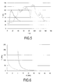
- the trephining has two main effects. Firstly, it enables the point of application of the greatest stresses on the extraction tool (2) to be transferred to the implant (1), from the original point (7), without trephining, to the current point (6), which corresponds with an area of bone that is not as strong as that of the original point (7). Secondly, the stress on the current point (6), with trephining, is considerably greater than the stress on the original point (7), without trephining. This effect may be seen in Figure 6 , which shows the stress applied on the bone in accordance with the depth of the point of application.
- Figure 2 shows an elevated view of an embodiment of the trephine drill bit (8) according to the invention, which enables the trephining described above to be carried out safely and accurately on the outermost area (5) of the implant-bone connection.
- the outermost area of the trephine drill bit (8) comprises a reduced area (9) of a smaller diameter than the rest of the body of the trephine drill bit (8). Said reduced area (9) ends in a stop (10) that guides the surgeon during trephining and tells him/her when they have to insert the trephine drill bit (8).
- the stop (10) operates in such a way that, when the stop (10) comes into contact with the bone while trephining, the stop (10) does not cut or pull the bone but merely rubs against it.
- Figure 3 shows a partial schematic cross-sectional view of a second embodiment of the trephine drill bit according to the invention.
- the trephine drill bit (8') comprises a body (11) and a tip (12), the latter being of a smaller diameter than the body (11) and being connected to it by means, for example, of a transverse fixing member (13), as shown in the figure.
- the reduced area (9) of the trephine drill bit (8') is on the tip (12) itself, while the end of the body (11) provides the stop (10).
- the advantage of this embodiment is that it allows a body (11) of one material (generally durable and not fragile) and a tip (12) of another material (generally hard) to be used.
- Figure 4 shows an enlarged view of the area of Figure 3 where the stop (10) is situated, more clearly illustrating all the aforementioned elements of the trephine drill bit (8').
- Figure 5 shows a graph of the temperature the bone acquires in accordance with the trephining time, the maximum temperature values generated using the trephine drill bit according to the invention (dashed line) and a conventional trephine drill bit (dotted line) being compared.
- the maximum temperature values acquired by the bone surrounding the trephine drill bit are lower throughout the trephining (lasting between 0 and 50 seconds in the case shown) in comparison to the maximum temperature values generated when trephining with a conventional trephine drill bit (a longer period of trephining lasting between 0 and 160 seconds).
- the use of the trephine drill bit according to the invention offers the additional advantage of preserving the quality of the bone surrounding the implant during the extraction.
Landscapes
- Health & Medical Sciences (AREA)
- Life Sciences & Earth Sciences (AREA)
- Oral & Maxillofacial Surgery (AREA)
- Dentistry (AREA)
- Animal Behavior & Ethology (AREA)
- General Health & Medical Sciences (AREA)
- Public Health (AREA)
- Veterinary Medicine (AREA)
- Surgery (AREA)
- Orthopedic Medicine & Surgery (AREA)
- Epidemiology (AREA)
- Nuclear Medicine, Radiotherapy & Molecular Imaging (AREA)
- Engineering & Computer Science (AREA)
- Biomedical Technology (AREA)
- Heart & Thoracic Surgery (AREA)
- Medical Informatics (AREA)
- Molecular Biology (AREA)
- Neurosurgery (AREA)
- Dental Prosthetics (AREA)
- Surgical Instruments (AREA)
- Prostheses (AREA)
- Materials For Medical Uses (AREA)
Abstract
Description
- The invention relates to a method for extracting osseointegrated implants, and a design for a trephine drill bit that is especially suitable for executing said method.
- Bone implants in general and dental implants in particular are biologically and mechanically designed to osseointegrate, in other words to join and fix themselves to the bone in a manner sufficiently strong for them to be able to withstand the high mechanical stresses the bone in which they are installed has to withstand. Because of this, the bone-implant connection in practice is very strong and is designed not to break easily.
- Nevertheless, implants sometimes have to be removed from the bone in which they are osseointegrated (in the event of their incorrect installation or a change in the medical treatment of the area, etc). Generally speaking, the removal of an implant is a complex task due to the nature of the connection between the implant and the bone, which, as mentioned above, must be strong.
- The removal of an osseointegrated implant is a process that can be somewhat traumatic for the bone and therefore for the patient. The traditional extraction procedure involves drilling with a hollow drill bit known as a 'trephine drill bit' around the implant. An area including the implant itself and a section of the surrounding bone is drilled. Once drilling is finished, the implant and said section of surrounding bone are removed. Unfortunately, this procedure leaves a cavity in the patient's bone that is larger than the cavity originally occupied by the implant, which is a negative factor as said cavity is usually too large for fitting another implant; because of this, a bone regeneration process is usually necessary in order to fill the cavity prior to continuing with the implant treatment.
- The applicant recently designed a new tool for extracting implants, described in patent application
WO2009153372 , which enables dental implants to be extracted without the need to drill the bone around the implant. Said extraction tool comprises an external thread capable of being threaded into the blind hole of the implant, in an opposite direction to the external thread between the implant and the bone. The extraction procedure is based on threading the extraction tool inside the implant, by means of an additional torque application tool (e.g. the tool described inUS patent application 12/619079 - It is an objective of this invention to provide an improved implant extraction method, based on the application of a high extraction torque on the implant, which is in turn transferred to the osseointegrated implant-bone connection. The method should make maximum use of the torque applied, with the result that it is not necessary to apply excessively high torques to bring about the breakage of said connection. The objective is that the surgeon should not have to exert a large amount of effort to break the implant-bone connection (as there is a risk of the extraction tool breaking under very high torques), and that, with the application of a specific maximum torque, stronger bone-implant connections may be broken than with the aforementioned method.
- It is an object of this invention to provide a method for extracting an implant installed in a bone, which comprises the application of torque on an extraction tool in order to thread it in the interior of the implant until the implant-bone connection breaks, with the specific feature that in said method the extraction torque is applied in successive phases. In each phase, an extraction torque is applied on the extraction tool until a specific maximum torque value is reached; the application of said torque is then eased. The specific maximum torque value increases in each successive phase. In other words, in the inventive method an increasing extraction torque is applied on the extraction tool until a specific maximum torque value is reached; the application of torque is then eased or stopped; an increasing extraction torque is applied once more up to a specific maximum torque value greater than the previous one; the application is eased once more, and so on until the connection between the implant and the bone is broken.
- The method according to the invention, based on the gradual application of increasing torques in phases and with pauses, provides better results than the basic method described in
WO2009153372 , based on the application of an increasing extraction torque on the implant until, directly and without any pauses, the connection between the implant-bone is broken. It has been shown in testing that this method brings about a gradual and controlled deformation of the head of the implant, with the result that the extraction tool becomes more deeply inserted into the implant. The new effect is very important (in view of the fact that the extraction tool usually has a top part that increases in diameter) because the area of the extraction tool that withstands the stresses has a larger diameter and is therefore stronger, thereby enabling the application of higher breakage torques without damage being caused to the extraction tool. - Details of the invention can be seen in the accompanying non-limiting drawings:
-
Figure 1 shows a cross-sectional view of a dental implant and an extraction tool involved in the execution of the method according to the invention. -
Figure 2 shows an embodiment of the trephine drill bit according to the invention. -
Figure 3 shows a second embodiment of the trephine drill bit according to the invention. -
Figure 4 shows an enlarged view of part ofFigure 3 . -
Figure 5 shows a graph of the temperature the bone acquires with respect to the trephining time, the graph showing both the maximum temperature values generated using the trephine drill bit according to the invention and the maximum temperature values generated using a conventional trephine drill bit. - The invention relates to a method for extracting an implant installed in a bone, the method comprising the application of a torque on an extraction tool in order to thread it in the interior of the implant until the implant-bone connection breaks, with the specific feature that in said method the extraction torque is applied in successive phases. In each phase, an extraction torque is applied on the extraction tool until a specific maximum torque value is reached, and the application of said torque is then eased, said specific maximum torque value increasing in each successive phase. In other words, according to the inventive method, the extraction tool is placed inside the head of the implant and, by means of a torque-application tool, an increasing and gradual extraction torque is applied in the fastening direction of the extraction tool (generally in an anti-clockwise direction) until a first maximum torque value is reached. Said torque application tool is preferably an adjustable maximum torque wrench, such as the one described in
US patent application 12/619079 - Although the use of a multi-torque (adjustable) wrench or several fixed-torque wrenches of different values is preferable for carrying out the inventive method, the method may also be performed used a single fixed-torque wrench. In this respect dental professionals should use their judgement, which will help them decide the correct point at which the application of torque should be eased in each phase.
- The method described herein enables the controlled deformation of the head of the implant as the extraction tool is threaded and, consequently, the deeper insertion of the extraction tool inside the implant. As a result, and given that the diameter of the extraction tool increases towards its apex, the area of the tool that applies the torque on the implant and withstands the stresses has a larger diameter (and is therefore stronger). In consequence, the extraction tool is capable of applying and withstanding higher torques. The surgeon is thus able break stronger implant-bone connections without breaking the extraction tool. In laboratory testing it has been shown that the inventive procedure allows torques up to 60% higher to be applied without the extraction tool breaking.
- Preferably, the extraction method according to the invention comprises the additional step, in each phase (once the torque has been eased and before the application of a greater extraction torque in the next phase), of applying a torque in a direction opposite to the extraction direction in order to detach the extraction tool from the implant. This enables the extraction tool to enter further into the implant. As the extraction tool has a diameter that decreases towards its apex (in other words, a diameter that increases towards its top area), the fact that it is introduced further into the implant means that the active diameter of the extraction tool is increased. As a result, the strength of the connection between the extraction tool and the implant is increased considerably.
- The inventive method optionally comprises the additional step of making in incision with a trephine drill bit in an external part of the implant-bone connection. The outermost area of the implant-bone connection is the area in which Bone-Implant Contact (BIC) is at its greatest. In fact, it has been estimated that when the implant has been installed in the bone for a considerable period of time, BIC in said outermost area may account for up to 80% of the total BIC between implant and bone. Trephining in this outermost area may thus result in a considerable reduction in the maximum torque that must be applied on the extraction tool.
-
Figure 1 shows a cross-sectional view of an implant (1), in this case a dental implant, installed in a bone and to which an extraction tool (2) is connected. The extraction tool (2) is of the type that is used to perform the method according to the invention, thus comprising a threaded body (4) that is threaded into the blind threaded hole (3) of the implant (1). The threaded body (4) is inserted until it is so strongly threaded that the application of even greater torques on the extraction tool (2) causes the implant-bone connection to break. - As shown in the figure, in this case extraction is made easier by trephining on the outermost area (5) of the implant-bone connection. The trephining has two main effects. Firstly, it enables the point of application of the greatest stresses on the extraction tool (2) to be transferred to the implant (1), from the original point (7), without trephining, to the current point (6), which corresponds with an area of bone that is not as strong as that of the original point (7). Secondly, the stress on the current point (6), with trephining, is considerably greater than the stress on the original point (7), without trephining. This effect may be seen in
Figure 6 , which shows the stress applied on the bone in accordance with the depth of the point of application. As can be seen, when trephining is carried out for example up to a current point (6) at a depth of approximately 4.2 mm, the stresses applied to the bone from this point (the dashed line) have maximum values of approximately 200 MPa, whereas when trephining is not carried out the stress applied on the bone (the dotted line) has much lower maximum values, of 150 MPa, at the zero depth point (the original point (7) ofFigure 1 ). In other words, slight trephining of the outermost area (5) of the implant-bone connection causes a fitting effect that concentrates the stresses caused by the extraction tool (2) on the bone. The combination of both effects brings about a reduction in the maximum torque necessary to break the implant-bone connection. -
Figure 2 shows an elevated view of an embodiment of the trephine drill bit (8) according to the invention, which enables the trephining described above to be carried out safely and accurately on the outermost area (5) of the implant-bone connection. The outermost area of the trephine drill bit (8) comprises a reduced area (9) of a smaller diameter than the rest of the body of the trephine drill bit (8). Said reduced area (9) ends in a stop (10) that guides the surgeon during trephining and tells him/her when they have to insert the trephine drill bit (8). The stop (10) operates in such a way that, when the stop (10) comes into contact with the bone while trephining, the stop (10) does not cut or pull the bone but merely rubs against it. Because of the fact that the reduced area (9), i.e., the serrated cutting part on the end of the trephine drill bit (8), is especially thin and therefore requires a minimal amount of force for trephining, the rubbing of the stop (10) is enough to counteract said force. As a result, the rubbing of the stop (10) against the bone allows the surgeon to become aware that the trephine drill bit (8) has been inserted to the required limit. - Preferably, the height (h) of the reduced area (9) is between 2 and 8 mm. An especially advantageous embodiment is that in which height is between 4.5 and 5.5 mm, in which the depth value of the trephining depth is optimised (in other words trephining is as brief but also as effective as possible in terms of the maximum torque reduction provided).
-
Figure 3 shows a partial schematic cross-sectional view of a second embodiment of the trephine drill bit according to the invention. Here the trephine drill bit (8') comprises a body (11) and a tip (12), the latter being of a smaller diameter than the body (11) and being connected to it by means, for example, of a transverse fixing member (13), as shown in the figure. In this case, the reduced area (9) of the trephine drill bit (8') is on the tip (12) itself, while the end of the body (11) provides the stop (10). The advantage of this embodiment is that it allows a body (11) of one material (generally durable and not fragile) and a tip (12) of another material (generally hard) to be used. -
Figure 4 shows an enlarged view of the area ofFigure 3 where the stop (10) is situated, more clearly illustrating all the aforementioned elements of the trephine drill bit (8'). -
Figure 5 shows a graph of the temperature the bone acquires in accordance with the trephining time, the maximum temperature values generated using the trephine drill bit according to the invention (dashed line) and a conventional trephine drill bit (dotted line) being compared. As can be seen, with the trephine drill bit according to the invention, which is used for drilling for a shorter period of time, the maximum temperature values acquired by the bone surrounding the trephine drill bit are lower throughout the trephining (lasting between 0 and 50 seconds in the case shown) in comparison to the maximum temperature values generated when trephining with a conventional trephine drill bit (a longer period of trephining lasting between 0 and 160 seconds). As a result, the use of the trephine drill bit according to the invention offers the additional advantage of preserving the quality of the bone surrounding the implant during the extraction.
Claims (8)
- Method for extracting an implant installed in a bone, which comprises the application of a torque on an extraction tool in order to thread it in the interior of the implant until the implant-bone connection breaks, characterised in that:- the torque is applied in successive phases, where in each phase a torque is applied on the extraction tool until a specific maximum torque value is reached, and the application of said torque is then eased, said specific maximum torque value increasing in each successive phase.
- Method according to claim 1, further comprising, in each phase, the additional step of applying a torque in the opposite direction in order to detach the extraction tool from the implant before extraction torque is applied once more.
- Method according to claim 1, comprising the making of an incision with a trephine drill bit on an external part of the implant-bone connection in order to reduce the maximum torque that must be applied on the extraction tool.
- Trephine drill bit (8, 8') for executing the method according to claim 2, characterised in that it comprises, in the outermost area, a reduced area (9) of a smaller diameter than the rest of the body of the trephine drill bit (8), said reduced area (9) ending in a stop (10) to indicate when the trephine drill bit (8, 8') should no longer be introduced.
- Trephine drill bit (8'), according to claim 4, wherein it comprises a body (11) and a tip (12) connected to each other, where the diameter of the tip (12) is smaller than the diameter of the body (11), and where the reduced area (9) of the trephine drill bit (8') is comprised in the tip (12), while stop (10) is located on the end of the body (11).
- Trephine drill bit (8') according to claim 5, wherein the tip (12) is connected to the body (11) by means of at least one transverse fixing member (13).
- Trephine drill bit (8') according to claim 4, wherein the height (h) of the reduced area (9) is between 2 and 8 mm.
- Trephine drill bit (8') according to claim 7, wherein the height (h) of the reduced area (9) is between 4.5 and 5.5 mm.
Priority Applications (1)
| Application Number | Priority Date | Filing Date | Title |
|---|---|---|---|
| PL11718760T PL2545880T3 (en) | 2010-03-10 | 2011-03-02 | Trephine drill bit for facilitating the extraction of an implant from a bone |
Applications Claiming Priority (2)
| Application Number | Priority Date | Filing Date | Title |
|---|---|---|---|
| ES201000307A ES2388549B1 (en) | 2010-03-10 | 2010-03-10 | METHOD OF EXTRACTION OF IMPLANTS AND DRILL OF TREFINA TO FACILITATE EXTRACTION. |
| PCT/ES2011/000057 WO2011110703A1 (en) | 2010-03-10 | 2011-03-02 | Implant extraction method and trephine drill for facilitating the extraction |
Publications (2)
| Publication Number | Publication Date |
|---|---|
| EP2545880A1 true EP2545880A1 (en) | 2013-01-16 |
| EP2545880B1 EP2545880B1 (en) | 2017-01-18 |
Family
ID=44263269
Family Applications (1)
| Application Number | Title | Priority Date | Filing Date |
|---|---|---|---|
| EP11718760.9A Active EP2545880B1 (en) | 2010-03-10 | 2011-03-02 | Trephine drill bit for facilitating the extraction of an implant from a bone |
Country Status (15)
| Country | Link |
|---|---|
| US (2) | US8936467B2 (en) |
| EP (1) | EP2545880B1 (en) |
| JP (1) | JP5972177B2 (en) |
| KR (1) | KR101794569B1 (en) |
| AR (1) | AR084673A1 (en) |
| BR (1) | BR112012022707B1 (en) |
| CA (1) | CA2791480C (en) |
| CO (1) | CO6630083A2 (en) |
| ES (2) | ES2388549B1 (en) |
| MX (1) | MX2012010304A (en) |
| PL (1) | PL2545880T3 (en) |
| PT (1) | PT2545880T (en) |
| RU (2) | RU2694886C2 (en) |
| TW (1) | TWI542316B (en) |
| WO (1) | WO2011110703A1 (en) |
Families Citing this family (6)
| Publication number | Priority date | Publication date | Assignee | Title |
|---|---|---|---|---|
| TWI489978B (en) * | 2011-08-11 | 2015-07-01 | Osstem Implant Co Ltd | Drill and drill cover and autogenous bone collector using the same |
| KR101570615B1 (en) * | 2014-09-04 | 2015-11-19 | 허덕수 | Fixture remover for implant |
| CN104546166A (en) * | 2015-01-15 | 2015-04-29 | 大连三生科技发展有限公司 | Implant removal tool and removal method |
| CN105193474B (en) * | 2015-08-18 | 2017-12-19 | 张为 | A kind of articular process orientation cuts bone trepan |
| US20210052356A1 (en) * | 2019-08-19 | 2021-02-25 | Dentsply Sirona Inc. | Dental device for removing a partially or fully osseointegrated dental implant |
| GB2601302A (en) * | 2020-11-20 | 2022-06-01 | Adeor Medical AG | Apparatus for cutting a hole |
Family Cites Families (36)
| Publication number | Priority date | Publication date | Assignee | Title |
|---|---|---|---|---|
| US2488036A (en) * | 1947-10-22 | 1949-11-15 | Frank R Pofcher | Inlay remover |
| US3702028A (en) * | 1972-11-07 | 1972-11-07 | Alfred E Edelman | Dental implant extracting tool |
| JPS5213190A (en) * | 1975-07-23 | 1977-02-01 | Asao Yamaguchi | Woodcraft hole saw for prefabrication architecture |
| SU950358A1 (en) * | 1981-01-19 | 1982-08-15 | Всесоюзный Научно-Исследовательский И Проектный Институт Медицинских Инструментов | Apparatus for trepanation of skull bones |
| US4431416A (en) * | 1982-04-29 | 1984-02-14 | A & L Investment Company | Endosseous dental implant system for overdenture retention, crown and bridge support |
| JPS59143615U (en) * | 1983-03-12 | 1984-09-26 | ミサワホ−ム株式会社 | Stepped hole fitting |
| JPH0429929Y2 (en) * | 1985-09-06 | 1992-07-20 | ||
| US4807349A (en) * | 1987-06-26 | 1989-02-28 | The Boeing Company | Fastener removing method |
| JPS6438216U (en) * | 1987-08-27 | 1989-03-07 | ||
| US5084059A (en) * | 1990-04-04 | 1992-01-28 | Storz Instrument Company | Cornea trephine instrument |
| JPH0483516U (en) * | 1990-11-28 | 1992-07-21 | ||
| US5275563A (en) * | 1992-09-02 | 1994-01-04 | Essential Dental Systems, Inc. | Dental post extracting drill |
| US5697935A (en) * | 1995-09-12 | 1997-12-16 | Medex Marketing, Inc. | Device and method for removing fastening implements from bone |
| ATE226416T1 (en) * | 1997-04-25 | 2002-11-15 | Sulzer Orthopaedie Ag | DEVICE FOR PRODUCING ENDOCHONDRAL OR OSTEOCHONDRAL HOLES |
| US6264657B1 (en) * | 1998-04-21 | 2001-07-24 | Depuy Acromed, Inc. | Method for removing devices from bone |
| US6267025B1 (en) * | 1998-11-20 | 2001-07-31 | Sulzer Spine-Tech, Inc. | Broken pedicle screw extractor |
| FR2816824B1 (en) | 2000-11-23 | 2003-05-23 | Michel Kurc | BONE RECOVERY BIT AND DRILLING DEVICE COMPRISING SUCH A BIT |
| US7140087B1 (en) * | 2001-09-06 | 2006-11-28 | Reconnx, Inc. | Methods for extracting fasteners from a host material |
| US6761089B2 (en) * | 2002-07-01 | 2004-07-13 | Proqual, Llc | Tool for removing screws with damaged heads |
| US20040267267A1 (en) * | 2003-06-25 | 2004-12-30 | Daniels David Wayne | Non-linear reamer for bone preparation and associated method |
| KR100594753B1 (en) * | 2005-02-15 | 2006-06-30 | 김정찬 | Mounting device for dental implants |
| JP2006334727A (en) * | 2005-06-02 | 2006-12-14 | Nicotec Co Ltd | Hole saw |
| US7179084B1 (en) * | 2005-08-16 | 2007-02-20 | Kometas Athas N | Apparatus and method to remove dental implant |
| US7626138B2 (en) * | 2005-09-08 | 2009-12-01 | Imra America, Inc. | Transparent material processing with an ultrashort pulse laser |
| US20070093791A1 (en) * | 2005-09-19 | 2007-04-26 | Inion Ltd. | Device for removal of fastening means from human tissue |
| GB2430396A (en) * | 2005-09-23 | 2007-03-28 | Thomas Hoogland | A surgical drill |
| US20070123909A1 (en) * | 2005-10-27 | 2007-05-31 | Rupp Glenn A | Extractor For Broken Bone Screws |
| JP2008061672A (en) * | 2006-09-05 | 2008-03-21 | Tokyo Ootomakku Kk | Rotary vibration imparting apparatus for implant |
| KR100788240B1 (en) * | 2006-12-04 | 2007-12-27 | 장경삼 | Left Hand Dental Implant Extraction Unit |
| US20090317771A1 (en) * | 2008-06-20 | 2009-12-24 | Biotechnology Institute, I Mas D, S.L. | Implant removal tool |
| ES2344240B1 (en) | 2008-06-20 | 2011-06-13 | Biotechnology Institute, I Mas D, S.L. | TOOL TO ALLOW THE EXTRACTION OF AN IMPLANT. |
| JP5562963B2 (en) * | 2008-09-10 | 2014-07-30 | ノベル バイオケア サーヴィシィズ アーゲー | Apparatus and procedure for implanting dental implants |
| DE102008049012A1 (en) * | 2008-09-25 | 2010-04-22 | Bagambisa, Frank, Dr. | Device for explanting a dental implant from a human or animal bone |
| ES2381717B1 (en) | 2008-11-14 | 2013-04-26 | Biotechnology Institute, I Mas D, S.L. | WRENCH TO DELIVER A MAXIMUM FIXED OR ADJUSTABLE TORQUE |
| RU88949U1 (en) * | 2009-04-28 | 2009-11-27 | Владимир Григорьевич Солодкий | DEVICE FOR CENTRATION OF ROTARY INSTRUMENTS WHEN REMOVING A CHIP OF A CENTRAL SCREW OF A TWO-STAGE DENTAL IMPLANT |
| EP2255746B1 (en) * | 2009-05-30 | 2014-08-06 | Young Ku Heo | Implant fixture remover |
-
2010
- 2010-03-10 ES ES201000307A patent/ES2388549B1/en not_active Expired - Fee Related
-
2011
- 2011-03-02 JP JP2012556548A patent/JP5972177B2/en active Active
- 2011-03-02 RU RU2015109288A patent/RU2694886C2/en active
- 2011-03-02 PT PT117187609T patent/PT2545880T/en unknown
- 2011-03-02 EP EP11718760.9A patent/EP2545880B1/en active Active
- 2011-03-02 RU RU2012143154/14A patent/RU2568508C2/en active
- 2011-03-02 MX MX2012010304A patent/MX2012010304A/en active IP Right Grant
- 2011-03-02 KR KR1020127025934A patent/KR101794569B1/en active Active
- 2011-03-02 WO PCT/ES2011/000057 patent/WO2011110703A1/en not_active Ceased
- 2011-03-02 ES ES11718760.9T patent/ES2617660T3/en active Active
- 2011-03-02 PL PL11718760T patent/PL2545880T3/en unknown
- 2011-03-02 BR BR112012022707-6A patent/BR112012022707B1/en active IP Right Grant
- 2011-03-02 CA CA2791480A patent/CA2791480C/en active Active
- 2011-03-09 AR ARP110100732A patent/AR084673A1/en unknown
- 2011-03-10 TW TW100108054A patent/TWI542316B/en not_active IP Right Cessation
- 2011-03-10 US US13/044,799 patent/US8936467B2/en active Active
-
2012
- 2012-04-16 US US13/447,878 patent/US9078721B2/en active Active
- 2012-09-17 CO CO12159811A patent/CO6630083A2/en active IP Right Grant
Non-Patent Citations (1)
| Title |
|---|
| See references of WO2011110703A1 * |
Also Published As
| Publication number | Publication date |
|---|---|
| JP5972177B2 (en) | 2016-08-17 |
| KR20130055572A (en) | 2013-05-28 |
| TWI542316B (en) | 2016-07-21 |
| RU2015109288A3 (en) | 2018-11-28 |
| CA2791480A1 (en) | 2011-09-15 |
| BR112012022707B1 (en) | 2020-02-18 |
| TW201216920A (en) | 2012-05-01 |
| RU2568508C2 (en) | 2015-11-20 |
| US20120203232A1 (en) | 2012-08-09 |
| EP2545880B1 (en) | 2017-01-18 |
| MX2012010304A (en) | 2012-09-28 |
| PL2545880T3 (en) | 2017-06-30 |
| PT2545880T (en) | 2017-03-23 |
| BR112012022707A8 (en) | 2017-01-10 |
| CO6630083A2 (en) | 2013-03-01 |
| BR112012022707A2 (en) | 2016-08-30 |
| CA2791480C (en) | 2017-11-07 |
| US8936467B2 (en) | 2015-01-20 |
| ES2388549B1 (en) | 2013-09-13 |
| KR101794569B1 (en) | 2017-12-01 |
| JP2013521090A (en) | 2013-06-10 |
| AR084673A1 (en) | 2013-06-05 |
| ES2388549A1 (en) | 2012-10-16 |
| RU2015109288A (en) | 2015-09-10 |
| US9078721B2 (en) | 2015-07-14 |
| WO2011110703A1 (en) | 2011-09-15 |
| RU2694886C2 (en) | 2019-07-18 |
| US20110223558A1 (en) | 2011-09-15 |
| ES2617660T3 (en) | 2017-06-19 |
| RU2012143154A (en) | 2014-04-20 |
Similar Documents
| Publication | Publication Date | Title |
|---|---|---|
| US9078721B2 (en) | Implant extraction method and trephine drill bit for enabling the extraction | |
| EP2283792B1 (en) | Implant extraction tool | |
| JP5510874B1 (en) | Medical screw and jig for removing medical screw | |
| JP5472517B1 (en) | Medical screw and jig for removing medical screw | |
| US20090317771A1 (en) | Implant removal tool | |
| JP6432740B2 (en) | Medical screw | |
| KR101493509B1 (en) | Implant fixture removal device | |
| KR20170112505A (en) | Dental implant | |
| KR101097424B1 (en) | Abutment screw remover | |
| EP2623064B1 (en) | Implant for expanding the jawbone crest | |
| WO2025062391A1 (en) | Dental implant removal tool | |
| JP2014045889A (en) | Medical nut |
Legal Events
| Date | Code | Title | Description |
|---|---|---|---|
| PUAI | Public reference made under article 153(3) epc to a published international application that has entered the european phase |
Free format text: ORIGINAL CODE: 0009012 |
|
| 17P | Request for examination filed |
Effective date: 20121008 |
|
| AK | Designated contracting states |
Kind code of ref document: A1 Designated state(s): AL AT BE BG CH CY CZ DE DK EE ES FI FR GB GR HR HU IE IS IT LI LT LU LV MC MK MT NL NO PL PT RO RS SE SI SK SM TR |
|
| DAX | Request for extension of the european patent (deleted) | ||
| 17Q | First examination report despatched |
Effective date: 20141107 |
|
| REG | Reference to a national code |
Ref country code: DE Ref legal event code: R079 Ref document number: 602011034460 Country of ref document: DE Free format text: PREVIOUS MAIN CLASS: A61C0008000000 Ipc: A61C0003020000 |
|
| GRAP | Despatch of communication of intention to grant a patent |
Free format text: ORIGINAL CODE: EPIDOSNIGR1 |
|
| RIC1 | Information provided on ipc code assigned before grant |
Ipc: A61C 3/02 20060101AFI20160708BHEP |
|
| INTG | Intention to grant announced |
Effective date: 20160817 |
|
| GRAS | Grant fee paid |
Free format text: ORIGINAL CODE: EPIDOSNIGR3 |
|
| GRAA | (expected) grant |
Free format text: ORIGINAL CODE: 0009210 |
|
| AK | Designated contracting states |
Kind code of ref document: B1 Designated state(s): AL AT BE BG CH CY CZ DE DK EE ES FI FR GB GR HR HU IE IS IT LI LT LU LV MC MK MT NL NO PL PT RO RS SE SI SK SM TR |
|
| REG | Reference to a national code |
Ref country code: GB Ref legal event code: FG4D |
|
| REG | Reference to a national code |
Ref country code: CH Ref legal event code: EP |
|
| REG | Reference to a national code |
Ref country code: AT Ref legal event code: REF Ref document number: 862439 Country of ref document: AT Kind code of ref document: T Effective date: 20170215 |
|
| REG | Reference to a national code |
Ref country code: IE Ref legal event code: FG4D |
|
| REG | Reference to a national code |
Ref country code: DE Ref legal event code: R096 Ref document number: 602011034460 Country of ref document: DE |
|
| REG | Reference to a national code |
Ref country code: SE Ref legal event code: TRGR |
|
| REG | Reference to a national code |
Ref country code: PT Ref legal event code: SC4A Ref document number: 2545880 Country of ref document: PT Date of ref document: 20170323 Kind code of ref document: T Free format text: AVAILABILITY OF NATIONAL TRANSLATION Effective date: 20170315 |
|
| REG | Reference to a national code |
Ref country code: FR Ref legal event code: PLFP Year of fee payment: 7 |
|
| REG | Reference to a national code |
Ref country code: NL Ref legal event code: FP |
|
| REG | Reference to a national code |
Ref country code: NO Ref legal event code: T2 Effective date: 20170118 |
|
| REG | Reference to a national code |
Ref country code: LT Ref legal event code: MG4D |
|
| REG | Reference to a national code |
Ref country code: ES Ref legal event code: FG2A Ref document number: 2617660 Country of ref document: ES Kind code of ref document: T3 Effective date: 20170619 |
|
| PG25 | Lapsed in a contracting state [announced via postgrant information from national office to epo] |
Ref country code: IS Free format text: LAPSE BECAUSE OF FAILURE TO SUBMIT A TRANSLATION OF THE DESCRIPTION OR TO PAY THE FEE WITHIN THE PRESCRIBED TIME-LIMIT Effective date: 20170518 Ref country code: LT Free format text: LAPSE BECAUSE OF FAILURE TO SUBMIT A TRANSLATION OF THE DESCRIPTION OR TO PAY THE FEE WITHIN THE PRESCRIBED TIME-LIMIT Effective date: 20170118 Ref country code: HR Free format text: LAPSE BECAUSE OF FAILURE TO SUBMIT A TRANSLATION OF THE DESCRIPTION OR TO PAY THE FEE WITHIN THE PRESCRIBED TIME-LIMIT Effective date: 20170118 |
|
| REG | Reference to a national code |
Ref country code: GR Ref legal event code: EP Ref document number: 20170400743 Country of ref document: GR Effective date: 20170804 |
|
| PG25 | Lapsed in a contracting state [announced via postgrant information from national office to epo] |
Ref country code: LV Free format text: LAPSE BECAUSE OF FAILURE TO SUBMIT A TRANSLATION OF THE DESCRIPTION OR TO PAY THE FEE WITHIN THE PRESCRIBED TIME-LIMIT Effective date: 20170118 Ref country code: RS Free format text: LAPSE BECAUSE OF FAILURE TO SUBMIT A TRANSLATION OF THE DESCRIPTION OR TO PAY THE FEE WITHIN THE PRESCRIBED TIME-LIMIT Effective date: 20170118 Ref country code: BG Free format text: LAPSE BECAUSE OF FAILURE TO SUBMIT A TRANSLATION OF THE DESCRIPTION OR TO PAY THE FEE WITHIN THE PRESCRIBED TIME-LIMIT Effective date: 20170418 |
|
| REG | Reference to a national code |
Ref country code: DE Ref legal event code: R097 Ref document number: 602011034460 Country of ref document: DE |
|
| PG25 | Lapsed in a contracting state [announced via postgrant information from national office to epo] |
Ref country code: RO Free format text: LAPSE BECAUSE OF FAILURE TO SUBMIT A TRANSLATION OF THE DESCRIPTION OR TO PAY THE FEE WITHIN THE PRESCRIBED TIME-LIMIT Effective date: 20170118 Ref country code: EE Free format text: LAPSE BECAUSE OF FAILURE TO SUBMIT A TRANSLATION OF THE DESCRIPTION OR TO PAY THE FEE WITHIN THE PRESCRIBED TIME-LIMIT Effective date: 20170118 Ref country code: CZ Free format text: LAPSE BECAUSE OF FAILURE TO SUBMIT A TRANSLATION OF THE DESCRIPTION OR TO PAY THE FEE WITHIN THE PRESCRIBED TIME-LIMIT Effective date: 20170118 Ref country code: SK Free format text: LAPSE BECAUSE OF FAILURE TO SUBMIT A TRANSLATION OF THE DESCRIPTION OR TO PAY THE FEE WITHIN THE PRESCRIBED TIME-LIMIT Effective date: 20170118 |
|
| PLBE | No opposition filed within time limit |
Free format text: ORIGINAL CODE: 0009261 |
|
| STAA | Information on the status of an ep patent application or granted ep patent |
Free format text: STATUS: NO OPPOSITION FILED WITHIN TIME LIMIT |
|
| PG25 | Lapsed in a contracting state [announced via postgrant information from national office to epo] |
Ref country code: MC Free format text: LAPSE BECAUSE OF FAILURE TO SUBMIT A TRANSLATION OF THE DESCRIPTION OR TO PAY THE FEE WITHIN THE PRESCRIBED TIME-LIMIT Effective date: 20170118 Ref country code: SM Free format text: LAPSE BECAUSE OF FAILURE TO SUBMIT A TRANSLATION OF THE DESCRIPTION OR TO PAY THE FEE WITHIN THE PRESCRIBED TIME-LIMIT Effective date: 20170118 Ref country code: DK Free format text: LAPSE BECAUSE OF FAILURE TO SUBMIT A TRANSLATION OF THE DESCRIPTION OR TO PAY THE FEE WITHIN THE PRESCRIBED TIME-LIMIT Effective date: 20170118 |
|
| 26N | No opposition filed |
Effective date: 20171019 |
|
| PG25 | Lapsed in a contracting state [announced via postgrant information from national office to epo] |
Ref country code: SI Free format text: LAPSE BECAUSE OF FAILURE TO SUBMIT A TRANSLATION OF THE DESCRIPTION OR TO PAY THE FEE WITHIN THE PRESCRIBED TIME-LIMIT Effective date: 20170118 |
|
| REG | Reference to a national code |
Ref country code: FR Ref legal event code: PLFP Year of fee payment: 8 |
|
| PG25 | Lapsed in a contracting state [announced via postgrant information from national office to epo] |
Ref country code: MT Free format text: LAPSE BECAUSE OF NON-PAYMENT OF DUE FEES Effective date: 20170302 |
|
| PG25 | Lapsed in a contracting state [announced via postgrant information from national office to epo] |
Ref country code: HU Free format text: LAPSE BECAUSE OF FAILURE TO SUBMIT A TRANSLATION OF THE DESCRIPTION OR TO PAY THE FEE WITHIN THE PRESCRIBED TIME-LIMIT; INVALID AB INITIO Effective date: 20110302 |
|
| PG25 | Lapsed in a contracting state [announced via postgrant information from national office to epo] |
Ref country code: CY Free format text: LAPSE BECAUSE OF NON-PAYMENT OF DUE FEES Effective date: 20170118 |
|
| PG25 | Lapsed in a contracting state [announced via postgrant information from national office to epo] |
Ref country code: MK Free format text: LAPSE BECAUSE OF FAILURE TO SUBMIT A TRANSLATION OF THE DESCRIPTION OR TO PAY THE FEE WITHIN THE PRESCRIBED TIME-LIMIT Effective date: 20170118 |
|
| REG | Reference to a national code |
Ref country code: AT Ref legal event code: UEP Ref document number: 862439 Country of ref document: AT Kind code of ref document: T Effective date: 20170118 |
|
| PGFP | Annual fee paid to national office [announced via postgrant information from national office to epo] |
Ref country code: TR Payment date: 20200221 Year of fee payment: 10 |
|
| PG25 | Lapsed in a contracting state [announced via postgrant information from national office to epo] |
Ref country code: AL Free format text: LAPSE BECAUSE OF FAILURE TO SUBMIT A TRANSLATION OF THE DESCRIPTION OR TO PAY THE FEE WITHIN THE PRESCRIBED TIME-LIMIT Effective date: 20170118 |
|
| PG25 | Lapsed in a contracting state [announced via postgrant information from national office to epo] |
Ref country code: TR Free format text: LAPSE BECAUSE OF NON-PAYMENT OF DUE FEES Effective date: 20210302 |
|
| P01 | Opt-out of the competence of the unified patent court (upc) registered |
Effective date: 20230605 |
|
| PGFP | Annual fee paid to national office [announced via postgrant information from national office to epo] |
Ref country code: ES Payment date: 20250401 Year of fee payment: 15 |
|
| PGFP | Annual fee paid to national office [announced via postgrant information from national office to epo] |
Ref country code: CH Payment date: 20250401 Year of fee payment: 15 |
|
| REG | Reference to a national code |
Ref country code: CH Ref legal event code: U11 Free format text: ST27 STATUS EVENT CODE: U-0-0-U10-U11 (AS PROVIDED BY THE NATIONAL OFFICE) Effective date: 20260401 |
|
| PGFP | Annual fee paid to national office [announced via postgrant information from national office to epo] |
Ref country code: SE Payment date: 20260327 Year of fee payment: 16 |
|
| PGFP | Annual fee paid to national office [announced via postgrant information from national office to epo] |
Ref country code: GB Payment date: 20260327 Year of fee payment: 16 |
|
| PGFP | Annual fee paid to national office [announced via postgrant information from national office to epo] |
Ref country code: NO Payment date: 20260327 Year of fee payment: 16 Ref country code: DE Payment date: 20260327 Year of fee payment: 16 Ref country code: IE Payment date: 20260327 Year of fee payment: 16 |
|
| PGFP | Annual fee paid to national office [announced via postgrant information from national office to epo] |
Ref country code: AT Payment date: 20260327 Year of fee payment: 16 |
|
| PGFP | Annual fee paid to national office [announced via postgrant information from national office to epo] |
Ref country code: LU Payment date: 20260327 Year of fee payment: 16 Ref country code: BE Payment date: 20260327 Year of fee payment: 16 Ref country code: FI Payment date: 20260325 Year of fee payment: 16 Ref country code: IT Payment date: 20260319 Year of fee payment: 16 |
|
| PGFP | Annual fee paid to national office [announced via postgrant information from national office to epo] |
Ref country code: NL Payment date: 20260326 Year of fee payment: 16 |
|
| PGFP | Annual fee paid to national office [announced via postgrant information from national office to epo] |
Ref country code: FR Payment date: 20260325 Year of fee payment: 16 |
|
| PGFP | Annual fee paid to national office [announced via postgrant information from national office to epo] |
Ref country code: PT Payment date: 20260218 Year of fee payment: 16 |
|
| PGFP | Annual fee paid to national office [announced via postgrant information from national office to epo] |
Ref country code: GR Payment date: 20260326 Year of fee payment: 16 Ref country code: PL Payment date: 20260219 Year of fee payment: 16 |