EP2545264B1 - A coupling - Google Patents
A coupling Download PDFInfo
- Publication number
- EP2545264B1 EP2545264B1 EP11709791.5A EP11709791A EP2545264B1 EP 2545264 B1 EP2545264 B1 EP 2545264B1 EP 11709791 A EP11709791 A EP 11709791A EP 2545264 B1 EP2545264 B1 EP 2545264B1
- Authority
- EP
- European Patent Office
- Prior art keywords
- pipe
- flange
- counterweight
- collar
- exhaust
- Prior art date
- Legal status (The legal status is an assumption and is not a legal conclusion. Google has not performed a legal analysis and makes no representation as to the accuracy of the status listed.)
- Not-in-force
Links
Images



Classifications
-
- F—MECHANICAL ENGINEERING; LIGHTING; HEATING; WEAPONS; BLASTING
- F01—MACHINES OR ENGINES IN GENERAL; ENGINE PLANTS IN GENERAL; STEAM ENGINES
- F01N—GAS-FLOW SILENCERS OR EXHAUST APPARATUS FOR MACHINES OR ENGINES IN GENERAL; GAS-FLOW SILENCERS OR EXHAUST APPARATUS FOR INTERNAL-COMBUSTION ENGINES
- F01N13/00—Exhaust or silencing apparatus characterised by constructional features
- F01N13/18—Construction facilitating manufacture, assembly, or disassembly
- F01N13/1838—Construction facilitating manufacture, assembly, or disassembly characterised by the type of connection between parts of exhaust or silencing apparatus, e.g. between housing and tubes, between tubes and baffles
- F01N13/1844—Mechanical joints
-
- F—MECHANICAL ENGINEERING; LIGHTING; HEATING; WEAPONS; BLASTING
- F01—MACHINES OR ENGINES IN GENERAL; ENGINE PLANTS IN GENERAL; STEAM ENGINES
- F01N—GAS-FLOW SILENCERS OR EXHAUST APPARATUS FOR MACHINES OR ENGINES IN GENERAL; GAS-FLOW SILENCERS OR EXHAUST APPARATUS FOR INTERNAL-COMBUSTION ENGINES
- F01N13/00—Exhaust or silencing apparatus characterised by constructional features
-
- B—PERFORMING OPERATIONS; TRANSPORTING
- B60—VEHICLES IN GENERAL
- B60K—ARRANGEMENT OR MOUNTING OF PROPULSION UNITS OR OF TRANSMISSIONS IN VEHICLES; ARRANGEMENT OR MOUNTING OF PLURAL DIVERSE PRIME-MOVERS IN VEHICLES; AUXILIARY DRIVES FOR VEHICLES; INSTRUMENTATION OR DASHBOARDS FOR VEHICLES; ARRANGEMENTS IN CONNECTION WITH COOLING, AIR INTAKE, GAS EXHAUST OR FUEL SUPPLY OF PROPULSION UNITS IN VEHICLES
- B60K13/00—Arrangement in connection with combustion air intake or gas exhaust of propulsion units
- B60K13/04—Arrangement in connection with combustion air intake or gas exhaust of propulsion units concerning exhaust
-
- B—PERFORMING OPERATIONS; TRANSPORTING
- B66—HOISTING; LIFTING; HAULING
- B66F—HOISTING, LIFTING, HAULING OR PUSHING, NOT OTHERWISE PROVIDED FOR, e.g. DEVICES WHICH APPLY A LIFTING OR PUSHING FORCE DIRECTLY TO THE SURFACE OF A LOAD
- B66F9/00—Devices for lifting or lowering bulky or heavy goods for loading or unloading purposes
- B66F9/06—Devices for lifting or lowering bulky or heavy goods for loading or unloading purposes movable, with their loads, on wheels or the like, e.g. fork-lift trucks
- B66F9/075—Constructional features or details
- B66F9/07513—Details concerning the chassis
-
- B—PERFORMING OPERATIONS; TRANSPORTING
- B66—HOISTING; LIFTING; HAULING
- B66F—HOISTING, LIFTING, HAULING OR PUSHING, NOT OTHERWISE PROVIDED FOR, e.g. DEVICES WHICH APPLY A LIFTING OR PUSHING FORCE DIRECTLY TO THE SURFACE OF A LOAD
- B66F9/00—Devices for lifting or lowering bulky or heavy goods for loading or unloading purposes
- B66F9/06—Devices for lifting or lowering bulky or heavy goods for loading or unloading purposes movable, with their loads, on wheels or the like, e.g. fork-lift trucks
- B66F9/075—Constructional features or details
- B66F9/07554—Counterweights
-
- F—MECHANICAL ENGINEERING; LIGHTING; HEATING; WEAPONS; BLASTING
- F01—MACHINES OR ENGINES IN GENERAL; ENGINE PLANTS IN GENERAL; STEAM ENGINES
- F01N—GAS-FLOW SILENCERS OR EXHAUST APPARATUS FOR MACHINES OR ENGINES IN GENERAL; GAS-FLOW SILENCERS OR EXHAUST APPARATUS FOR INTERNAL-COMBUSTION ENGINES
- F01N13/00—Exhaust or silencing apparatus characterised by constructional features
- F01N13/001—Exhaust gas flow channels or chambers being at least partly formed in the structural parts of the engine or machine
-
- F—MECHANICAL ENGINEERING; LIGHTING; HEATING; WEAPONS; BLASTING
- F01—MACHINES OR ENGINES IN GENERAL; ENGINE PLANTS IN GENERAL; STEAM ENGINES
- F01N—GAS-FLOW SILENCERS OR EXHAUST APPARATUS FOR MACHINES OR ENGINES IN GENERAL; GAS-FLOW SILENCERS OR EXHAUST APPARATUS FOR INTERNAL-COMBUSTION ENGINES
- F01N13/00—Exhaust or silencing apparatus characterised by constructional features
- F01N13/18—Construction facilitating manufacture, assembly, or disassembly
-
- F—MECHANICAL ENGINEERING; LIGHTING; HEATING; WEAPONS; BLASTING
- F01—MACHINES OR ENGINES IN GENERAL; ENGINE PLANTS IN GENERAL; STEAM ENGINES
- F01N—GAS-FLOW SILENCERS OR EXHAUST APPARATUS FOR MACHINES OR ENGINES IN GENERAL; GAS-FLOW SILENCERS OR EXHAUST APPARATUS FOR INTERNAL-COMBUSTION ENGINES
- F01N13/00—Exhaust or silencing apparatus characterised by constructional features
- F01N13/18—Construction facilitating manufacture, assembly, or disassembly
- F01N13/1805—Fixing exhaust manifolds, exhaust pipes or pipe sections to each other, to engine or to vehicle body
-
- F—MECHANICAL ENGINEERING; LIGHTING; HEATING; WEAPONS; BLASTING
- F16—ENGINEERING ELEMENTS AND UNITS; GENERAL MEASURES FOR PRODUCING AND MAINTAINING EFFECTIVE FUNCTIONING OF MACHINES OR INSTALLATIONS; THERMAL INSULATION IN GENERAL
- F16L—PIPES; JOINTS OR FITTINGS FOR PIPES; SUPPORTS FOR PIPES, CABLES OR PROTECTIVE TUBING; MEANS FOR THERMAL INSULATION IN GENERAL
- F16L23/00—Flanged joints
-
- F—MECHANICAL ENGINEERING; LIGHTING; HEATING; WEAPONS; BLASTING
- F16—ENGINEERING ELEMENTS AND UNITS; GENERAL MEASURES FOR PRODUCING AND MAINTAINING EFFECTIVE FUNCTIONING OF MACHINES OR INSTALLATIONS; THERMAL INSULATION IN GENERAL
- F16L—PIPES; JOINTS OR FITTINGS FOR PIPES; SUPPORTS FOR PIPES, CABLES OR PROTECTIVE TUBING; MEANS FOR THERMAL INSULATION IN GENERAL
- F16L23/00—Flanged joints
- F16L23/02—Flanged joints the flanges being connected by members tensioned axially
- F16L23/024—Flanged joints the flanges being connected by members tensioned axially characterised by how the flanges are joined to, or form an extension of, the pipes
- F16L23/028—Flanged joints the flanges being connected by members tensioned axially characterised by how the flanges are joined to, or form an extension of, the pipes the flanges being held against a shoulder
-
- F—MECHANICAL ENGINEERING; LIGHTING; HEATING; WEAPONS; BLASTING
- F16—ENGINEERING ELEMENTS AND UNITS; GENERAL MEASURES FOR PRODUCING AND MAINTAINING EFFECTIVE FUNCTIONING OF MACHINES OR INSTALLATIONS; THERMAL INSULATION IN GENERAL
- F16L—PIPES; JOINTS OR FITTINGS FOR PIPES; SUPPORTS FOR PIPES, CABLES OR PROTECTIVE TUBING; MEANS FOR THERMAL INSULATION IN GENERAL
- F16L23/00—Flanged joints
- F16L23/02—Flanged joints the flanges being connected by members tensioned axially
- F16L23/024—Flanged joints the flanges being connected by members tensioned axially characterised by how the flanges are joined to, or form an extension of, the pipes
- F16L23/028—Flanged joints the flanges being connected by members tensioned axially characterised by how the flanges are joined to, or form an extension of, the pipes the flanges being held against a shoulder
- F16L23/0283—Flanged joints the flanges being connected by members tensioned axially characterised by how the flanges are joined to, or form an extension of, the pipes the flanges being held against a shoulder the collar being integral with the pipe
-
- F—MECHANICAL ENGINEERING; LIGHTING; HEATING; WEAPONS; BLASTING
- F16—ENGINEERING ELEMENTS AND UNITS; GENERAL MEASURES FOR PRODUCING AND MAINTAINING EFFECTIVE FUNCTIONING OF MACHINES OR INSTALLATIONS; THERMAL INSULATION IN GENERAL
- F16L—PIPES; JOINTS OR FITTINGS FOR PIPES; SUPPORTS FOR PIPES, CABLES OR PROTECTIVE TUBING; MEANS FOR THERMAL INSULATION IN GENERAL
- F16L23/00—Flanged joints
- F16L23/02—Flanged joints the flanges being connected by members tensioned axially
- F16L23/032—Flanged joints the flanges being connected by members tensioned axially characterised by the shape or composition of the flanges
-
- F—MECHANICAL ENGINEERING; LIGHTING; HEATING; WEAPONS; BLASTING
- F16—ENGINEERING ELEMENTS AND UNITS; GENERAL MEASURES FOR PRODUCING AND MAINTAINING EFFECTIVE FUNCTIONING OF MACHINES OR INSTALLATIONS; THERMAL INSULATION IN GENERAL
- F16L—PIPES; JOINTS OR FITTINGS FOR PIPES; SUPPORTS FOR PIPES, CABLES OR PROTECTIVE TUBING; MEANS FOR THERMAL INSULATION IN GENERAL
- F16L23/00—Flanged joints
- F16L23/12—Flanged joints specially adapted for particular pipes
-
- B—PERFORMING OPERATIONS; TRANSPORTING
- B60—VEHICLES IN GENERAL
- B60Y—INDEXING SCHEME RELATING TO ASPECTS CROSS-CUTTING VEHICLE TECHNOLOGY
- B60Y2200/00—Type of vehicle
- B60Y2200/10—Road Vehicles
- B60Y2200/15—Fork lift trucks, Industrial trucks
-
- F—MECHANICAL ENGINEERING; LIGHTING; HEATING; WEAPONS; BLASTING
- F01—MACHINES OR ENGINES IN GENERAL; ENGINE PLANTS IN GENERAL; STEAM ENGINES
- F01N—GAS-FLOW SILENCERS OR EXHAUST APPARATUS FOR MACHINES OR ENGINES IN GENERAL; GAS-FLOW SILENCERS OR EXHAUST APPARATUS FOR INTERNAL-COMBUSTION ENGINES
- F01N13/00—Exhaust or silencing apparatus characterised by constructional features
- F01N13/18—Construction facilitating manufacture, assembly, or disassembly
- F01N13/1838—Construction facilitating manufacture, assembly, or disassembly characterised by the type of connection between parts of exhaust or silencing apparatus, e.g. between housing and tubes, between tubes and baffles
- F01N13/1844—Mechanical joints
- F01N13/1855—Mechanical joints the connection being realised by using bolts, screws, rivets or the like
-
- F—MECHANICAL ENGINEERING; LIGHTING; HEATING; WEAPONS; BLASTING
- F01—MACHINES OR ENGINES IN GENERAL; ENGINE PLANTS IN GENERAL; STEAM ENGINES
- F01N—GAS-FLOW SILENCERS OR EXHAUST APPARATUS FOR MACHINES OR ENGINES IN GENERAL; GAS-FLOW SILENCERS OR EXHAUST APPARATUS FOR INTERNAL-COMBUSTION ENGINES
- F01N2590/00—Exhaust or silencing apparatus adapted to particular use, e.g. for military applications, airplanes, submarines
- F01N2590/08—Exhaust or silencing apparatus adapted to particular use, e.g. for military applications, airplanes, submarines for heavy duty applications, e.g. trucks, buses, tractors, locomotives
-
- Y—GENERAL TAGGING OF NEW TECHNOLOGICAL DEVELOPMENTS; GENERAL TAGGING OF CROSS-SECTIONAL TECHNOLOGIES SPANNING OVER SEVERAL SECTIONS OF THE IPC; TECHNICAL SUBJECTS COVERED BY FORMER USPC CROSS-REFERENCE ART COLLECTIONS [XRACs] AND DIGESTS
- Y10—TECHNICAL SUBJECTS COVERED BY FORMER USPC
- Y10T—TECHNICAL SUBJECTS COVERED BY FORMER US CLASSIFICATION
- Y10T29/00—Metal working
- Y10T29/49—Method of mechanical manufacture
- Y10T29/49826—Assembling or joining
- Y10T29/49947—Assembling or joining by applying separate fastener
Definitions
- the invention relates to exhaust systems and couplings therefor, and especially to exhaust systems and couplings for use in counterweighted or armoured vehicles, especially counterweighted lift trucks and the like.
- the invention also relates to counterweights for such vehicles.
- FIG. 1 illustrates, in perspective view, a typical forklift truck 1 that may be used to move pallets in a warehouse environment.
- the forklift truck has a fork arrangement 2 at the front of the truck to engage with a pallet to be lifted and a lifting mechanism 3 to enable the forks to be raised and lowered as required.
- a counterbalance weight 4 is provided at the rear of the vehicle.
- Such counterbalance weights are often styled to resemble body panels, but in fact consist of a large block of dense material, such as cast iron.
- these counterweights may weigh anything up to 1-1.5 tonnes.
- the engine for the vehicle is located within a cavity behind the counterweight 4.
- the counterweight 4 is generally concave in construction, with the engine sitting partially within the envelope created by the counterweight.
- Figures 2-4 illustrate typical exhaust couplings used in the industry.
- Figure 2 shows an arrangement in which two sections of exhaust pipe 7, 8 may be joined by providing a slightly larger diameter end to one of the pipes 8, for example by flaring the end of the pipe, and by providing a slit 9 extending a short way along the axis of the pipe.
- one pipe 7 may be inserted into the end of the other pipe 8 and the two pipes clamped together by means of a circular clip (not illustrated).
- FIG. 3a shows a coupling for a lipped pipe, having first and second flanges and also a further (tail) pipe.
- the coupling is relatively simple and the present invention improves on that coupling in order that it may be suitable for use with a counterweighted forklift truck having an internal combustion engine.
- FIG 3 illustrates another common alternative configuration, in cross-sectional view.
- the two pipes 7, 8 are provided with a flared or flanged end and the pipes are abutted against each other with an interposing sealing ring or gasket 10.
- a circular clip 11 surrounding the assembly.
- Such a clip 11 is shown in plan view in Figure 4 comprising two arcuate portions 12, 13 connected at each end by fasteners 14 usually comprising a screw arrangement.
- the invention provides an exhaust system which comprises a first pipe for conveying exhaust from an engine, the end of said first pipe distal from the.engine having an outwardly protruding lip; a first pipe flange having a hole sufficiently large to allow the lipped end of the first pipe to pass therethrough; and a second pipe flange configured to attach to said first pipe flange to operably connect a tail pipe to said first pipe.
- Such an exhaust system is characterised in that the first pipe flange has a recess defining a shoulder around the hole therein, and in that there is a collar configured to releasably encircle said first pipe, to abut said shoulder at one end and abut the lipped end of said pipe at its other end, thereby preventing the collar and lipped pipe assembly from passing through said hole, and the second pipe flange serves to hold said first pipe, said first pipe flange and said collar assembly together.
- the exhaust pipe from the exhaust manifold may be passed through a hole, or channel through a counterweight, or a heavily armoured section of an armoured vehicle, and located and temporarily secured in the first pipe flange by means of the collar, or locking ring.
- the assembly may then be secured by use of the second flange connecting a tail pipe to the exhaust pipe.
- the invention provides an exhaust system for a counterweighted lift truck comprising an exhaust system as described above wherein said first pipe flange comprises fixing points to affix it to a counterweight adjacent a channel passing through said counterweight such that the hole in said first pipe flange is substantially aligned with said channel.
- said collar comprises a plurality of collar sections, thereby allowing it to releasably encircle said pipe.
- a collar may be of two-part construction. However, more parts such as three or four would also function.
- said collar is formed of a deformable material, such as plastics, thereby allowing it to releasably encircle said pipe. More preferably, said deformable material is resiliently deformable.
- the collar can be deformed to encircle the pipe, for example by twisting the collar. The collar can then he returned to an encircling configuration; when a resiliently deformable material is used, the collar will automatically spring back to its encircling configuration, thereby allowing the operation to be carried out with a single hand, leaving the other hand free to steady or hold the exhaust pipe.
- system preferably further comprises a gasket interposed between said first pipe and said tail pipe.
- said first pipe further comprises a flexible coupling between the engine and said lipped end. In this way, manipulation of the lipped end of the exhaust pipe to pass it through the counterweight is facilitated.
- said pipe flange is integral with said counterweight.
- a mating surface is provided around the channel, in addition to a recessed shoulder within the channel, to accept the lipped end of the exhaust pipe and a collar surrounding it, thereby locating and holding the lipped end on the recessed shoulder.
- the invention also provides an exhaust system including a counterweight for a counterweighted lift truck comprising a channel passing through said counterweight, so sized as to allow an exhaust pipe to pass through it, said counterweight having fixing points adjacent said channel configured to join said counterweight to an exhaust pipe flange.
- the invention further provides an exhaust system including a counterweight for a counterweighted lift truck comprising a channel passing through said counterweight, so sized as to allow an exhaust pipe to pass through it, a recessed shoulder and flange mating surface adjacent said channel and fixing points on the external surface of said counterweight disposed about and adjacent said channel to allow the connection of a flange.
- a counterweight for a counterweighted lift truck comprising a channel passing through said counterweight, so sized as to allow an exhaust pipe to pass through it, a recessed shoulder and flange mating surface adjacent said channel and fixing points on the external surface of said counterweight disposed about and adjacent said channel to allow the connection of a flange.
- Also included within the scope of the invention is a method of fitting an exhaust system to a counterweighted lift truck comprising the steps of: providing a counterweight having a channel passing through it; providing an exhaust pipe for conveying exhaust from an engine, said exhaust pipe having an outwardly-protruding lip at an end distal from said engine; passing said exhaust pipe through said channel; fitting a collar around said exhaust pipe to engage with said lip; engaging said collar with recessed shoulder in a first pipe flange attached to said counterweight adjacent said channel; operably connecting a tailpipe to said exhaust pipe with a second flange, said second flange acting to hold said pipe, flange and collar assembly together.
- said first pipe flange is integral with said counterweight.
- Figures 5 and 6 illustrate, in perspective view, typical counterweights 4 that might be used in a counterweighted lift truck.
- the counterweights are of a generally solid construction, and are typically made of cast iron.
- the counterweights have a generally concave side 15 forming part of the shell of the engine compartment, and a generally convex exterior side 16 forming the outside of the vehicle. Access holes 6 are provided affording limited access to the engine compartment.
- An exhaust pipe channel 17 is provided, extending between the exterior face 16 and interior face 15 of the counterweight 4.
- FIG. 7 illustrates, in exploded perspective view, an exhaust system according to the present invention.
- the system comprises a first pipe 18 for conveying exhaust from an engine (not illustrated).
- the end of this pipe 18 distal from the engine has a lip 19 protruding outwardly from the pipe 18.
- a first pipe flange 20 has a hole 21 large enough to allow the lipped end 18 of the pipe to pass through it.
- the flange 20 also has, adjacent the hole 21, a recessed shoulder 22. Also provided is a collar, or locking ring 23.
- the collar 23 is of two-part construction having a generally L-shaped cross-section and so sized and shaped such that its outer periphery will sit on, and abut the recessed shoulder 22 of the flange 20, and its inner periphery will abut the lipped end 19 of the first pipe 18 once the unit is assembled.
- a second pipe flange 24 configured to attach to the first pipe flange 20 to operably connect a tail pipe 5 to the first pipe 18 and to hold the pipe flange and collar assembly together.
- the flange 20 is provided with two sets of holes, alternately spaced around the periphery of the flange 20.
- the first set 25 allow the flange 20 to be bolted to a counterweight 4, and the second set of holes 26, here provided with an internal thread, allow connection with the second flange 24.
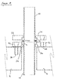
- the flange 20 is bolted onto the outer surface of the counterweight 4 and, to connect the exhaust pipe 18, the pipe is passed through the channel 17 and the hole 21 of the first flange.
- the collar 23 is then located in the gap between the pipe 18 and the flange 20, the collar 23 sitting on the recessed shoulder 22 of the flange 20, thereby holding the pipe in position but abutting the lipped end 19 of the pipe.
- the second flange 24 is then bolted to the first flange 20.
- the inventors have found that this provides an adequate seal between the two pipes, but if further sealing is required, a gasket or sealing ring may be interposed between the two flanges.
- Figures 8 and 9 illustrate, in cross-section and plan view respectively, a collar 23 for use in an exhaust system of the present invention.
- the collar is of generally circular construction and in two-part form.
- the collar has a generally L-shaped cross-section with its outer periphery 28 sized and shaped to abut with and sit on the recessed shoulder 22 of the first flange 20. Its inner periphery 29 defines a hole through which the lipped end 19 of the first pipe 18 may be passed.
- the collar 23 of this embodiment is of two-part construction such that the parts may be releasably placed around the first pipe 18 to secure within the flange 20.
- the collar 23 may be constructed as a single part, again having a generally L-shaped cross-section and of generally circular plan view.
- the collar 23 is fabricated from a deformable material and has a break at a point around its circumference, thereby allowing the collar 23 to be deformed to enable it to releasably encircle the exhaust pipe 18.
- Such a collar may be conveniently made of a plastics material such as nylon or PTFE. If a resiliently deformable material is used, this has the further advantage that the collar 23 may be deformed to pass it around an exhaust pipe 18, whereupon it will spring back to its at rest configuration. This prevents the risk of a two-part collar being dropped in the often busy and cramped environment in which such lift trucks operate.
- Figure 10 illustrates, in perspective view, a first flange 20 forming part of an exhaust pipe system according to the present invention, to more clearly illustrate its features.
- the flange has a central hole 21 to accommodate the lipped end 19 of an exhaust pipe, a recessed shoulder 22 surrounding the hole, and two sets of alternately spaced holes around the periphery of the flange.
- the first set of holes 25 each themselves have a recessed shoulder and are each configured to accommodate a bolt to allow the flange 20 to be bolted onto a counterweight 4.
- a second set of threaded holes 26 is provided to allow a second flange 24 to be attached.
- such a flange arrangement may be manufactured to be integral with a counterweight 4, by providing a recessed shoulder adjacent the channel 17 that penetrates the counterweight 4.
- FIG 11 illustrates, again in perspective view, an exhaust pipe forming part of an exhaust system of the present invention.
- the pipe 18 has a lip 19 protruding externally from the pipe 18.
- the lip 19 has the form of an extending flat rim around the pipe 18, in contrast to the flared embodiment illustrated in Figure 7 .
- the pipe 18 is also provided with a flexible section 30 allowing the pipe 18 to be manipulated such that its lipped end 19 may be passed through a channel 17 in a counterweight 4.
- a connector 31 At the other end of the pipe is a connector 31 to allow the pipe to be connected to an exhaust manifold.
- FIG 12 illustrates, in exploded perspective view, an exhaust system of the present invention.
- the system comprises a first pipe 18 for conveying exhaust from an engine (not illustrated).
- the pipe 18 is connected to an exhaust manifold by means of connector 31.
- the exhaust pipe 18 is again provided with a flexible section 30 to enable the pipe to be more readily manipulated.
- the end of the pipe distal from the engine is provided with an outwardly-projecting lip 19.
- the end of the exhaust pipe 18 is passed through the channel 17 in the counterweight form and through the hole in the first flange 20.
- the collar 23 is then located around the exhaust pipe 18 causing it to be held on the recessed shoulder of the first flange 20.
- a gasket 32 is provided, interposed between the first flange 20 and the second flange 24 attached to the tail pipe 5.
Landscapes
- Engineering & Computer Science (AREA)
- General Engineering & Computer Science (AREA)
- Mechanical Engineering (AREA)
- Chemical & Material Sciences (AREA)
- Combustion & Propulsion (AREA)
- Transportation (AREA)
- Structural Engineering (AREA)
- Civil Engineering (AREA)
- Life Sciences & Earth Sciences (AREA)
- Geology (AREA)
- Cooling, Air Intake And Gas Exhaust, And Fuel Tank Arrangements In Propulsion Units (AREA)
- Exhaust Silencers (AREA)
Description
- The invention relates to exhaust systems and couplings therefor, and especially to exhaust systems and couplings for use in counterweighted or armoured vehicles, especially counterweighted lift trucks and the like. The invention also relates to counterweights for such vehicles.
- Counterweighted lift trucks are widely used in industry, e.g. forklift trucks and other elevated platforms.
Figure 1 illustrates, in perspective view, a typical forklift truck 1 that may be used to move pallets in a warehouse environment. The forklift truck has a fork arrangement 2 at the front of the truck to engage with a pallet to be lifted and alifting mechanism 3 to enable the forks to be raised and lowered as required. In order to prevent the truck from toppling over when carrying a load on the forks, acounterbalance weight 4 is provided at the rear of the vehicle. Such counterbalance weights are often styled to resemble body panels, but in fact consist of a large block of dense material, such as cast iron. In many forklift truck systems, these counterweights may weigh anything up to 1-1.5 tonnes. In many such systems, and in order to further increase the counterbalance effect, the engine for the vehicle is located within a cavity behind thecounterweight 4. In effect, thecounterweight 4 is generally concave in construction, with the engine sitting partially within the envelope created by the counterweight. - For forklift trucks that use internal combustion engines, exhaust from the engine must be vented to atmosphere. Because such forklift trucks are often used in a confined environment, it is often necessary that the exhaust tail pipe 5 vents at a relatively high level on the vehicle. As a result, it is often required that the tail pipe 5 passes through the
counterweight 4. Such vehicles are often used in cramped environments, and it is common that the tailpipe 5 becomes damaged - especially when located in an elevated position - and needs to be replaced. This requires that the coupling between the exhaust tail pipe and the rest of the exhaust system is dismantled and reassembled to allow replacement. Due to the large mass of thecounterweight 4, it is not feasible to remove the counterweight to gain access to the engine compartment. As a result, the counterweights are often provided withaccess holes 6 through which limited access may be granted to the engine compartment and the exhaust coupling. -
Figures 2-4 illustrate typical exhaust couplings used in the industry.Figure 2 shows an arrangement in which two sections ofexhaust pipe 7, 8 may be joined by providing a slightly larger diameter end to one of the pipes 8, for example by flaring the end of the pipe, and by providing a slit 9 extending a short way along the axis of the pipe. In this way, onepipe 7 may be inserted into the end of the other pipe 8 and the two pipes clamped together by means of a circular clip (not illustrated). - Another pipe coupling which could be used for exhaust systems is shown in
DE 10 2005 061138 A1 . In Figure 3a this shows a coupling for a lipped pipe, having first and second flanges and also a further (tail) pipe. The coupling is relatively simple and the present invention improves on that coupling in order that it may be suitable for use with a counterweighted forklift truck having an internal combustion engine. -
Figure 3 illustrates another common alternative configuration, in cross-sectional view. In this system, the twopipes 7, 8 are provided with a flared or flanged end and the pipes are abutted against each other with an interposing sealing ring or gasket 10. Once assembled in this configuration, the pipes and gasket are held together by a circular clip 11 surrounding the assembly. Such a clip 11 is shown in plan view inFigure 4 comprising two arcuate portions 12, 13 connected at each end by fasteners 14 usually comprising a screw arrangement. - It will be appreciated that assembling and disassembling such couplings within the confined environment of the engine compartment such as a lift truck, where access is only available through
small access holes 6 is extremely difficult. Dexterity is required to manipulate the exhaust pipe couplings, which is ideally a two-handed operation, although the small access holes rarely allow both hands to be inserted into the engine compartment. As a result, significant downtime is often experienced when tail pipes need to be changed on lift trucks, thereby leading to operational difficulties and lost working time. - It is amongst the objects of the present invention to provide a solution to this and other problems. It will be appreciated that the solutions proposed are equally applicable to situations where exhaust pipes need to pass through armour plating, for example on military vehicles.
- Accordingly, the invention provides an exhaust system which comprises a first pipe for conveying exhaust from an engine, the end of said first pipe distal from the.engine having an outwardly protruding lip; a first pipe flange having a hole sufficiently large to allow the lipped end of the first pipe to pass therethrough; and a second pipe flange configured to attach to said first pipe flange to operably connect a tail pipe to said first pipe. Such an exhaust system is characterised in that the first pipe flange has a recess defining a shoulder around the hole therein, and in that there is a collar configured to releasably encircle said first pipe, to abut said shoulder at one end and abut the lipped end of said pipe at its other end, thereby preventing the collar and lipped pipe assembly from passing through said hole, and the second pipe flange serves to hold said first pipe, said first pipe flange and said collar assembly together.
- With such a system, the exhaust pipe from the exhaust manifold may be passed through a hole, or channel through a counterweight, or a heavily armoured section of an armoured vehicle, and located and temporarily secured in the first pipe flange by means of the collar, or locking ring. The assembly may then be secured by use of the second flange connecting a tail pipe to the exhaust pipe. In this way, assembly and disassembly of the exhaust system, for example to change the tailpipe may be performed requiring only minimal access to the engine compartment - elements of the assembly and disassembly process requiring manual dexterity are carried out outside the engine comportment itself.
- In a particular embodiment, the invention provides an exhaust system for a counterweighted lift truck comprising an exhaust system as described above wherein said first pipe flange comprises fixing points to affix it to a counterweight adjacent a channel passing through said counterweight such that the hole in said first pipe flange is substantially aligned with said channel.
- In any such embodiment, said collar comprises a plurality of collar sections, thereby allowing it to releasably encircle said pipe. For practical purposes, such a collar may be of two-part construction. However, more parts such as three or four would also function.
- In alternatively preferred embodiments said collar is formed of a deformable material, such as plastics, thereby allowing it to releasably encircle said pipe. More preferably, said deformable material is resiliently deformable. By use of a single-part deformable construction, the collar can be deformed to encircle the pipe, for example by twisting the collar. The collar can then he returned to an encircling configuration; when a resiliently deformable material is used, the collar will automatically spring back to its encircling configuration, thereby allowing the operation to be carried out with a single hand, leaving the other hand free to steady or hold the exhaust pipe.
- In any such system, the system preferably further comprises a gasket interposed between said first pipe and said tail pipe.
- Also in any aspect of the invention, it is preferred that said first pipe further comprises a flexible coupling between the engine and said lipped end. In this way, manipulation of the lipped end of the exhaust pipe to pass it through the counterweight is facilitated.
- When the system is used with a counterweighted lift truck, then in preferred embodiments, said pipe flange is integral with said counterweight. Where the channel through the counterweight exists at the external surface of the counterweight, a mating surface is provided around the channel, in addition to a recessed shoulder within the channel, to accept the lipped end of the exhaust pipe and a collar surrounding it, thereby locating and holding the lipped end on the recessed shoulder.
- The invention also provides an exhaust system including a counterweight for a counterweighted lift truck comprising a channel passing through said counterweight, so sized as to allow an exhaust pipe to pass through it, said counterweight having fixing points adjacent said channel configured to join said counterweight to an exhaust pipe flange.
- The invention further provides an exhaust system including a counterweight for a counterweighted lift truck comprising a channel passing through said counterweight, so sized as to allow an exhaust pipe to pass through it, a recessed shoulder and flange mating surface adjacent said channel and fixing points on the external surface of said counterweight disposed about and adjacent said channel to allow the connection of a flange.
- Also included within the scope of the invention is a method of fitting an exhaust system to a counterweighted lift truck comprising the steps of: providing a counterweight having a channel passing through it; providing an exhaust pipe for conveying exhaust from an engine, said exhaust pipe having an outwardly-protruding lip at an end distal from said engine; passing said exhaust pipe through said channel; fitting a collar around said exhaust pipe to engage with said lip; engaging said collar with recessed shoulder in a first pipe flange attached to said counterweight adjacent said channel; operably connecting a tailpipe to said exhaust pipe with a second flange, said second flange acting to hold said pipe, flange and collar assembly together. Preferably, said first pipe flange is integral with said counterweight.
- Also included within the scope of the invention is an exhaust system substantially as described herein, with reference to and as illustrated by an appropriate combination of
Figures 5-12 . - The invention will be described with reference to the accompanying drawings in which:
-
Figure 1 is a perspective illustration of a counterweighted lift truck; -
Figures 2-3 illustrate known exhaust pipe coupling systems; -
Figures 5 and 6 illustrate, in perspective view, counterweights for a counterweighted lift truck; -
Figure 7 illustrates, in exploded perspective view, an exhaust system of the present invention; -
Figures 8 and 9 illustrate in cross-section and plan view respectively, a collar forming part of an exhaust system of the present invention; -
Figure 10 illustrates, in perspective view, a first pipe flange forming part of an exhaust system of the present invention; -
Figure 11 illustrates, in perspective view a first pipe forming part of an exhaust system of the present invention; and -
Figure 12 illustrates, in exploded perspective view, an exhaust system according to the present invention. -
Figures 5 and 6 illustrate, in perspective view,typical counterweights 4 that might be used in a counterweighted lift truck. As can be seen, the counterweights are of a generally solid construction, and are typically made of cast iron. The counterweights have a generallyconcave side 15 forming part of the shell of the engine compartment, and a generally convexexterior side 16 forming the outside of the vehicle. Access holes 6 are provided affording limited access to the engine compartment. - An
exhaust pipe channel 17 is provided, extending between theexterior face 16 andinterior face 15 of thecounterweight 4. -
Figure 7 illustrates, in exploded perspective view, an exhaust system according to the present invention. The system comprises afirst pipe 18 for conveying exhaust from an engine (not illustrated). The end of thispipe 18 distal from the engine has alip 19 protruding outwardly from thepipe 18. Afirst pipe flange 20 has ahole 21 large enough to allow thelipped end 18 of the pipe to pass through it. Theflange 20 also has, adjacent thehole 21, a recessed shoulder 22. Also provided is a collar, or lockingring 23. In this embodiment, thecollar 23 is of two-part construction having a generally L-shaped cross-section and so sized and shaped such that its outer periphery will sit on, and abut the recessed shoulder 22 of theflange 20, and its inner periphery will abut thelipped end 19 of thefirst pipe 18 once the unit is assembled. - There is also provided a
second pipe flange 24 configured to attach to thefirst pipe flange 20 to operably connect a tail pipe 5 to thefirst pipe 18 and to hold the pipe flange and collar assembly together. - In this embodiment, the
flange 20 is provided with two sets of holes, alternately spaced around the periphery of theflange 20. Thefirst set 25 allow theflange 20 to be bolted to acounterweight 4, and the second set ofholes 26, here provided with an internal thread, allow connection with thesecond flange 24. - Referring back to
Figures 5 and 6 , we see that surrounding thechannel 17 is a mating surface provided with three threadedholes 27 to allow the connection of thefirst flange 20 to the outer surface of thecounterweight 4 such that thehole 21 in the first pipe flange is substantially aligned with thechannel 17. - In use, the
flange 20 is bolted onto the outer surface of thecounterweight 4 and, to connect theexhaust pipe 18, the pipe is passed through thechannel 17 and thehole 21 of the first flange. Thecollar 23 is then located in the gap between thepipe 18 and theflange 20, thecollar 23 sitting on the recessed shoulder 22 of theflange 20, thereby holding the pipe in position but abutting thelipped end 19 of the pipe. To secure the assembly, thesecond flange 24 is then bolted to thefirst flange 20. The inventors have found that this provides an adequate seal between the two pipes, but if further sealing is required, a gasket or sealing ring may be interposed between the two flanges. - In this way, assembly and disassembly of the exhaust pipe coupling may readily be made without having to manipulate pipe clips such as those illustrated in
Figure 4 within the confined space of the engine cavity. -
Figures 8 and 9 illustrate, in cross-section and plan view respectively, acollar 23 for use in an exhaust system of the present invention. The collar is of generally circular construction and in two-part form. The collar has a generally L-shaped cross-section with itsouter periphery 28 sized and shaped to abut with and sit on the recessed shoulder 22 of thefirst flange 20. Itsinner periphery 29 defines a hole through which thelipped end 19 of thefirst pipe 18 may be passed. - It will be appreciated that the
collar 23 of this embodiment is of two-part construction such that the parts may be releasably placed around thefirst pipe 18 to secure within theflange 20. - In alternative configurations, the
collar 23 may be constructed as a single part, again having a generally L-shaped cross-section and of generally circular plan view. In such a configuration, thecollar 23 is fabricated from a deformable material and has a break at a point around its circumference, thereby allowing thecollar 23 to be deformed to enable it to releasably encircle theexhaust pipe 18. Such a collar may be conveniently made of a plastics material such as nylon or PTFE. If a resiliently deformable material is used, this has the further advantage that thecollar 23 may be deformed to pass it around anexhaust pipe 18, whereupon it will spring back to its at rest configuration. This prevents the risk of a two-part collar being dropped in the often busy and cramped environment in which such lift trucks operate. -
Figure 10 illustrates, in perspective view, afirst flange 20 forming part of an exhaust pipe system according to the present invention, to more clearly illustrate its features. The flange has acentral hole 21 to accommodate thelipped end 19 of an exhaust pipe, a recessed shoulder 22 surrounding the hole, and two sets of alternately spaced holes around the periphery of the flange. The first set ofholes 25 each themselves have a recessed shoulder and are each configured to accommodate a bolt to allow theflange 20 to be bolted onto acounterweight 4. A second set of threadedholes 26 is provided to allow asecond flange 24 to be attached. - It will be appreciated that, in alternative embodiments of the invention, such a flange arrangement may be manufactured to be integral with a
counterweight 4, by providing a recessed shoulder adjacent thechannel 17 that penetrates thecounterweight 4. -
Figure 11 illustrates, again in perspective view, an exhaust pipe forming part of an exhaust system of the present invention. Thepipe 18 has alip 19 protruding externally from thepipe 18. In this embodiment, thelip 19 has the form of an extending flat rim around thepipe 18, in contrast to the flared embodiment illustrated inFigure 7 . In this embodiment, thepipe 18 is also provided with aflexible section 30 allowing thepipe 18 to be manipulated such that itslipped end 19 may be passed through achannel 17 in acounterweight 4. At the other end of the pipe is aconnector 31 to allow the pipe to be connected to an exhaust manifold. -
Figure 12 illustrates, in exploded perspective view, an exhaust system of the present invention. The system comprises afirst pipe 18 for conveying exhaust from an engine (not illustrated). Thepipe 18 is connected to an exhaust manifold by means ofconnector 31. Theexhaust pipe 18 is again provided with aflexible section 30 to enable the pipe to be more readily manipulated. The end of the pipe distal from the engine is provided with an outwardly-projectinglip 19. The end of theexhaust pipe 18 is passed through thechannel 17 in the counterweight form and through the hole in thefirst flange 20. Thecollar 23 is then located around theexhaust pipe 18 causing it to be held on the recessed shoulder of thefirst flange 20. In this embodiment, agasket 32 is provided, interposed between thefirst flange 20 and thesecond flange 24 attached to the tail pipe 5.
Claims (12)
- An exhaust system comprising:a first pipe (18) for conveying exhaust from an engine, the end of said first pipe distal from the engine having an outwardly protruding lip (19);a first pipe flange (20) having a hole (21) sufficiently large to allow the lipped end of the first pipe (18) to pass therethrough; anda second pipe flange (24) configured to attach to said first pipe flange (20) to operably connect a tail pipe (5) to said first pipe (18); characterised in that: the first pipe flange has a recess defining a shoulder (22) around the hole (21) therein; and in that there is a collar (23) configured to releasably encircle said first pipe (18), to abut said shoulder (22) at one end and abut the lipped end of said pipe at its other end, thereby preventing the collar and lipped pipe assembly from passing through said hole; and the second pipe flange (24) serves to hold said first pipe (18), said first pipe flange (20) and said collar (23) assembly together.
- An exhaust system according to claim 1, wherein said collar (23) comprises a plurality of collar sections, thereby allowing the collar to releasably encircle said first pipe (18).
- An exhaust system according to claim 1, wherein said collar (23) is formed of a deformable material, thereby allowing the collar to releasably encircle said first pipe (18).
- An exhaust system according to claim 3, wherein said deformable material is resiliently deformable.
- An exhaust system according to claim 3 or claim 4, wherein said collar is formed of a resiliently deformable plastics material.
- An exhaust system according to any of the preceding claims, further comprising a gasket (32) interposed between said first pipe (18) and said tail pipe (5).
- An exhaust system according to any of the preceding claims, wherein said first pipe (18) further comprises a flexible coupling (30) disposed between the end of the pipe proximal the engine and the lipped end of the pipe.
- An exhaust system according to any of the preceding claims in combination with a counterweight (4) for a lift truck (1) and having a channel extending therethrough, wherein the first pipe flange (20) includes fixing holes (26) by means of which said first pipe flange is affixed to the counterweight with the hole (21) in said first pipe flange (20) substantially aligned with the channel (17).
- An exhaust system according to any of claims 1 to 7 in combination with a counterweight (4) for a lift truck (1) and having a channel extending therethrough, wherein said first pipe flange (20) is integral with said counterweight (4).
- An exhaust system according to claim 8 or claim 9, wherein the channel (17) passing through said counterweight (4) sized to allow the first pipe (18) to pass therethrough, the counterweight (4) having fixing points (27) around said channel configured to allow said first pipe flange (20) to be joined to the counterweight.
- An exhaust system according to claim 8 or claim 9, wherein there is a channel (17) passing through said counterweight (4) sized to allow the first pipe (18) to pass therethrough, and the first pipe flange (20) is formed integrally with the counterweight (4) and defines a recessed shoulder (22) is formed in the counterweight around the channel (17), the counterweight having formed therein fixing points (27) for attachment of the second pipe flange (24) to the counterweight.
- A method of fitting an exhaust system to a counterweighted lift truck comprising the steps of:providing a counterweight (4) having a channel (17) passing therethrough;providing an exhaust pipe (18) for conveying exhaust from an engine, said exhaust pipe having an outwardly-protruding lip (19) at an end distal from said engine;passing said exhaust pipe (18) through said channel (17);fitting a collar (23) around said exhaust pipe (18) to engage with said lip (19);engaging said collar (23) with a recessed shoulder (22) in a first pipe flange (20) attached to or integral with the counterweight (4), so that a hole (21) in the flange is aligned with the channel (17); andoperably connecting a tailpipe (5) to said exhaust pipe (18) with a second flange (24), said second flange acting to hold said exhaust pipe (18), first pipe flange (20) and collar (23) assembly together.
Applications Claiming Priority (3)
| Application Number | Priority Date | Filing Date | Title |
|---|---|---|---|
| GBGB1004035.0A GB201004035D0 (en) | 2010-03-11 | 2010-03-11 | A coupling |
| GB1006044.0A GB2478607B (en) | 2010-03-11 | 2010-04-12 | A coupling |
| PCT/GB2011/050465 WO2011110851A1 (en) | 2010-03-11 | 2011-03-09 | A coupling |
Publications (2)
| Publication Number | Publication Date |
|---|---|
| EP2545264A1 EP2545264A1 (en) | 2013-01-16 |
| EP2545264B1 true EP2545264B1 (en) | 2014-08-20 |
Family
ID=42236155
Family Applications (1)
| Application Number | Title | Priority Date | Filing Date |
|---|---|---|---|
| EP11709791.5A Not-in-force EP2545264B1 (en) | 2010-03-11 | 2011-03-09 | A coupling |
Country Status (4)
| Country | Link |
|---|---|
| US (1) | US10316729B2 (en) |
| EP (1) | EP2545264B1 (en) |
| GB (2) | GB201004035D0 (en) |
| WO (1) | WO2011110851A1 (en) |
Families Citing this family (10)
| Publication number | Priority date | Publication date | Assignee | Title |
|---|---|---|---|---|
| FR2976041B1 (en) * | 2011-05-30 | 2014-07-25 | Ensival Moret France | CONNECTING FLANGE OF A HYDRAULIC OR PNEUMATIC PIPING OF AN INDUSTRIAL MACHINE |
| DE102011112633B4 (en) * | 2011-09-05 | 2015-06-11 | Faurecia Emissions Control Technologies, Germany Gmbh | Exhaust pipe assembly and method for attaching a mounting plate to an exhaust pipe |
| JP5731426B2 (en) * | 2012-02-28 | 2015-06-10 | 日立建機株式会社 | Work machine |
| JP6242626B2 (en) * | 2013-08-09 | 2017-12-06 | コスモ工機株式会社 | Pipe fitting |
| EP2896864A1 (en) * | 2014-01-21 | 2015-07-22 | Siemens Aktiengesellschaft | Connection system |
| DE102016014659A1 (en) * | 2016-12-09 | 2018-06-14 | Liebherr-Hydraulikbagger Gmbh | Working machine with a ballast device |
| JP6592487B2 (en) * | 2017-09-28 | 2019-10-16 | コスモ工機株式会社 | Pipe fitting |
| JP6914302B2 (en) * | 2017-09-28 | 2021-08-04 | コスモ工機株式会社 | Pipe fitting |
| US11598456B1 (en) * | 2021-08-12 | 2023-03-07 | Freudenberg Oil & Gas, Llc | Pipe connection with split swivel ring |
| US11821348B1 (en) * | 2022-08-01 | 2023-11-21 | Cummins Emission Solutions Inc. | Systems and methods for mounting an aftertreament system component |
Family Cites Families (26)
| Publication number | Priority date | Publication date | Assignee | Title |
|---|---|---|---|---|
| US459907A (en) * | 1891-09-22 | John j | ||
| US1186325A (en) * | 1915-07-27 | 1916-06-06 | Leslie Company | Coupling. |
| US1820020A (en) * | 1928-11-26 | 1931-08-25 | Westinghouse Air Brake Co | Pipe coupling |
| US2264512A (en) * | 1939-04-14 | 1941-12-02 | Clark Equipment Co | Industrial truck |
| US2561300A (en) * | 1948-09-24 | 1951-07-17 | Coventry Climax Eng Ltd | Industrial truck |
| US2768847A (en) * | 1950-07-19 | 1956-10-30 | Neyrpic Ets | Flange retained key drive type of mechanical coupling |
| US2688500A (en) * | 1952-01-02 | 1954-09-07 | Laval Separator Co De | Coupling for pipes |
| US2880020A (en) * | 1955-10-12 | 1959-03-31 | Richard R Audette | Hose coupling with wedge hose gripping means |
| US3787086A (en) * | 1970-05-05 | 1974-01-22 | Clark Equipment Co | Adjustable seat for an industrial vehicle |
| FR2398249B1 (en) * | 1977-07-18 | 1981-11-27 | Boyer Jean Jacques | |
| GB1595648A (en) * | 1978-05-24 | 1981-08-12 | Hedins Mek Verkstad Ab | Flange coupling |
| CH643341A5 (en) * | 1980-04-09 | 1984-05-30 | Fischer Ag Georg | FLANGE CONNECTION. |
| JPS5839522A (en) * | 1981-09-03 | 1983-03-08 | Nissan Motor Co Ltd | Installation structure of overhead exhaust muffler of forklift |
| US4448448A (en) * | 1982-03-22 | 1984-05-15 | Raphael Theresa Pollia | Coupling system |
| FR2545187B1 (en) * | 1983-04-27 | 1985-07-05 | Commissariat Energie Atomique | WATERPROOF CONNECTION DEVICE |
| DE8714673U1 (en) * | 1987-11-04 | 1988-02-04 | Ringsdorff-Werke GmbH, 5300 Bonn | Sealing ring for exhaust pipe |
| DE19508023A1 (en) * | 1995-03-07 | 1996-09-12 | Dietzel Hydraulik | Pipe bend with at least one connecting piece |
| US6079753A (en) * | 1996-03-12 | 2000-06-27 | Erwin's Llc | Segmented flange including a shim |
| JP2001050447A (en) * | 1999-08-06 | 2001-02-23 | Toyota Autom Loom Works Ltd | Detachable pipe |
| US6331020B1 (en) * | 1999-08-23 | 2001-12-18 | Pacific Flo-Rite, Inc. | Coupling for flex pipe, rigid pipe and flexible hose |
| JP2001248438A (en) * | 2000-03-07 | 2001-09-14 | Komatsu Forklift Co Ltd | Height adjustable upward muffler |
| US6460901B2 (en) * | 2001-02-13 | 2002-10-08 | Alpha-Western Corporation | Split thread nut assembly |
| JP4076372B2 (en) * | 2002-05-27 | 2008-04-16 | 臼井国際産業株式会社 | Flange piping connection structure |
| DE102005061138A1 (en) | 2005-12-21 | 2007-08-09 | Audi Ag | Exhaust gas system for motor vehicle, has coupling unit designed as repair flange halves that together with spare part flange halves form pipe coupling, where repair and spare part flange halves are permeated by common connection unit |
| DE102008010629A1 (en) * | 2008-02-22 | 2009-09-03 | Daimler Ag | Flange for piping of exhaust system of motor vehicle i.e. truck, has attachment openings provided for corresponding pins to attach flange with another flange, and recesses extending between assigned opening and outer side of flange |
| WO2010071380A2 (en) * | 2008-12-19 | 2010-06-24 | 두산인프라코어 주식회사 | Low maintenance counter weight structure for heavy equipment |
-
2010
- 2010-03-11 GB GBGB1004035.0A patent/GB201004035D0/en not_active Ceased
- 2010-04-12 GB GB1006044.0A patent/GB2478607B/en not_active Expired - Fee Related
-
2011
- 2011-03-09 WO PCT/GB2011/050465 patent/WO2011110851A1/en not_active Ceased
- 2011-03-09 EP EP11709791.5A patent/EP2545264B1/en not_active Not-in-force
- 2011-03-09 US US13/634,007 patent/US10316729B2/en not_active Expired - Fee Related
Also Published As
| Publication number | Publication date |
|---|---|
| GB201006044D0 (en) | 2010-05-26 |
| GB201004035D0 (en) | 2010-04-28 |
| US20130127157A1 (en) | 2013-05-23 |
| GB2478607A (en) | 2011-09-14 |
| EP2545264A1 (en) | 2013-01-16 |
| WO2011110851A1 (en) | 2011-09-15 |
| GB2478607B (en) | 2012-05-16 |
| US10316729B2 (en) | 2019-06-11 |
Similar Documents
| Publication | Publication Date | Title |
|---|---|---|
| US10316729B2 (en) | Coupling | |
| US6076864A (en) | Flange for compensator couplings or pipes | |
| US5779285A (en) | Pipe coupling assembly | |
| EP1481184B1 (en) | Pipe coupler | |
| US5711549A (en) | High pressure quick connect for use in automotive brake system application | |
| US9310083B2 (en) | Combustion chamber for an aircraft engine, and method for attaching an injection system in a combustion chamber of an aircraft engine | |
| EP2952727B1 (en) | Valve for fuel supply system | |
| EP3036407B1 (en) | Vane arm assembly | |
| US8529358B2 (en) | Rotational coupling and driving assembly | |
| EP3511604A1 (en) | Modular split sleeve | |
| GB2489333A (en) | A Counterweight | |
| US20030073500A1 (en) | Elastic coupling | |
| KR20140110048A (en) | Exhaust turbocharger | |
| US20140125057A1 (en) | Flange for connecting a hydraulic or pneumatic pipe of an industrial machine | |
| US10520084B2 (en) | Metal bellows | |
| US20180347440A1 (en) | Exhaust system support structure | |
| CN103062508A (en) | Abnormal-shaped nut type floating sealing structure used for penetrating through cartridge receiver | |
| US11707851B2 (en) | Arm-shaped structure body and robot | |
| US7469937B2 (en) | Quick connecting device for ducts in motor vehicles | |
| US10598211B2 (en) | Spherical bearing sleeve configured with one or more discrete collars | |
| EP2938915B1 (en) | Sealing element and arrangement | |
| MX2012007609A (en) | End member assembly, gas spring assembly and method. | |
| US20210355855A1 (en) | Heat insulating cover for exhaust device | |
| EP1267049A1 (en) | Improved toroidal gasket for exhaust pipes | |
| US20200271254A1 (en) | Thermoplastic flange with overmolded metal plate |
Legal Events
| Date | Code | Title | Description |
|---|---|---|---|
| PUAI | Public reference made under article 153(3) epc to a published international application that has entered the european phase |
Free format text: ORIGINAL CODE: 0009012 |
|
| 17P | Request for examination filed |
Effective date: 20121011 |
|
| AK | Designated contracting states |
Kind code of ref document: A1 Designated state(s): AL AT BE BG CH CY CZ DE DK EE ES FI FR GB GR HR HU IE IS IT LI LT LU LV MC MK MT NL NO PL PT RO RS SE SI SK SM TR |
|
| DAX | Request for extension of the european patent (deleted) | ||
| REG | Reference to a national code |
Ref country code: DE Ref legal event code: R079 Ref document number: 602011009266 Country of ref document: DE Free format text: PREVIOUS MAIN CLASS: F01N0013180000 Ipc: F16L0023032000 |
|
| RIC1 | Information provided on ipc code assigned before grant |
Ipc: B60K 13/04 20060101ALI20130801BHEP Ipc: F16L 23/028 20060101ALI20130801BHEP Ipc: B66F 9/075 20060101ALI20130801BHEP Ipc: F16L 23/032 20060101AFI20130801BHEP Ipc: F01N 13/18 20100101ALI20130801BHEP |
|
| GRAP | Despatch of communication of intention to grant a patent |
Free format text: ORIGINAL CODE: EPIDOSNIGR1 |
|
| INTG | Intention to grant announced |
Effective date: 20130913 |
|
| GRAS | Grant fee paid |
Free format text: ORIGINAL CODE: EPIDOSNIGR3 |
|
| GRAA | (expected) grant |
Free format text: ORIGINAL CODE: 0009210 |
|
| AK | Designated contracting states |
Kind code of ref document: B1 Designated state(s): AL AT BE BG CH CY CZ DE DK EE ES FI FR GB GR HR HU IE IS IT LI LT LU LV MC MK MT NL NO PL PT RO RS SE SI SK SM TR |
|
| REG | Reference to a national code |
Ref country code: GB Ref legal event code: FG4D |
|
| REG | Reference to a national code |
Ref country code: CH Ref legal event code: EP |
|
| REG | Reference to a national code |
Ref country code: AT Ref legal event code: REF Ref document number: 683665 Country of ref document: AT Kind code of ref document: T Effective date: 20140915 |
|
| REG | Reference to a national code |
Ref country code: IE Ref legal event code: FG4D |
|
| REG | Reference to a national code |
Ref country code: DE Ref legal event code: R096 Ref document number: 602011009266 Country of ref document: DE Effective date: 20141002 |
|
| REG | Reference to a national code |
Ref country code: NL Ref legal event code: T3 |
|
| REG | Reference to a national code |
Ref country code: AT Ref legal event code: MK05 Ref document number: 683665 Country of ref document: AT Kind code of ref document: T Effective date: 20140820 |
|
| REG | Reference to a national code |
Ref country code: LT Ref legal event code: MG4D |
|
| PG25 | Lapsed in a contracting state [announced via postgrant information from national office to epo] |
Ref country code: PT Free format text: LAPSE BECAUSE OF FAILURE TO SUBMIT A TRANSLATION OF THE DESCRIPTION OR TO PAY THE FEE WITHIN THE PRESCRIBED TIME-LIMIT Effective date: 20141222 Ref country code: LT Free format text: LAPSE BECAUSE OF FAILURE TO SUBMIT A TRANSLATION OF THE DESCRIPTION OR TO PAY THE FEE WITHIN THE PRESCRIBED TIME-LIMIT Effective date: 20140820 Ref country code: BG Free format text: LAPSE BECAUSE OF FAILURE TO SUBMIT A TRANSLATION OF THE DESCRIPTION OR TO PAY THE FEE WITHIN THE PRESCRIBED TIME-LIMIT Effective date: 20141120 Ref country code: FI Free format text: LAPSE BECAUSE OF FAILURE TO SUBMIT A TRANSLATION OF THE DESCRIPTION OR TO PAY THE FEE WITHIN THE PRESCRIBED TIME-LIMIT Effective date: 20140820 Ref country code: SE Free format text: LAPSE BECAUSE OF FAILURE TO SUBMIT A TRANSLATION OF THE DESCRIPTION OR TO PAY THE FEE WITHIN THE PRESCRIBED TIME-LIMIT Effective date: 20140820 Ref country code: GR Free format text: LAPSE BECAUSE OF FAILURE TO SUBMIT A TRANSLATION OF THE DESCRIPTION OR TO PAY THE FEE WITHIN THE PRESCRIBED TIME-LIMIT Effective date: 20141121 Ref country code: ES Free format text: LAPSE BECAUSE OF FAILURE TO SUBMIT A TRANSLATION OF THE DESCRIPTION OR TO PAY THE FEE WITHIN THE PRESCRIBED TIME-LIMIT Effective date: 20140820 Ref country code: NO Free format text: LAPSE BECAUSE OF FAILURE TO SUBMIT A TRANSLATION OF THE DESCRIPTION OR TO PAY THE FEE WITHIN THE PRESCRIBED TIME-LIMIT Effective date: 20141120 |
|
| PG25 | Lapsed in a contracting state [announced via postgrant information from national office to epo] |
Ref country code: HR Free format text: LAPSE BECAUSE OF FAILURE TO SUBMIT A TRANSLATION OF THE DESCRIPTION OR TO PAY THE FEE WITHIN THE PRESCRIBED TIME-LIMIT Effective date: 20140820 Ref country code: LV Free format text: LAPSE BECAUSE OF FAILURE TO SUBMIT A TRANSLATION OF THE DESCRIPTION OR TO PAY THE FEE WITHIN THE PRESCRIBED TIME-LIMIT Effective date: 20140820 Ref country code: IS Free format text: LAPSE BECAUSE OF FAILURE TO SUBMIT A TRANSLATION OF THE DESCRIPTION OR TO PAY THE FEE WITHIN THE PRESCRIBED TIME-LIMIT Effective date: 20141220 Ref country code: AT Free format text: LAPSE BECAUSE OF FAILURE TO SUBMIT A TRANSLATION OF THE DESCRIPTION OR TO PAY THE FEE WITHIN THE PRESCRIBED TIME-LIMIT Effective date: 20140820 Ref country code: RS Free format text: LAPSE BECAUSE OF FAILURE TO SUBMIT A TRANSLATION OF THE DESCRIPTION OR TO PAY THE FEE WITHIN THE PRESCRIBED TIME-LIMIT Effective date: 20140820 |
|
| PG25 | Lapsed in a contracting state [announced via postgrant information from national office to epo] |
Ref country code: EE Free format text: LAPSE BECAUSE OF FAILURE TO SUBMIT A TRANSLATION OF THE DESCRIPTION OR TO PAY THE FEE WITHIN THE PRESCRIBED TIME-LIMIT Effective date: 20140820 Ref country code: CZ Free format text: LAPSE BECAUSE OF FAILURE TO SUBMIT A TRANSLATION OF THE DESCRIPTION OR TO PAY THE FEE WITHIN THE PRESCRIBED TIME-LIMIT Effective date: 20140820 Ref country code: IT Free format text: LAPSE BECAUSE OF FAILURE TO SUBMIT A TRANSLATION OF THE DESCRIPTION OR TO PAY THE FEE WITHIN THE PRESCRIBED TIME-LIMIT Effective date: 20140820 Ref country code: SK Free format text: LAPSE BECAUSE OF FAILURE TO SUBMIT A TRANSLATION OF THE DESCRIPTION OR TO PAY THE FEE WITHIN THE PRESCRIBED TIME-LIMIT Effective date: 20140820 Ref country code: RO Free format text: LAPSE BECAUSE OF FAILURE TO SUBMIT A TRANSLATION OF THE DESCRIPTION OR TO PAY THE FEE WITHIN THE PRESCRIBED TIME-LIMIT Effective date: 20140820 Ref country code: DK Free format text: LAPSE BECAUSE OF FAILURE TO SUBMIT A TRANSLATION OF THE DESCRIPTION OR TO PAY THE FEE WITHIN THE PRESCRIBED TIME-LIMIT Effective date: 20140820 |
|
| REG | Reference to a national code |
Ref country code: DE Ref legal event code: R097 Ref document number: 602011009266 Country of ref document: DE |
|
| PG25 | Lapsed in a contracting state [announced via postgrant information from national office to epo] |
Ref country code: PL Free format text: LAPSE BECAUSE OF FAILURE TO SUBMIT A TRANSLATION OF THE DESCRIPTION OR TO PAY THE FEE WITHIN THE PRESCRIBED TIME-LIMIT Effective date: 20140820 |
|
| PLBE | No opposition filed within time limit |
Free format text: ORIGINAL CODE: 0009261 |
|
| STAA | Information on the status of an ep patent application or granted ep patent |
Free format text: STATUS: NO OPPOSITION FILED WITHIN TIME LIMIT |
|
| 26N | No opposition filed |
Effective date: 20150521 |
|
| PG25 | Lapsed in a contracting state [announced via postgrant information from national office to epo] |
Ref country code: LU Free format text: LAPSE BECAUSE OF FAILURE TO SUBMIT A TRANSLATION OF THE DESCRIPTION OR TO PAY THE FEE WITHIN THE PRESCRIBED TIME-LIMIT Effective date: 20150309 Ref country code: MC Free format text: LAPSE BECAUSE OF FAILURE TO SUBMIT A TRANSLATION OF THE DESCRIPTION OR TO PAY THE FEE WITHIN THE PRESCRIBED TIME-LIMIT Effective date: 20140820 |
|
| REG | Reference to a national code |
Ref country code: CH Ref legal event code: PL |
|
| PG25 | Lapsed in a contracting state [announced via postgrant information from national office to epo] |
Ref country code: SI Free format text: LAPSE BECAUSE OF FAILURE TO SUBMIT A TRANSLATION OF THE DESCRIPTION OR TO PAY THE FEE WITHIN THE PRESCRIBED TIME-LIMIT Effective date: 20140820 |
|
| REG | Reference to a national code |
Ref country code: IE Ref legal event code: MM4A |
|
| PG25 | Lapsed in a contracting state [announced via postgrant information from national office to epo] |
Ref country code: CH Free format text: LAPSE BECAUSE OF NON-PAYMENT OF DUE FEES Effective date: 20150331 Ref country code: LI Free format text: LAPSE BECAUSE OF NON-PAYMENT OF DUE FEES Effective date: 20150331 Ref country code: IE Free format text: LAPSE BECAUSE OF NON-PAYMENT OF DUE FEES Effective date: 20150309 |
|
| REG | Reference to a national code |
Ref country code: FR Ref legal event code: PLFP Year of fee payment: 6 |
|
| PG25 | Lapsed in a contracting state [announced via postgrant information from national office to epo] |
Ref country code: BE Free format text: LAPSE BECAUSE OF FAILURE TO SUBMIT A TRANSLATION OF THE DESCRIPTION OR TO PAY THE FEE WITHIN THE PRESCRIBED TIME-LIMIT Effective date: 20140820 |
|
| PG25 | Lapsed in a contracting state [announced via postgrant information from national office to epo] |
Ref country code: MT Free format text: LAPSE BECAUSE OF FAILURE TO SUBMIT A TRANSLATION OF THE DESCRIPTION OR TO PAY THE FEE WITHIN THE PRESCRIBED TIME-LIMIT Effective date: 20140820 |
|
| REG | Reference to a national code |
Ref country code: FR Ref legal event code: PLFP Year of fee payment: 7 |
|
| PG25 | Lapsed in a contracting state [announced via postgrant information from national office to epo] |
Ref country code: SM Free format text: LAPSE BECAUSE OF FAILURE TO SUBMIT A TRANSLATION OF THE DESCRIPTION OR TO PAY THE FEE WITHIN THE PRESCRIBED TIME-LIMIT Effective date: 20140820 Ref country code: HU Free format text: LAPSE BECAUSE OF FAILURE TO SUBMIT A TRANSLATION OF THE DESCRIPTION OR TO PAY THE FEE WITHIN THE PRESCRIBED TIME-LIMIT; INVALID AB INITIO Effective date: 20110309 |
|
| PG25 | Lapsed in a contracting state [announced via postgrant information from national office to epo] |
Ref country code: CY Free format text: LAPSE BECAUSE OF FAILURE TO SUBMIT A TRANSLATION OF THE DESCRIPTION OR TO PAY THE FEE WITHIN THE PRESCRIBED TIME-LIMIT Effective date: 20140820 |
|
| PG25 | Lapsed in a contracting state [announced via postgrant information from national office to epo] |
Ref country code: TR Free format text: LAPSE BECAUSE OF FAILURE TO SUBMIT A TRANSLATION OF THE DESCRIPTION OR TO PAY THE FEE WITHIN THE PRESCRIBED TIME-LIMIT Effective date: 20140820 |
|
| REG | Reference to a national code |
Ref country code: FR Ref legal event code: PLFP Year of fee payment: 8 |
|
| PG25 | Lapsed in a contracting state [announced via postgrant information from national office to epo] |
Ref country code: MK Free format text: LAPSE BECAUSE OF FAILURE TO SUBMIT A TRANSLATION OF THE DESCRIPTION OR TO PAY THE FEE WITHIN THE PRESCRIBED TIME-LIMIT Effective date: 20140820 |
|
| PG25 | Lapsed in a contracting state [announced via postgrant information from national office to epo] |
Ref country code: AL Free format text: LAPSE BECAUSE OF FAILURE TO SUBMIT A TRANSLATION OF THE DESCRIPTION OR TO PAY THE FEE WITHIN THE PRESCRIBED TIME-LIMIT Effective date: 20140820 |
|
| PGFP | Annual fee paid to national office [announced via postgrant information from national office to epo] |
Ref country code: DE Payment date: 20190331 Year of fee payment: 9 |
|
| PGFP | Annual fee paid to national office [announced via postgrant information from national office to epo] |
Ref country code: FR Payment date: 20190205 Year of fee payment: 9 Ref country code: NL Payment date: 20190307 Year of fee payment: 9 |
|
| PGFP | Annual fee paid to national office [announced via postgrant information from national office to epo] |
Ref country code: GB Payment date: 20200312 Year of fee payment: 10 |
|
| REG | Reference to a national code |
Ref country code: DE Ref legal event code: R119 Ref document number: 602011009266 Country of ref document: DE |
|
| REG | Reference to a national code |
Ref country code: NL Ref legal event code: MM Effective date: 20200401 |
|
| PG25 | Lapsed in a contracting state [announced via postgrant information from national office to epo] |
Ref country code: NL Free format text: LAPSE BECAUSE OF NON-PAYMENT OF DUE FEES Effective date: 20200401 |
|
| PG25 | Lapsed in a contracting state [announced via postgrant information from national office to epo] |
Ref country code: DE Free format text: LAPSE BECAUSE OF NON-PAYMENT OF DUE FEES Effective date: 20201001 Ref country code: FR Free format text: LAPSE BECAUSE OF NON-PAYMENT OF DUE FEES Effective date: 20200331 |
|
| GBPC | Gb: european patent ceased through non-payment of renewal fee |
Effective date: 20210309 |
|
| PG25 | Lapsed in a contracting state [announced via postgrant information from national office to epo] |
Ref country code: GB Free format text: LAPSE BECAUSE OF NON-PAYMENT OF DUE FEES Effective date: 20210309 |