EP2544507A1 - Induction heating cookware - Google Patents
Induction heating cookware Download PDFInfo
- Publication number
- EP2544507A1 EP2544507A1 EP11750314A EP11750314A EP2544507A1 EP 2544507 A1 EP2544507 A1 EP 2544507A1 EP 11750314 A EP11750314 A EP 11750314A EP 11750314 A EP11750314 A EP 11750314A EP 2544507 A1 EP2544507 A1 EP 2544507A1
- Authority
- EP
- European Patent Office
- Prior art keywords
- induction heating
- heating coil
- outer diameter
- induction
- top plate
- Prior art date
- Legal status (The legal status is an assumption and is not a legal conclusion. Google has not performed a legal analysis and makes no representation as to the accuracy of the status listed.)
- Withdrawn
Links
Images


Classifications
-
- H—ELECTRICITY
- H05—ELECTRIC TECHNIQUES NOT OTHERWISE PROVIDED FOR
- H05B—ELECTRIC HEATING; ELECTRIC LIGHT SOURCES NOT OTHERWISE PROVIDED FOR; CIRCUIT ARRANGEMENTS FOR ELECTRIC LIGHT SOURCES, IN GENERAL
- H05B6/00—Heating by electric, magnetic or electromagnetic fields
- H05B6/02—Induction heating
- H05B6/10—Induction heating apparatus, other than furnaces, for specific applications
- H05B6/12—Cooking devices
- H05B6/1209—Cooking devices induction cooking plates or the like and devices to be used in combination with them
- H05B6/1245—Cooking devices induction cooking plates or the like and devices to be used in combination with them with special coil arrangements
-
- Y—GENERAL TAGGING OF NEW TECHNOLOGICAL DEVELOPMENTS; GENERAL TAGGING OF CROSS-SECTIONAL TECHNOLOGIES SPANNING OVER SEVERAL SECTIONS OF THE IPC; TECHNICAL SUBJECTS COVERED BY FORMER USPC CROSS-REFERENCE ART COLLECTIONS [XRACs] AND DIGESTS
- Y02—TECHNOLOGIES OR APPLICATIONS FOR MITIGATION OR ADAPTATION AGAINST CLIMATE CHANGE
- Y02B—CLIMATE CHANGE MITIGATION TECHNOLOGIES RELATED TO BUILDINGS, e.g. HOUSING, HOUSE APPLIANCES OR RELATED END-USER APPLICATIONS
- Y02B40/00—Technologies aiming at improving the efficiency of home appliances, e.g. induction cooking or efficient technologies for refrigerators, freezers or dish washers
Definitions
- the present invention relates to an induction cooking system.
- Patent Literature 1 and Patent Literature 2 are configured as above, when using a nonstandard extra-large pot (for example, an extra-large pot having a bottom diameter 1.5 to 2 times larger than the outer diameter of the induction heating coil), the portion of the pot bottom outside of the outer circumference of the induction heating coil is not only unheated but heat escapes from this portion. Consequently, this adversely affects the heating efficiency (cooking efficiency) disadvantageously. Further, when cooking with an extra-large pot, which is so especially large that the pot covers a portion of both of the right and left adjoining heating coils, since the pot cannot be placed on the adjoining heating coil, cooking is disturbed which disadvantageously becomes the cause of drop in cooking efficiency.
- a nonstandard extra-large pot for example, an extra-large pot having a bottom diameter 1.5 to 2 times larger than the outer diameter of the induction heating coil
- the invention has been made to overcome the above disadvantages and a main object thereof is to obtain an induction cooking system that is capable of cooking with an extra-large pot having a bottom diameter 1.5 to 2 times larger than a bottom diameter of a typically known large-size pot.
- the induction cooking system of the invention includes a body including a housing chamber housing a group of induction heating coils; and a top plate on which a heated object cooking with the induction heating coil is placed, the top plate being disposed on the upper portion of the body, in which the group of induction heating coils includes a first induction heating coil and a second induction heating coil, and an outer diameter of the first induction heating coil is 1.5 to 2 times an outer diameter of the second induction heating coil.
- the group of induction heating coils includes an induction heating coil that has an outer diameter 1.5 to 2 times that of the other induction heating coils, cooking with an extra-large pot can be carried out.
- FIG. 1 is a perspective view illustrating an appearance of the induction cooking system according to Embodiment 1 of the invention in which a top plate is removed
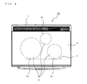
- Fig. 2 is a plan view of a body 1 of the induction cooking system according to Embodiment 1 of the invention.
- an induction cooking system 10 includes the body 1, and includes a top plate 2 and a control display unit (not shown) disposed on an uppermost portion of the body 1.
- Embodiment 1 A feature of Embodiment 1 is the large difference created between the outer diameters of the right and left induction heating coils 4.
- the outer diameter of an induction heating coil 4a on the left side is configured to be about 1.5 to about 2 times the size of an induction heating coil 4b on the right side. Since both employs a winding wire that has substantially the same width, the winding number increases in accordance with the largeness of the outer diameter of the induction heating coil.
- the induction heating coil 4a on the left side is used for cooking with the extra-large pot having a large bottom diameter.
- an induction heating coil having the second largest outer diameter which is, in this case, the induction heating coil 4b on the right side, is arranged for cooking with a pot having a moderate bottom diameter.
- an induction heating coil 4c having a further smaller outer diameter is arranged to heat a pot with a small bottom diameter.
- a forefront position of a print 3a corresponding to the induction heating coil on the left side viewed from the user and a forefront position of a print 3b corresponding to the right side of the induction heating coil are made to be in line as shown with the broken line. Since each size of the prints 3a and 3b on the top plate 2 corresponds to the outer diameter of the corresponding induction heating coils 4a and 4b, the forefront positions of the left and right induction heating coils 4a and 4b are also in line as shown with the broken line. With such a configuration as above, the occupied space of each induction heating coil 4 in the body 1 can be utilized effectively, and usability can be improved.
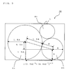
- Fig. 3 is an explanatory diagram illustrating the relation of the outer diameters of induction heating coils and a limit of the housing space in a housing chamber in the body 1 of the induction cooking system according to Embodiment 1 of the invention.
- the radius of the induction heating coil 4b on the right side is assumed to be A.
- the area occupied by the left and right induction heating coils 4a and 4b are as below.
- the range of the area occupied by the induction heating coils 4a and 4b in the left-right direction is expressed by the following equation (1).
- the length of the body 1 in the left-right direction needs to satisfy the following condition. 5.83A ⁇ (length of the body 1 in the left-right direction) Further, when the outer diameter of the induction heating coil 4a on the left side is 1.5 times the diameter of the induction heat coil 4b on the right side, the range of the area occupied by the induction heating coils 4a and 4b in the front-back direction is expressed as 3A. This 3A needs to be within the length of the body 1 in the front-back direction.
- the induction heating coil 4a for the extra-large pot is arranged on the left side and the induction heating coil 4b having an outer diameter that is substantially equivalent to those of conventional induction heating coils is arranged on the right side
- the positional arrangement may be opposite. That is, the induction heating coil 4a for the extra-large pot may be arranged on the right side and the induction heating coil 4b may be arranged on the left side.
- the forefront positions of the left and right induction heating coils 4a and 4b need to be in line as shown with the broken line.
- the position of the user is assumed to be substantially in the middle, the position of the side having the induction heating coil with an outer diameter that is substantially equivalent to those of conventional induction heating coils may be moved up.
- the top plate is configured to be rectangular
- the shape of the top plate and the body casing may be changed in the above example.
- the shape of each of the top plate and the body casing may be changed such that the induction heating coil 4a for the extra-large pot and the top plate 2 protrude out towards the front side.
- the forefront edge of the induction heating coil 4a and the forefront edge of the induction heating coil 4b are not in line in the front-back direction, when the user is cooking while placing two or more pots, such as the extra-large pot and an large pot, at the same time, the user only needs to move close to the heating port on the right side and slightly turn his/her body horizontally to cook with the two pots.
- This kind of cooking apparatus is preferably used when it is disposed in a corner of a kitchen having a corner.
Landscapes
- Physics & Mathematics (AREA)
- Electromagnetism (AREA)
- Induction Heating Cooking Devices (AREA)
Abstract
Description
- The present invention relates to an induction cooking system.
- There is a conventional induction cooking system that includes a flat top plate, and a pot placed on this top plate is heated by induction with the alternating magnetic field generated by the induction heating coil disposed under this top plate. Accordingly, a pan can be heated without the use of fire. Conventional induction cooking systems are known including at latest two induction heating coils in which two induction heating coils having the same outer diameter are typically arranged on the right and left front side viewed from the user (for example,
Patent Literatures 1 and 2). -
- Patent Literature 1: Japanese Unexamined Patent Application Publication No.
2002-198164 Figs. 1 to 4 ) - Patent Literature 2: Japanese Unexamined Patent Application Publication No.
2005-005132 Fig. 2 ) - However, since the conventional examples disclosed in
Patent Literature 1 andPatent Literature 2 are configured as above, when using a nonstandard extra-large pot (for example, an extra-large pot having a bottom diameter 1.5 to 2 times larger than the outer diameter of the induction heating coil), the portion of the pot bottom outside of the outer circumference of the induction heating coil is not only unheated but heat escapes from this portion. Consequently, this adversely affects the heating efficiency (cooking efficiency) disadvantageously.
Further, when cooking with an extra-large pot, which is so especially large that the pot covers a portion of both of the right and left adjoining heating coils, since the pot cannot be placed on the adjoining heating coil, cooking is disturbed which disadvantageously becomes the cause of drop in cooking efficiency. Additionally, in the induction heating coil having only a portion of the extra-large pot placed thereon, electromagnetic field leaks out from the portion of the extra-large pot not placed on the induction heating coil, thus disadvantageously consuming wasteful energy.
Furthermore, when, in order to overcome such a problem, the extra-large pot is shifted so as not to be placed on the adjoining induction heating coil, there are cases in which the extra-large pot comes into contact with a surrounding wall causing escape of heat through the wall. Because of this, the user has to continuously see to it that the extra-large pot does not come into contact with the surrounding wall, thus disadvantageously causes the cooking to become bothersome. - The invention has been made to overcome the above disadvantages and a main object thereof is to obtain an induction cooking system that is capable of cooking with an extra-large pot having a bottom diameter 1.5 to 2 times larger than a bottom diameter of a typically known large-size pot.
- The induction cooking system of the invention includes a body including a housing chamber housing a group of induction heating coils; and a top plate on which a heated object cooking with the induction heating coil is placed, the top plate being disposed on the upper portion of the body, in which the group of induction heating coils includes a first induction heating coil and a second induction heating coil, and an outer diameter of the first induction heating coil is 1.5 to 2 times an outer diameter of the second induction heating coil.
- According to the invention, since the group of induction heating coils includes an induction heating coil that has an outer diameter 1.5 to 2 times that of the other induction heating coils, cooking with an extra-large pot can be carried out.
-
- [
Fig. 1] Fig. 1 is a perspective view illustrating an appearance of an induction cooking system according toEmbodiment 1 of the invention in which a top plate is removed. - [
Fig. 2] Fig. 2 is a plan view of abody 1 of the induction cooking system according toEmbodiment 1 of the invention. - [
Fig. 3] Fig. 3 is an explanatory diagram illustrating the relation of outer diameters of induction heating coils and a limit of a housing space in a housing chamber in thebody 1 of the induction cooking system according toEmbodiment 1 of the invention. - [
Fig. 4] Fig. 4 is another exemplary arrangement of the induction cooking system according toEmbodiment 1 of the invention. - Now, a three-port induction cooking system with three heating ports is cited as an example, and description is given of a case in which the front left heating port of the induction heating coil is for an extra-large pot.
Fig. 1 is a perspective view illustrating an appearance of the induction cooking system according toEmbodiment 1 of the invention in which a top plate is removed, andFig. 2 is a plan view of abody 1 of the induction cooking system according toEmbodiment 1 of the invention. InFigs. 1 and2 , aninduction cooking system 10 includes thebody 1, and includes atop plate 2 and a control display unit (not shown) disposed on an uppermost portion of thebody 1.Prints 3 indicating the outer diameter of the three induction heating coils are done on thetop plate 2 and eachinduction heating coil 4 is disposed under thetop plate 2 in a position corresponding to theprint 3 of the induction heating coil. A feature ofEmbodiment 1 is the large difference created between the outer diameters of the right and leftinduction heating coils 4. For example, the outer diameter of aninduction heating coil 4a on the left side is configured to be about 1.5 to about 2 times the size of aninduction heating coil 4b on the right side. Since both employs a winding wire that has substantially the same width, the winding number increases in accordance with the largeness of the outer diameter of the induction heating coil. Theinduction heating coil 4a on the left side is used for cooking with the extra-large pot having a large bottom diameter. Further, in an area of thetop plate 2 other than the area occupied by theinduction heating coil 4a on the left side, an induction heating coil having the second largest outer diameter, which is, in this case, theinduction heating coil 4b on the right side, is arranged for cooking with a pot having a moderate bottom diameter. Furthermore, in an substantially center area of the area other than the area of thetop plate 2 occupied by the left and rightinduction heating coils induction heating coil 4c having a further smaller outer diameter is arranged to heat a pot with a small bottom diameter.
Additionally, in order to facilitate usability, a forefront position of a print 3a corresponding to the induction heating coil on the left side viewed from the user and a forefront position of a print 3b corresponding to the right side of the induction heating coil are made to be in line as shown with the broken line.
Since each size of the prints 3a and 3b on thetop plate 2 corresponds to the outer diameter of the correspondinginduction heating coils induction heating coils
With such a configuration as above, the occupied space of eachinduction heating coil 4 in thebody 1 can be utilized effectively, and usability can be improved. -
Fig. 3 is an explanatory diagram illustrating the relation of the outer diameters of induction heating coils and a limit of the housing space in a housing chamber in thebody 1 of the induction cooking system according toEmbodiment 1 of the invention.
Here, a case in which the outer diameter of theinduction heating coil 4a on the left side is 1.5 times the diameter of theinduction heat coil 4b on the right side will be described. The radius of theinduction heating coil 4b on the right side is assumed to be A. The area occupied by the left and rightinduction heating coils
The range of the area occupied by theinduction heating coils 
Here, the number after the ^ is a multiplier.
The value is about 4.95A.
This 4.95A needs to be within the length of thebody 1 in the left-right direction.
4.95A < (length of thebody 1 in the left-right direction)
When performing a calculation, in a similar manner, of a case in which the outer diameter of theinduction heating coil 4a on the left side is 2 times the diameter of theinduction heat coil 4b on the right side, then
5.83A < (length of thebody 1 in the left-right direction).
From the above, in order to satisfy a condition in which the outer diameter of one of the left and rightinduction heating coils 4 is 1.5 to 2 times the diameter of the otherinduction heating coil 4 while considering the gap needed between theinduction heating coils 4, the length of thebody 1 in the left-right direction needs to satisfy the following condition.
5.83A < (length of thebody 1 in the left-right direction)
Further, when the outer diameter of theinduction heating coil 4a on the left side is 1.5 times the diameter of theinduction heat coil 4b on the right side, the range of the area occupied by theinduction heating coils
This 3A needs to be within the length of thebody 1 in the front-back direction.
That is, 3A < (length of thebody 1 in the front-back direction)
When performing a calculation, in a similar manner, of a case in which the outer diameter of theinduction heating coil 4a on the left side is 2 times the diameter of theinduction heat coil 4b on the right side,
4A < (length of thebody 1 in the front-back direction)
From the above, the radius A of theinduction heating coil 4b on the right side needs to satisfy the following length.
(length of thebody 1 in the left-right direction) > 5.83A,
AND (length of thebody 1 in the front-back direction) > 4A. - Note that although in the above example, the
induction heating coil 4a for the extra-large pot is arranged on the left side and theinduction heating coil 4b having an outer diameter that is substantially equivalent to those of conventional induction heating coils is arranged on the right side, the positional arrangement may be opposite. That is, theinduction heating coil 4a for the extra-large pot may be arranged on the right side and theinduction heating coil 4b may be arranged on the left side. Also in this case, in order to facilitate the usability of the user, the forefront positions of the left and rightinduction heating coils - Further, although in the above example, the position of the user is assumed to be substantially in the middle, the position of the side having the induction heating coil with an outer diameter that is substantially equivalent to those of conventional induction heating coils may be moved up.
- Additionally, although the top plate is configured to be rectangular, the shape of the top plate and the body casing may be changed in the above example. For example, as shown in
Fig. 4 , the shape of each of the top plate and the body casing may be changed such that theinduction heating coil 4a for the extra-large pot and thetop plate 2 protrude out towards the front side. In this case, although the forefront edge of theinduction heating coil 4a and the forefront edge of theinduction heating coil 4b are not in line in the front-back direction, when the user is cooking while placing two or more pots, such as the extra-large pot and an large pot, at the same time, the user only needs to move close to the heating port on the right side and slightly turn his/her body horizontally to cook with the two pots. Further, in this case, since the user does not have to reach out his/her arm to the left/right, the load created when stretching ones arm to carry a heavy pot can be reduced substantially. Accordingly, the user can enjoy comfortable cooking. This kind of cooking apparatus is preferably used when it is disposed in a corner of a kitchen having a corner. - 1 body; 2 top plate; 3, 3a, 3b, 3c print of the induction heating coil; 4, 4a, 4b, 4c induction heating coil; 5 induction cooking system.
Claims (7)
- An induction cooking system, comprising:a body (1) including a housing chamber housing a group of induction heating coils (4); anda top plate (2) on which a heated object heated for cooking with each induction heating coil (4) is placed, the top plate (2) being disposed on the upper portion of the body (1), whereinthe group of induction heating coils (4) includes a first induction heating coil (4a) and a second induction heating coil (4b), andan outer diameter of the first induction heating coil (4a) is 1.5 to 2 times an outer diameter of the second induction heating coil (4b).
- An induction cooking system, comprising:a body (1) including a housing chamber housing a group of induction heating coils (4); anda top plate (2) on which a heated object heated for cooking with each induction heating coil (4) is placed, the top plate (2) being disposed on the upper portion of the body (1), whereinthe group of induction heating coils (4) includes a first induction heating coil (4a) that has an outer diameter substantially matching a bottom diameter of an extra-large pot, a second induction heating coil (4b) that has an outer diameter smaller than the outer diameter of the first induction heating coil (4a), and a third induction heating coil (4c) that has an outer diameter smaller than the outer diameter of the second induction heating coil (4b).
- The induction cooking system of claim 2, wherein the first induction heating coil (4a) is arranged in a front side of the top plate (2) in either a right or left side viewed from a user, the second induction heating coil (4b) is arranged in a front area of the top plate (2) other than the first area, and the third induction heating coil (4c) is arranged in an area of the top plate (2) other than the first area and the second area.
- The induction cooking system of claim 2 or 3, wherein an outer diameter of the first induction heating coil (4a) is 1.5 to 2 times an outer diameter of the second induction heating coil (4b).
- The induction cooking system of any one of claims 1 to 4, wherein a forefront edge of a print (3a) of the first induction heating coil (4a) and a forefront edge of a print (3b) of the second induction heating coil (4b) on the top plate (2) as viewed from a user are arranged to be the same distance from a foreside of the top plate (2) in the front-back direction.
- The induction cooking system of claim 5, wherein when assuming a radius of the second induction heating coil (4b) to be A, dimensions of the body (1) satisfies the following conditions:(length of the body 1 in the left-right direction) > 5.83A,AND (length of the body 1 in the front-back direction) > 4A.
- The induction cooking system of any one of claims 1 to 4, wherein shapes of the top plate (2) and a casing of the body (1) that houses the induction heating coil for the extra-large pot are changed so as to protrude out towards the user.
Applications Claiming Priority (2)
| Application Number | Priority Date | Filing Date | Title |
|---|---|---|---|
| JP2010047605 | 2010-03-04 | ||
| PCT/JP2011/000822 WO2011108200A1 (en) | 2010-03-04 | 2011-02-15 | Induction heating cookware |
Publications (2)
| Publication Number | Publication Date |
|---|---|
| EP2544507A1 true EP2544507A1 (en) | 2013-01-09 |
| EP2544507A4 EP2544507A4 (en) | 2014-11-19 |
Family
ID=44541871
Family Applications (1)
| Application Number | Title | Priority Date | Filing Date |
|---|---|---|---|
| EP11750314.4A Withdrawn EP2544507A4 (en) | 2010-03-04 | 2011-02-15 | INDUCTION HEATING KITCHEN BATTERY |
Country Status (4)
| Country | Link |
|---|---|
| EP (1) | EP2544507A4 (en) |
| JP (1) | JP5478709B2 (en) |
| CN (1) | CN102792770B (en) |
| WO (1) | WO2011108200A1 (en) |
Family Cites Families (14)
| Publication number | Priority date | Publication date | Assignee | Title |
|---|---|---|---|---|
| JP2002198164A (en) | 2000-12-27 | 2002-07-12 | Matsushita Electric Ind Co Ltd | Induction heating cooker |
| JP2003077629A (en) * | 2001-09-06 | 2003-03-14 | Matsushita Electric Ind Co Ltd | Induction heating cooker |
| JP2003265310A (en) * | 2002-03-15 | 2003-09-24 | Noritake Co Ltd | Electromagnetic heating vessel |
| ES2211303B1 (en) * | 2002-08-01 | 2005-10-01 | Bsh Electrodomesticos España, S.A. | INDUCTION KITCHEN PLATE WITH RECONFIGURABLE STRUCTURE WARMING AREAS AND PROCEDURE TO INCREASE THE MAXIMUM POWER OF SUCH WARMING ZONES. |
| JP3932428B2 (en) * | 2002-12-26 | 2007-06-20 | 三菱電機株式会社 | Cooker |
| JP2005005132A (en) | 2003-06-12 | 2005-01-06 | Hitachi Hometec Ltd | Induction heating cooker |
| JP2006252971A (en) * | 2005-03-11 | 2006-09-21 | Tokyo Electric Power Co Inc:The | Auxiliary jig for electromagnetic induction heating cooker |
| JP2007026789A (en) * | 2005-07-14 | 2007-02-01 | Nichiwa Denki Kk | Electromagnetic cooking device |
| ES2300168B1 (en) * | 2005-10-27 | 2009-05-08 | Bsh Electrodomesticos España, S.A. | KITCHEN HOB AND PROCEDURE FOR THE OPERATION OF A KITCHEN HOB. |
| CN102418947B (en) * | 2006-07-27 | 2014-06-18 | 松下电器产业株式会社 | Heating cooker |
| JP5040280B2 (en) * | 2006-12-04 | 2012-10-03 | パナソニック株式会社 | Induction heating cooker |
| JP4864850B2 (en) * | 2007-10-12 | 2012-02-01 | 三菱電機株式会社 | Induction heating cooker |
| JP2009123603A (en) * | 2007-11-16 | 2009-06-04 | Toshiba Corp | Induction heating cooker |
| JP4864118B2 (en) * | 2009-06-08 | 2012-02-01 | 三菱電機株式会社 | Induction heating cooker |
-
2011
- 2011-02-15 JP JP2012502984A patent/JP5478709B2/en not_active Expired - Fee Related
- 2011-02-15 EP EP11750314.4A patent/EP2544507A4/en not_active Withdrawn
- 2011-02-15 CN CN201180012218.3A patent/CN102792770B/en not_active Expired - Fee Related
- 2011-02-15 WO PCT/JP2011/000822 patent/WO2011108200A1/en not_active Ceased
Also Published As
| Publication number | Publication date |
|---|---|
| CN102792770A (en) | 2012-11-21 |
| WO2011108200A1 (en) | 2011-09-09 |
| HK1175060A1 (en) | 2013-06-21 |
| JPWO2011108200A1 (en) | 2013-06-20 |
| EP2544507A4 (en) | 2014-11-19 |
| JP5478709B2 (en) | 2014-04-23 |
| CN102792770B (en) | 2015-02-11 |
Similar Documents
| Publication | Publication Date | Title |
|---|---|---|
| EP2094060A2 (en) | Electric range and induction coil unit used therein | |
| US20200163171A1 (en) | Induction cooktop | |
| JP2007244558A (en) | Electric rice cooker | |
| EP2408261B1 (en) | A wok support for an induction hob | |
| EP3484241A1 (en) | Cooking hob | |
| KR20190001201A (en) | Pot detecting sensor and induction heating apparatus including thereof | |
| EP3291644B1 (en) | Induction heating cooking device | |
| EP3422814B1 (en) | Coil assembly and inductively-heating device including the coil assembly | |
| US10584883B2 (en) | Locator cover for a cooktop appliance | |
| JP5558387B2 (en) | Induction heating cooker | |
| CN216565645U (en) | Coil and magnetic stripe assembly structure and electric heating equipment | |
| CN102792770B (en) | Induction heating cookware | |
| KR20190001202A (en) | Induction heating apparatus | |
| JPWO2020240740A1 (en) | Cooling device and cooking system | |
| EP3297399B1 (en) | Induction heating cooking device | |
| CN208740625U (en) | Cooking apparatus | |
| CN215529359U (en) | Magnetic strip, magnetic strip assembly structure and electric heating device | |
| HK1175060B (en) | Induction heating cookware | |
| JP6080419B2 (en) | Induction heating cooker | |
| JP2018137247A (en) | Induction heating cooker | |
| JP4941097B2 (en) | Induction heating cooker | |
| WO2018042745A1 (en) | Induction-heating cooker | |
| JP5450191B2 (en) | IH cooker | |
| EP3698682A1 (en) | Wireless induction heating cooker with improved heat conduction efficiency and wireless induction heating system comprising the same | |
| KR102246237B1 (en) | Electric range |
Legal Events
| Date | Code | Title | Description |
|---|---|---|---|
| PUAI | Public reference made under article 153(3) epc to a published international application that has entered the european phase |
Free format text: ORIGINAL CODE: 0009012 |
|
| 17P | Request for examination filed |
Effective date: 20120827 |
|
| AK | Designated contracting states |
Kind code of ref document: A1 Designated state(s): AL AT BE BG CH CY CZ DE DK EE ES FI FR GB GR HR HU IE IS IT LI LT LU LV MC MK MT NL NO PL PT RO RS SE SI SK SM TR |
|
| DAX | Request for extension of the european patent (deleted) | ||
| A4 | Supplementary search report drawn up and despatched |
Effective date: 20141020 |
|
| RIC1 | Information provided on ipc code assigned before grant |
Ipc: H05B 6/12 20060101AFI20141014BHEP |
|
| GRAP | Despatch of communication of intention to grant a patent |
Free format text: ORIGINAL CODE: EPIDOSNIGR1 |
|
| INTG | Intention to grant announced |
Effective date: 20151014 |
|
| STAA | Information on the status of an ep patent application or granted ep patent |
Free format text: STATUS: THE APPLICATION IS DEEMED TO BE WITHDRAWN |
|
| 18D | Application deemed to be withdrawn |
Effective date: 20160225 |