EP2544500A1 - Concept pour la coordination d'interférence entre cellules dans un réseau de communication cellulaire - Google Patents
Concept pour la coordination d'interférence entre cellules dans un réseau de communication cellulaire Download PDFInfo
- Publication number
- EP2544500A1 EP2544500A1 EP11305863A EP11305863A EP2544500A1 EP 2544500 A1 EP2544500 A1 EP 2544500A1 EP 11305863 A EP11305863 A EP 11305863A EP 11305863 A EP11305863 A EP 11305863A EP 2544500 A1 EP2544500 A1 EP 2544500A1
- Authority
- EP
- European Patent Office
- Prior art keywords
- base station
- serving base
- interfering
- cell
- interfering base
- Prior art date
- Legal status (The legal status is an assumption and is not a legal conclusion. Google has not performed a legal analysis and makes no representation as to the accuracy of the status listed.)
- Granted
Links
Images


Classifications
-
- H—ELECTRICITY
- H04—ELECTRIC COMMUNICATION TECHNIQUE
- H04W—WIRELESS COMMUNICATION NETWORKS
- H04W72/00—Local resource management
- H04W72/50—Allocation or scheduling criteria for wireless resources
- H04W72/54—Allocation or scheduling criteria for wireless resources based on quality criteria
- H04W72/541—Allocation or scheduling criteria for wireless resources based on quality criteria using the level of interference
-
- H—ELECTRICITY
- H04—ELECTRIC COMMUNICATION TECHNIQUE
- H04W—WIRELESS COMMUNICATION NETWORKS
- H04W72/00—Local resource management
- H04W72/20—Control channels or signalling for resource management
- H04W72/27—Control channels or signalling for resource management between access points
-
- H—ELECTRICITY
- H04—ELECTRIC COMMUNICATION TECHNIQUE
- H04W—WIRELESS COMMUNICATION NETWORKS
- H04W72/00—Local resource management
- H04W72/50—Allocation or scheduling criteria for wireless resources
- H04W72/52—Allocation or scheduling criteria for wireless resources based on load
Definitions
- Embodiments of the present invention generally relate to wireless communications and, more specifically, to a concept for Inter-Cell Interference Coordination (ICIC) in a cellular communication network.
- IIC Inter-Cell Interference Coordination
- Wireless or cellular communication networks are steadily growing with an increasing number of systems for mobile communication being deployed. Due to the ever increasing demand for wireless communications, frequency spectrum for deploying new systems is increasingly scarce and, hence, an expensive resource.
- areas of adjacent cells or base station transceivers in a cellular communication system typically overlap, i.e. there is a geographically overlapping area at a border or edge between two adjacent cells or base station transceivers of a cellular communication system, wherein signals from either cells or base station transceivers may be received by a mobile terminal located close to that overlapping cell-edge area. While a mobile terminal may only be assigned to one cell, i.e. a serving cell or a serving base station, it may receive its desired signal from only its serving base station and experience other signals as interference. Interference between different or neighboring cells, which is commonly referred to as inter-cell interference, in cellular communication networks has always been an issue since mobile communication networks have been introduced.
- the impact of said inter-cell interference is more obvious for cell-edge users, i.e., for users or mobile terminals which are located in a border area of their serving cell.
- Such cell-edge users are more sensitive due to already relatively bad wireless channel conditions with their respective serving base stations. This may result in a poor reception at a cell edge or border in the downlink direction, i.e. the direction from the serving base station to an associated mobile terminal.
- Limited reception at the cell edge is an important issue for wireless network operators who want to provide full coverage inside their service area and at the same time guarantee a certain Quality of Service (QoS) to their subscribers independently of their location inside a cell.
- QoS Quality of Service
- Inter-Cell Interference Randomization aims at randomizing an interfering signal and thus allowing interference suppression at a mobile terminal either by applying (pseudo) random scrambling after channel coding/interleaving, such as commonly used in Code Division Multiple Access (CDMA) systems, such as e.g. the Universal Mobile Telecommunications System (UMTS), or using different kinds of frequency hopping, as e.g. also applied in the Global System for Mobile Communications (GSM).
- CDMA Code Division Multiple Access
- UMTS Universal Mobile Telecommunications System
- GSM Global System for Mobile Communications
- Inter-Cell Interference Cancellation is based on interference suppression which may e.g. be achieved by spatial suppression using multiple antennas at the mobile terminal. Instead, ICIC generally aims at applying restrictions to downlink resource management in a coordinated way between neighboring or adjacent cells. ICIC-techniques for multi-cell wireless systems such as e.g. GSM, Enhanced General Packet Radio Service (EGPRS), Enhanced Data Rates for GSM Evolution (EDGE), and UMTS have been investigated ever since these systems started to gain popularity.
- GSM Global System
- ESG Enhanced General Packet Radio Service
- EDGE Enhanced Data Rates for GSM Evolution
- UMTS UMTS
- LTE Long Term Evolution
- OFDM Orthogonal Frequency Division Multiplexing
- OFDMA Orthogonal Frequency Division Multiple Access
- inter-cell interference in OFDM-based systems arises when the same frequency resources are used in neighbor cells.
- a scenario is also commonly referred to as a frequency reuse of one.
- SINR Signal-to-Interference-plus-Noise Ratio
- ICIC mechanisms target to reduce the collision probabilities and to mitigate the SINR degradation that such radio resource collisions of neighboring cells may cause.
- neighboring cells may have some cell specific preferences for different subsets of radio resource blocks, or neighboring cells may employ reduced power for colliding radio resource blocks. Such restrictions in a cell will provide the possibility for improvement in SINR, and consequently to the cell-edge throughput and coverage.
- ICIC also requires communication between different network nodes in order to set and reconfigure these radio resource restrictions. Two cases are considered so far, the static one where reconfiguration of the resource restrictions is done on a time scale corresponding to days and the semi-static where the time scale is much smaller and corresponds to seconds.
- static ICIC methods are often applied to improve the interference situation for cell-edge mobile terminals. These static methods aim at reducing the individual transmission resources of a radio cell based on a coloring scheme of the radio cell controllers in the network independent of a current network load.
- Embodiments of the present invention may be based on the finding that a semi-static inter-cell interference coordination (ICIC) concept may adapt radio resource restrictions in response to a network load observed in the wireless radio access network.
- semi-static ICIC may provide gains by reducing interference in the vicinity of a radio cell.
- Embodiments provide an ICIC concept wherein each serving base station transceiver may identify its interfering neighbor base stations and may determine information about each. Then, a potential gain for a cell's serving base station may be estimated under the assumption that an identified interfering neighbor base station restrains from the use of a physical radio resource. Each serving base station may then transfer load information and the estimated potential gain to each of its interfering neighbor base station transceivers. Each interfering base station may evaluate the provided information under consideration of its own current load situation and may then optionally reduce the usage of certain physical radio resources to improve overall system performance.
- embodiments provide a method for inter-cell interference coordination in a cellular communication network comprising a plurality of radio cells, each radio cell being served by a serving base station.
- the method comprises the following steps:
- the method or the steps thereof may be executed either continuously, wherein in other embodiments the method may only be executed during an overload situation of the cellular communication network. That is to say the algorithm or method may be active all the time in some embodiments.
- the algorithm may, however, as well be deactivated if there is no physical radio resource shortage because of a comparatively low load in the cellular communication or radio access network.
- the relative physical radio resource usage of a base station may be compared against a predefined load-threshold in various embodiments.
- the method may be deactivated if the mobile terminals associated to the serving base station are mainly located close to the serving cell's center, i.e.
- CQI Channel Quality Indicator
- long term statistics of Channel Quality Indicator (CQI) reports may e.g. be compared against their short term statistics. This can be either a distribution or a percentile.
- the CQI is a measurement of a communication quality of wireless channels.
- CQI may be a value (or values) representing a measure of channel quality for a given channel.
- a high value CQI is indicative of a channel with high quality and vice versa.
- a CQI for a channel may be computed by making use of performance metric, such as a Signal-to-Noise Ratio (SNR) or a Signal-to-Interference plus Noise Ratio (SINR) of the channel. These values may be measured for a given channel and then used to compute a CQI for the channel.
- performance metric such as a Signal-to-Noise Ratio (SNR) or a Signal-to-Interference plus Noise Ratio (SINR) of the channel.
- a serving base station apparatus is adapted to perform a serving base station method for ICIC in a cellular communication network, wherein the serving base station method comprises determining a current load situation of the serving base station, identifying interfering base stations interfering a communication of the serving base station with its associated mobile terminals located in a border or edge area of the serving base station's served radio cell, estimating a hypothetical capacity gain for the serving base station under the premise that an identified interfering base station restrains a usage of at least a subset of its interfering physical radio resources, and transferring a report on the determined cell load and the estimated potential gain to each of the identified interfering base stations.
- step e) of the aforementioned method may be executed by an apparatus for an interfering base station.
- an interfering base station apparatus according to embodiments of the present invention is adapted to perform an interfering base station method for ICIC in a cellular communication network, wherein the interfering base station method comprises evaluating, based on a current load situation of the interfering base station, at least one report transferred to the interfering base station from at least one neighboring serving base station, the at least one report being indicative of a cell load and an estimated hypothetical capacity gain for the serving base station under the premise that the interfering base station restrains a usage of at least a subset of its interfering physical radio resources, in order to optionally reduce the usage of the interfering base station's physical radio resources based on the evaluation.
- determining the serving base station's current load situation may comprise determining physical radio resource blocks used for dedicated communication of useful data from the serving base station to its associated mobile terminals and/or vice versa.
- physical radio resource blocks may be understood as frequency portions, such as e.g. subcarriers of an OFDMA based system, time portions, such as e.g. time slots or frames, or a combination thereof.
- frequency portions such as e.g. subcarriers of an OFDMA based system
- time portions such as e.g. time slots or frames, or a combination thereof.
- PRBs physical resource blocks
- PRBs physical resource blocks
- Allocation of PRBs may be handled by a scheduling function at a base station (eNodeB).
- a PRB is defined as consisting of twelve consecutive subcarriers for one slot (0.5 msec) in duration.
- a PRB may be the smallest element of resource allocation assigned by a base station scheduler.
- a load generated by users in a cell may be understood as the physical radio resources used to serve these users in relation to totally available physical radio resources. For example, the number of frequency carriers or time slots used to serve the users in relation to the total number of frequency carriers or time slots available.
- measurement reports of mobile terminals may be evaluated by the serving base station to identify potentially interfering neighbor cells served by neighbor base stations.
- HandOver (HO) measurements which may be carried out by a mobile terminal on a regular basis, may be used. In this case the mobile terminals are sending their measurements to the serving base station just before HO.
- the serving base station will evaluate this information and, based thereon, will generate reports to the interfering base stations.
- Handover is a key functionality of most cellular communication systems which tries to keep a mobile terminal connected possibly to the best base station in its vicinity. Handover is usually based on downlink received signal strength (RSS) and Carrier-to-Interference Ratio (CIR) measurements of the mobile terminal. Processing of a HO measurements is usually done in Layer 1 (L1) and Layer 3 (L3) by the mobile terminal. The HO is then initiated by the serving base station if certain event criteria are met.
- L1 Layer 1
- L3 Layer 3
- a mobile terminal performs downlink radio channel measurements based on reference or pilot symbols. In particular, the mobile terminal can measure the Reference Symbols Received Power (RSRP) and the Reference Symbols Received Quality (RSRQ).
- RSRP Reference Symbols Received Power
- RSRQ Reference Symbols Received Quality
- the mobile terminal sends the corresponding measurement report indicating the triggered event.
- the RSRP and RSRQ may be measured based on the reference symbols received from the serving cell and from the strongest adjacent (interfering) cells.
- handover may be triggered when an RSRP value from an adjacent cell is higher than the one from the serving cell by a number of dBs equal to HO hysteresis; this condition has to be satisfied for a time period which commonly referred to as Time-To-Trigger (TTT).
- TTT Time-To-Trigger
- HO measurements or HO measurements reports provide a slightly delayed view of the inter-cell interference situation, since they are only triggered when a neighbor cell becomes a predefined amount of offset better than the serving cell (A3 event).
- additional or alternative mobile terminal measurements may be configured such that they are dedicated to the measurement of a more current inter-cell interference situation, thereby providing a more current view of the inter-cell interference situation.
- a so-called A2 event i.e. when serving becomes worse than a predefined threshold, may be instantaneously reported from an associated mobile terminal to its serving base station.
- Such additional or alternative measurement reports may be configured to identify mobile terminals at the cell border. In this case the mobile terminals are sending their measurements to the serving base station if they enter the cell border. For example, if a 3dB cell border window is assumed, then there will be a higher number of reports, because mobiles may enter and leave the cell border without handing over to another cell. Hence, such additional measurement reports would cause additional traffic in the air interface.
- identifying the interfering base stations may comprise measurements of an associated mobile terminal located in the border area of the radio cell, the measurements being directed towards signal strength (RSRP) and/or signal quality (RSRQ) of base stations being in vicinity of the associated mobile terminal.
- RSRP signal strength
- RSRQ signal quality
- identifying the interfering base stations may also comprise specifically instructing an associated mobile terminal located in the border or edge area of the radio cell to perform measurements related to base stations being in vicinity of the associated mobile terminal, i.e. its serving base station and potentially interfering base stations. Whether a mobile terminal is located in the border area may e.g. be determined based on CQI values reported from the mobile terminals in uplink direction.
- estimating the hypothetical capacity gain hence comprises determining the cumulated hypothetical capacity gain G s,i related to a plurality of mobile terminals located in the border area of the radio cell and being associated to the serving base station s under the assumption that an interfering base station i is not transmitting on certain physical downlink radio resources.
- ⁇ C (.) denotes an estimation of a corresponding channel capacity through a mapping function ⁇ C (.).
- ACM adaptive coding and modulation
- I m , i represents the RSRP of the interfering base station i
- S m,s corresponds to the average power of all physical resource elements which carry cell-specific reference signals over an entire communications bandwidth (RSRP)
- the estimate T may be improved by taking a mobile terminal's S and Q measurements of more than one cell into account. For example, the mobile terminal may measure S and Q of a plurality of neighboring cells and report them to its serving cell as well. There, an improved estimate for T m may then be computed.
- step d) i.e. transferring the report, the cumulated capacity gain G s , i of the serving base station s , under the assumption that interfering base station i is not transmitting, may be transferred from said serving base station s to said interfering base station i, e.g. using the X2 inter-base station interface or the air interface.
- information on a current load situation of the serving base station s may be provided to the interfering base station i via the X2 interface or the air interface.
- Each interfering base station i will receive reports from a plurality of adjacent serving base stations. Based on the received reports, each interfering base station i may calculate a hypothetical combined capacity gain of all neighboring serving base stations s under the assumption that the interfering base station i is not transmitting any data to its mobiles using specific physical radio resources. Based on this information (load, hypothetical gain), and with the help of a target function, the interfering base station i may decide on the amount of physical radio resources employed to serve mobiles attached to it.
- the interfering base station i may decide, based on the at least one received report on a serving base station's determined cell load and its estimated hypothetical gain G s,i on an amount of physical radio resources which the interfering base station may use for communicating with its associated mobile terminals. Load information per serving base station is available at the interfering base station i for guaranteed and best effort traffic separately.
- the highest priority of the interfering base station i may be to serve its own associated mobile terminals with at least a predefined guaranteed rate.
- a second highest priority may be to enable another (serving) base station to serve its associated mobile terminals at a respective guaranteed rate.
- the interfering base station may decide on the amount of physical radio resources given that communicating with its associated mobile terminals with at least a guaranteed data rate has a highest priority, and given that a communication of a serving base station with its associated mobile terminals with at least a guaranteed data rate has the second highest priority.
- the interfering base station i may also decide to drop one of its associated users in order to best serve the overall network performance. In this case the communication of a neighboring serving base station with its associated mobile terminals with at least a guaranteed data rate has the highest priority.
- this ICIC concept may also be extended to identify mobile terminals for coordinated scheduling and multipoint transmission in downlink.
- Some embodiments comprise digital control circuits installed within the serving base station's and/or interfering base station's apparatus' electrical circuitry. Such a digital control circuit, e.g. a digital signal processor (DSP), needs to be programmed accordingly.
- a digital control circuit e.g. a digital signal processor (DSP)
- DSP digital signal processor
- yet further embodiments also provide a computer program having a program code for performing at least a step of embodiments of the aforementioned methods, when the computer program is executed on a computer or a digital processor.
- Embodiments of the present invention may allow mobile network operators (MNOs) to further optimize a performance of a wireless communication network with respect to inter-cell interference and, hence, throughput. Further, embodiments of the present invention may support load balancing in highly loaded radio access networks, as will be described in more detail below. Load Balancing may support a cellular radio network to adapt to varying traffic load densities and thereby may increase the network throughput. When the load of a particular cell is too high, then load balancing can transfer traffic towards another lower loaded cell and/or support that highly loaded cell, e.g. via reducing its received inter-cell interference.
- the system may adapt in a flexible way to the current cell load situations, with the result that the users experience a higher quality of service, and that the total system throughput ⁇ at a constant quality level ⁇ can be increased. This may lead to a more relaxed cellular network planning and/or to a delayed need to install additional cells in growing networks which directly results in reduced capital expenditures for the network operator.
- Fig. 1 schematically shows a flow chart of a method 10 for inter-cell interference coordination in a cellular communication network, according to an embodiment.
- the method comprises a step 11 of determining a current load situation of a serving base station s , a step 12 of identifying interfering base stations i interfering a communication of the serving base station s with its associated mobile terminals located in a border or edge area of the serving base station's served radio cell.
- the step 12 of identifying is followed by a step 13 of estimating a hypothetical capacity gain G s,i for the serving base station s under the premise that an identified interfering base station i does not use its interfering physical radio resources.
- a report on the serving base station's current load situation and the estimated hypothetical capacity gain is transferred from the serving base station s to each of the identified interfering base stations i.
- At an identified interfering base station i at least one report transferred from at least one neighboring serving base station is evaluated in a step 15, in order to possibly reduce (step 16) a usage of said identified interfering base station's physical radio resources based on the evaluation and an own current load situation of the identified interfering base station.
- the method 10 or individual steps thereof may be executed continuously and independently from a current network load.
- the method 10 or individual steps thereof may only be executed during an overload situation of the cellular communication network.
- a relative physical radio resource usage of the serving base station may be compared against a predefined load-threshold in such embodiments.
- the method 10 or individual steps thereof may be deactivated if mobile terminals associated to the serving base station are mainly located close to said serving base station. For a related decision on whether a mobile terminal is located in the serving cell's edge area or close to its center, CQI values reported from a mobile terminal to its serving base station in uplink direction may be taken into account, for example.
- the steps 11 to 14 of the ICIC method 10 may be executed by a serving base station or an apparatus thereof, while the steps 15 and 16 may be executed by an interfering base station or an apparatus thereof.
- a first serving base station may be an interfering base station for a second (neighboring or adjacent) serving base station, and vice versa.
- Fig. 2 schematically shows a block diagram of a serving base station apparatus 20, according to an embodiment.
- a serving base station apparatus may be understood as a serving base station itself or an apparatus for usage in or in conjunction with a serving base station.
- the serving base station apparatus 20 comprises means 21 for determining a current load situation of the serving base station s . Further, the serving base station apparatus 20 comprises means 22 for identifying neighboring interfering base stations i, interfering a communication of the serving base station s with its associated mobile terminals located in an edge area of the serving base station's served radio cell. The means 22 for identifying neighboring interfering base stations may be coupled to means 23 for estimating the hypothetical capacity gain G s,i for the serving base station s given that an identified interfering base station i restrains the usage of at least a subset of its interfering physical radio resources.
- the means 23 for estimating and the means 21 for determining are coupled to a means 24 for transferring a report on the determined serving base station's current load situation and the estimated hypothetical capacity gain G s,i to each of the identified interfering base stations stations i.
- the means 21, 22, and 23 may comprise individual or common electrical signal processing circuitry
- the means 24 for transferring may comprise or may be comprised by an analog and/or digital radio transceiver, for example.
- the serving base station apparatus 20 is adapted or configured to perform a serving base station method for ICIC in a cellular communication network, wherein the serving base station method comprises the steps 11 to 14 of method 10.
- the means 21 for determining the serving base station's current load situation may be adapted to determine physical radio resource blocks being actually used for dedicated communication of the serving base station with its associated mobile terminals. A number of these used or occupied physical radio resource blocks may then then be compared against a total number of physical radio resource blocks available for dedicated communication with associated mobile terminals in order to determine a value indicative of a current load situation of the serving base station. For example, a load of 100% is achieved when a serving base station transmits using all its available resources in time and frequency for communicating useful data to its associated mobile terminals. In contrast thereto, a serving base station experiences a load of 0% when no dedicated data is transmitted to any mobile terminal.
- measurements sent to the serving base station in the uplink from associated cell-edge mobile terminals may be evaluated in order to identify interfering neighbor cells served by neighboring serving base stations, i.e. potentially interfering base stations. If certain network configured conditions are fulfilled, as e.g. A2 or A3 events, the mobile terminal may send the corresponding measurement report indicating the triggered event.
- measurements may be used, in which a mobile terminal measures the RSRP and the RSRQ of its serving cell and a plurality of visible neighbor cells, respectively. For HO measurements, a respective report may be sent to the serving cell in case the measured neighbor cell becomes a certain amount of offset better than the serving cell (e. g. A3 event).
- a measurement report may be transferred to the serving base station as soon as the serving becomes worse than a predefined threshold (e.g. A2 event).
- a predefined threshold e.g. A2 event
- the latter measurement reports may cause additional traffic in the air interface.
- a mobile terminal's measurement report may comprise the following information:
- the means 22 for identifying neighboring interfering base stations is adapted, respectively, to receive and process measurements of an associated mobile terminal located in the cell-edge area, the measurements being directed towards signal strength and/or signal quality of base stations being in vicinity of the associated mobile terminal.
- the means 22 for identifying neighboring interfering base stations may also be adapted to actively instruct an associated mobile terminal located in the border or edge area of the radio cell to perform measurements related to base stations being in vicinity of the associated mobile terminal, i.e. its serving base station and interfering base stations. Whether a mobile terminal is located in the cell-edge area may e.g. be determined based on CQI values reported from the mobile terminals in uplink direction.
- a serving base station apparatus 20 for serving base station s may generate a report, respectively, the report holding cumulated hypothetical capacity gains for all mobiles associated to the serving base station s under the condition that the interfering base station i being currently considered is not transmitting, i.e. not interfering.
- This report may then be conveyed from the serving base station s to the interfering base station i via an inter-base station interface.
- the X2 inter-base station interface or the air interface may be used for that purpose.
- the means 23 for estimating the hypothetical capacity gain hence may be adapted to determine the cumulated hypothetical capacity gain G s,i related to a plurality of mobile terminals located in the border area of the served radio cell and being associated to the serving base station s under the assumption that the interfering base station i is not transmitting on certain physical downlink resource blocks.
- the cumulated capacity gain G s , i may be determined based on the aforementioned equations (1) to (4), wherein, in some embodiments, the estimate T m for the total received power may be improved by taking a mobile terminal's RSRP and RSRQ measurements of more than one cell into account.
- the mobile terminal may measure RSRP and RSRQ of its serving cell and of a plurality of neighboring cells and report those to its serving cell, respectively.
- the means 23 for estimating may be adapted to compute an improved estimate for the total received power T m based on the RSRP and RSRQ measurements of the more than one radio cell.
- the means 24 for transferring may be adapted to transfer information indicative of the estimated hypothetical capacity gain G s,i from said serving base station s to said interfering base station i, e.g. using the X2 inter-base station interface.
- information on the estimated or determined current load situation of the serving base station s may be provided to the interfering base station i via the X2 interface.
- FIG. 3 it is show a schematic block diagram of an interfering base station apparatus 30, according to an embodiment.
- the interfering base station apparatus 30 comprises means 31 for evaluating, based on a current load situation of the interfering base station i, at least one neighboring serving base station's report transferred to the interfering base station i from at least one neighboring serving base station s , the at least one report comprising information indicative of the serving base station's load and an estimated hypothetical capacity gain G s,i for the serving base station s under the assumption that the interfering base station i limits the usage of at least a subset of its interfering physical radio resources.
- the means 31 for evaluating may interact with means 32 in order to optionally reduce the usage of the interfering base station's interfering physical resources based on an outcome of the evaluation by means 31.
- the means 31 for evaluating also may comprise analog and/digital signal processor circuitry, while the means 32 for reducing the usage of the interfering base station's physical resources may comprise or may be comprised by an analog and/or digital radio transceiver circuitry, for example.
- the interfering base station apparatus 30 is adapted to perform an interfering base station method for ICIC in a cellular communication network, wherein the interfering base station method comprises the steps 15 and 16 of method 10.
- the decision on the employed physical radio resources may involve a decision on an amount and/or an interference preventing allocation of the physical radio resources.
- the means 31 for evaluating may be adapted to determine the hypothetical combined cumulated capacity gain G i based on equation (5).
- the interfering base station apparatus 30 may decide, based on the at least one received report on a serving base station's determined cell load and its estimated hypothetical gain G s,i , on an amount of physical radio resources which the interfering base station i may use for communicating with its associated mobile terminals. For that purpose load information per serving base station is available at the interfering base station apparatus 30 for guaranteed and best effort traffic separately.
- the interfering base station apparatus 30 may be adapted to serve its own associated mobile terminals with at least a predefined guaranteed rate at highest priority. Further, the interfering base station apparatus 30 may be adapted to enable another (serving) base station to serve its associated mobile terminals at a respective guaranteed rate at second highest priority.
- the interfering base station may decide on the amount of physical radio resources given that communicating with its associated mobile terminals with at least a guaranteed data rate has a highest priority, and given that a communication of a serving base station with its associated mobile terminals with at least a guaranteed data rate has the second highest priority.
- the interfering base station apparatus 30 may also be adapted to drop one of its associated mobile terminals in order to best serve the overall network performance. In this case the communication of a neighboring serving base station with its associated mobile terminals with at least a guaranteed data rate has the highest priority.
- the base station apparatuses 20 and 30 may comprise a signal processor, respectively, executing a computer program having a program code for performing or supporting at least one of the above described method-steps, when the computer program is executed on said processor.
- embodiments may provide a computer program having a program code for performing one of the above described methods when the computer program is executed on a computer or processor.
- program storage devices e.g., digital data storage media, which are machine or computer readable and encode machine-executable or computer-executable programs of instructions, wherein said instructions perform some or all of the steps of said above-described methods.
- the program storage devices may be, e.g., digital memories, magnetic storage media such as a magnetic disks and magnetic tapes, hard drives, or optically readable digital data storage media.
- the embodiments are also intended to cover computers programmed to perform said steps of the above-described methods.
- a serving base station transceiver suggests to a neighboring interfering base station transceiver to restrict usage of resources.
- the interfering base station transceiver may either reject the request if it is short of own resources or compares the gain in the origination base station transceiver and agrees on the restriction, if said gain compensates the loss of the interfering base station transceiver's throughput.
- Embodiments of the present invention may be used for interference mitigation as well as for Load Balancing (LB).
- Load balancing supports a cellular radio network to adapt to varying traffic load densities and thereby may increase network throughput.
- load balancing can transfer traffic towards another lower loaded cell and/or support that highly loaded cell e.g. via reducing its received inter-cell interference.
- the system may adapt in a flexible way to the current cell load situations, with the result that the users experience a higher quality of service, and that the total system throughput ⁇ at a constant quality level ⁇ can be increased. This leads to a more relaxed cellular network planning and/or to a delayed need to install additional cells in growing networks which directly results in reduced CapEx costs for the network operator.
- the expression “Load” or “Cell Load” describes how “full” a cell is being judged for a particular purpose.
- Typical measures for cell load are based on the resource usage, such as the Physical Resource Block (PRB) usage in LTE, the user received service quality, such as by which average data rate a particular service can be provided and/or the dropping/blocking probability.
- Hardware constraints and link capabilities are another dimension which could be considered for the cell load determination.
- Such physical cell values are then convoluted in order to extract a characterizing load metric which serves as input for LB algorithms. The choice of this load metric as a part of the load balancing algorithm depends on the load balancing strategy.
- Load balancing may be restricted on only handover (HO) techniques.
- HO handover
- embodiments of the present ICIC concept additionally may provide a significant benefit.
- the potential of these two load balancing techniques is evaluated and compared in order to obtain their maximum performance gain values.
- LTE deployments use a frequency reuse 1 and in most scenarios the interference limits the cell capacity.
- one cell can be supported when its neighboring cells would cause less interference. Consequently, better SINR values are available within this supported cell. Due to this improved signal quality, this cell is now able to transport a larger amount of traffic with the same given amount of resources. The price for this is that neighboring cell(s) restrict or omit the usage of some of their own frequency recourses and thereby do potentially lower their own capacity.
- ICIC In the subsequent investigation with a highly loaded center cell, an ICIC scheme was chosen for which the maximum ICIC gain is expected. This ICIC scheme is schematically illustrated in Fig. 4a , whereby all cells or sectors without restrictions are indicated by white color. For the other cells or sectors 41 to 46 only specific non-overlapping physical radio resources are chosen, respectively. A frequency selective scheduler is used to take advantage of ICIC.
- Intra-system intra-frequency handover has been investigated as second load balancing mechanism.
- mobiles located at the cell edge are re-assigned to a lower loaded neighbor cell. This is done only if the mobile can be served by the neighbor cell with a sufficient SINR and as long as the neighbor cell has enough resources available.
- a round robin scheduler was used in all simulations which do not apply ICIC.
- the exchange of load information is already standardized in 3GPP and comprises the PRB usage for Guaranteed Bit Rate (GBR), non-GBR and total GBR usage for the uplink and downlink direction, respectively. Additionally, hardware load and transport network layer load indicators are specified. These load indicators are required as input parameters for self-x algorithm (e.g. self-planning, self-configuration, self-optimization, self-healing, self-maintenance, etc.) for both load balancing mechanisms.
- GBR Guaranteed Bit Rate
- non-GBR non-GBR
- total GBR usage for the uplink and downlink direction
- hardware load and transport network layer load indicators are specified. These load indicators are required as input parameters for self-x algorithm (e.g. self-planning, self-configuration, self-optimization, self-healing, self-maintenance, etc.) for both load balancing mechanisms.
- load balancing algorithm In case a load balancing algorithm is used, it will typically be implemented per base station transceiver. It processes information available there and will negotiate control information via the X2 interface with peer entities in neighboring base station transceivers. Relevant neighbors are identified via the neighbor relation table. The input data can be separated to data available at the individual transceiver like e.g. PRB usage, handover measurements and to common knowledge shared between base station transceivers as e.g. load or color information.
- the input data is typically limited to load information from neighbors and to data available in the hosting base station transceiver.
- this algorithm negotiates the mobility parameter settings with its peers.
- Embodiments of the ICIC concept try to restrain the usage of PRB which cause a high interference to mobiles associated to neighbor cells. Yet this information is not a priori available at the base station transceiver. Therefore often simpler approaches based on static or semi-static cell coloring are used to identify the PRB dedicated to load balancing.
- a signaling between base stations may be required for exchanging coloring information and for initiating a re-coloring to adapt the ICIC scheme to the actual load situation.
- the 3GPP standardized signaling for the negotiation of mobility parameter settings is mandatory in 3GPP. Because it is foreseen for both, handover optimization and load balancing and because the information required for load balancing by ICIC is not directly accessible, the implementation of load balancing by ICIC is considered to be more complex.
- Simulations were carried out on a playground 47 with 21 tri-sectored cells as illustrated in Fig. 4b .
- the offered traffic can be configured separately for the center cell 48 and for the other cells.
- the offered traffic can be placed in such a way that that a certain percentage of the users are located within the cell edge area.
- the investigated cell edge traffic percentages are 15% (nearly uniform traffic distribution within the cell), 30% and 50%.
- the system performance was measured in terms of the total throughput within an evaluation area consisting of the center cell 48 and its six directly neighboring cells.
- the center cell load and the other cell load was varied (center cell [Mbps]: 3, 5, 7, 9, 11, 13, 15, 17, 19, 21, 23, 25.
- the maximum supported traffic in the respective scenario was used. This was measured by comparing the load offered in the evaluation area against the load carried in that area. When the offered traffic is increased in the center cell, at a certain point the cell saturates and cannot carry more traffic. The performance figure is defined as that point where the carried load drops below 97% of the offered load.
- the load balancing gain is then calculated as the ratio between the investigated scenario and the reference scenario "none".
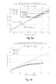
- Figs. 5a to 5c depict the system performance for different load balancing scenarios at different load levels. These graphs show on the Y-axis the total carried traffic within the evaluation area.
- This evaluation area consists of the center cell 48 and its ring of six directly neighboring cells. While the input traffic load of the other cells is kept at constant levels of 5 MBit/s in Fig. 5a , 11 MB/s in Fig. 5b and 20 MB/s in Fig. 5c , the offered traffic load of the single center cell 48 is varied as shown on the top X-axis of the graphs. The bottom X-axis denotes the total offered traffic load within this evaluation area.
- Fig. 5a shows how the carried traffic saturates as the offered traffic increases.
- all load balancing techniques lead to a performance gain by shifting the point where the carried traffic drops down to 97% of the offered traffic.
- the capabilities of load balancing via handover parameter variation performance are larger than the one of ICIC.
- Handover parameter variation is a very powerful load balancing technique in this medium load range. Neighboring cells are not fully loaded, so the highly loaded center cell is able to transfer some of its mobiles to neighboring cells which still have free capacity to take over some additional users. The neighboring cells suffer by having to spend a lot of resources to serve distant mobiles, but as these neighboring cells have sufficient unused resources, this additional resource consumption does not harm the throughput and Quality of Service (QoS) performance of those cells; the total system throughput can considerably be increased.
- QoS Quality of Service
- ICIC has a large capability to optimize the interference situation.
- embodiments of the ICIC concept may provide an appreciable maximal reachable performance gain of up to 16% as is visualized in Fig. 6a .
- the maximal reachable ICIC potential is reached at such high load levels.
- the traffic load gets even higher or overloaded, then the ICIC potential for load balancing is decreasing. This is because no free resources are available anywhere which could be coordinated for the purpose of interference mitigation or which may be arranged intelligently for load balancing.
- link adaptation modeling characteristic leads to a further small performance degradation. This, however, is a simulation artifact due to underestimated link capacities.
- Fig. 5c shows the situation for a scenario where the other cells are overloaded and load balancing techniques can no longer be beneficial for the system performance.
- Load balancing by handover fails because target cells are out of resources and cannot take over more traffic.
- ICIC fails because every cell does fully use all its resources.
- Fig. 6a to 6c show the extracted relative performance gains for different percentages of mobiles located at the cell edge in relation to the total number of mobiles within the cell.
- Handover parameter variation can lead to an extremely high performance gain of up to more than 27%.
- the reachable gain via handovers is the larger the more users are close to the cell border and the lower the traffic load is in neighboring cells.
- there is a handover benefit as long as neighboring cells do still have enough free resources to take over additional users without having to decrease the guaranteed service of their own already present users.
- no free resources are left, then there is no longer a load balancing benefit with this handover algorithm.
- Other handover algorithms may show different high load behavior, i.e. those type of handover algorithms where a full target cell is still allowed to accept additional users for the price of a reduced service quality for the target cell users.
- Inter-cell interference coordination shows contrary and complementing gain behavior.
- the reachable performance gains increase up to reasonably high traffic load level.
- maximum ICIC gains of 16%, 13% and 11% were obtained. It needs to be noted, that those gains are the upper bound for an ideal ICIC scenario.
- the ICIC gain gets smaller again until there is no ICIC gain anymore in situations where all cells are overloaded.
- there is a low or medium traffic load then there is not too much interference anyway, and thus ICIC does not have too much potential to lead a benefit.
- the ICIC load balancing benefit is focused on a certain load range around reasonably high traffic load, where it has the potential to reach appreciable benefits in particular scenarios.
- Both techniques, ICIC and handovers, are complementary, and can beneficially be combined at certain load levels.
- a usage of both techniques simultaneously leads to a considerable advantage from low up to medium-high other load levels, here up to about 8 Mbps other cell loads, above which the handover penalty would outweigh the handover benefits.
- ICIC alone does then show the highest potential.
- the scenario for this study has especially been designed to obtain the maximum reachable benefit, i.e. the center cell is maximally supported by its neighboring cells.
- the performance values could be considered as upper bound of the maximum reachable load balancing benefit.
- the selected scenario reflects the overload situation in limited geographic areas for which load balancing is designed.
- the load balancing mechanisms investigated here act in principle on cell-edge users and therefore require a higher cell edge user density.
- the simulation results reflect this in terms of a pronounced impact of the user density at the cell edge on load balancing gain.
- the impact has turned out to be less than expected. This means that load balancing is beneficial not only in very extreme and rare load distributions with high user densities at cell edge.
- embodiments may allow mobile network operators to further optimize a performance of their existing and future wireless communication networks with respect to inter-cell interference, load balancing in highly loaded radio access networks, and, hence, throughput.
- the communication system may adapt in a flexible way to the current cell load situations, with the result that the users may experience a higher quality of service, and that the total system throughput ⁇ at a constant quality level ⁇ can be increased. This may lead to a more relaxed cellular network planning and/or to a delayed need to install additional cells in growing networks which directly results in reduced capital expenditures for the network operator.
- Functional blocks denoted as "means for " shall be understood as functional blocks comprising circuitry that is adapted for performing a certain function, respectively.
- a "means for s.th.” may as well be understood as a “means being adapted or suited for s.th.”.
- a means being adapted for performing a certain function does, hence, not imply that such means necessarily is performing said function (at a given time instant).
- processor any functional blocks may be provided through the use of dedicated hardware, as e.g. a processor, as well as hardware capable of executing software in association with appropriate software.
- the functions may be provided by a single dedicated processor, by a single shared processor, or by a plurality of individual processors, some of which may be shared.
- explicit use of the term "processor” or “controller” should not be construed to refer exclusively to hardware capable of executing software, and may implicitly include, without limitation, digital signal processor (DSP) hardware, network processor, application specific integrated circuit (ASIC), field programmable gate array (FPGA), read only memory (ROM) for storing software, random access memory (RAM), and nonvolatile storage.
- DSP digital signal processor
- ASIC application specific integrated circuit
- FPGA field programmable gate array
- ROM read only memory
- RAM random access memory
- nonvolatile storage Other hardware, conventional and/or custom, may also be included.
- any block diagrams herein represent conceptual views of illustrative circuitry embodying the principles of the invention.
- any flow charts, flow diagrams, state transition diagrams, pseudo code, and the like represent various processes which may be substantially represented in computer readable medium and so executed by a computer or processor, whether or not such computer or processor is explicitly shown.
Landscapes
- Engineering & Computer Science (AREA)
- Quality & Reliability (AREA)
- Computer Networks & Wireless Communication (AREA)
- Signal Processing (AREA)
- Mobile Radio Communication Systems (AREA)
Priority Applications (2)
| Application Number | Priority Date | Filing Date | Title |
|---|---|---|---|
| ES11305863.0T ES2649891T3 (es) | 2011-07-05 | 2011-07-05 | Concepto para coordinación de interferencia entre células en una red de comunicación celular |
| EP11305863.0A EP2544500B1 (fr) | 2011-07-05 | 2011-07-05 | Concept pour la coordination d'interférence entre cellules dans un réseau de communication cellulaire |
Applications Claiming Priority (1)
| Application Number | Priority Date | Filing Date | Title |
|---|---|---|---|
| EP11305863.0A EP2544500B1 (fr) | 2011-07-05 | 2011-07-05 | Concept pour la coordination d'interférence entre cellules dans un réseau de communication cellulaire |
Publications (2)
| Publication Number | Publication Date |
|---|---|
| EP2544500A1 true EP2544500A1 (fr) | 2013-01-09 |
| EP2544500B1 EP2544500B1 (fr) | 2017-08-30 |
Family
ID=44534195
Family Applications (1)
| Application Number | Title | Priority Date | Filing Date |
|---|---|---|---|
| EP11305863.0A Not-in-force EP2544500B1 (fr) | 2011-07-05 | 2011-07-05 | Concept pour la coordination d'interférence entre cellules dans un réseau de communication cellulaire |
Country Status (2)
| Country | Link |
|---|---|
| EP (1) | EP2544500B1 (fr) |
| ES (1) | ES2649891T3 (fr) |
Cited By (4)
| Publication number | Priority date | Publication date | Assignee | Title |
|---|---|---|---|---|
| WO2017088903A1 (fr) * | 2015-11-24 | 2017-06-01 | Telefonaktiebolaget Lm Ericsson (Publ) | Procédé et nœud de réseau pour une mise en forme de cellule dépendant du trafic |
| EP3127382B1 (fr) * | 2014-04-03 | 2018-09-19 | Nokia Solutions and Networks Oy | Échange d'informations de charge pour la coordination du brouillage |
| CN110754128A (zh) * | 2019-03-26 | 2020-02-04 | 香港应用科技研究院有限公司 | 减少蜂窝通信网络中上行链路小区间干扰的方法 |
| CN112689299A (zh) * | 2021-01-14 | 2021-04-20 | 广州市贝讯通信技术有限公司 | 基于FP-growth算法的小区负荷分流方法及装置 |
Citations (3)
| Publication number | Priority date | Publication date | Assignee | Title |
|---|---|---|---|---|
| US20080233967A1 (en) * | 2007-03-23 | 2008-09-25 | Juan Montojo | Backhaul communication for interference management |
| US20100081388A1 (en) * | 2008-09-30 | 2010-04-01 | Motorola, Inc. | Method and apparatus to facilitate preventing interference as between base stations sharing carrier resources |
| US20100267408A1 (en) * | 2009-04-20 | 2010-10-21 | Samsung Electronics Co., Ltd. | Inter-cell interference coordination method and apparatus for wireless communication system |
-
2011
- 2011-07-05 ES ES11305863.0T patent/ES2649891T3/es active Active
- 2011-07-05 EP EP11305863.0A patent/EP2544500B1/fr not_active Not-in-force
Patent Citations (3)
| Publication number | Priority date | Publication date | Assignee | Title |
|---|---|---|---|---|
| US20080233967A1 (en) * | 2007-03-23 | 2008-09-25 | Juan Montojo | Backhaul communication for interference management |
| US20100081388A1 (en) * | 2008-09-30 | 2010-04-01 | Motorola, Inc. | Method and apparatus to facilitate preventing interference as between base stations sharing carrier resources |
| US20100267408A1 (en) * | 2009-04-20 | 2010-10-21 | Samsung Electronics Co., Ltd. | Inter-cell interference coordination method and apparatus for wireless communication system |
Non-Patent Citations (3)
| Title |
|---|
| ALCATEL-LUCENT ET AL: "Support for Semi-Static Inter cell Interference Coordination", 3GPP DRAFT; R1-081874_SEMI-STATIC_INTER_COORD_OR_FREUSE_2, 3RD GENERATION PARTNERSHIP PROJECT (3GPP), MOBILE COMPETENCE CENTRE ; 650, ROUTE DES LUCIOLES ; F-06921 SOPHIA-ANTIPOLIS CEDEX ; FRANCE, vol. RAN WG1, no. Kansas City, USA; 20080514, 14 May 2008 (2008-05-14), XP050110242 * |
| ERICSSON: "Uplink inter-cell interference coordination", 3GPP DRAFT; R1-080360, 3RD GENERATION PARTNERSHIP PROJECT (3GPP), MOBILE COMPETENCE CENTRE ; 650, ROUTE DES LUCIOLES ; F-06921 SOPHIA-ANTIPOLIS CEDEX ; FRANCE, vol. RAN WG1, no. Sevilla, Spain; 20080109, 9 January 2008 (2008-01-09), XP050108879 * |
| NOKIA SIEMENS NETWORKS ET AL: "Update of Inter-cell Interference Coordination Feature Description", 3GPP DRAFT; R2-111639, 3RD GENERATION PARTNERSHIP PROJECT (3GPP), MOBILE COMPETENCE CENTRE ; 650, ROUTE DES LUCIOLES ; F-06921 SOPHIA-ANTIPOLIS CEDEX ; FRANCE, vol. RAN WG2, no. Taipei, Taiwan; 20110221, 25 February 2011 (2011-02-25), XP050494060 * |
Cited By (5)
| Publication number | Priority date | Publication date | Assignee | Title |
|---|---|---|---|---|
| EP3127382B1 (fr) * | 2014-04-03 | 2018-09-19 | Nokia Solutions and Networks Oy | Échange d'informations de charge pour la coordination du brouillage |
| WO2017088903A1 (fr) * | 2015-11-24 | 2017-06-01 | Telefonaktiebolaget Lm Ericsson (Publ) | Procédé et nœud de réseau pour une mise en forme de cellule dépendant du trafic |
| CN110754128A (zh) * | 2019-03-26 | 2020-02-04 | 香港应用科技研究院有限公司 | 减少蜂窝通信网络中上行链路小区间干扰的方法 |
| CN110754128B (zh) * | 2019-03-26 | 2023-05-09 | 香港应用科技研究院有限公司 | 减少蜂窝通信网络中上行链路小区间干扰的方法 |
| CN112689299A (zh) * | 2021-01-14 | 2021-04-20 | 广州市贝讯通信技术有限公司 | 基于FP-growth算法的小区负荷分流方法及装置 |
Also Published As
| Publication number | Publication date |
|---|---|
| EP2544500B1 (fr) | 2017-08-30 |
| ES2649891T3 (es) | 2018-01-16 |
Similar Documents
| Publication | Publication Date | Title |
|---|---|---|
| US11589366B2 (en) | Direct communication between mobile radio communication devices | |
| US9661637B2 (en) | Radio communication system, high-power base station, low-power base station, and communication control method | |
| EP2630817B1 (fr) | Procédé et contrôleur pour une coordination auto-optimisée des interférences entre les cellules | |
| EP3384718B1 (fr) | Systèmes et procédés de gestion de brouillage mixte | |
| Zhang et al. | Cognitive interference management for LTE-A femtocells with distributed carrier selection | |
| DK1997334T3 (en) | Measuring supported dynamic frequency re-use in mobile telecommunications networks | |
| CN106688195B (zh) | 无线通信网络中的波束成形的方法、装置及存储介质 | |
| US20160373202A1 (en) | Method and apparatus for reducing inter-cell interference | |
| US9980266B2 (en) | Collaborative radio resource allocation in cellular deployments | |
| EP3132555B1 (fr) | Sélection de configuration de connectivité de liaison descendante reposant sur une liaison montante | |
| WO2008003815A1 (fr) | Mécanisme d'attribution de ressources radio amélioré | |
| KR20110071105A (ko) | 동적 토폴로지 적응 | |
| US9844048B2 (en) | Resource allocation system and control method | |
| EP2772083B1 (fr) | Système et procédé d'auto-adaptation d'un mode de fonctionnement | |
| EP2560428A1 (fr) | Système de communications radio, station de base de forte puissance, station de base de faible puissance et procédé de régulation des communications | |
| US20140140295A1 (en) | Apparatus and Method for Proactive Inter-Cell Interference Coordination | |
| WO2015082999A2 (fr) | Procédé d'ordonnancement d'un équipement utilisateur dans un réseau hétérogène | |
| EP2544500B1 (fr) | Concept pour la coordination d'interférence entre cellules dans un réseau de communication cellulaire | |
| JP5444298B2 (ja) | 無線通信システム、無線基地局および通信制御方法 | |
| Wang et al. | Uplink inter-site carrier aggregation between macro and small cells in heterogeneous networks | |
| US8638661B2 (en) | Partitioning resources with soft reuse in a wireless network | |
| Ronoh et al. | Load balancing in heterogeneous LTE-A networks |
Legal Events
| Date | Code | Title | Description |
|---|---|---|---|
| PUAI | Public reference made under article 153(3) epc to a published international application that has entered the european phase |
Free format text: ORIGINAL CODE: 0009012 |
|
| 17P | Request for examination filed |
Effective date: 20120131 |
|
| AK | Designated contracting states |
Kind code of ref document: A1 Designated state(s): AL AT BE BG CH CY CZ DE DK EE ES FI FR GB GR HR HU IE IS IT LI LT LU LV MC MK MT NL NO PL PT RO RS SE SI SK SM TR |
|
| AX | Request for extension of the european patent |
Extension state: BA ME |
|
| RBV | Designated contracting states (corrected) |
Designated state(s): AL AT BE BG CH CY CZ DE DK EE ES FI FR GB GR HR HU IE IS IT LI LT LU LV MC MK MT NL NO PL PT RO RS SE SI SK SM TR |
|
| 111Z | Information provided on other rights and legal means of execution |
Free format text: AL AT BE BG CH CY CZ DE DK EE ES FI FR GB GR HR HU IE IS IT LI LT LU LV MC MK MT NL NO PL PT RO RS SE SI SK SM TR Effective date: 20130410 |
|
| RAP1 | Party data changed (applicant data changed or rights of an application transferred) |
Owner name: ALCATEL LUCENT |
|
| D11X | Information provided on other rights and legal means of execution (deleted) | ||
| GRAP | Despatch of communication of intention to grant a patent |
Free format text: ORIGINAL CODE: EPIDOSNIGR1 |
|
| STAA | Information on the status of an ep patent application or granted ep patent |
Free format text: STATUS: GRANT OF PATENT IS INTENDED |
|
| RIC1 | Information provided on ipc code assigned before grant |
Ipc: H04W 72/08 20090101AFI20170322BHEP Ipc: H04W 72/04 20090101ALN20170322BHEP |
|
| INTG | Intention to grant announced |
Effective date: 20170411 |
|
| GRAS | Grant fee paid |
Free format text: ORIGINAL CODE: EPIDOSNIGR3 |
|
| GRAA | (expected) grant |
Free format text: ORIGINAL CODE: 0009210 |
|
| STAA | Information on the status of an ep patent application or granted ep patent |
Free format text: STATUS: THE PATENT HAS BEEN GRANTED |
|
| AK | Designated contracting states |
Kind code of ref document: B1 Designated state(s): AL AT BE BG CH CY CZ DE DK EE ES FI FR GB GR HR HU IE IS IT LI LT LU LV MC MK MT NL NO PL PT RO RS SE SI SK SM TR |
|
| REG | Reference to a national code |
Ref country code: GB Ref legal event code: FG4D |
|
| REG | Reference to a national code |
Ref country code: CH Ref legal event code: EP |
|
| REG | Reference to a national code |
Ref country code: AT Ref legal event code: REF Ref document number: 924790 Country of ref document: AT Kind code of ref document: T Effective date: 20170915 |
|
| REG | Reference to a national code |
Ref country code: IE Ref legal event code: FG4D |
|
| REG | Reference to a national code |
Ref country code: DE Ref legal event code: R096 Ref document number: 602011041043 Country of ref document: DE |
|
| REG | Reference to a national code |
Ref country code: NL Ref legal event code: FP |
|
| REG | Reference to a national code |
Ref country code: LT Ref legal event code: MG4D |
|
| REG | Reference to a national code |
Ref country code: AT Ref legal event code: MK05 Ref document number: 924790 Country of ref document: AT Kind code of ref document: T Effective date: 20170830 |
|
| REG | Reference to a national code |
Ref country code: ES Ref legal event code: FG2A Ref document number: 2649891 Country of ref document: ES Kind code of ref document: T3 Effective date: 20180116 |
|
| PG25 | Lapsed in a contracting state [announced via postgrant information from national office to epo] |
Ref country code: SE Free format text: LAPSE BECAUSE OF FAILURE TO SUBMIT A TRANSLATION OF THE DESCRIPTION OR TO PAY THE FEE WITHIN THE PRESCRIBED TIME-LIMIT Effective date: 20170830 Ref country code: NO Free format text: LAPSE BECAUSE OF FAILURE TO SUBMIT A TRANSLATION OF THE DESCRIPTION OR TO PAY THE FEE WITHIN THE PRESCRIBED TIME-LIMIT Effective date: 20171130 Ref country code: AT Free format text: LAPSE BECAUSE OF FAILURE TO SUBMIT A TRANSLATION OF THE DESCRIPTION OR TO PAY THE FEE WITHIN THE PRESCRIBED TIME-LIMIT Effective date: 20170830 Ref country code: FI Free format text: LAPSE BECAUSE OF FAILURE TO SUBMIT A TRANSLATION OF THE DESCRIPTION OR TO PAY THE FEE WITHIN THE PRESCRIBED TIME-LIMIT Effective date: 20170830 Ref country code: LT Free format text: LAPSE BECAUSE OF FAILURE TO SUBMIT A TRANSLATION OF THE DESCRIPTION OR TO PAY THE FEE WITHIN THE PRESCRIBED TIME-LIMIT Effective date: 20170830 Ref country code: HR Free format text: LAPSE BECAUSE OF FAILURE TO SUBMIT A TRANSLATION OF THE DESCRIPTION OR TO PAY THE FEE WITHIN THE PRESCRIBED TIME-LIMIT Effective date: 20170830 |
|
| PG25 | Lapsed in a contracting state [announced via postgrant information from national office to epo] |
Ref country code: BG Free format text: LAPSE BECAUSE OF FAILURE TO SUBMIT A TRANSLATION OF THE DESCRIPTION OR TO PAY THE FEE WITHIN THE PRESCRIBED TIME-LIMIT Effective date: 20171130 Ref country code: RS Free format text: LAPSE BECAUSE OF FAILURE TO SUBMIT A TRANSLATION OF THE DESCRIPTION OR TO PAY THE FEE WITHIN THE PRESCRIBED TIME-LIMIT Effective date: 20170830 Ref country code: IS Free format text: LAPSE BECAUSE OF FAILURE TO SUBMIT A TRANSLATION OF THE DESCRIPTION OR TO PAY THE FEE WITHIN THE PRESCRIBED TIME-LIMIT Effective date: 20171230 Ref country code: GR Free format text: LAPSE BECAUSE OF FAILURE TO SUBMIT A TRANSLATION OF THE DESCRIPTION OR TO PAY THE FEE WITHIN THE PRESCRIBED TIME-LIMIT Effective date: 20171201 Ref country code: LV Free format text: LAPSE BECAUSE OF FAILURE TO SUBMIT A TRANSLATION OF THE DESCRIPTION OR TO PAY THE FEE WITHIN THE PRESCRIBED TIME-LIMIT Effective date: 20170830 |
|
| REG | Reference to a national code |
Ref country code: CH Ref legal event code: PCOW Free format text: NEW ADDRESS: SITE NOKIA PARIS SACLAY ROUTE DE VILLEJUST, 91620 NOZAY (FR) |
|
| RAP2 | Party data changed (patent owner data changed or rights of a patent transferred) |
Owner name: ALCATEL LUCENT |
|
| PG25 | Lapsed in a contracting state [announced via postgrant information from national office to epo] |
Ref country code: CZ Free format text: LAPSE BECAUSE OF FAILURE TO SUBMIT A TRANSLATION OF THE DESCRIPTION OR TO PAY THE FEE WITHIN THE PRESCRIBED TIME-LIMIT Effective date: 20170830 Ref country code: RO Free format text: LAPSE BECAUSE OF FAILURE TO SUBMIT A TRANSLATION OF THE DESCRIPTION OR TO PAY THE FEE WITHIN THE PRESCRIBED TIME-LIMIT Effective date: 20170830 Ref country code: DK Free format text: LAPSE BECAUSE OF FAILURE TO SUBMIT A TRANSLATION OF THE DESCRIPTION OR TO PAY THE FEE WITHIN THE PRESCRIBED TIME-LIMIT Effective date: 20170830 Ref country code: PL Free format text: LAPSE BECAUSE OF FAILURE TO SUBMIT A TRANSLATION OF THE DESCRIPTION OR TO PAY THE FEE WITHIN THE PRESCRIBED TIME-LIMIT Effective date: 20170830 |
|
| PG25 | Lapsed in a contracting state [announced via postgrant information from national office to epo] |
Ref country code: EE Free format text: LAPSE BECAUSE OF FAILURE TO SUBMIT A TRANSLATION OF THE DESCRIPTION OR TO PAY THE FEE WITHIN THE PRESCRIBED TIME-LIMIT Effective date: 20170830 Ref country code: IT Free format text: LAPSE BECAUSE OF FAILURE TO SUBMIT A TRANSLATION OF THE DESCRIPTION OR TO PAY THE FEE WITHIN THE PRESCRIBED TIME-LIMIT Effective date: 20170830 Ref country code: SM Free format text: LAPSE BECAUSE OF FAILURE TO SUBMIT A TRANSLATION OF THE DESCRIPTION OR TO PAY THE FEE WITHIN THE PRESCRIBED TIME-LIMIT Effective date: 20170830 Ref country code: SK Free format text: LAPSE BECAUSE OF FAILURE TO SUBMIT A TRANSLATION OF THE DESCRIPTION OR TO PAY THE FEE WITHIN THE PRESCRIBED TIME-LIMIT Effective date: 20170830 |
|
| REG | Reference to a national code |
Ref country code: DE Ref legal event code: R097 Ref document number: 602011041043 Country of ref document: DE |
|
| PLBE | No opposition filed within time limit |
Free format text: ORIGINAL CODE: 0009261 |
|
| STAA | Information on the status of an ep patent application or granted ep patent |
Free format text: STATUS: NO OPPOSITION FILED WITHIN TIME LIMIT |
|
| REG | Reference to a national code |
Ref country code: FR Ref legal event code: PLFP Year of fee payment: 8 |
|
| 26N | No opposition filed |
Effective date: 20180531 |
|
| PG25 | Lapsed in a contracting state [announced via postgrant information from national office to epo] |
Ref country code: SI Free format text: LAPSE BECAUSE OF FAILURE TO SUBMIT A TRANSLATION OF THE DESCRIPTION OR TO PAY THE FEE WITHIN THE PRESCRIBED TIME-LIMIT Effective date: 20170830 |
|
| REG | Reference to a national code |
Ref country code: CH Ref legal event code: PL |
|
| PG25 | Lapsed in a contracting state [announced via postgrant information from national office to epo] |
Ref country code: LU Free format text: LAPSE BECAUSE OF NON-PAYMENT OF DUE FEES Effective date: 20180705 Ref country code: MC Free format text: LAPSE BECAUSE OF FAILURE TO SUBMIT A TRANSLATION OF THE DESCRIPTION OR TO PAY THE FEE WITHIN THE PRESCRIBED TIME-LIMIT Effective date: 20170830 |
|
| REG | Reference to a national code |
Ref country code: BE Ref legal event code: MM Effective date: 20180731 |
|
| REG | Reference to a national code |
Ref country code: IE Ref legal event code: MM4A |
|
| PG25 | Lapsed in a contracting state [announced via postgrant information from national office to epo] |
Ref country code: IE Free format text: LAPSE BECAUSE OF NON-PAYMENT OF DUE FEES Effective date: 20180705 Ref country code: CH Free format text: LAPSE BECAUSE OF NON-PAYMENT OF DUE FEES Effective date: 20180731 Ref country code: LI Free format text: LAPSE BECAUSE OF NON-PAYMENT OF DUE FEES Effective date: 20180731 |
|
| PG25 | Lapsed in a contracting state [announced via postgrant information from national office to epo] |
Ref country code: BE Free format text: LAPSE BECAUSE OF NON-PAYMENT OF DUE FEES Effective date: 20180731 |
|
| PGFP | Annual fee paid to national office [announced via postgrant information from national office to epo] |
Ref country code: FR Payment date: 20190619 Year of fee payment: 9 Ref country code: NL Payment date: 20190712 Year of fee payment: 9 |
|
| PGFP | Annual fee paid to national office [announced via postgrant information from national office to epo] |
Ref country code: ES Payment date: 20190801 Year of fee payment: 9 Ref country code: DE Payment date: 20190625 Year of fee payment: 9 |
|
| PGFP | Annual fee paid to national office [announced via postgrant information from national office to epo] |
Ref country code: GB Payment date: 20190703 Year of fee payment: 9 |
|
| PG25 | Lapsed in a contracting state [announced via postgrant information from national office to epo] |
Ref country code: MT Free format text: LAPSE BECAUSE OF NON-PAYMENT OF DUE FEES Effective date: 20180705 |
|
| PG25 | Lapsed in a contracting state [announced via postgrant information from national office to epo] |
Ref country code: TR Free format text: LAPSE BECAUSE OF FAILURE TO SUBMIT A TRANSLATION OF THE DESCRIPTION OR TO PAY THE FEE WITHIN THE PRESCRIBED TIME-LIMIT Effective date: 20170830 |
|
| PG25 | Lapsed in a contracting state [announced via postgrant information from national office to epo] |
Ref country code: HU Free format text: LAPSE BECAUSE OF FAILURE TO SUBMIT A TRANSLATION OF THE DESCRIPTION OR TO PAY THE FEE WITHIN THE PRESCRIBED TIME-LIMIT; INVALID AB INITIO Effective date: 20110705 Ref country code: PT Free format text: LAPSE BECAUSE OF FAILURE TO SUBMIT A TRANSLATION OF THE DESCRIPTION OR TO PAY THE FEE WITHIN THE PRESCRIBED TIME-LIMIT Effective date: 20170830 |
|
| PG25 | Lapsed in a contracting state [announced via postgrant information from national office to epo] |
Ref country code: CY Free format text: LAPSE BECAUSE OF FAILURE TO SUBMIT A TRANSLATION OF THE DESCRIPTION OR TO PAY THE FEE WITHIN THE PRESCRIBED TIME-LIMIT Effective date: 20170830 Ref country code: MK Free format text: LAPSE BECAUSE OF NON-PAYMENT OF DUE FEES Effective date: 20170830 |
|
| PG25 | Lapsed in a contracting state [announced via postgrant information from national office to epo] |
Ref country code: AL Free format text: LAPSE BECAUSE OF FAILURE TO SUBMIT A TRANSLATION OF THE DESCRIPTION OR TO PAY THE FEE WITHIN THE PRESCRIBED TIME-LIMIT Effective date: 20170830 |
|
| REG | Reference to a national code |
Ref country code: DE Ref legal event code: R119 Ref document number: 602011041043 Country of ref document: DE |
|
| REG | Reference to a national code |
Ref country code: NL Ref legal event code: MM Effective date: 20200801 |
|
| GBPC | Gb: european patent ceased through non-payment of renewal fee |
Effective date: 20200705 |
|
| PG25 | Lapsed in a contracting state [announced via postgrant information from national office to epo] |
Ref country code: FR Free format text: LAPSE BECAUSE OF NON-PAYMENT OF DUE FEES Effective date: 20200731 Ref country code: GB Free format text: LAPSE BECAUSE OF NON-PAYMENT OF DUE FEES Effective date: 20200705 Ref country code: NL Free format text: LAPSE BECAUSE OF NON-PAYMENT OF DUE FEES Effective date: 20200801 |
|
| PG25 | Lapsed in a contracting state [announced via postgrant information from national office to epo] |
Ref country code: DE Free format text: LAPSE BECAUSE OF NON-PAYMENT OF DUE FEES Effective date: 20210202 |
|
| REG | Reference to a national code |
Ref country code: ES Ref legal event code: FD2A Effective date: 20211129 |
|
| PG25 | Lapsed in a contracting state [announced via postgrant information from national office to epo] |
Ref country code: ES Free format text: LAPSE BECAUSE OF NON-PAYMENT OF DUE FEES Effective date: 20200706 |