EP2544426A1 - Image forming apparatus communicating with external device through network, network system, method of controlling image forming apparatus, program, and storage medium - Google Patents
Image forming apparatus communicating with external device through network, network system, method of controlling image forming apparatus, program, and storage medium Download PDFInfo
- Publication number
- EP2544426A1 EP2544426A1 EP12175244A EP12175244A EP2544426A1 EP 2544426 A1 EP2544426 A1 EP 2544426A1 EP 12175244 A EP12175244 A EP 12175244A EP 12175244 A EP12175244 A EP 12175244A EP 2544426 A1 EP2544426 A1 EP 2544426A1
- Authority
- EP
- European Patent Office
- Prior art keywords
- user
- authentication
- card information
- image forming
- forming apparatus
- Prior art date
- Legal status (The legal status is an assumption and is not a legal conclusion. Google has not performed a legal analysis and makes no representation as to the accuracy of the status listed.)
- Granted
Links
Images



Classifications
-
- G—PHYSICS
- G06—COMPUTING OR CALCULATING; COUNTING
- G06F—ELECTRIC DIGITAL DATA PROCESSING
- G06F21/00—Security arrangements for protecting computers, components thereof, programs or data against unauthorised activity
- G06F21/30—Authentication, i.e. establishing the identity or authorisation of security principals
-
- G—PHYSICS
- G06—COMPUTING OR CALCULATING; COUNTING
- G06F—ELECTRIC DIGITAL DATA PROCESSING
- G06F21/00—Security arrangements for protecting computers, components thereof, programs or data against unauthorised activity
- G06F21/30—Authentication, i.e. establishing the identity or authorisation of security principals
- G06F21/31—User authentication
- G06F21/34—User authentication involving the use of external additional devices, e.g. dongles or smart cards
-
- G—PHYSICS
- G06—COMPUTING OR CALCULATING; COUNTING
- G06F—ELECTRIC DIGITAL DATA PROCESSING
- G06F21/00—Security arrangements for protecting computers, components thereof, programs or data against unauthorised activity
- G06F21/60—Protecting data
- G06F21/606—Protecting data by securing the transmission between two devices or processes
- G06F21/608—Secure printing
-
- H—ELECTRICITY
- H04—ELECTRIC COMMUNICATION TECHNIQUE
- H04L—TRANSMISSION OF DIGITAL INFORMATION, e.g. TELEGRAPHIC COMMUNICATION
- H04L63/00—Network architectures or network communication protocols for network security
- H04L63/08—Network architectures or network communication protocols for network security for authentication of entities
- H04L63/083—Network architectures or network communication protocols for network security for authentication of entities using passwords
-
- H—ELECTRICITY
- H04—ELECTRIC COMMUNICATION TECHNIQUE
- H04L—TRANSMISSION OF DIGITAL INFORMATION, e.g. TELEGRAPHIC COMMUNICATION
- H04L63/00—Network architectures or network communication protocols for network security
- H04L63/08—Network architectures or network communication protocols for network security for authentication of entities
- H04L63/0853—Network architectures or network communication protocols for network security for authentication of entities using an additional device, e.g. smartcard, SIM or a different communication terminal
-
- H—ELECTRICITY
- H04—ELECTRIC COMMUNICATION TECHNIQUE
- H04L—TRANSMISSION OF DIGITAL INFORMATION, e.g. TELEGRAPHIC COMMUNICATION
- H04L63/00—Network architectures or network communication protocols for network security
- H04L63/10—Network architectures or network communication protocols for network security for controlling access to devices or network resources
-
- H—ELECTRICITY
- H04—ELECTRIC COMMUNICATION TECHNIQUE
- H04L—TRANSMISSION OF DIGITAL INFORMATION, e.g. TELEGRAPHIC COMMUNICATION
- H04L9/00—Cryptographic mechanisms or cryptographic arrangements for secret or secure communications; Network security protocols
- H04L9/32—Cryptographic mechanisms or cryptographic arrangements for secret or secure communications; Network security protocols including means for verifying the identity or authority of a user of the system or for message authentication, e.g. authorization, entity authentication, data integrity or data verification, non-repudiation, key authentication or verification of credentials
-
- H—ELECTRICITY
- H04—ELECTRIC COMMUNICATION TECHNIQUE
- H04N—PICTORIAL COMMUNICATION, e.g. TELEVISION
- H04N1/00—Scanning, transmission or reproduction of documents or the like, e.g. facsimile transmission; Details thereof
-
- G—PHYSICS
- G06—COMPUTING OR CALCULATING; COUNTING
- G06F—ELECTRIC DIGITAL DATA PROCESSING
- G06F2221/00—Indexing scheme relating to security arrangements for protecting computers, components thereof, programs or data against unauthorised activity
- G06F2221/21—Indexing scheme relating to G06F21/00 and subgroups addressing additional information or applications relating to security arrangements for protecting computers, components thereof, programs or data against unauthorised activity
- G06F2221/2115—Third party
Definitions
- the present invention relates to a network authentication system which performs authentication of a user who uses an image forming apparatus based on user information received through a network.
- a user authentication system for an image forming apparatus including a conventional print function and facsimile function performs authentication using an integrated circuit (IC) card, for example.
- an IC card is used to perform authentication by using a user identifier (ID) associated with card information on the IC card and log in to the image forming apparatus.
- ID user identifier
- card information including user information is stored in a storage medium such as an IC card. The card information read from an IC card reader corresponding to the IC card is used for user authentication.
- Japanese Patent Application Laid-Open No. 2009-93626 discusses a configuration in which an image processing apparatus acquires card information read by an IC card reader through an interface such as a universal serial bus (USB) and the Institute of Electrical and Electronics Engineers (IEEE) 1394.
- USB universal serial bus
- IEEE Institute of Electrical and Electronics Engineers
- the present invention is directed to providing an image forming apparatus that suitably performs authentication based on information received through a network interface.
- the present invention in its first aspect provides an image forming apparatus as specified in claims 1 to 9.
- the present invention in its second aspect provides an image forming apparatus as specified in claims 10 to 17.
- the present invention in its third aspect provides a network system as specified in claims 18 to 27.
- the present invention in its forth aspect provides a method of controlling an image forming apparatus as specified in claim 28.
- the present invention in its sixth aspect provides a method of controlling an image forming apparatus as specified in claim 29.
- the present invention in its seventh aspect provides a method of controlling an image forming apparatus as specified in claim 30.
- the present invention in its eighth aspect provides a program as specified in claim 31.
- the present invention in its ninth aspect provides a program as specified in claim 32.
- Fig. 1 is a schematic diagram illustrating an authentication system that includes a multi function peripheral (MFP) (image forming apparatus), a card reader, and an authentication server.
- MFP multi function peripheral
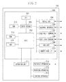
- Fig. 2 is a block diagram illustrating a hardware configuration of the MFP.
- Fig. 3 is a diagram illustrating a software configuration of the MFP.
- Fig. 4 is a sequence chart illustrating an authentication procedure based on card information received from a relay apparatus according to an exemplary embodiment.
- Fig. 5 is a sequence chart illustrating an authentication procedure based on the card information received from a USB host according to the exemplary embodiment.
- Fig. 6 is a flowchart illustrating processing of the MFP.
- Fig. 1 is a diagram illustrating an outline of an authentication system according to the first exemplary embodiment.
- the authentication system includes an MFP 101, an authentication server 102, and a relay apparatus 103 which are communicably connected through a network.
- the MFP 101 is an example of an image forming apparatus. As will be described later in Fig. 2 , the MFP 101 is a multifunctional apparatus that can perform printing, facsimile transmission, and copying according to operations of a log-in user who has been authenticated based on card information.
- the authentication server 102 is an apparatus that performs authentication based on the card information read from an IC card 105.
- the authentication server 102 transfers the card information transmitted from the relay apparatus 103 to the MFP 101, and performs authentication according to an authentication request from the MFP 101.
- the authentication server 102 contains a table that associates IP addresses (or host names) as identification information of MFPs 101 with pieces of information for identifying relay apparatuses 103 on a one-to-one basis. Having such a table, the authentication server 102 can transfer the card information.
- the relay apparatus 103 connects one or a plurality of IC card readers 104 through a USB interface(s) and controls the IC card reader(s) 104.
- the relay apparatus 103 includes a plurality of types of USB host drivers. As a result, the relay apparatus 103 can connect and control IC card readers 104 provided by various third vendors.
- a USB host driver corresponding to an IC card reader 104 transmits commands to the IC card reader 104 for control.
- the relay apparatus 103 is not only connected to an IC card reader (s) 104 through a USB interface(s) but is also connected so that data can be transmitted and received through transmission control protocol/internet protocol (TCP/IP) network communication protocols.
- TCP/IP transmission control protocol/internet protocol
- the relay apparatus 103 transmits the card information to a previously-registered authentication server 102 through the network.
- the card information transmitted to the authentication server 102 includes a user ID and a password for identifying a user, and an ID of a division to which the user belongs.
- the authentication server 102 Upon receiving an authentication request including the card information from the MFP 101, the authentication server 102 accesses authentication information that is managed on the authentication server 102. The authentication server 102 searches for a user name associated with the card information included in the authentication request, and returns an authentication result (OK or NG) to the MFP 101 that has issued the authentication request.
- the present exemplary embodiment deals with the case where the relay apparatus 103 and the authentication server 102 are different apparatuses. However, such a plurality of apparatuses may be integrated into one apparatus.
- the relay apparatus 103 may also have functions as an authentication server 102.
- Fig. 2 is a block diagram illustrating a hardware configuration of the MFP 101 illustrated in Fig. 1 .
- the MFP 101 includes a controller 200, an operation unit 221, a facsimile apparatus 214, a printing apparatus 215, and a reading apparatus 216.
- the controller 200 controls the MFP 101.
- the operation unit 211 accepts user operations.
- the facsimile apparatus 214 transmits and receives facsimile data.
- the printing apparatus 215 prints image data.
- the reading apparatus 216 reads documents.
- the controller 200 includes a central processing unit (CPU) 201, an application specific integrated circuit (ASIC) 202, a north bridge 203, a random access memory (RAM) 212, a read-only memory (ROM) 213, and a hard disk drive (HDD) 218.
- the controller 200 further includes interfaces 204 to 210 intended for data communication with external devices.
- the CPU 201 is a processor that controls the entire apparatus.
- the RAM 212 provides a work area for the CPU 201 and also serves as a memory for temporarily storing image data.
- the ROM 213 contains a program for executing the steps of a flowchart to be described later.
- the network interface 205 is an interface for communicating with the authentication server 102 and other network devices through a network.
- the IEEE 802.1 terminal 207 is an interface to be used in wireless local area network (LAN) communications.
- the USB host 209 is an interface for connecting an IC card reader 104 through a USB cable. Such interfaces are connected to the north bridge 203.
- Fig. 3 is a functional block diagram of the authentication system illustrated in Fig. 1 .
- An authentication server interface (IF) unit 301, an MFP authentication control unit 302, a card information storage unit 303, and a USB host driver 304 illustrated in Fig. 3 are implemented by a control program stored in the ROM 213 being loaded into the RAM 212 and executed by the CPU 201.
- IF authentication server interface
- the authentication server IF unit 301 is a software module for controlling communication between the MFP 101 and the authentication server 102.
- the authentication server IF unit 301 has the following two functions. One is to temporarily store the card information received from the authentication server 102 into the card information storage unit 303. The other is to transmit an authentication request including the card information received from the MFP authentication control unit 302 to the authentication server 102.
- the MFP authentication control unit 302 is a software module for performing processing that is needed for the authentication server 102 to authenticate a user, and managing the state of the MFP 101.
- the MFP authentication control unit 302 checks the card information storage unit 303 for stored card information at predetermined intervals. The card information stored in the card information storage unit 303 has been received through either the network interface 205 or a USB interface. If the card information is stored, the MFP authentication control unit 302 determines whether the MFP 101 is in a state capable of user log-in. If the MFP 101 is in a state capable of user log-in, the MFP authentication control unit 302 requests authentication from the authentication server 102 based on the stored card information.
- the MFP authentication control unit 302 changes the state of the MFP 101 to one where the user associated with the card information has logged in to the MFP 101.
- the MFP 101 executes the print job and performs printing in response to the log-in of the user.
- the MFP authentication control unit 302 notifies the user by on-screen display that the log-in to the MFP 101 is not allowed.
- the card information storage unit 303 is a software module having the function of storing card information received from either one of the authentication server IF unit 301 and the USB host driver 304 into the RAM 212.
- the card information storage unit 303 also has the function of returning the card information according to an acquisition request for the card information from the MFP authentication control unit 302. If the card information storage unit 303 already stores the card information when the card information is transmitted from another module, the card information storage unit 303 overwrites the stored card information with the transmitted card information. In other words, the card information storage unit 303 always stores only the latest card information, not a plurality of pieces of the card information.
- the card information storage unit 303 For example, if the card information storage unit 303 already stores card information received from the USB host driver 304 and then receives new card information from the authentication server IF unit 301, the card information storage unit 303 deletes the card information received from the USB host driver 304. The card information storage unit 303 then stores only the card information received from the authentication server IF unit 301.
- the present exemplary embodiment is configured so that the card information is stored into the same card information storage unit 303 both when the authentication server IF unit 301 receives the card information through the network interface 205 and when the USB host driver 304 receives the card information through the USB host 209.
- the same authentication procedure is performed regardless of where the card information is received from. More specifically, the procedure for transmitting an authentication request based on the card information stored in the card information storage unit 303 and performing processing according to an authentication result is performed according to the common procedure both when the authentication server IF unit 301 receives the card information through the network interface 205 and when the USB host driver 304 receives the card information through the USB host 209.
- Fig. 4 is a sequence chart illustrating a procedure by which the authentication server 102 performs authentication when a user who uses the MFP 101 holds an IC card 105 over an IC card reader 104 that is connected to the network.
- the user holds an IC card 105 over an IC card reader 104.
- the IC card reader 104 reads the card information stored in the IC card 105.
- the IC card reader 104 transmits the read card information to the relay apparatus 103.
- step S402 the relay apparatus 103 transmits the information of the IC card 105 acquired from the IC card reader 104 to a predetermined authentication server 102 through the network.
- step S403 the authentication server 102 notifies the MFP 101 of the information of the IC card 105 transmitted from the relay apparatus 103 as described above. At this point in time, the authentication server 102 will not perform authentication by using the received card information.
- the authentication server IF unit 301 of the MFP 101 identifies and receives data that includes the card information from the authentication server 102 from among a large number of pieces of data transmitted and received over the network.
- the authentication server IF unit 301 once stores the card information received from the authentication server 102 into the card information storage unit 303. If the card information storage unit 303 already stores the card information, the card information storage unit 303 overwrites the stored card information with the new card information received from the authentication server IF unit 301.
- the card information storage unit 303 is configured to store only a single piece of card information.
- the MFP authentication control unit 302 checks the card information storage unit 303 for stored card information at predetermined intervals. If card information is stored, then in step S405, the MFP authentication control unit 302 acquires the card information from the card information storage unit 303. The MFP authentication control unit 302 then checks whether the MFP 101 is in a state capable of authentication (authenticatable state). What an authenticatable state is like will be concretely described later in conjunction with step S603 of Fig. 6 . If the MFP 101 is in an authenticatable state, then in step S407, the MFP authentication control unit 302 transmits an authentication request including the acquired card information to the authentication server 102.
- the authentication server 102 performs authentication based on the card information that is included in the authentication request received from the MFP 101.
- the authentication server 102 transmits the authentication result or an access key issued by the authentication server 102 to the MFP 101.
- the MFP 101 performs log-in and executes a print job in response to the log-in.
- Fig. 5 is a sequence chart illustrating a procedure for authentication processing when card information is received through a USB interface.
- the IC card reader 104 is connected to the relay apparatus 103. The following description will be given on the assumption that an IC card reader different from the IC card reader 104 is connected to the USB host 209 of the MFP 101 through a USB cable.
- step S501 the USB host driver 304 initially acquires card information from the different IC card reader (not illustrated), and stores the acquired card information into the card information storage unit 303. If the card information storage unit 303 already stores card information, the stored card information is deleted and overwritten with the card information transmitted in step S501.
- the MFP authentication control unit 302 checks the card information storage unit 303 for stored card information at predetermined intervals. If card information is stored, then in step S502, the MFP authentication control unit 302 acquires the card information from the card information storage unit 303. The MFP authentication control unit 302 checks whether the MFP 101 is in an authenticatable state. If the MFP 101 is in an authenticatable state, then in step S504, the MFP authentication control unit 302 transmits an authentication request including the card information acquired in step S502 to the authentication server 102.
- the authentication server 102 performs authentication based on the card information that is included in the authentication request received from the MFP 101.
- the authentication server 102 transmits the authentication result or an access key issued by the authentication server 102 to the MFP 101.
- the MFP 101 performs log-in and executes a print job in response to the log-in.
- Steps S502 to S505 of Fig. 5 are processing corresponding to steps S405 to S408 of Fig. 4 .
- Fig. 6 is a flowchart illustrating processing of the MFP authentication control unit 302 of the MFP 101.
- the MFP authentication control unit 302 performs the processing illustrated in Fig. 6 at regular intervals.
- step S601 the MFP authentication control unit 302 initially inquires whether card information is stored in the card information storage unit 303. If the result of the inquiry shows that card information is stored in the card information storage unit 303 (i.e., card information has been written from either the network or the USB host driver 304; YES in step S601), the MFP authentication unit 302 proceeds to step S602.
- the MFP authentication control unit 302 acquires the card information from the card information storage unit 303.
- the acquired card information includes information such as a user ID and a password for identifying a user and an ID of a division to which the user belongs.
- a state incapable of authentication refers to the following: a state where the MFP 101 has already been making an authentication request to the authentication server 102; a state where the MFP 101 has not been operated for certain time and has entered a power conservation state (sleep state); a power saving state; a maintenance state; a state where authentication services of the authentication server 102 are suspended; and a state where a job is under execution.
- a state capable of authentication processing refers to states other than the foregoing. An example is a state where the MFP 101 is on standby.
- step S603 If, in step S603, the MFP 101 is determined to be in an authenticatable state (YES in step S603), the MFP authentication control unit 302 proceeds to processing of step S604. On the other hand, if the MFP 101 is determined not to be in an authenticatable state (NO in step S603), the MFP authentication control unit 302 proceeds to step S607 to delete the card information stored in the card information storage unit 303. Specifically, the MFP authentication control unit 302 issues a command to delete card information to the card information storage unit 303. The card information storage unit 303 deletes the card information according to the command.
- step S603 If, in step S603, the MFP 101 is determined to be in an authenticatable state (YES in step S603), then in step S604, the MFP authentication control unit 302 transmits an authentication request including the card information acquired in step S602 to the authentication server 102. Based on the authentication request transmitted in step S604, the authentication server 102 determines whether to authorize the user who is associated with the card information to use the MFP 101.
- step S605 the MFP authentication control unit 302 receives from the authentication server 102 an authentication result corresponding to the authentication request transmitted in step S604. According to the received authentication result, the MFP authentication control unit 302 then performs predetermined processing such as log-in and execution of a print job in response to the log-in. Upon completing the predetermined processing in step S605, in step S606, the MFP authentication control unit 302 issues a command to delete card information to the card information storage unit 303. According to the command, the card information storage unit 303 deletes the card information.
- the MFP 101 is configured to receive card information read by the IC card reader 104 through the relay apparatus 103 connected to the network.
- a plurality of types of USB device drivers need not be installed in the MFP 101 and the entire system can accept various types of IC card readers as long as the plurality of types of USB device drivers are installed in the relay apparatus 103.
- the present exemplary embodiment is configured so that the card information transmitted from the relay apparatus 103 through the authentication server 102 is stored into the MFP 101, and the MFP 101 requests authentication from the authentication server 102 at timing when the MFP 101 enters a state capable of authentication.
- Such a configuration can prevent an authentication result from being transmitted from the network at timing when the MFP 101 is in a state incapable of authentication.
- the present exemplary embodiment is also configured so that the card information transmitted from the relay apparatus 103 through the network and the card information directly read by the MFP 101 through a USB interface are stored into the common card information storage unit 303. After card information is stored, the same authentication procedure is performed regardless of which interface the card information is received from. For example, suppose that a system that receives card information from a USB interface and performs authentication has already been implemented in a product. Such a product may be simply extended to store card information received from a network interface into the same card information storage unit. This can constitute a configuration like the foregoing exemplary embodiment with a significant reduction in the development cost.
- the MFP 101 is configured to enter the same log-in state both when card information is received through a USB interface and when card information is received through the network. From the user's point of view, authentication performed based on card information that is transferred from the relay apparatus 103 on the network can thus be handled as if the authentication is performed based on card information received through the USB host 209. This precludes confusion of the user.
- the common authentication server 102 performs both the processing of transferring card information in order to notify card information from the relay apparatus 103 to the MFP 101 and the authentication processing according to an authentication request from the MFP 101.
- the processing of transferring card information transmitted from the relay apparatus 103 and the authentication processing according to an authentication request from the MFP 101 may be performed by respective different apparatuses.
- the present exemplary embodiment has dealt with a USB interface as an example of a local interface.
- interfaces other than a USB interface may be used.
- the IEEE 802.1 terminal 207 intended for wireless LAN and the IEEE 1394 terminal 208 for connecting a computer to peripheral equipment, illustrated in Fig. 2 may be used.
- the present exemplary embodiment has dealt with examples of the cases where card information is received through a local interface and where card information is received through a network interface.
- the interfaces are not limited thereto as long as the two interfaces are of respective different types.
- aspects of the present invention can also be realized by a computer of a system or apparatus (or devices such as a CPU or MPU) that reads out and executes a program recorded on a memory device to perform the functions of the above-described embodiments, and by a method, the steps of which are performed by a computer of a system or apparatus by, for example, reading out and executing a program recorded on a memory device to perform the functions of the above-described embodiments.
- the program is provided to the computer for example via a network or from a recording medium of various types serving as the memory device (e.g., non-transitory computer-readable medium).
- the system or apparatus, and the recording medium where the program is stored are included as being within the scope of the present invention.
- An image forming apparatus (101) configured to communicate with an authentication apparatus (102) through a network, the image forming apparatus (101) including: an acquisition means configured to acquire a user ID through the network; a transmission means configured, when the user ID is acquired by the acquisition means, to transmit an authentication request including a user ID to the authentication apparatus (102) through the network; and a control means(201,302) configured to allow the user to log in to the image forming apparatus (101) according to an authentication result in response to the transmitted authentication request.
Landscapes
- Engineering & Computer Science (AREA)
- Computer Security & Cryptography (AREA)
- Computer Hardware Design (AREA)
- General Engineering & Computer Science (AREA)
- Theoretical Computer Science (AREA)
- Signal Processing (AREA)
- Computer Networks & Wireless Communication (AREA)
- Computing Systems (AREA)
- Physics & Mathematics (AREA)
- General Physics & Mathematics (AREA)
- Software Systems (AREA)
- Health & Medical Sciences (AREA)
- Bioethics (AREA)
- General Health & Medical Sciences (AREA)
- Multimedia (AREA)
- Facsimiles In General (AREA)
- Accessory Devices And Overall Control Thereof (AREA)
Abstract
Description
- The present invention relates to a network authentication system which performs authentication of a user who uses an image forming apparatus based on user information received through a network.
- A user authentication system for an image forming apparatus including a conventional print function and facsimile function performs authentication using an integrated circuit (IC) card, for example. According to such an authentication system, an IC card is used to perform authentication by using a user identifier (ID) associated with card information on the IC card and log in to the image forming apparatus. In the user authentication system, card information including user information is stored in a storage medium such as an IC card. The card information read from an IC card reader corresponding to the IC card is used for user authentication.
- Japanese Patent Application Laid-Open No.
2009-93626 - The present invention is directed to providing an image forming apparatus that suitably performs authentication based on information received through a network interface.
- The present invention in its first aspect provides an image forming apparatus as specified in
claims 1 to 9. - The present invention in its second aspect provides an image forming apparatus as specified in claims 10 to 17.
- The present invention in its third aspect provides a network system as specified in claims 18 to 27.
- The present invention in its forth aspect provides a method of controlling an image forming apparatus as specified in claim 28.
- The present invention in its sixth aspect provides a method of controlling an image forming apparatus as specified in claim 29.
- The present invention in its seventh aspect provides a method of controlling an image forming apparatus as specified in claim 30.
- The present invention in its eighth aspect provides a program as specified in claim 31.
- The present invention in its ninth aspect provides a program as specified in claim 32.
- Further features and aspects of the present invention will become apparent from the following detailed description of exemplary embodiments with reference to the attached drawings.
- The accompanying drawings, which are incorporated in and constitute a part of the specification, illustrate exemplary embodiments, features, and aspects of the invention and, together with the description, serve to explain the principles of the invention.
-
Fig. 1 is a schematic diagram illustrating an authentication system that includes a multi function peripheral (MFP) (image forming apparatus), a card reader, and an authentication server. -
Fig. 2 is a block diagram illustrating a hardware configuration of the MFP. -
Fig. 3 is a diagram illustrating a software configuration of the MFP. -
Fig. 4 is a sequence chart illustrating an authentication procedure based on card information received from a relay apparatus according to an exemplary embodiment. -
Fig. 5 is a sequence chart illustrating an authentication procedure based on the card information received from a USB host according to the exemplary embodiment. -
Fig. 6 is a flowchart illustrating processing of the MFP. - Various exemplary embodiments, features, and aspects of the invention will be described in detail below with reference to the drawings.
- A first exemplary embodiment will be described.
Fig. 1 is a diagram illustrating an outline of an authentication system according to the first exemplary embodiment. The authentication system includes anMFP 101, anauthentication server 102, and arelay apparatus 103 which are communicably connected through a network. - The
MFP 101 is an example of an image forming apparatus. As will be described later inFig. 2 , theMFP 101 is a multifunctional apparatus that can perform printing, facsimile transmission, and copying according to operations of a log-in user who has been authenticated based on card information. - The
authentication server 102 is an apparatus that performs authentication based on the card information read from anIC card 105. Theauthentication server 102 transfers the card information transmitted from therelay apparatus 103 to theMFP 101, and performs authentication according to an authentication request from theMFP 101. - The
authentication server 102 contains a table that associates IP addresses (or host names) as identification information ofMFPs 101 with pieces of information for identifyingrelay apparatuses 103 on a one-to-one basis. Having such a table, theauthentication server 102 can transfer the card information. - The
relay apparatus 103 connects one or a plurality ofIC card readers 104 through a USB interface(s) and controls the IC card reader(s) 104. Therelay apparatus 103 includes a plurality of types of USB host drivers. As a result, therelay apparatus 103 can connect and controlIC card readers 104 provided by various third vendors. A USB host driver corresponding to anIC card reader 104 transmits commands to theIC card reader 104 for control. Therelay apparatus 103 is not only connected to an IC card reader (s) 104 through a USB interface(s) but is also connected so that data can be transmitted and received through transmission control protocol/internet protocol (TCP/IP) network communication protocols. When anIC card reader 104 reads the card information stored in anIC card 105, therelay apparatus 103 transmits the card information to a previously-registeredauthentication server 102 through the network. The card information transmitted to theauthentication server 102 includes a user ID and a password for identifying a user, and an ID of a division to which the user belongs. - Upon receiving an authentication request including the card information from the
MFP 101, theauthentication server 102 accesses authentication information that is managed on theauthentication server 102. Theauthentication server 102 searches for a user name associated with the card information included in the authentication request, and returns an authentication result (OK or NG) to theMFP 101 that has issued the authentication request. - The present exemplary embodiment deals with the case where the
relay apparatus 103 and theauthentication server 102 are different apparatuses. However, such a plurality of apparatuses may be integrated into one apparatus. For example, therelay apparatus 103 may also have functions as anauthentication server 102. -
Fig. 2 is a block diagram illustrating a hardware configuration of theMFP 101 illustrated inFig. 1 . - The
MFP 101 includes acontroller 200, an operation unit 221, afacsimile apparatus 214, aprinting apparatus 215, and areading apparatus 216. Thecontroller 200 controls theMFP 101. Theoperation unit 211 accepts user operations. Thefacsimile apparatus 214 transmits and receives facsimile data. Theprinting apparatus 215 prints image data. Thereading apparatus 216 reads documents. - The
controller 200 includes a central processing unit (CPU) 201, an application specific integrated circuit (ASIC) 202, anorth bridge 203, a random access memory (RAM) 212, a read-only memory (ROM) 213, and a hard disk drive (HDD) 218. Thecontroller 200 further includesinterfaces 204 to 210 intended for data communication with external devices. - The
CPU 201 is a processor that controls the entire apparatus. TheRAM 212 provides a work area for theCPU 201 and also serves as a memory for temporarily storing image data. TheROM 213 contains a program for executing the steps of a flowchart to be described later. - The
network interface 205 is an interface for communicating with theauthentication server 102 and other network devices through a network. The IEEE 802.1terminal 207 is an interface to be used in wireless local area network (LAN) communications. TheUSB host 209 is an interface for connecting anIC card reader 104 through a USB cable. Such interfaces are connected to thenorth bridge 203. -
Fig. 3 is a functional block diagram of the authentication system illustrated inFig. 1 . An authentication server interface (IF)unit 301, an MFPauthentication control unit 302, a cardinformation storage unit 303, and aUSB host driver 304 illustrated inFig. 3 are implemented by a control program stored in theROM 213 being loaded into theRAM 212 and executed by theCPU 201. - The authentication server IF
unit 301 is a software module for controlling communication between theMFP 101 and theauthentication server 102. The authentication server IFunit 301 has the following two functions. One is to temporarily store the card information received from theauthentication server 102 into the cardinformation storage unit 303. The other is to transmit an authentication request including the card information received from the MFPauthentication control unit 302 to theauthentication server 102. - The MFP
authentication control unit 302 is a software module for performing processing that is needed for theauthentication server 102 to authenticate a user, and managing the state of theMFP 101. - Specifically, the MFP
authentication control unit 302 checks the cardinformation storage unit 303 for stored card information at predetermined intervals. The card information stored in the cardinformation storage unit 303 has been received through either thenetwork interface 205 or a USB interface. If the card information is stored, the MFPauthentication control unit 302 determines whether theMFP 101 is in a state capable of user log-in. If theMFP 101 is in a state capable of user log-in, the MFPauthentication control unit 302 requests authentication from theauthentication server 102 based on the stored card information. - Subsequently, upon receiving an authentication result that indicates "OK" (i.e., successful authentication) from the
authentication server 102, the MFPauthentication control unit 302 changes the state of theMFP 101 to one where the user associated with the card information has logged in to theMFP 101. - If the
HDD 218 or an external storage device (not illustrated) contains a print job pertaining to the log-in user in an authentication wait state, theMFP 101 executes the print job and performs printing in response to the log-in of the user. - Now, if the authentication result received from the
authentication server 102 indicates "NO" (i.e., failed authentication), the MFPauthentication control unit 302 notifies the user by on-screen display that the log-in to theMFP 101 is not allowed. - The card
information storage unit 303 is a software module having the function of storing card information received from either one of the authentication server IFunit 301 and theUSB host driver 304 into theRAM 212. The cardinformation storage unit 303 also has the function of returning the card information according to an acquisition request for the card information from the MFPauthentication control unit 302. If the cardinformation storage unit 303 already stores the card information when the card information is transmitted from another module, the cardinformation storage unit 303 overwrites the stored card information with the transmitted card information. In other words, the cardinformation storage unit 303 always stores only the latest card information, not a plurality of pieces of the card information. For example, if the cardinformation storage unit 303 already stores card information received from theUSB host driver 304 and then receives new card information from the authentication server IFunit 301, the cardinformation storage unit 303 deletes the card information received from theUSB host driver 304. The cardinformation storage unit 303 then stores only the card information received from the authentication server IFunit 301. - The present exemplary embodiment is configured so that the card information is stored into the same card
information storage unit 303 both when the authentication server IFunit 301 receives the card information through thenetwork interface 205 and when theUSB host driver 304 receives the card information through theUSB host 209. Once the card information is stored in the cardinformation storage unit 303, the same authentication procedure is performed regardless of where the card information is received from. More specifically, the procedure for transmitting an authentication request based on the card information stored in the cardinformation storage unit 303 and performing processing according to an authentication result is performed according to the common procedure both when the authentication server IFunit 301 receives the card information through thenetwork interface 205 and when theUSB host driver 304 receives the card information through theUSB host 209. -
Fig. 4 is a sequence chart illustrating a procedure by which theauthentication server 102 performs authentication when a user who uses theMFP 101 holds anIC card 105 over anIC card reader 104 that is connected to the network. - Initially, the user holds an
IC card 105 over anIC card reader 104. TheIC card reader 104 reads the card information stored in theIC card 105. In step S401, theIC card reader 104 transmits the read card information to therelay apparatus 103. - In step S402, the
relay apparatus 103 transmits the information of theIC card 105 acquired from theIC card reader 104 to apredetermined authentication server 102 through the network. In step S403, theauthentication server 102 notifies theMFP 101 of the information of theIC card 105 transmitted from therelay apparatus 103 as described above. At this point in time, theauthentication server 102 will not perform authentication by using the received card information. - The authentication server IF
unit 301 of theMFP 101 identifies and receives data that includes the card information from theauthentication server 102 from among a large number of pieces of data transmitted and received over the network. In step S404, the authentication server IFunit 301 once stores the card information received from theauthentication server 102 into the cardinformation storage unit 303. If the cardinformation storage unit 303 already stores the card information, the cardinformation storage unit 303 overwrites the stored card information with the new card information received from the authentication server IFunit 301. In other words, the cardinformation storage unit 303 is configured to store only a single piece of card information. - The MFP
authentication control unit 302 checks the cardinformation storage unit 303 for stored card information at predetermined intervals. If card information is stored, then in step S405, the MFPauthentication control unit 302 acquires the card information from the cardinformation storage unit 303. The MFPauthentication control unit 302 then checks whether theMFP 101 is in a state capable of authentication (authenticatable state). What an authenticatable state is like will be concretely described later in conjunction with step S603 ofFig. 6 . If theMFP 101 is in an authenticatable state, then in step S407, the MFPauthentication control unit 302 transmits an authentication request including the acquired card information to theauthentication server 102. - The
authentication server 102 performs authentication based on the card information that is included in the authentication request received from theMFP 101. In step S408, theauthentication server 102 transmits the authentication result or an access key issued by theauthentication server 102 to theMFP 101. According to the authentication result received, theMFP 101 performs log-in and executes a print job in response to the log-in. -
Fig. 5 is a sequence chart illustrating a procedure for authentication processing when card information is received through a USB interface. In the system configuration illustrated inFig. 1 , theIC card reader 104 is connected to therelay apparatus 103. The following description will be given on the assumption that an IC card reader different from theIC card reader 104 is connected to theUSB host 209 of theMFP 101 through a USB cable. - In step S501, the
USB host driver 304 initially acquires card information from the different IC card reader (not illustrated), and stores the acquired card information into the cardinformation storage unit 303. If the cardinformation storage unit 303 already stores card information, the stored card information is deleted and overwritten with the card information transmitted in step S501. - Next, the MFP
authentication control unit 302 checks the cardinformation storage unit 303 for stored card information at predetermined intervals. If card information is stored, then in step S502, the MFPauthentication control unit 302 acquires the card information from the cardinformation storage unit 303. The MFPauthentication control unit 302 checks whether theMFP 101 is in an authenticatable state. If theMFP 101 is in an authenticatable state, then in step S504, the MFPauthentication control unit 302 transmits an authentication request including the card information acquired in step S502 to theauthentication server 102. - The
authentication server 102 performs authentication based on the card information that is included in the authentication request received from theMFP 101. In step S505, theauthentication server 102 transmits the authentication result or an access key issued by theauthentication server 102 to theMFP 101. According to the authentication result received, theMFP 101 performs log-in and executes a print job in response to the log-in. - Steps S502 to S505 of
Fig. 5 are processing corresponding to steps S405 to S408 ofFig. 4 . -
Fig. 6 is a flowchart illustrating processing of the MFPauthentication control unit 302 of theMFP 101. The MFPauthentication control unit 302 performs the processing illustrated inFig. 6 at regular intervals. - In step S601, the MFP
authentication control unit 302 initially inquires whether card information is stored in the cardinformation storage unit 303. If the result of the inquiry shows that card information is stored in the card information storage unit 303 (i.e., card information has been written from either the network or theUSB host driver 304; YES in step S601), theMFP authentication unit 302 proceeds to step S602. - In step S602, the MFP
authentication control unit 302 acquires the card information from the cardinformation storage unit 303. As described previously, the acquired card information includes information such as a user ID and a password for identifying a user and an ID of a division to which the user belongs. - In step S603, the MFP
authentication control unit 302 determines whether theMFP 101 is in a state capable of authentication (authenticatable state) or a state incapable of authentication. In the present exemplary embodiment, a state incapable of authentication refers to the following: a state where theMFP 101 has already been making an authentication request to theauthentication server 102; a state where theMFP 101 has not been operated for certain time and has entered a power conservation state (sleep state); a power saving state; a maintenance state; a state where authentication services of theauthentication server 102 are suspended; and a state where a job is under execution. On the other hand, a state capable of authentication processing (authenticatable state) refers to states other than the foregoing. An example is a state where theMFP 101 is on standby. - If, in step S603, the
MFP 101 is determined to be in an authenticatable state (YES in step S603), the MFPauthentication control unit 302 proceeds to processing of step S604. On the other hand, if theMFP 101 is determined not to be in an authenticatable state (NO in step S603), the MFPauthentication control unit 302 proceeds to step S607 to delete the card information stored in the cardinformation storage unit 303. Specifically, the MFPauthentication control unit 302 issues a command to delete card information to the cardinformation storage unit 303. The cardinformation storage unit 303 deletes the card information according to the command. - If, in step S603, the
MFP 101 is determined to be in an authenticatable state (YES in step S603), then in step S604, the MFPauthentication control unit 302 transmits an authentication request including the card information acquired in step S602 to theauthentication server 102. Based on the authentication request transmitted in step S604, theauthentication server 102 determines whether to authorize the user who is associated with the card information to use theMFP 101. - In step S605, the MFP
authentication control unit 302 receives from theauthentication server 102 an authentication result corresponding to the authentication request transmitted in step S604. According to the received authentication result, the MFPauthentication control unit 302 then performs predetermined processing such as log-in and execution of a print job in response to the log-in. Upon completing the predetermined processing in step S605, in step S606, the MFPauthentication control unit 302 issues a command to delete card information to the cardinformation storage unit 303. According to the command, the cardinformation storage unit 303 deletes the card information. - As described above, the
MFP 101 according to the present exemplary embodiment is configured to receive card information read by theIC card reader 104 through therelay apparatus 103 connected to the network. With such a configuration, a plurality of types of USB device drivers need not be installed in theMFP 101 and the entire system can accept various types of IC card readers as long as the plurality of types of USB device drivers are installed in therelay apparatus 103. - The present exemplary embodiment is configured so that the card information transmitted from the
relay apparatus 103 through theauthentication server 102 is stored into theMFP 101, and theMFP 101 requests authentication from theauthentication server 102 at timing when theMFP 101 enters a state capable of authentication. Such a configuration can prevent an authentication result from being transmitted from the network at timing when theMFP 101 is in a state incapable of authentication. - The present exemplary embodiment is also configured so that the card information transmitted from the
relay apparatus 103 through the network and the card information directly read by theMFP 101 through a USB interface are stored into the common cardinformation storage unit 303. After card information is stored, the same authentication procedure is performed regardless of which interface the card information is received from. For example, suppose that a system that receives card information from a USB interface and performs authentication has already been implemented in a product. Such a product may be simply extended to store card information received from a network interface into the same card information storage unit. This can constitute a configuration like the foregoing exemplary embodiment with a significant reduction in the development cost. - The
MFP 101 according to the present exemplary embodiment is configured to enter the same log-in state both when card information is received through a USB interface and when card information is received through the network. From the user's point of view, authentication performed based on card information that is transferred from therelay apparatus 103 on the network can thus be handled as if the authentication is performed based on card information received through theUSB host 209. This precludes confusion of the user. - In the present exemplary embodiment, the
common authentication server 102 performs both the processing of transferring card information in order to notify card information from therelay apparatus 103 to theMFP 101 and the authentication processing according to an authentication request from theMFP 101. However, the processing of transferring card information transmitted from therelay apparatus 103 and the authentication processing according to an authentication request from theMFP 101 may be performed by respective different apparatuses. - The present exemplary embodiment has dealt with a USB interface as an example of a local interface. However, interfaces other than a USB interface may be used. For example, the IEEE 802.1 terminal 207 intended for wireless LAN and the
IEEE 1394terminal 208 for connecting a computer to peripheral equipment, illustrated inFig. 2 , may be used. - The present exemplary embodiment has dealt with examples of the cases where card information is received through a local interface and where card information is received through a network interface. The interfaces are not limited thereto as long as the two interfaces are of respective different types. Other Embodiments
- Aspects of the present invention can also be realized by a computer of a system or apparatus (or devices such as a CPU or MPU) that reads out and executes a program recorded on a memory device to perform the functions of the above-described embodiments, and by a method, the steps of which are performed by a computer of a system or apparatus by, for example, reading out and executing a program recorded on a memory device to perform the functions of the above-described embodiments. For this purpose, the program is provided to the computer for example via a network or from a recording medium of various types serving as the memory device (e.g., non-transitory computer-readable medium). In such a case, the system or apparatus, and the recording medium where the program is stored, are included as being within the scope of the present invention.
- While the present invention has been described with reference to exemplary embodiments, it is to be understood that the invention is not limited to the disclosed exemplary embodiments. The scope of the following claims is to be accorded the broadest interpretation so as to encompass all modifications, equivalent structures, and functions.
An image forming apparatus (101) configured to communicate with an authentication apparatus (102) through a network, the image forming apparatus (101) including: an acquisition means configured to acquire a user ID through the network; a transmission means configured, when the user ID is acquired by the acquisition means, to transmit an authentication request including a user ID to the authentication apparatus (102) through the network; and a control means(201,302) configured to allow the user to log in to the image forming apparatus (101) according to an authentication result in response to the transmitted authentication request.
Claims (11)
- An image forming apparatus (101) comprising:a network interface (205);a local interface (209);a storage means (212,303) configured to store a user identifier (ID) received from the network interface (205) or the local interface(209); anda control means (201,302) configured to transmit an authentication request including the user ID stored in the storage means (212,303) to an authentication apparatus (102) and allow a user corresponding to the user ID to log in based on an authentication result received from the authentication apparatus (102),wherein the control means (201,302) is configured to perform control so that a user ID received from the network interface (205) and a user ID received from the local interface (209) are stored into the common storage means (212,303).
- The image forming apparatus (101) according to claim 1, wherein the control means (201,302) is configured, when a user ID is received from the network interface (205) while a user ID received from the local interface (209) has been stored in the storage means (212,303), to overwrite the user ID stored in the storage means (212,303) with the user ID received from the network interface (205).
- The image forming apparatus (101) according to claims 1 or 2, further comprising an execution means (215) configured to execute a print job of a user in response to log-in of the user.
- The image forming apparatus (101) according to any one of claims 1 to 3, wherein the network interface (205) receives card information including the user ID from a relay apparatus (103) connected to a card reader (104).
- The image forming apparatus (101) according to any one of claims 1 to 4, wherein the local interface (209) is connected to a card reader (104) and receives card information including the user ID from the card reader (104).
- The image forming apparatus (101) according to claims 4 or 5, wherein the card information further includes a password and a division ID.
- The image forming apparatus (101) according to any one of claims 1 to 6, wherein the local interface (209) is an interface configured to perform data communication according to a universal serial bus (USB) protocol.
- The image forming apparatus (101) according to any one of claims 1 to 7, wherein the control means (201,302) is configured, when the image forming apparatus (101) is in a standby state, to transmit the authentication request.
- The image forming apparatus (101) according to any one of claims 1 to 8, wherein the control means (201,302) is configured, when the image forming apparatus (101) is in a power saving state or a maintenance state, to delete the user ID stored in the storage means (212,303).
- A method of controlling an image forming apparatus (101), the method comprising:receiving a user ID from a network interface (205)or a local interface (209) (step S403, S501);storing the user ID received by the receiving (step S403) into a storage device (213) (step S404, S501); andperforming control to transmit an authentication request including the user ID stored in the storage device (213) to an authentication apparatus (102) and allow a user corresponding to the user ID to log in based on an authentication result received from the authentication apparatus (102) (step S604, S605),wherein the performing of control (step S604, S605) includes performing control so that the user ID received from the network interface (205)and the user ID received from the local interface (209) are stored into the common storage device (213).
- A program for causing a computer to perform operations comprising:receiving a user ID from a network interface (205) or a local interface (209) (step S403, S501);storing the user ID received by the receiving (step S403, S501) into a storage device (213) (step S404, S501); andperforming control to transmit an authentication request including the user ID stored in the storage device (213) to an authentication apparatus (102) and allow a user corresponding to the user ID to log in based on an authentication result received from the authentication apparatus (102) (step S604, S605),wherein the performing of control (step S604, S605) includes performing control so that the user ID received from the network interface (205)and the user ID received from the local interface (209) are stored into the common storage device (213).
Applications Claiming Priority (1)
| Application Number | Priority Date | Filing Date | Title |
|---|---|---|---|
| JP2011150891A JP5766051B2 (en) | 2011-07-07 | 2011-07-07 | Image processing device capable of communicating with external device, control method of image processing device, and program |
Publications (2)
| Publication Number | Publication Date |
|---|---|
| EP2544426A1 true EP2544426A1 (en) | 2013-01-09 |
| EP2544426B1 EP2544426B1 (en) | 2020-02-05 |
Family
ID=46548214
Family Applications (1)
| Application Number | Title | Priority Date | Filing Date |
|---|---|---|---|
| EP12175244.8A Active EP2544426B1 (en) | 2011-07-07 | 2012-07-06 | Image forming apparatus communicating with external device through network, network system, method of controlling image forming apparatus, program, and storage medium |
Country Status (5)
| Country | Link |
|---|---|
| US (1) | US10032013B2 (en) |
| EP (1) | EP2544426B1 (en) |
| JP (1) | JP5766051B2 (en) |
| KR (1) | KR101565201B1 (en) |
| CN (1) | CN103106360B (en) |
Cited By (2)
| Publication number | Priority date | Publication date | Assignee | Title |
|---|---|---|---|---|
| WO2014112699A1 (en) * | 2013-01-17 | 2014-07-24 | Samsung Electronics Co., Ltd. | Image forming apparatus, method of connecting with external device thereof, and computer-readable recording medium |
| US20230004634A1 (en) * | 2021-06-30 | 2023-01-05 | Brother Kogyo Kabushiki Kaisha | Management system, device, device management method, controlling method, and non-transitory computer-readable recording medium therefor |
Families Citing this family (16)
| Publication number | Priority date | Publication date | Assignee | Title |
|---|---|---|---|---|
| JP6398153B2 (en) * | 2013-06-04 | 2018-10-03 | 株式会社リコー | Apparatus, information processing terminal, information processing system, display control method, and program |
| JP6176020B2 (en) | 2013-09-17 | 2017-08-09 | 株式会社リコー | Apparatus, information processing system, information processing method, information processing program, and storage medium storing information processing program |
| JP6346443B2 (en) * | 2014-01-08 | 2018-06-20 | キヤノン株式会社 | Information processing apparatus, control method therefor, and program |
| CN104834853B (en) * | 2015-04-30 | 2017-11-21 | 北京立思辰计算机技术有限公司 | A kind of personal identification method, device and information security type duplicator |
| DE102015011076A1 (en) * | 2015-08-24 | 2017-03-02 | Giesecke & Devrient Gmbh | transaction system |
| US10517021B2 (en) | 2016-06-30 | 2019-12-24 | Evolve Cellular Inc. | Long term evolution-primary WiFi (LTE-PW) |
| JP6821377B2 (en) | 2016-10-11 | 2021-01-27 | キヤノン株式会社 | Image reader and image forming device |
| JP6838922B2 (en) | 2016-10-11 | 2021-03-03 | キヤノン株式会社 | Image reader and image forming device |
| JP6849378B2 (en) | 2016-10-11 | 2021-03-24 | キヤノン株式会社 | Image reader and image forming device |
| JP6759044B2 (en) * | 2016-10-11 | 2020-09-23 | キヤノン株式会社 | Image reader and image forming device |
| JP6821378B2 (en) | 2016-10-11 | 2021-01-27 | キヤノン株式会社 | Image reader and image forming device |
| US10542168B2 (en) | 2016-10-11 | 2020-01-21 | Canon Kabushiki Kaisha | Image reading device and image forming apparatus |
| US20180357411A1 (en) * | 2017-06-13 | 2018-12-13 | Ca, Inc. | Authentication Of A Device |
| JP6843723B2 (en) | 2017-09-29 | 2021-03-17 | シャープ株式会社 | Server equipment, server client system and programs |
| US11061144B2 (en) * | 2018-01-30 | 2021-07-13 | Valmont Industries, Inc. | System and method for GPS alignment using real-time kinetics |
| JP7139757B2 (en) * | 2018-07-27 | 2022-09-21 | 株式会社リコー | Information processing device, authentication method, program |
Citations (3)
| Publication number | Priority date | Publication date | Assignee | Title |
|---|---|---|---|---|
| JP2009093626A (en) | 2007-09-18 | 2009-04-30 | Canon Marketing Japan Inc | Image forming apparatus, authentication system, authentication method, program, and computer-readable storage medium |
| US20090109476A1 (en) * | 2007-10-30 | 2009-04-30 | Canon Kabushiki Kaisha | Image forming apparatus, printing system, printing method and program |
| US20100079805A1 (en) * | 2008-09-30 | 2010-04-01 | Canon Kabushiki Kaisha | Network interface apparatus, control method, program, and image forming apparatus |
Family Cites Families (16)
| Publication number | Priority date | Publication date | Assignee | Title |
|---|---|---|---|---|
| US7743262B2 (en) * | 1997-07-15 | 2010-06-22 | Silverbrook Research Pty Ltd | Integrated circuit incorporating protection from power supply attacks |
| US7454796B2 (en) * | 2000-12-22 | 2008-11-18 | Canon Kabushiki Kaisha | Obtaining temporary exclusive control of a printing device |
| US7580180B2 (en) * | 2002-03-21 | 2009-08-25 | Sipix Imaging, Inc. | Magnetophoretic and electromagnetophoretic displays |
| JP4020851B2 (en) * | 2003-10-15 | 2007-12-12 | 日立マクセル株式会社 | Information recording method and information recording medium |
| JP3840244B2 (en) * | 2003-11-12 | 2006-11-01 | キヤノン株式会社 | Printing apparatus, job processing method, storage medium, program |
| JP2005327123A (en) * | 2004-05-14 | 2005-11-24 | Seiko Epson Corp | Print job authentication apparatus, printer with authentication function, printer management server, authentication print program, authentication print method, and authentication print system |
| US20070091346A1 (en) * | 2005-10-25 | 2007-04-26 | Kabushiki Kaisha Toshiba | Network print system |
| US20070107042A1 (en) * | 2005-11-04 | 2007-05-10 | Fatima Corona | System and method for limiting access to a shared multi-functional peripheral device |
| US20090180141A1 (en) * | 2008-01-11 | 2009-07-16 | Kyocera Mita | Image Forming Apparatus, Charge Server and Image Forming System |
| JP5359127B2 (en) | 2008-08-29 | 2013-12-04 | 株式会社リコー | Authentication control apparatus, authentication control method, and program |
| CN102282832B (en) * | 2009-01-15 | 2015-03-25 | 日本电气株式会社 | Mobile communication system, mobile station apparatus, base station apparatus, and communication control method |
| JP5339443B2 (en) | 2009-05-25 | 2013-11-13 | キヤノンマーケティングジャパン株式会社 | Authentication information management system, image forming apparatus, authentication server, and processing method and program thereof |
| JP5354665B2 (en) * | 2009-06-01 | 2013-11-27 | キヤノンマーケティングジャパン株式会社 | Image forming apparatus, authentication system, authentication method, and program |
| JP2011170544A (en) * | 2010-02-17 | 2011-09-01 | Sharp Corp | Software distribution method, installation method, information processing apparatus, and software distribution system |
| EP2980695B1 (en) * | 2010-05-09 | 2017-04-12 | Citrix Systems, Inc. | Methods and systems for forcing an application to store data in a secure storage location |
| JP2010272137A (en) | 2010-08-11 | 2010-12-02 | Ricoh Co Ltd | Printing system, printing method, print data storage device, control device, print data storage program, and control program |
-
2011
- 2011-07-07 JP JP2011150891A patent/JP5766051B2/en not_active Expired - Fee Related
-
2012
- 2012-07-03 US US13/541,358 patent/US10032013B2/en not_active Expired - Fee Related
- 2012-07-06 EP EP12175244.8A patent/EP2544426B1/en active Active
- 2012-07-06 CN CN201210234562.3A patent/CN103106360B/en not_active Expired - Fee Related
- 2012-07-06 KR KR1020120073646A patent/KR101565201B1/en not_active Expired - Fee Related
Patent Citations (4)
| Publication number | Priority date | Publication date | Assignee | Title |
|---|---|---|---|---|
| JP2009093626A (en) | 2007-09-18 | 2009-04-30 | Canon Marketing Japan Inc | Image forming apparatus, authentication system, authentication method, program, and computer-readable storage medium |
| US20100050247A1 (en) * | 2007-09-18 | 2010-02-25 | Canon Kabushiki Kaisha | Authentication system and method including image forming apparatus |
| US20090109476A1 (en) * | 2007-10-30 | 2009-04-30 | Canon Kabushiki Kaisha | Image forming apparatus, printing system, printing method and program |
| US20100079805A1 (en) * | 2008-09-30 | 2010-04-01 | Canon Kabushiki Kaisha | Network interface apparatus, control method, program, and image forming apparatus |
Cited By (3)
| Publication number | Priority date | Publication date | Assignee | Title |
|---|---|---|---|---|
| WO2014112699A1 (en) * | 2013-01-17 | 2014-07-24 | Samsung Electronics Co., Ltd. | Image forming apparatus, method of connecting with external device thereof, and computer-readable recording medium |
| US9547504B2 (en) | 2013-01-17 | 2017-01-17 | Samsung Electronics Co., Ltd. | Image forming apparatus, method of connecting with external device thereof, and computer-readable recording medium |
| US20230004634A1 (en) * | 2021-06-30 | 2023-01-05 | Brother Kogyo Kabushiki Kaisha | Management system, device, device management method, controlling method, and non-transitory computer-readable recording medium therefor |
Also Published As
| Publication number | Publication date |
|---|---|
| US10032013B2 (en) | 2018-07-24 |
| JP2013020303A (en) | 2013-01-31 |
| CN103106360B (en) | 2017-12-05 |
| KR20130006356A (en) | 2013-01-16 |
| CN103106360A (en) | 2013-05-15 |
| US20130014240A1 (en) | 2013-01-10 |
| EP2544426B1 (en) | 2020-02-05 |
| JP5766051B2 (en) | 2015-08-19 |
| KR101565201B1 (en) | 2015-11-02 |
Similar Documents
| Publication | Publication Date | Title |
|---|---|---|
| EP2544426B1 (en) | Image forming apparatus communicating with external device through network, network system, method of controlling image forming apparatus, program, and storage medium | |
| US8836981B2 (en) | Apparatus, system, and method of output distribution, and recording medium storing output distribution control program | |
| JP5046781B2 (en) | Authentication system, authentication control method, image forming apparatus, and authentication server apparatus | |
| US20100208298A1 (en) | Image forming apparatus | |
| EP2284760A2 (en) | Information processing system and control method thereof, and program | |
| JP6399771B2 (en) | Information processing apparatus, control method thereof, and program | |
| US9602684B2 (en) | Image forming apparatus, method for controlling remote operation, and storage medium | |
| US20170308343A1 (en) | Printing system, a method of printing a print job, and a program | |
| US9300648B2 (en) | Image processing apparatus and image processing system | |
| US8683124B2 (en) | Device, control method thereof, and program | |
| US20160080588A1 (en) | Information processing system, information processing method, and recording medium storing an information processing program | |
| EP4064024A1 (en) | Information processing system, image forming apparatus, program, and information processing method | |
| JP5949007B2 (en) | Job execution apparatus, program, and execution control method | |
| US20140355035A1 (en) | Non-Transitory Storage Medium Storing Instructions, Information Processing Device, Image Processing Apparatus, and Image Processing System | |
| US20060034234A1 (en) | Wireless network system, wireless communication device and connection set-up method | |
| US9317231B2 (en) | Image forming apparatus, information processing apparatus, control method thereof, and storage medium | |
| US9525757B2 (en) | Information processing apparatus that controls connection of devices, method of controlling the apparatus, and device control system | |
| US20140118766A1 (en) | Host device, driving method of the host device, image forming device, image forming method, and computer-readable recording medium | |
| US8832826B2 (en) | Image forming apparatus, method for controlling image forming apparatus, and program | |
| JP2013251703A (en) | Distribution system of image information, control program and control method | |
| JP2016225824A (en) | Information processing system, information processing apparatus, and information processing method | |
| JP2007193407A (en) | Printing system and printing apparatus | |
| US9268726B2 (en) | Information processing apparatus, control method thereof, and storage medium | |
| JP4431695B2 (en) | Printer connection device and network printing system | |
| US20230092279A1 (en) | Printing system, print server, and printing control method |
Legal Events
| Date | Code | Title | Description |
|---|---|---|---|
| PUAI | Public reference made under article 153(3) epc to a published international application that has entered the european phase |
Free format text: ORIGINAL CODE: 0009012 |
|
| AK | Designated contracting states |
Kind code of ref document: A1 Designated state(s): AL AT BE BG CH CY CZ DE DK EE ES FI FR GB GR HR HU IE IS IT LI LT LU LV MC MK MT NL NO PL PT RO RS SE SI SK SM TR |
|
| AX | Request for extension of the european patent |
Extension state: BA ME |
|
| 17P | Request for examination filed |
Effective date: 20130709 |
|
| RBV | Designated contracting states (corrected) |
Designated state(s): AL AT BE BG CH CY CZ DE DK EE ES FI FR GB GR HR HU IE IS IT LI LT LU LV MC MK MT NL NO PL PT RO RS SE SI SK SM TR |
|
| STAA | Information on the status of an ep patent application or granted ep patent |
Free format text: STATUS: EXAMINATION IS IN PROGRESS |
|
| 17Q | First examination report despatched |
Effective date: 20180116 |
|
| GRAP | Despatch of communication of intention to grant a patent |
Free format text: ORIGINAL CODE: EPIDOSNIGR1 |
|
| STAA | Information on the status of an ep patent application or granted ep patent |
Free format text: STATUS: GRANT OF PATENT IS INTENDED |
|
| RIC1 | Information provided on ipc code assigned before grant |
Ipc: H04L 29/06 20060101AFI20190215BHEP Ipc: G06F 21/60 20130101ALI20190215BHEP Ipc: G06F 21/34 20130101ALI20190215BHEP |
|
| INTG | Intention to grant announced |
Effective date: 20190327 |
|
| GRAJ | Information related to disapproval of communication of intention to grant by the applicant or resumption of examination proceedings by the epo deleted |
Free format text: ORIGINAL CODE: EPIDOSDIGR1 |
|
| STAA | Information on the status of an ep patent application or granted ep patent |
Free format text: STATUS: EXAMINATION IS IN PROGRESS |
|
| GRAP | Despatch of communication of intention to grant a patent |
Free format text: ORIGINAL CODE: EPIDOSNIGR1 |
|
| STAA | Information on the status of an ep patent application or granted ep patent |
Free format text: STATUS: GRANT OF PATENT IS INTENDED |
|
| INTC | Intention to grant announced (deleted) | ||
| INTG | Intention to grant announced |
Effective date: 20190823 |
|
| GRAS | Grant fee paid |
Free format text: ORIGINAL CODE: EPIDOSNIGR3 |
|
| GRAA | (expected) grant |
Free format text: ORIGINAL CODE: 0009210 |
|
| STAA | Information on the status of an ep patent application or granted ep patent |
Free format text: STATUS: THE PATENT HAS BEEN GRANTED |
|
| AK | Designated contracting states |
Kind code of ref document: B1 Designated state(s): AL AT BE BG CH CY CZ DE DK EE ES FI FR GB GR HR HU IE IS IT LI LT LU LV MC MK MT NL NO PL PT RO RS SE SI SK SM TR |
|
| REG | Reference to a national code |
Ref country code: GB Ref legal event code: FG4D |
|
| REG | Reference to a national code |
Ref country code: AT Ref legal event code: REF Ref document number: 1230682 Country of ref document: AT Kind code of ref document: T Effective date: 20200215 |
|
| REG | Reference to a national code |
Ref country code: DE Ref legal event code: R096 Ref document number: 602012067531 Country of ref document: DE |
|
| REG | Reference to a national code |
Ref country code: IE Ref legal event code: FG4D |
|
| REG | Reference to a national code |
Ref country code: CH Ref legal event code: EP |
|
| REG | Reference to a national code |
Ref country code: NL Ref legal event code: MP Effective date: 20200205 |
|
| PG25 | Lapsed in a contracting state [announced via postgrant information from national office to epo] |
Ref country code: PT Free format text: LAPSE BECAUSE OF FAILURE TO SUBMIT A TRANSLATION OF THE DESCRIPTION OR TO PAY THE FEE WITHIN THE PRESCRIBED TIME-LIMIT Effective date: 20200628 Ref country code: RS Free format text: LAPSE BECAUSE OF FAILURE TO SUBMIT A TRANSLATION OF THE DESCRIPTION OR TO PAY THE FEE WITHIN THE PRESCRIBED TIME-LIMIT Effective date: 20200205 Ref country code: NO Free format text: LAPSE BECAUSE OF FAILURE TO SUBMIT A TRANSLATION OF THE DESCRIPTION OR TO PAY THE FEE WITHIN THE PRESCRIBED TIME-LIMIT Effective date: 20200505 Ref country code: FI Free format text: LAPSE BECAUSE OF FAILURE TO SUBMIT A TRANSLATION OF THE DESCRIPTION OR TO PAY THE FEE WITHIN THE PRESCRIBED TIME-LIMIT Effective date: 20200205 |
|
| REG | Reference to a national code |
Ref country code: LT Ref legal event code: MG4D |
|
| PG25 | Lapsed in a contracting state [announced via postgrant information from national office to epo] |
Ref country code: IS Free format text: LAPSE BECAUSE OF FAILURE TO SUBMIT A TRANSLATION OF THE DESCRIPTION OR TO PAY THE FEE WITHIN THE PRESCRIBED TIME-LIMIT Effective date: 20200605 Ref country code: GR Free format text: LAPSE BECAUSE OF FAILURE TO SUBMIT A TRANSLATION OF THE DESCRIPTION OR TO PAY THE FEE WITHIN THE PRESCRIBED TIME-LIMIT Effective date: 20200506 Ref country code: SE Free format text: LAPSE BECAUSE OF FAILURE TO SUBMIT A TRANSLATION OF THE DESCRIPTION OR TO PAY THE FEE WITHIN THE PRESCRIBED TIME-LIMIT Effective date: 20200205 Ref country code: LV Free format text: LAPSE BECAUSE OF FAILURE TO SUBMIT A TRANSLATION OF THE DESCRIPTION OR TO PAY THE FEE WITHIN THE PRESCRIBED TIME-LIMIT Effective date: 20200205 Ref country code: HR Free format text: LAPSE BECAUSE OF FAILURE TO SUBMIT A TRANSLATION OF THE DESCRIPTION OR TO PAY THE FEE WITHIN THE PRESCRIBED TIME-LIMIT Effective date: 20200205 Ref country code: BG Free format text: LAPSE BECAUSE OF FAILURE TO SUBMIT A TRANSLATION OF THE DESCRIPTION OR TO PAY THE FEE WITHIN THE PRESCRIBED TIME-LIMIT Effective date: 20200505 |
|
| PG25 | Lapsed in a contracting state [announced via postgrant information from national office to epo] |
Ref country code: NL Free format text: LAPSE BECAUSE OF FAILURE TO SUBMIT A TRANSLATION OF THE DESCRIPTION OR TO PAY THE FEE WITHIN THE PRESCRIBED TIME-LIMIT Effective date: 20200205 |
|
| PG25 | Lapsed in a contracting state [announced via postgrant information from national office to epo] |
Ref country code: DK Free format text: LAPSE BECAUSE OF FAILURE TO SUBMIT A TRANSLATION OF THE DESCRIPTION OR TO PAY THE FEE WITHIN THE PRESCRIBED TIME-LIMIT Effective date: 20200205 Ref country code: ES Free format text: LAPSE BECAUSE OF FAILURE TO SUBMIT A TRANSLATION OF THE DESCRIPTION OR TO PAY THE FEE WITHIN THE PRESCRIBED TIME-LIMIT Effective date: 20200205 Ref country code: LT Free format text: LAPSE BECAUSE OF FAILURE TO SUBMIT A TRANSLATION OF THE DESCRIPTION OR TO PAY THE FEE WITHIN THE PRESCRIBED TIME-LIMIT Effective date: 20200205 Ref country code: EE Free format text: LAPSE BECAUSE OF FAILURE TO SUBMIT A TRANSLATION OF THE DESCRIPTION OR TO PAY THE FEE WITHIN THE PRESCRIBED TIME-LIMIT Effective date: 20200205 Ref country code: SM Free format text: LAPSE BECAUSE OF FAILURE TO SUBMIT A TRANSLATION OF THE DESCRIPTION OR TO PAY THE FEE WITHIN THE PRESCRIBED TIME-LIMIT Effective date: 20200205 Ref country code: SK Free format text: LAPSE BECAUSE OF FAILURE TO SUBMIT A TRANSLATION OF THE DESCRIPTION OR TO PAY THE FEE WITHIN THE PRESCRIBED TIME-LIMIT Effective date: 20200205 Ref country code: RO Free format text: LAPSE BECAUSE OF FAILURE TO SUBMIT A TRANSLATION OF THE DESCRIPTION OR TO PAY THE FEE WITHIN THE PRESCRIBED TIME-LIMIT Effective date: 20200205 Ref country code: CZ Free format text: LAPSE BECAUSE OF FAILURE TO SUBMIT A TRANSLATION OF THE DESCRIPTION OR TO PAY THE FEE WITHIN THE PRESCRIBED TIME-LIMIT Effective date: 20200205 |
|
| REG | Reference to a national code |
Ref country code: DE Ref legal event code: R097 Ref document number: 602012067531 Country of ref document: DE |
|
| REG | Reference to a national code |
Ref country code: AT Ref legal event code: MK05 Ref document number: 1230682 Country of ref document: AT Kind code of ref document: T Effective date: 20200205 |
|
| PLBE | No opposition filed within time limit |
Free format text: ORIGINAL CODE: 0009261 |
|
| STAA | Information on the status of an ep patent application or granted ep patent |
Free format text: STATUS: NO OPPOSITION FILED WITHIN TIME LIMIT |
|
| 26N | No opposition filed |
Effective date: 20201106 |
|
| PG25 | Lapsed in a contracting state [announced via postgrant information from national office to epo] |
Ref country code: IT Free format text: LAPSE BECAUSE OF FAILURE TO SUBMIT A TRANSLATION OF THE DESCRIPTION OR TO PAY THE FEE WITHIN THE PRESCRIBED TIME-LIMIT Effective date: 20200205 Ref country code: AT Free format text: LAPSE BECAUSE OF FAILURE TO SUBMIT A TRANSLATION OF THE DESCRIPTION OR TO PAY THE FEE WITHIN THE PRESCRIBED TIME-LIMIT Effective date: 20200205 |
|
| PG25 | Lapsed in a contracting state [announced via postgrant information from national office to epo] |
Ref country code: MC Free format text: LAPSE BECAUSE OF FAILURE TO SUBMIT A TRANSLATION OF THE DESCRIPTION OR TO PAY THE FEE WITHIN THE PRESCRIBED TIME-LIMIT Effective date: 20200205 Ref country code: SI Free format text: LAPSE BECAUSE OF FAILURE TO SUBMIT A TRANSLATION OF THE DESCRIPTION OR TO PAY THE FEE WITHIN THE PRESCRIBED TIME-LIMIT Effective date: 20200205 Ref country code: PL Free format text: LAPSE BECAUSE OF FAILURE TO SUBMIT A TRANSLATION OF THE DESCRIPTION OR TO PAY THE FEE WITHIN THE PRESCRIBED TIME-LIMIT Effective date: 20200205 |
|
| REG | Reference to a national code |
Ref country code: CH Ref legal event code: PL |
|
| REG | Reference to a national code |
Ref country code: BE Ref legal event code: MM Effective date: 20200731 |
|
| PG25 | Lapsed in a contracting state [announced via postgrant information from national office to epo] |
Ref country code: LI Free format text: LAPSE BECAUSE OF NON-PAYMENT OF DUE FEES Effective date: 20200731 Ref country code: IE Free format text: LAPSE BECAUSE OF NON-PAYMENT OF DUE FEES Effective date: 20200706 Ref country code: CH Free format text: LAPSE BECAUSE OF NON-PAYMENT OF DUE FEES Effective date: 20200731 Ref country code: LU Free format text: LAPSE BECAUSE OF NON-PAYMENT OF DUE FEES Effective date: 20200706 |
|
| PG25 | Lapsed in a contracting state [announced via postgrant information from national office to epo] |
Ref country code: BE Free format text: LAPSE BECAUSE OF NON-PAYMENT OF DUE FEES Effective date: 20200731 |
|
| PGFP | Annual fee paid to national office [announced via postgrant information from national office to epo] |
Ref country code: FR Payment date: 20210622 Year of fee payment: 10 |
|
| PGFP | Annual fee paid to national office [announced via postgrant information from national office to epo] |
Ref country code: GB Payment date: 20210623 Year of fee payment: 10 |
|
| REG | Reference to a national code |
Ref country code: DE Ref legal event code: R079 Ref document number: 602012067531 Country of ref document: DE Free format text: PREVIOUS MAIN CLASS: H04L0029060000 Ipc: H04L0065000000 |
|
| PGFP | Annual fee paid to national office [announced via postgrant information from national office to epo] |
Ref country code: DE Payment date: 20210622 Year of fee payment: 10 |
|
| PG25 | Lapsed in a contracting state [announced via postgrant information from national office to epo] |
Ref country code: TR Free format text: LAPSE BECAUSE OF FAILURE TO SUBMIT A TRANSLATION OF THE DESCRIPTION OR TO PAY THE FEE WITHIN THE PRESCRIBED TIME-LIMIT Effective date: 20200205 Ref country code: MT Free format text: LAPSE BECAUSE OF FAILURE TO SUBMIT A TRANSLATION OF THE DESCRIPTION OR TO PAY THE FEE WITHIN THE PRESCRIBED TIME-LIMIT Effective date: 20200205 Ref country code: CY Free format text: LAPSE BECAUSE OF FAILURE TO SUBMIT A TRANSLATION OF THE DESCRIPTION OR TO PAY THE FEE WITHIN THE PRESCRIBED TIME-LIMIT Effective date: 20200205 |
|
| PG25 | Lapsed in a contracting state [announced via postgrant information from national office to epo] |
Ref country code: MK Free format text: LAPSE BECAUSE OF FAILURE TO SUBMIT A TRANSLATION OF THE DESCRIPTION OR TO PAY THE FEE WITHIN THE PRESCRIBED TIME-LIMIT Effective date: 20200205 Ref country code: AL Free format text: LAPSE BECAUSE OF FAILURE TO SUBMIT A TRANSLATION OF THE DESCRIPTION OR TO PAY THE FEE WITHIN THE PRESCRIBED TIME-LIMIT Effective date: 20200205 |
|
| REG | Reference to a national code |
Ref country code: DE Ref legal event code: R119 Ref document number: 602012067531 Country of ref document: DE |
|
| GBPC | Gb: european patent ceased through non-payment of renewal fee |
Effective date: 20220706 |
|
| PG25 | Lapsed in a contracting state [announced via postgrant information from national office to epo] |
Ref country code: FR Free format text: LAPSE BECAUSE OF NON-PAYMENT OF DUE FEES Effective date: 20220731 |
|
| PG25 | Lapsed in a contracting state [announced via postgrant information from national office to epo] |
Ref country code: GB Free format text: LAPSE BECAUSE OF NON-PAYMENT OF DUE FEES Effective date: 20220706 Ref country code: DE Free format text: LAPSE BECAUSE OF NON-PAYMENT OF DUE FEES Effective date: 20230201 |