EP2544346A1 - Load driving device - Google Patents
Load driving device Download PDFInfo
- Publication number
- EP2544346A1 EP2544346A1 EP11750611A EP11750611A EP2544346A1 EP 2544346 A1 EP2544346 A1 EP 2544346A1 EP 11750611 A EP11750611 A EP 11750611A EP 11750611 A EP11750611 A EP 11750611A EP 2544346 A1 EP2544346 A1 EP 2544346A1
- Authority
- EP
- European Patent Office
- Prior art keywords
- converter
- battery
- inverter
- voltage
- load
- Prior art date
- Legal status (The legal status is an assumption and is not a legal conclusion. Google has not performed a legal analysis and makes no representation as to the accuracy of the status listed.)
- Withdrawn
Links
Images






Classifications
-
- H—ELECTRICITY
- H02—GENERATION; CONVERSION OR DISTRIBUTION OF ELECTRIC POWER
- H02J—ELECTRIC POWER NETWORKS; CIRCUIT ARRANGEMENTS OR SYSTEMS FOR SUPPLYING OR DISTRIBUTING ELECTRIC POWER; SYSTEMS FOR STORING ELECTRIC ENERGY
- H02J7/00—Circuit arrangements for charging or discharging batteries or for supplying loads from batteries
- H02J7/34—Parallel operation in networks using both storage and other DC sources, e.g. providing buffering
- H02J7/345—Parallel operation in networks using both storage and other DC sources, e.g. providing buffering using capacitors as storage or buffering devices
-
- B—PERFORMING OPERATIONS; TRANSPORTING
- B60—VEHICLES IN GENERAL
- B60K—ARRANGEMENT OR MOUNTING OF PROPULSION UNITS OR OF TRANSMISSIONS IN VEHICLES; ARRANGEMENT OR MOUNTING OF PLURAL DIVERSE PRIME-MOVERS IN VEHICLES; AUXILIARY DRIVES FOR VEHICLES; INSTRUMENTATION OR DASHBOARDS FOR VEHICLES; ARRANGEMENTS IN CONNECTION WITH COOLING, AIR INTAKE, GAS EXHAUST OR FUEL SUPPLY OF PROPULSION UNITS IN VEHICLES
- B60K6/00—Arrangement or mounting of plural diverse prime-movers for mutual or common propulsion, e.g. hybrid propulsion systems comprising electric motors and internal combustion engines
- B60K6/20—Arrangement or mounting of plural diverse prime-movers for mutual or common propulsion, e.g. hybrid propulsion systems comprising electric motors and internal combustion engines the prime-movers consisting of electric motors and internal combustion engines, e.g. HEVs
- B60K6/42—Arrangement or mounting of plural diverse prime-movers for mutual or common propulsion, e.g. hybrid propulsion systems comprising electric motors and internal combustion engines the prime-movers consisting of electric motors and internal combustion engines, e.g. HEVs characterised by the architecture of the hybrid electric vehicle
- B60K6/44—Series-parallel type
- B60K6/442—Series-parallel switching type
-
- B—PERFORMING OPERATIONS; TRANSPORTING
- B60—VEHICLES IN GENERAL
- B60K—ARRANGEMENT OR MOUNTING OF PROPULSION UNITS OR OF TRANSMISSIONS IN VEHICLES; ARRANGEMENT OR MOUNTING OF PLURAL DIVERSE PRIME-MOVERS IN VEHICLES; AUXILIARY DRIVES FOR VEHICLES; INSTRUMENTATION OR DASHBOARDS FOR VEHICLES; ARRANGEMENTS IN CONNECTION WITH COOLING, AIR INTAKE, GAS EXHAUST OR FUEL SUPPLY OF PROPULSION UNITS IN VEHICLES
- B60K6/00—Arrangement or mounting of plural diverse prime-movers for mutual or common propulsion, e.g. hybrid propulsion systems comprising electric motors and internal combustion engines
- B60K6/20—Arrangement or mounting of plural diverse prime-movers for mutual or common propulsion, e.g. hybrid propulsion systems comprising electric motors and internal combustion engines the prime-movers consisting of electric motors and internal combustion engines, e.g. HEVs
- B60K6/42—Arrangement or mounting of plural diverse prime-movers for mutual or common propulsion, e.g. hybrid propulsion systems comprising electric motors and internal combustion engines the prime-movers consisting of electric motors and internal combustion engines, e.g. HEVs characterised by the architecture of the hybrid electric vehicle
- B60K6/46—Series type
-
- B—PERFORMING OPERATIONS; TRANSPORTING
- B60—VEHICLES IN GENERAL
- B60K—ARRANGEMENT OR MOUNTING OF PROPULSION UNITS OR OF TRANSMISSIONS IN VEHICLES; ARRANGEMENT OR MOUNTING OF PLURAL DIVERSE PRIME-MOVERS IN VEHICLES; AUXILIARY DRIVES FOR VEHICLES; INSTRUMENTATION OR DASHBOARDS FOR VEHICLES; ARRANGEMENTS IN CONNECTION WITH COOLING, AIR INTAKE, GAS EXHAUST OR FUEL SUPPLY OF PROPULSION UNITS IN VEHICLES
- B60K6/00—Arrangement or mounting of plural diverse prime-movers for mutual or common propulsion, e.g. hybrid propulsion systems comprising electric motors and internal combustion engines
- B60K6/20—Arrangement or mounting of plural diverse prime-movers for mutual or common propulsion, e.g. hybrid propulsion systems comprising electric motors and internal combustion engines the prime-movers consisting of electric motors and internal combustion engines, e.g. HEVs
- B60K6/42—Arrangement or mounting of plural diverse prime-movers for mutual or common propulsion, e.g. hybrid propulsion systems comprising electric motors and internal combustion engines the prime-movers consisting of electric motors and internal combustion engines, e.g. HEVs characterised by the architecture of the hybrid electric vehicle
- B60K6/48—Parallel type
- B60K6/485—Motor-assist type
-
- B—PERFORMING OPERATIONS; TRANSPORTING
- B60—VEHICLES IN GENERAL
- B60L—PROPULSION OF ELECTRICALLY-PROPELLED VEHICLES; SUPPLYING ELECTRIC POWER FOR AUXILIARY EQUIPMENT OF ELECTRICALLY-PROPELLED VEHICLES; ELECTRODYNAMIC BRAKE SYSTEMS FOR VEHICLES IN GENERAL; MAGNETIC SUSPENSION OR LEVITATION FOR VEHICLES; MONITORING OPERATING VARIABLES OF ELECTRICALLY-PROPELLED VEHICLES; ELECTRIC SAFETY DEVICES FOR ELECTRICALLY-PROPELLED VEHICLES
- B60L15/00—Methods, circuits, or devices for controlling the traction-motor speed of electrically-propelled vehicles
- B60L15/007—Physical arrangements or structures of drive train converters specially adapted for the propulsion motors of electric vehicles
-
- B—PERFORMING OPERATIONS; TRANSPORTING
- B60—VEHICLES IN GENERAL
- B60L—PROPULSION OF ELECTRICALLY-PROPELLED VEHICLES; SUPPLYING ELECTRIC POWER FOR AUXILIARY EQUIPMENT OF ELECTRICALLY-PROPELLED VEHICLES; ELECTRODYNAMIC BRAKE SYSTEMS FOR VEHICLES IN GENERAL; MAGNETIC SUSPENSION OR LEVITATION FOR VEHICLES; MONITORING OPERATING VARIABLES OF ELECTRICALLY-PROPELLED VEHICLES; ELECTRIC SAFETY DEVICES FOR ELECTRICALLY-PROPELLED VEHICLES
- B60L15/00—Methods, circuits, or devices for controlling the traction-motor speed of electrically-propelled vehicles
- B60L15/20—Methods, circuits, or devices for controlling the traction-motor speed of electrically-propelled vehicles for control of the vehicle or its driving motor to achieve a desired performance, e.g. speed, torque, programmed variation of speed
- B60L15/2009—Methods, circuits, or devices for controlling the traction-motor speed of electrically-propelled vehicles for control of the vehicle or its driving motor to achieve a desired performance, e.g. speed, torque, programmed variation of speed for braking
-
- B—PERFORMING OPERATIONS; TRANSPORTING
- B60—VEHICLES IN GENERAL
- B60L—PROPULSION OF ELECTRICALLY-PROPELLED VEHICLES; SUPPLYING ELECTRIC POWER FOR AUXILIARY EQUIPMENT OF ELECTRICALLY-PROPELLED VEHICLES; ELECTRODYNAMIC BRAKE SYSTEMS FOR VEHICLES IN GENERAL; MAGNETIC SUSPENSION OR LEVITATION FOR VEHICLES; MONITORING OPERATING VARIABLES OF ELECTRICALLY-PROPELLED VEHICLES; ELECTRIC SAFETY DEVICES FOR ELECTRICALLY-PROPELLED VEHICLES
- B60L3/00—Electric devices on electrically-propelled vehicles for safety purposes; Monitoring operating variables, e.g. speed, deceleration or energy consumption
- B60L3/0023—Detecting, eliminating, remedying or compensating for drive train abnormalities, e.g. failures within the drive train
-
- B—PERFORMING OPERATIONS; TRANSPORTING
- B60—VEHICLES IN GENERAL
- B60L—PROPULSION OF ELECTRICALLY-PROPELLED VEHICLES; SUPPLYING ELECTRIC POWER FOR AUXILIARY EQUIPMENT OF ELECTRICALLY-PROPELLED VEHICLES; ELECTRODYNAMIC BRAKE SYSTEMS FOR VEHICLES IN GENERAL; MAGNETIC SUSPENSION OR LEVITATION FOR VEHICLES; MONITORING OPERATING VARIABLES OF ELECTRICALLY-PROPELLED VEHICLES; ELECTRIC SAFETY DEVICES FOR ELECTRICALLY-PROPELLED VEHICLES
- B60L3/00—Electric devices on electrically-propelled vehicles for safety purposes; Monitoring operating variables, e.g. speed, deceleration or energy consumption
- B60L3/0023—Detecting, eliminating, remedying or compensating for drive train abnormalities, e.g. failures within the drive train
- B60L3/003—Detecting, eliminating, remedying or compensating for drive train abnormalities, e.g. failures within the drive train relating to inverters
-
- B—PERFORMING OPERATIONS; TRANSPORTING
- B60—VEHICLES IN GENERAL
- B60L—PROPULSION OF ELECTRICALLY-PROPELLED VEHICLES; SUPPLYING ELECTRIC POWER FOR AUXILIARY EQUIPMENT OF ELECTRICALLY-PROPELLED VEHICLES; ELECTRODYNAMIC BRAKE SYSTEMS FOR VEHICLES IN GENERAL; MAGNETIC SUSPENSION OR LEVITATION FOR VEHICLES; MONITORING OPERATING VARIABLES OF ELECTRICALLY-PROPELLED VEHICLES; ELECTRIC SAFETY DEVICES FOR ELECTRICALLY-PROPELLED VEHICLES
- B60L3/00—Electric devices on electrically-propelled vehicles for safety purposes; Monitoring operating variables, e.g. speed, deceleration or energy consumption
- B60L3/0023—Detecting, eliminating, remedying or compensating for drive train abnormalities, e.g. failures within the drive train
- B60L3/0076—Detecting, eliminating, remedying or compensating for drive train abnormalities, e.g. failures within the drive train relating to braking
-
- B—PERFORMING OPERATIONS; TRANSPORTING
- B60—VEHICLES IN GENERAL
- B60L—PROPULSION OF ELECTRICALLY-PROPELLED VEHICLES; SUPPLYING ELECTRIC POWER FOR AUXILIARY EQUIPMENT OF ELECTRICALLY-PROPELLED VEHICLES; ELECTRODYNAMIC BRAKE SYSTEMS FOR VEHICLES IN GENERAL; MAGNETIC SUSPENSION OR LEVITATION FOR VEHICLES; MONITORING OPERATING VARIABLES OF ELECTRICALLY-PROPELLED VEHICLES; ELECTRIC SAFETY DEVICES FOR ELECTRICALLY-PROPELLED VEHICLES
- B60L3/00—Electric devices on electrically-propelled vehicles for safety purposes; Monitoring operating variables, e.g. speed, deceleration or energy consumption
- B60L3/0023—Detecting, eliminating, remedying or compensating for drive train abnormalities, e.g. failures within the drive train
- B60L3/0084—Detecting, eliminating, remedying or compensating for drive train abnormalities, e.g. failures within the drive train relating to control modules
-
- B—PERFORMING OPERATIONS; TRANSPORTING
- B60—VEHICLES IN GENERAL
- B60L—PROPULSION OF ELECTRICALLY-PROPELLED VEHICLES; SUPPLYING ELECTRIC POWER FOR AUXILIARY EQUIPMENT OF ELECTRICALLY-PROPELLED VEHICLES; ELECTRODYNAMIC BRAKE SYSTEMS FOR VEHICLES IN GENERAL; MAGNETIC SUSPENSION OR LEVITATION FOR VEHICLES; MONITORING OPERATING VARIABLES OF ELECTRICALLY-PROPELLED VEHICLES; ELECTRIC SAFETY DEVICES FOR ELECTRICALLY-PROPELLED VEHICLES
- B60L3/00—Electric devices on electrically-propelled vehicles for safety purposes; Monitoring operating variables, e.g. speed, deceleration or energy consumption
- B60L3/0092—Electric devices on electrically-propelled vehicles for safety purposes; Monitoring operating variables, e.g. speed, deceleration or energy consumption with use of redundant elements for safety purposes
-
- B—PERFORMING OPERATIONS; TRANSPORTING
- B60—VEHICLES IN GENERAL
- B60L—PROPULSION OF ELECTRICALLY-PROPELLED VEHICLES; SUPPLYING ELECTRIC POWER FOR AUXILIARY EQUIPMENT OF ELECTRICALLY-PROPELLED VEHICLES; ELECTRODYNAMIC BRAKE SYSTEMS FOR VEHICLES IN GENERAL; MAGNETIC SUSPENSION OR LEVITATION FOR VEHICLES; MONITORING OPERATING VARIABLES OF ELECTRICALLY-PROPELLED VEHICLES; ELECTRIC SAFETY DEVICES FOR ELECTRICALLY-PROPELLED VEHICLES
- B60L50/00—Electric propulsion with power supplied within the vehicle
- B60L50/10—Electric propulsion with power supplied within the vehicle using propulsion power supplied by engine-driven generators, e.g. generators driven by combustion engines
- B60L50/16—Electric propulsion with power supplied within the vehicle using propulsion power supplied by engine-driven generators, e.g. generators driven by combustion engines with provision for separate direct mechanical propulsion
-
- B—PERFORMING OPERATIONS; TRANSPORTING
- B60—VEHICLES IN GENERAL
- B60L—PROPULSION OF ELECTRICALLY-PROPELLED VEHICLES; SUPPLYING ELECTRIC POWER FOR AUXILIARY EQUIPMENT OF ELECTRICALLY-PROPELLED VEHICLES; ELECTRODYNAMIC BRAKE SYSTEMS FOR VEHICLES IN GENERAL; MAGNETIC SUSPENSION OR LEVITATION FOR VEHICLES; MONITORING OPERATING VARIABLES OF ELECTRICALLY-PROPELLED VEHICLES; ELECTRIC SAFETY DEVICES FOR ELECTRICALLY-PROPELLED VEHICLES
- B60L50/00—Electric propulsion with power supplied within the vehicle
- B60L50/40—Electric propulsion with power supplied within the vehicle using propulsion power supplied by capacitors
-
- B—PERFORMING OPERATIONS; TRANSPORTING
- B60—VEHICLES IN GENERAL
- B60L—PROPULSION OF ELECTRICALLY-PROPELLED VEHICLES; SUPPLYING ELECTRIC POWER FOR AUXILIARY EQUIPMENT OF ELECTRICALLY-PROPELLED VEHICLES; ELECTRODYNAMIC BRAKE SYSTEMS FOR VEHICLES IN GENERAL; MAGNETIC SUSPENSION OR LEVITATION FOR VEHICLES; MONITORING OPERATING VARIABLES OF ELECTRICALLY-PROPELLED VEHICLES; ELECTRIC SAFETY DEVICES FOR ELECTRICALLY-PROPELLED VEHICLES
- B60L50/00—Electric propulsion with power supplied within the vehicle
- B60L50/50—Electric propulsion with power supplied within the vehicle using propulsion power supplied by batteries or fuel cells
- B60L50/60—Electric propulsion with power supplied within the vehicle using propulsion power supplied by batteries or fuel cells using power supplied by batteries
- B60L50/61—Electric propulsion with power supplied within the vehicle using propulsion power supplied by batteries or fuel cells using power supplied by batteries by batteries charged by engine-driven generators, e.g. series hybrid electric vehicles
-
- B—PERFORMING OPERATIONS; TRANSPORTING
- B60—VEHICLES IN GENERAL
- B60L—PROPULSION OF ELECTRICALLY-PROPELLED VEHICLES; SUPPLYING ELECTRIC POWER FOR AUXILIARY EQUIPMENT OF ELECTRICALLY-PROPELLED VEHICLES; ELECTRODYNAMIC BRAKE SYSTEMS FOR VEHICLES IN GENERAL; MAGNETIC SUSPENSION OR LEVITATION FOR VEHICLES; MONITORING OPERATING VARIABLES OF ELECTRICALLY-PROPELLED VEHICLES; ELECTRIC SAFETY DEVICES FOR ELECTRICALLY-PROPELLED VEHICLES
- B60L7/00—Electrodynamic brake systems for vehicles in general
- B60L7/10—Dynamic electric regenerative braking
- B60L7/14—Dynamic electric regenerative braking for vehicles propelled by AC motors
-
- B—PERFORMING OPERATIONS; TRANSPORTING
- B60—VEHICLES IN GENERAL
- B60L—PROPULSION OF ELECTRICALLY-PROPELLED VEHICLES; SUPPLYING ELECTRIC POWER FOR AUXILIARY EQUIPMENT OF ELECTRICALLY-PROPELLED VEHICLES; ELECTRODYNAMIC BRAKE SYSTEMS FOR VEHICLES IN GENERAL; MAGNETIC SUSPENSION OR LEVITATION FOR VEHICLES; MONITORING OPERATING VARIABLES OF ELECTRICALLY-PROPELLED VEHICLES; ELECTRIC SAFETY DEVICES FOR ELECTRICALLY-PROPELLED VEHICLES
- B60L7/00—Electrodynamic brake systems for vehicles in general
- B60L7/10—Dynamic electric regenerative braking
- B60L7/18—Controlling the braking effect
-
- H—ELECTRICITY
- H02—GENERATION; CONVERSION OR DISTRIBUTION OF ELECTRIC POWER
- H02M—APPARATUS FOR CONVERSION BETWEEN AC AND AC, BETWEEN AC AND DC, OR BETWEEN DC AND DC, AND FOR USE WITH MAINS OR SIMILAR POWER SUPPLY SYSTEMS; CONVERSION OF DC OR AC INPUT POWER INTO SURGE OUTPUT POWER; CONTROL OR REGULATION THEREOF
- H02M7/00—Conversion of AC power input into DC power output; Conversion of DC power input into AC power output
- H02M7/42—Conversion of DC power input into AC power output without possibility of reversal
- H02M7/44—Conversion of DC power input into AC power output without possibility of reversal by static converters
- H02M7/48—Conversion of DC power input into AC power output without possibility of reversal by static converters using discharge tubes with control electrode or semiconductor devices with control electrode
-
- B—PERFORMING OPERATIONS; TRANSPORTING
- B60—VEHICLES IN GENERAL
- B60K—ARRANGEMENT OR MOUNTING OF PROPULSION UNITS OR OF TRANSMISSIONS IN VEHICLES; ARRANGEMENT OR MOUNTING OF PLURAL DIVERSE PRIME-MOVERS IN VEHICLES; AUXILIARY DRIVES FOR VEHICLES; INSTRUMENTATION OR DASHBOARDS FOR VEHICLES; ARRANGEMENTS IN CONNECTION WITH COOLING, AIR INTAKE, GAS EXHAUST OR FUEL SUPPLY OF PROPULSION UNITS IN VEHICLES
- B60K6/00—Arrangement or mounting of plural diverse prime-movers for mutual or common propulsion, e.g. hybrid propulsion systems comprising electric motors and internal combustion engines
- B60K6/20—Arrangement or mounting of plural diverse prime-movers for mutual or common propulsion, e.g. hybrid propulsion systems comprising electric motors and internal combustion engines the prime-movers consisting of electric motors and internal combustion engines, e.g. HEVs
- B60K6/42—Arrangement or mounting of plural diverse prime-movers for mutual or common propulsion, e.g. hybrid propulsion systems comprising electric motors and internal combustion engines the prime-movers consisting of electric motors and internal combustion engines, e.g. HEVs characterised by the architecture of the hybrid electric vehicle
- B60K6/44—Series-parallel type
-
- B—PERFORMING OPERATIONS; TRANSPORTING
- B60—VEHICLES IN GENERAL
- B60K—ARRANGEMENT OR MOUNTING OF PROPULSION UNITS OR OF TRANSMISSIONS IN VEHICLES; ARRANGEMENT OR MOUNTING OF PLURAL DIVERSE PRIME-MOVERS IN VEHICLES; AUXILIARY DRIVES FOR VEHICLES; INSTRUMENTATION OR DASHBOARDS FOR VEHICLES; ARRANGEMENTS IN CONNECTION WITH COOLING, AIR INTAKE, GAS EXHAUST OR FUEL SUPPLY OF PROPULSION UNITS IN VEHICLES
- B60K6/00—Arrangement or mounting of plural diverse prime-movers for mutual or common propulsion, e.g. hybrid propulsion systems comprising electric motors and internal combustion engines
- B60K6/20—Arrangement or mounting of plural diverse prime-movers for mutual or common propulsion, e.g. hybrid propulsion systems comprising electric motors and internal combustion engines the prime-movers consisting of electric motors and internal combustion engines, e.g. HEVs
- B60K6/42—Arrangement or mounting of plural diverse prime-movers for mutual or common propulsion, e.g. hybrid propulsion systems comprising electric motors and internal combustion engines the prime-movers consisting of electric motors and internal combustion engines, e.g. HEVs characterised by the architecture of the hybrid electric vehicle
- B60K6/48—Parallel type
-
- B—PERFORMING OPERATIONS; TRANSPORTING
- B60—VEHICLES IN GENERAL
- B60L—PROPULSION OF ELECTRICALLY-PROPELLED VEHICLES; SUPPLYING ELECTRIC POWER FOR AUXILIARY EQUIPMENT OF ELECTRICALLY-PROPELLED VEHICLES; ELECTRODYNAMIC BRAKE SYSTEMS FOR VEHICLES IN GENERAL; MAGNETIC SUSPENSION OR LEVITATION FOR VEHICLES; MONITORING OPERATING VARIABLES OF ELECTRICALLY-PROPELLED VEHICLES; ELECTRIC SAFETY DEVICES FOR ELECTRICALLY-PROPELLED VEHICLES
- B60L2210/00—Converter types
- B60L2210/10—DC to DC converters
- B60L2210/14—Boost converters
-
- B—PERFORMING OPERATIONS; TRANSPORTING
- B60—VEHICLES IN GENERAL
- B60L—PROPULSION OF ELECTRICALLY-PROPELLED VEHICLES; SUPPLYING ELECTRIC POWER FOR AUXILIARY EQUIPMENT OF ELECTRICALLY-PROPELLED VEHICLES; ELECTRODYNAMIC BRAKE SYSTEMS FOR VEHICLES IN GENERAL; MAGNETIC SUSPENSION OR LEVITATION FOR VEHICLES; MONITORING OPERATING VARIABLES OF ELECTRICALLY-PROPELLED VEHICLES; ELECTRIC SAFETY DEVICES FOR ELECTRICALLY-PROPELLED VEHICLES
- B60L2210/00—Converter types
- B60L2210/40—DC to AC converters
-
- H—ELECTRICITY
- H02—GENERATION; CONVERSION OR DISTRIBUTION OF ELECTRIC POWER
- H02M—APPARATUS FOR CONVERSION BETWEEN AC AND AC, BETWEEN AC AND DC, OR BETWEEN DC AND DC, AND FOR USE WITH MAINS OR SIMILAR POWER SUPPLY SYSTEMS; CONVERSION OF DC OR AC INPUT POWER INTO SURGE OUTPUT POWER; CONTROL OR REGULATION THEREOF
- H02M1/00—Details of apparatus for conversion
- H02M1/0067—Converter structures employing plural converter units, other than for parallel operation of the units on a single load
- H02M1/007—Plural converter units in cascade
-
- H—ELECTRICITY
- H02—GENERATION; CONVERSION OR DISTRIBUTION OF ELECTRIC POWER
- H02M—APPARATUS FOR CONVERSION BETWEEN AC AND AC, BETWEEN AC AND DC, OR BETWEEN DC AND DC, AND FOR USE WITH MAINS OR SIMILAR POWER SUPPLY SYSTEMS; CONVERSION OF DC OR AC INPUT POWER INTO SURGE OUTPUT POWER; CONTROL OR REGULATION THEREOF
- H02M3/00—Conversion of DC power input into DC power output
- H02M3/02—Conversion of DC power input into DC power output without intermediate conversion into AC
- H02M3/04—Conversion of DC power input into DC power output without intermediate conversion into AC by static converters
- H02M3/10—Conversion of DC power input into DC power output without intermediate conversion into AC by static converters using discharge tubes with control electrode or semiconductor devices with control electrode
- H02M3/145—Conversion of DC power input into DC power output without intermediate conversion into AC by static converters using discharge tubes with control electrode or semiconductor devices with control electrode using devices of a triode or transistor type requiring continuous application of a control signal
- H02M3/155—Conversion of DC power input into DC power output without intermediate conversion into AC by static converters using discharge tubes with control electrode or semiconductor devices with control electrode using devices of a triode or transistor type requiring continuous application of a control signal using semiconductor devices only
- H02M3/156—Conversion of DC power input into DC power output without intermediate conversion into AC by static converters using discharge tubes with control electrode or semiconductor devices with control electrode using devices of a triode or transistor type requiring continuous application of a control signal using semiconductor devices only with automatic control of output voltage or current, e.g. switching regulators
- H02M3/158—Conversion of DC power input into DC power output without intermediate conversion into AC by static converters using discharge tubes with control electrode or semiconductor devices with control electrode using devices of a triode or transistor type requiring continuous application of a control signal using semiconductor devices only with automatic control of output voltage or current, e.g. switching regulators including plural semiconductor devices as final control devices for a single load
- H02M3/1582—Buck-boost converters
-
- Y—GENERAL TAGGING OF NEW TECHNOLOGICAL DEVELOPMENTS; GENERAL TAGGING OF CROSS-SECTIONAL TECHNOLOGIES SPANNING OVER SEVERAL SECTIONS OF THE IPC; TECHNICAL SUBJECTS COVERED BY FORMER USPC CROSS-REFERENCE ART COLLECTIONS [XRACs] AND DIGESTS
- Y02—TECHNOLOGIES OR APPLICATIONS FOR MITIGATION OR ADAPTATION AGAINST CLIMATE CHANGE
- Y02T—CLIMATE CHANGE MITIGATION TECHNOLOGIES RELATED TO TRANSPORTATION
- Y02T10/00—Road transport of goods or passengers
- Y02T10/60—Other road transportation technologies with climate change mitigation effect
- Y02T10/62—Hybrid vehicles
-
- Y—GENERAL TAGGING OF NEW TECHNOLOGICAL DEVELOPMENTS; GENERAL TAGGING OF CROSS-SECTIONAL TECHNOLOGIES SPANNING OVER SEVERAL SECTIONS OF THE IPC; TECHNICAL SUBJECTS COVERED BY FORMER USPC CROSS-REFERENCE ART COLLECTIONS [XRACs] AND DIGESTS
- Y02—TECHNOLOGIES OR APPLICATIONS FOR MITIGATION OR ADAPTATION AGAINST CLIMATE CHANGE
- Y02T—CLIMATE CHANGE MITIGATION TECHNOLOGIES RELATED TO TRANSPORTATION
- Y02T10/00—Road transport of goods or passengers
- Y02T10/60—Other road transportation technologies with climate change mitigation effect
- Y02T10/64—Electric machine technologies in electromobility
-
- Y—GENERAL TAGGING OF NEW TECHNOLOGICAL DEVELOPMENTS; GENERAL TAGGING OF CROSS-SECTIONAL TECHNOLOGIES SPANNING OVER SEVERAL SECTIONS OF THE IPC; TECHNICAL SUBJECTS COVERED BY FORMER USPC CROSS-REFERENCE ART COLLECTIONS [XRACs] AND DIGESTS
- Y02—TECHNOLOGIES OR APPLICATIONS FOR MITIGATION OR ADAPTATION AGAINST CLIMATE CHANGE
- Y02T—CLIMATE CHANGE MITIGATION TECHNOLOGIES RELATED TO TRANSPORTATION
- Y02T10/00—Road transport of goods or passengers
- Y02T10/60—Other road transportation technologies with climate change mitigation effect
- Y02T10/70—Energy storage systems for electromobility, e.g. batteries
-
- Y—GENERAL TAGGING OF NEW TECHNOLOGICAL DEVELOPMENTS; GENERAL TAGGING OF CROSS-SECTIONAL TECHNOLOGIES SPANNING OVER SEVERAL SECTIONS OF THE IPC; TECHNICAL SUBJECTS COVERED BY FORMER USPC CROSS-REFERENCE ART COLLECTIONS [XRACs] AND DIGESTS
- Y02—TECHNOLOGIES OR APPLICATIONS FOR MITIGATION OR ADAPTATION AGAINST CLIMATE CHANGE
- Y02T—CLIMATE CHANGE MITIGATION TECHNOLOGIES RELATED TO TRANSPORTATION
- Y02T10/00—Road transport of goods or passengers
- Y02T10/60—Other road transportation technologies with climate change mitigation effect
- Y02T10/7072—Electromobility specific charging systems or methods for batteries, ultracapacitors, supercapacitors or double-layer capacitors
-
- Y—GENERAL TAGGING OF NEW TECHNOLOGICAL DEVELOPMENTS; GENERAL TAGGING OF CROSS-SECTIONAL TECHNOLOGIES SPANNING OVER SEVERAL SECTIONS OF THE IPC; TECHNICAL SUBJECTS COVERED BY FORMER USPC CROSS-REFERENCE ART COLLECTIONS [XRACs] AND DIGESTS
- Y02—TECHNOLOGIES OR APPLICATIONS FOR MITIGATION OR ADAPTATION AGAINST CLIMATE CHANGE
- Y02T—CLIMATE CHANGE MITIGATION TECHNOLOGIES RELATED TO TRANSPORTATION
- Y02T10/00—Road transport of goods or passengers
- Y02T10/60—Other road transportation technologies with climate change mitigation effect
- Y02T10/72—Electric energy management in electromobility
Definitions
- the present invention relates to load drive apparatuses for driving rotary inductive loads by supply of power from batteries.
- FIG. 5 illustrates an exemplary system for driving a motor.
- a boost converter (converter) 31 and an inverter 103 are provided between a battery 153 for outputting a DC high voltage (e.g., 100 V to 200 V) and a rotary inductive load 151 such as a motor or a generator.
- a smoothing capacitor C is provided in parallel between the converter 31 and the inverter 103.
- the converter 31 and the inverter 103 each have transistors serving as normally-off elements. Free wheel diodes are connected in parallel to the respective transistors.
- the converter 31 performs a switching operation for alternately turning ON/OFF the upper and lower transistors, thereby boosting an output voltage of the battery 153.
- the inverter 103 converts an output voltage of the converter 31 into a three-phase (U, V and W) AC voltage by performing a switching operation on the transistors.
- a controller 33 controls the switching operations performed on the respective transistors included in the converter 31 and the inverter 103. When two loads such as a motor and a generator are provided as illustrated in FIG. 6 , the inverter 103 is provided in parallel for each of the loads.
- the system illustrated in FIG. 5 is installed on a so-called "parallel hybrid vehicle” illustrated in FIG. 7 , for example.
- the system illustrated in FIG. 6 is installed on a so-called “series hybrid vehicle” illustrated in FIG. 8 or a so-called “series/parallel switching hybrid vehicle” illustrated in FIG. 9 , for example.
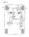
- the hybrid vehicle illustrated in FIG. 7 runs by a driving force generated by a motor MOT and/or an engine ENG, and a drive shaft of the motor MOT is directly connected to a drive shaft of the engine ENG.
- the hybrid vehicle illustrated in FIG. 8 runs by a driving force generated by a motor MOT.
- An engine ENG of the series hybrid vehicle is used only for power generation, and power generated by a generator GEN by a driving force of the engine ENG is charged in the battery 153 or supplied to the motor MOT.
- power generated by a regenerative operation of the motor MOT or the generator GEN is charged in the battery 153 via the inverter 103 and the converter 31.
- the switching operations of the converter 31 and the inverter 103 will not be performed. As a result, all the transistors of the converter 31 and the inverter 103 enter OFF states.
- the free wheel diodes are connected in parallel to the respective transistors. A cathode of each free wheel diode is connected to a collector of the associated transistor, and an anode of each free wheel diode is connected to an emitter of the associated transistor. Accordingly, when all the transistors of the converter 31 and the inverter 103 are in OFF states, regenerative power of the motor or generator is stored in the capacitor C.
- the capacitor C falls into an excessively charged state, a component of the converter 31 or the inverter 103 might be broken by a terminal voltage of the capacitor C in which overvoltage has occurred.
- the excessively charged state of the capacitor C may also similarly occur in the event of failure of the converter 31.
- a system relay SMR1 is turned ON and a system relay SMR2 is turned OFF.
- power stored in a capacitor C2 is returned to a battery B via the system relay SMR1 and a limiting resistor 11.
- the system relays SMR1 and SMR3 are turned OFF, and residual charges in the capacitor C2 are discharged through a discharge resistor 18.
- Patent Document 1 JP-2005-143259-A
- the load drive apparatus 100 of Patent Document 1 requires the system relays SMR1 to SMR3, the limiting resistor 11 and the discharge resistor 18 in order to reduce the voltages of the ends of the capacitor C2 and to discharge the residual charges. Consequently, the number of components is increased, and the resulting circuit is complicated. Furthermore, the increase in the number of components causes an increase in cost, which also results in an increase in size of the apparatus. Thus, the increase in the number of components is undesirable.
- An object of the present invention is to provide a load drive apparatus that allows power, generated by a regenerative operation of a rotary inductive load, to be stored in a battery in a simple configuration even in the event of failure of a controller or a converter.
- Claim 1 provides a load drive apparatus, including:
- Claim 2 provides the load drive apparatus, further including:
- Claim 3 provides the load drive apparatus
- regenerative power of the rotary inductive load can be charged in the battery when the battery is not fully charged, and the regenerative power can be consumed by the resistor when the battery is fully charged.
- the regenerative power can be charged or consumed in accordance with the storage capacity of the battery without being stored in the capacitor.
- FIG. 1 illustrates a system including a load drive apparatus according to a first embodiment.
- the load drive apparatus according to the first embodiment serves as an apparatus for controlling an operation of a rotary inductive load (load) 151 which is operated as a motor at the time of power running driving and operated as a generator at the time of regenerative operation.
- load rotary inductive load
- the load drive apparatus includes: a boost converter (converter) 101; a smoothing capacitor (capacitor) C; an inverter 103; and a controller 105.
- the converter 101, the capacitor C and the inverter 103 are provided between the load 151 and a battery 153 for outputting a DC high voltage (e.g., 100 V to 200 V).
- the smoothing capacitor C is provided in parallel between the converter 101 and the inverter 103.
- the system illustrated in FIG. 1 is installed on a so-called "parallel hybrid vehicle" illustrated in FIG. 7 , for example.
- a drive shaft of a motor MOT is connected to wheels Wr and Wl via no clutch.
- the converter 101 has: two-stage upper and lower transistors Tru and Trl connected in series; free wheel diodes Du and Dl connected in parallel to the upper and lower transistors, respectively; and a reactor L provided for the battery 153 (primary side).
- the converter 101 performs a switching operation on the transistors, thereby boosting an output voltage of the battery 153. Further, when a regenerative operation is performed by the load 151, the converter 101 performs a switching operation on the transistors, thereby reducing an output voltage of the inverter 103.
- the lower (low side) transistor Trl is a normally-off type semiconductor element that enters an OFF state when no voltage is applied to its base.
- the upper (high side) transistor Tru is a normally-off type semiconductor element that enters an ON state when no voltage is applied to its base and enters an OFF state upon application of a voltage thereto. Accordingly, when the converter 101 performs a boosting operation, levels of voltages applied to the bases of the transistors Tru and Trl are equal to each other, and an "H" level voltage or an "L” level voltage is applied to each base in an alternating manner. As a result, the transistors Tru and Trl periodically perform inversion operations.
- the capacitor C smoothes an output voltage of the converter 101. Further, when a regenerative operation is performed by the load 151, the capacitor C smoothes the output voltage of the inverter 103.
- the inverter 103 has: two-stage upper and lower transistors connected in series and associated with respective phases; and free wheel diodes connected in parallel to the respective transistors.
- the inverter 103 converts the output voltage of the converter 101 into a three-phase (U, V and W) AC voltage by performing a switching operation on the transistors. Further, when a regenerative operation is performed by the load 151, the inverter 103 converts a three-phase AC voltage, generated by the load 151, into a DC voltage by performing a switching operation on the transistors.
- the controller 105 controls the switching operations of the respective transistors included in the converter 101 and the inverter 103.
- the upper transistor Tru of the converter 101 is a normally-on type transistor and is thus in an ON state.
- all the transistors included in the converter 101 and the inverter 103, except for the upper transistor Tru of the converter 101, are normally-off type transistors and thus enter OFF states.
- the free wheel diodes are connected in parallel to the respective transistors. A cathode of each free wheel diode is connected to a collector of the associated transistor, and an anode of each free wheel diode is connected to an emitter of the associated transistor. Accordingly, power (regenerative power) generated by a regenerative operation of the load 151 is charged in the battery 153 via the upper free wheel diodes included in the inverter 103, the upper transistor Tru of the converter 101, and the reactor L.
- the upper transistor Tru of the converter 101 enters an ON state, and the lower transistor Trl enters an OFF state. Also in this case, the regenerative power of the load 151 is charged in the battery 153 via the inverter 103, the upper transistor Tru of the converter 101, and the reactor L.
- the upper transistor Tru of the converter 101 is a normally-on type transistor, and therefore, the transistor Tru is in an ON state in the event of failure of the controller 105 or the converter 101. Accordingly, even in the event of failure of the controller 105 or the converter 101, the regenerative power of the load 151 is charged in the battery 153 via the inverter 103, the upper transistor Tru of the converter 101, and the reactor L. Thus, even in the event of failure of the controller 105 or the converter 101, a current path is formed between the load 151 and the battery 153 via the transistor Tru, thereby preventing an overcharged state of the capacitor C.
- the inverter 103 When a failure has also occurred in the inverter 103 in the event of failure of the converter 101, the inverter 103 cannot perform field weakening control on the load 151. In that case, a counter electromotive force generated in the load 151 is higher as compared with a case where the inverter 103 functions normally. Accordingly, the regenerative power of the load 151 is higher when a failure has occurred in the inverter 103. Therefore, the above-described effects of the present embodiment are further enhanced when the inverter 103 cannot perform the switching operation.
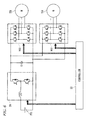
- the inverter 103 is provided in parallel for each load, and the capacitor C and the converter 101 are provided so as to be shared between the two loads.
- the system illustrated in FIG. 2 is installed on a so-called “series hybrid vehicle” illustrated in FIG. 8 or a so-called “series/parallel switching hybrid vehicle” illustrated in FIG. 9 , for example.
- a drive shaft of a motor MOT is connected to wheels Wr and Wl via no clutch.
- FIG. 3 illustrates a system including a load drive apparatus according to a second embodiment.
- the load drive apparatus according to the second embodiment further includes a current sensor 201, a voltage sensor 203 and a relay unit 205 in addition to the constituent elements of the load drive apparatus according to the first embodiment.
- a controller 207 also controls the relay unit 205 in addition to controlling the switching operations of the converter 101 and the inverter 103.
- the second embodiment is similar to the first embodiment. Accordingly, elements identical to or equivalent to those of the load drive apparatus according to the first embodiment are identified by the same reference characters or equivalent reference characters, and the description thereof will be simplified or omitted.
- the current sensor 201 detects a charge and discharge current I1 of the battery 153. A signal indicative of the charge and discharge current I1 of the battery 153, which is detected by the current sensor 201, is sent to the controller 207.
- the voltage sensor 203 detects an output voltage V1 of the battery 153. A signal indicative of the output voltage V1 of the battery 153, which is detected by the voltage sensor 203, is sent to the controller 207.
- the relay unit 205 is provided between the battery 153 and the converter 101 to open/close a power supply path between the battery 153 and the load 151.
- the relay unit 205 has: a positive-side main relay RS1; a negative-side main relay RS2; a preliminary charge relay RS3; a discharge relay RS4; a current limiting resistor R1; and a discharge resistor R2. Since a high current flows through a current supply path, the positive-side main relay RS1, the negative-side main relay RS2 and the preliminary charge relay RS3 are mechanical relays formed by mechanical contact points and coils. In FIG. 3 , illustration of the coils of the negative-side main relay RS2 and the preliminary charge relay RS3 is omitted.
- the controller 207 controls the opening/closing of the power supply path, which is performed by the relay unit 205. For example, when an ignition switch of a vehicle on which the system illustrated in FIG. 3 is installed is changed from an OFF state to an ON state, the controller 207 turns ON the negative-side main relay RS2 and the preliminary charge relay RS3 in this order. Upon turning ON of the two relays, charging of the capacitor C starts. In this case, flow of a high rush current is limited by the current limiting resistor R1. After the capacitor C has been charged, the controller 207 turns ON the positive-side main relay RS1 and turns OFF the preliminary charge relay RS3.
- the controller 207 turns OFF the positive-side main relay RS1 and the negative-side main relay RS2.
- the controller 207 derives an SOC (State Of Charge) of the battery 153 based on the charge and discharge current I1 or output voltage V1 of the battery 153.
- SOC State Of Charge
- the controller 207 adds up a charge current and a discharge current of the battery 153 for each given period of time to calculate a total charge amount and a total discharge amount, and adds or subtracts the total charge amount and total discharge amount to or from an initial SOC or an SOC obtained immediately before start of charge and discharge, thus deriving the SOC of the battery 153.
- the controller 207 derives the SOC in accordance with the output voltage V1 of the battery 153 that is being charged and discharged.
- a relationship between the output voltage V1 of the battery 153 and the SOC is obtained as a substantially linear shape within a range between a lower limit SOC and an upper limit SOC.
- the controller 207 controls the relay unit 205 in accordance with the SOC of the battery 153.
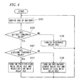
- FIG. 4 illustrates a process in the controller 207 to control the relay unit 205 in accordance with the SOC of the battery 153. As illustrated in FIG. 4 , the controller 207 derives the SOC of the battery 153 (Step S101).
- the controller 207 makes a comparison between the SOC of the battery 153 and a first threshold value, e.g., 80% (Step S103), and the processing proceeds to Step S105 when the SOC exceeds the first threshold value and proceeds to Step S107 when the SOC is equal to or lower than the first threshold value.
- a first threshold value e.g., 80%
- Step S 105 the controller 207 turns ON the discharge relay RS4 of the relay unit 205, and turns OFF the other relays.
- Step S107 the controller 207 makes a comparison between the SOC of the battery 153 and a second threshold value (e.g., 60%) which is lower than the first threshold value, and the processing proceeds to Step S109 when the SOC exceeds the second threshold value and proceeds to Step S111 when the SOC is equal to or lower than the second threshold value.
- Step S109 the controller 207 turns ON the preliminary charge relay RS3 and the negative-side main relay RS2 of the relay unit 205, and turns OFF the other relays.
- Step S111 the controller 207 turns ON the positive-side main relay RS1 and the negative-side main relay RS2 of the relay unit 205, and turns OFF the other relays.
- Step S105 i.e., when the SOC of the battery 153 is higher than the first threshold value, the discharge relay RS4 is turned ON and the other relays are turned OFF; hence, the constituent elements of the converter 101 and the subsequent constituent elements, which are located adjacent to the load 151, will be electrically disconnected from the battery 153.
- the regenerative power of the load 151 is stored in the capacitor C, but the power stored in the capacitor C is consumed by the discharge resistor R2.
- Step S109 i.e., when the SOC of the battery 153 is higher than the second threshold value but is equal to or lower than the first threshold value, the preliminary charge relay RS3 and the negative-side main relay RS2 are turned ON, and the other relays are turned OFF. In this case, the regenerative power of the load 151 is partially consumed by the resistor R1, but the remaining power is charged in the battery 153.
- Step S111 when the processing proceeds to Step S111, i.e., when the SOC of the battery 153 is equal to or lower than the second threshold value, the positive-side main relay RS1 and the negative-side main relay RS2 are turned ON, and the other relays are turned OFF. In this case, the regenerative power of the load 151 is charged in the battery 153.
- the regenerative power of the load 151 is at least partially charged in the battery 153 without disconnecting the converter 101 or the inverter 103 from the battery 153 when the battery 153 is not fully charged. Specifically, when the battery 153 is fully charged, the regenerative power of the load 151 is consumed by the discharge resistor R2. Thus, the regenerative power can be charged or consumed in accordance with the SOC of the battery.
- the converter 101 and the inverter 103 include bipolar transistors, but may alternatively include switching elements such as FETs or IGBTs.
Landscapes
- Engineering & Computer Science (AREA)
- Power Engineering (AREA)
- Transportation (AREA)
- Mechanical Engineering (AREA)
- Life Sciences & Earth Sciences (AREA)
- Sustainable Development (AREA)
- Sustainable Energy (AREA)
- Chemical & Material Sciences (AREA)
- Combustion & Propulsion (AREA)
- Inverter Devices (AREA)
- Electric Propulsion And Braking For Vehicles (AREA)
- Dc-Dc Converters (AREA)
Abstract
Description
- The present invention relates to load drive apparatuses for driving rotary inductive loads by supply of power from batteries.
-
FIG. 5 illustrates an exemplary system for driving a motor. In the system, a boost converter (converter) 31 and aninverter 103 are provided between abattery 153 for outputting a DC high voltage (e.g., 100 V to 200 V) and a rotaryinductive load 151 such as a motor or a generator. A smoothing capacitor C is provided in parallel between theconverter 31 and theinverter 103. - The
converter 31 and theinverter 103 each have transistors serving as normally-off elements. Free wheel diodes are connected in parallel to the respective transistors. Theconverter 31 performs a switching operation for alternately turning ON/OFF the upper and lower transistors, thereby boosting an output voltage of thebattery 153. Further, theinverter 103 converts an output voltage of theconverter 31 into a three-phase (U, V and W) AC voltage by performing a switching operation on the transistors. Acontroller 33 controls the switching operations performed on the respective transistors included in theconverter 31 and theinverter 103. When two loads such as a motor and a generator are provided as illustrated inFIG. 6 , theinverter 103 is provided in parallel for each of the loads. - The system illustrated in
FIG. 5 is installed on a so-called "parallel hybrid vehicle" illustrated inFIG. 7 , for example. On the other hand, the system illustrated inFIG. 6 is installed on a so-called "series hybrid vehicle" illustrated inFIG. 8 or a so-called "series/parallel switching hybrid vehicle" illustrated inFIG. 9 , for example. The hybrid vehicle illustrated inFIG. 7 runs by a driving force generated by a motor MOT and/or an engine ENG, and a drive shaft of the motor MOT is directly connected to a drive shaft of the engine ENG. On the other hand, the hybrid vehicle illustrated inFIG. 8 runs by a driving force generated by a motor MOT. An engine ENG of the series hybrid vehicle is used only for power generation, and power generated by a generator GEN by a driving force of the engine ENG is charged in thebattery 153 or supplied to the motor MOT. In each of these hybrid vehicles, power generated by a regenerative operation of the motor MOT or the generator GEN is charged in thebattery 153 via theinverter 103 and theconverter 31. - In the event of failure of the
controller 33 installed on the hybrid vehicle, the switching operations of theconverter 31 and theinverter 103 will not be performed. As a result, all the transistors of theconverter 31 and theinverter 103 enter OFF states. As mentioned above, the free wheel diodes are connected in parallel to the respective transistors. A cathode of each free wheel diode is connected to a collector of the associated transistor, and an anode of each free wheel diode is connected to an emitter of the associated transistor. Accordingly, when all the transistors of theconverter 31 and theinverter 103 are in OFF states, regenerative power of the motor or generator is stored in the capacitor C. However, when the capacitor C falls into an excessively charged state, a component of theconverter 31 or theinverter 103 might be broken by a terminal voltage of the capacitor C in which overvoltage has occurred. The excessively charged state of the capacitor C may also similarly occur in the event of failure of theconverter 31. - In a
load drive apparatus 100 ofPatent Document 1, as illustrated inFIG. 10 , upon occurrence of an abnormal condition in aboost converter 12 or aninverter 14, a system relay SMR1 is turned ON and a system relay SMR2 is turned OFF. As a result, power stored in a capacitor C2 is returned to a battery B via the system relay SMR1 and a limitingresistor 11. Then, when voltages of ends of the capacitor C2 are each reduced to a battery voltage, the system relays SMR1 and SMR3 are turned OFF, and residual charges in the capacitor C2 are discharged through adischarge resistor 18. - Patent Document 1:
JP-2005-143259-A - However, the
load drive apparatus 100 ofPatent Document 1 requires the system relays SMR1 to SMR3, the limitingresistor 11 and thedischarge resistor 18 in order to reduce the voltages of the ends of the capacitor C2 and to discharge the residual charges. Consequently, the number of components is increased, and the resulting circuit is complicated. Furthermore, the increase in the number of components causes an increase in cost, which also results in an increase in size of the apparatus. Thus, the increase in the number of components is undesirable. - An object of the present invention is to provide a load drive apparatus that allows power, generated by a regenerative operation of a rotary inductive load, to be stored in a battery in a simple configuration even in the event of failure of a controller or a converter.
-
Claim 1 provides a load drive apparatus, including: - a converter (e.g., a
boost converter 101 in embodiment) which has two switching elements (e.g., transistors Tru and Trl in embodiment) connected in series and through which a DC voltage, outputted from a battery (e.g., abattery 153 in embodiment), is converted into a DC voltage of a different level; - an inverter (e.g., an
inverter 103 in embodiment) through which the DC voltage, outputted from the converter, is converted into an AC voltage and the AC voltage is applied to a rotary inductive load (e.g., a rotaryinductive load 151 in embodiment); and - a capacitor (e.g., a smoothing capacitor C in embodiment) provided between the converter and the inverter so as to be in parallel to the converter and the inverter,
- Claim 2 provides the load drive apparatus, further including:
- a switch section (e.g., a
relay unit 205 in embodiment) having- a first path opening/closing unit (e.g., a positive-side main relay RS1, a negative-side main relay RS2 and a preliminary charge relay RS3 in embodiment) for opening/closing the power supply path,
- a second path opening/closing unit (e.g., a discharge relay RS4 in embodiment) connected in series and provided in parallel to the capacitor so as to be located closer to the rotary inductive load than the first path opening/closing unit, and
- a resistor (e.g., a discharge resistor R2 in embodiment);
- a storage capacity deriving section (e.g., a
controller 207 in embodiment) for deriving a storage capacity of the battery based on a charge and discharge current or an output voltage of the battery; and - a switch controller (e.g., the
controller 207 in embodiment) for controlling, when no switching operation is performed on the two switching elements of the converter, the switch section- so as to open the first path opening/closing unit and close the second path opening/closing unit when the storage capacity of the battery is higher than a threshold value, and
- so as to close the first path opening/closing unit and open the second path opening/closing unit when the storage capacity of the battery is equal to or lower than the threshold value.
-
Claim 3 provides the load drive apparatus, - wherein the rotary inductive load is used as a driving source for a vehicle and is connected to a wheel of the vehicle via a power transmission path through which connection/disconnection for power transmission between the rotary inductive load and the wheel cannot be performed.
- According to
Claims 1 to 3, no switching operation is performed on the two switching elements of the converter in the event of failure of the converter or the controller for controlling operations of the converter and the inverter. In this case, one of the two switching elements of the converter, which constitutes part of a current path extending from the battery to the rotary inductive load, is a normally-on type switching element and is thus in an ON state. Accordingly, power generated by a regenerative operation of the rotary inductive load can be charged in the battery via theinverter 103 and the normally-on type switching element. - According to Claims 2 to 3, in the event of failure of the converter or the controller for controlling operations of the converter and the inverter, regenerative power of the rotary inductive load can be charged in the battery when the battery is not fully charged, and the regenerative power can be consumed by the resistor when the battery is fully charged. Thus, the regenerative power can be charged or consumed in accordance with the storage capacity of the battery without being stored in the capacitor.
-
-
FIG. 1 illustrates a system including a load drive apparatus according to a first embodiment. -
FIG. 2 illustrates a system including a load drive apparatus according to another embodiment. -
FIG. 3 illustrates a system including a load drive apparatus according to a second embodiment. -
FIG. 4 illustrates a process in acontroller 207 to control arelay unit 205 in accordance with an SOC of abattery 153. -
FIG. 5 illustrates an exemplary system for driving a motor. -
FIG. 6 illustrates another exemplary system for driving a motor. -
FIG. 7 illustrates a hybrid vehicle on which the system ofFIG. 5 is installed. -
FIG. 8 illustrates a hybrid vehicle on which the system ofFIG. 6 is installed. -
FIG. 9 illustrates a hybrid vehicle on which the system ofFIG. 6 is installed. -
FIG. 10 illustrates a load drive apparatus ofPatent Document 1. - Embodiments will be described with reference to the drawings.
-
FIG. 1 illustrates a system including a load drive apparatus according to a first embodiment. InFIG. 1 , elements identical to or equivalent to those included in the system illustrated inFIG. 5 are identified by the same reference characters or equivalent reference characters. The load drive apparatus according to the first embodiment serves as an apparatus for controlling an operation of a rotary inductive load (load) 151 which is operated as a motor at the time of power running driving and operated as a generator at the time of regenerative operation. - As illustrated in
FIG. 1 , the load drive apparatus according to the first embodiment includes: a boost converter (converter) 101; a smoothing capacitor (capacitor) C; aninverter 103; and acontroller 105. Theconverter 101, the capacitor C and theinverter 103 are provided between theload 151 and abattery 153 for outputting a DC high voltage (e.g., 100 V to 200 V). The smoothing capacitor C is provided in parallel between theconverter 101 and theinverter 103. Similarly to the system ofFIG. 5 , the system illustrated inFIG. 1 is installed on a so-called "parallel hybrid vehicle" illustrated inFIG. 7 , for example. In the hybrid vehicle, a drive shaft of a motor MOT is connected to wheels Wr and Wl via no clutch. - The
converter 101 has: two-stage upper and lower transistors Tru and Trl connected in series; free wheel diodes Du and Dl connected in parallel to the upper and lower transistors, respectively; and a reactor L provided for the battery 153 (primary side). Theconverter 101 performs a switching operation on the transistors, thereby boosting an output voltage of thebattery 153. Further, when a regenerative operation is performed by theload 151, theconverter 101 performs a switching operation on the transistors, thereby reducing an output voltage of theinverter 103. - In the present embodiment, the lower (low side) transistor Trl is a normally-off type semiconductor element that enters an OFF state when no voltage is applied to its base. On the other hand, the upper (high side) transistor Tru is a normally-off type semiconductor element that enters an ON state when no voltage is applied to its base and enters an OFF state upon application of a voltage thereto. Accordingly, when the
converter 101 performs a boosting operation, levels of voltages applied to the bases of the transistors Tru and Trl are equal to each other, and an "H" level voltage or an "L" level voltage is applied to each base in an alternating manner. As a result, the transistors Tru and Trl periodically perform inversion operations. - The capacitor C smoothes an output voltage of the
converter 101. Further, when a regenerative operation is performed by theload 151, the capacitor C smoothes the output voltage of theinverter 103. - The
inverter 103 has: two-stage upper and lower transistors connected in series and associated with respective phases; and free wheel diodes connected in parallel to the respective transistors. Theinverter 103 converts the output voltage of theconverter 101 into a three-phase (U, V and W) AC voltage by performing a switching operation on the transistors. Further, when a regenerative operation is performed by theload 151, theinverter 103 converts a three-phase AC voltage, generated by theload 151, into a DC voltage by performing a switching operation on the transistors. - The
controller 105 controls the switching operations of the respective transistors included in theconverter 101 and theinverter 103. - In the event of failure of the
controller 105 of the above-described load drive apparatus, the switching operations of theconverter 101 and theinverter 103 will not be performed. In this case, the upper transistor Tru of theconverter 101 is a normally-on type transistor and is thus in an ON state. On the other hand, all the transistors included in theconverter 101 and theinverter 103, except for the upper transistor Tru of theconverter 101, are normally-off type transistors and thus enter OFF states. As mentioned above, the free wheel diodes are connected in parallel to the respective transistors. A cathode of each free wheel diode is connected to a collector of the associated transistor, and an anode of each free wheel diode is connected to an emitter of the associated transistor. Accordingly, power (regenerative power) generated by a regenerative operation of theload 151 is charged in thebattery 153 via the upper free wheel diodes included in theinverter 103, the upper transistor Tru of theconverter 101, and the reactor L. - In the event of failure of the
converter 101, the upper transistor Tru of theconverter 101 enters an ON state, and the lower transistor Trl enters an OFF state. Also in this case, the regenerative power of theload 151 is charged in thebattery 153 via theinverter 103, the upper transistor Tru of theconverter 101, and the reactor L. - In the present embodiment, the upper transistor Tru of the
converter 101 is a normally-on type transistor, and therefore, the transistor Tru is in an ON state in the event of failure of thecontroller 105 or theconverter 101. Accordingly, even in the event of failure of thecontroller 105 or theconverter 101, the regenerative power of theload 151 is charged in thebattery 153 via theinverter 103, the upper transistor Tru of theconverter 101, and the reactor L. Thus, even in the event of failure of thecontroller 105 or theconverter 101, a current path is formed between theload 151 and thebattery 153 via the transistor Tru, thereby preventing an overcharged state of the capacitor C. - When a failure has also occurred in the
inverter 103 in the event of failure of theconverter 101, theinverter 103 cannot perform field weakening control on theload 151. In that case, a counter electromotive force generated in theload 151 is higher as compared with a case where theinverter 103 functions normally. Accordingly, the regenerative power of theload 151 is higher when a failure has occurred in theinverter 103. Therefore, the above-described effects of the present embodiment are further enhanced when theinverter 103 cannot perform the switching operation. - When two loads such as a motor M and a generator G are provided as illustrated in
FIG. 2 , theinverter 103 is provided in parallel for each load, and the capacitor C and theconverter 101 are provided so as to be shared between the two loads. Similarly to the system ofFIG. 6 , the system illustrated inFIG. 2 is installed on a so-called "series hybrid vehicle" illustrated inFIG. 8 or a so-called "series/parallel switching hybrid vehicle" illustrated inFIG. 9 , for example. In the hybrid vehicle, a drive shaft of a motor MOT is connected to wheels Wr and Wl via no clutch. -
FIG. 3 illustrates a system including a load drive apparatus according to a second embodiment. As illustrated inFIG. 3 , the load drive apparatus according to the second embodiment further includes acurrent sensor 201, avoltage sensor 203 and arelay unit 205 in addition to the constituent elements of the load drive apparatus according to the first embodiment. Furthermore, acontroller 207 also controls therelay unit 205 in addition to controlling the switching operations of theconverter 101 and theinverter 103. Other than these points, the second embodiment is similar to the first embodiment. Accordingly, elements identical to or equivalent to those of the load drive apparatus according to the first embodiment are identified by the same reference characters or equivalent reference characters, and the description thereof will be simplified or omitted. - The
current sensor 201 detects a charge and discharge current I1 of thebattery 153. A signal indicative of the charge and discharge current I1 of thebattery 153, which is detected by thecurrent sensor 201, is sent to thecontroller 207. Thevoltage sensor 203 detects an output voltage V1 of thebattery 153. A signal indicative of the output voltage V1 of thebattery 153, which is detected by thevoltage sensor 203, is sent to thecontroller 207. - The
relay unit 205 is provided between thebattery 153 and theconverter 101 to open/close a power supply path between thebattery 153 and theload 151. As illustrated inFIG. 3 , therelay unit 205 has: a positive-side main relay RS1; a negative-side main relay RS2; a preliminary charge relay RS3; a discharge relay RS4; a current limiting resistor R1; and a discharge resistor R2. Since a high current flows through a current supply path, the positive-side main relay RS1, the negative-side main relay RS2 and the preliminary charge relay RS3 are mechanical relays formed by mechanical contact points and coils. InFIG. 3 , illustration of the coils of the negative-side main relay RS2 and the preliminary charge relay RS3 is omitted. - The
controller 207 controls the opening/closing of the power supply path, which is performed by therelay unit 205. For example, when an ignition switch of a vehicle on which the system illustrated inFIG. 3 is installed is changed from an OFF state to an ON state, thecontroller 207 turns ON the negative-side main relay RS2 and the preliminary charge relay RS3 in this order. Upon turning ON of the two relays, charging of the capacitor C starts. In this case, flow of a high rush current is limited by the current limiting resistor R1. After the capacitor C has been charged, thecontroller 207 turns ON the positive-side main relay RS1 and turns OFF the preliminary charge relay RS3. On the other hand, when the ignition switch of the vehicle is changed from the ON state to the OFF state or in the event of failure of theconverter 101 or theinverter 103, thecontroller 207 turns OFF the positive-side main relay RS1 and the negative-side main relay RS2. - The
controller 207 derives an SOC (State Of Charge) of thebattery 153 based on the charge and discharge current I1 or output voltage V1 of thebattery 153. When the SOC is derived based on the charge and discharge current I1 of thebattery 153, thecontroller 207 adds up a charge current and a discharge current of thebattery 153 for each given period of time to calculate a total charge amount and a total discharge amount, and adds or subtracts the total charge amount and total discharge amount to or from an initial SOC or an SOC obtained immediately before start of charge and discharge, thus deriving the SOC of thebattery 153. On the other hand, when the SOC is derived based on the output voltage V1 of thebattery 153, thecontroller 207 derives the SOC in accordance with the output voltage V1 of thebattery 153 that is being charged and discharged. A relationship between the output voltage V1 of thebattery 153 and the SOC is obtained as a substantially linear shape within a range between a lower limit SOC and an upper limit SOC. - When a regenerative operation is performed by the
load 151 in the event of failure of theconverter 101 or theinverter 103, thecontroller 207 controls therelay unit 205 in accordance with the SOC of thebattery 153.FIG. 4 illustrates a process in thecontroller 207 to control therelay unit 205 in accordance with the SOC of thebattery 153. As illustrated inFIG. 4 , thecontroller 207 derives the SOC of the battery 153 (Step S101). Subsequently, thecontroller 207 makes a comparison between the SOC of thebattery 153 and a first threshold value, e.g., 80% (Step S103), and the processing proceeds to Step S105 when the SOC exceeds the first threshold value and proceeds to Step S107 when the SOC is equal to or lower than the first threshold value. - In
Step S 105, thecontroller 207 turns ON the discharge relay RS4 of therelay unit 205, and turns OFF the other relays. On the other hand, in Step S107, thecontroller 207 makes a comparison between the SOC of thebattery 153 and a second threshold value (e.g., 60%) which is lower than the first threshold value, and the processing proceeds to Step S109 when the SOC exceeds the second threshold value and proceeds to Step S111 when the SOC is equal to or lower than the second threshold value. In Step S109, thecontroller 207 turns ON the preliminary charge relay RS3 and the negative-side main relay RS2 of therelay unit 205, and turns OFF the other relays. On the other hand, in Step S111, thecontroller 207 turns ON the positive-side main relay RS1 and the negative-side main relay RS2 of therelay unit 205, and turns OFF the other relays. - When the processing proceeds to Step S105, i.e., when the SOC of the
battery 153 is higher than the first threshold value, the discharge relay RS4 is turned ON and the other relays are turned OFF; hence, the constituent elements of theconverter 101 and the subsequent constituent elements, which are located adjacent to theload 151, will be electrically disconnected from thebattery 153. In this case, the regenerative power of theload 151 is stored in the capacitor C, but the power stored in the capacitor C is consumed by the discharge resistor R2. - Further, when the processing proceeds to Step S109, i.e., when the SOC of the
battery 153 is higher than the second threshold value but is equal to or lower than the first threshold value, the preliminary charge relay RS3 and the negative-side main relay RS2 are turned ON, and the other relays are turned OFF. In this case, the regenerative power of theload 151 is partially consumed by the resistor R1, but the remaining power is charged in thebattery 153. On the other hand, when the processing proceeds to Step S111, i.e., when the SOC of thebattery 153 is equal to or lower than the second threshold value, the positive-side main relay RS1 and the negative-side main relay RS2 are turned ON, and the other relays are turned OFF. In this case, the regenerative power of theload 151 is charged in thebattery 153. - In the present embodiment, even in the event of failure of the
converter 101 or theinverter 103, the regenerative power of theload 151 is at least partially charged in thebattery 153 without disconnecting theconverter 101 or theinverter 103 from thebattery 153 when thebattery 153 is not fully charged. Specifically, when thebattery 153 is fully charged, the regenerative power of theload 151 is consumed by the discharge resistor R2. Thus, the regenerative power can be charged or consumed in accordance with the SOC of the battery. - In the embodiments, the
converter 101 and theinverter 103 include bipolar transistors, but may alternatively include switching elements such as FETs or IGBTs. - Although the present invention has been described with reference to the above-mentioned embodiments, various changes and modifications may be made to the embodiments without departing from the spirit and scope of the present invention.
- The present application is based on Japanese Patent Application No.
2010-045873 -
- 101
- boost converter (converter)
- 103
- inverter
- 105, 207
- controller
- 151
- rotary inductive load
- 153
- battery
- 201
- current sensor
- 203
- voltage sensor
- 205
- relay unit
- C
- smoothing capacitor (capacitor)
- Du, Dl
- free wheel diode
- L
- reactor
- Tru, Trl
- transistor
- RS1
- positive-side main relay
- RS2
- negative-side main relay
- RS3
- preliminary charge relay
- RS4
- discharge relay
- R1
- current limiting resistor
- R2
- discharge resistor
Claims (3)
- A load drive apparatus, including:a converter which has two switching elements connected in series and through which a DC voltage, outputted from a battery, is converted into a DC voltage of a different level;an inverter through which the DC voltage, outputted from the converter, is converted into an AC voltage and the AC voltage is applied to a rotary inductive load; anda capacitor provided between the converter and the inverter so as to be in parallel to the converter and the inverter,wherein one of the two switching elements, which constitutes part of a power supply path extending from the battery to the rotary inductive load, is a normally-on type semiconductor element.
- The apparatus of Claim 1, further including:a switch section having
a first path opening/closing unit for opening/closing the power supply path,
a second path opening/closing unit connected in series and provided in parallel to the capacitor so as to be located closer to the rotary inductive load than the first path opening/closing unit, and
a resistor;a storage capacity deriving section for deriving a storage capacity of the battery based on a charge and discharge current or an output voltage of the battery; anda switch controller for controlling, when no switching operation is performed on the two switching elements of the converter, the switch section
so as to open the first path opening/closing unit and close the second path opening/closing unit when the storage capacity of the battery is higher than a threshold value, and
so as to close the first path opening/closing unit and open the second path opening/closing unit when the storage capacity of the battery is equal to or lower than the threshold value. - The apparatus of Claim 1 or 2,
wherein the rotary inductive load is used as a driving source for a vehicle and is connected to a wheel of the vehicle via a power transmission path through which connection/disconnection for power transmission between the rotary inductive load and the wheel cannot be performed.
Applications Claiming Priority (2)
| Application Number | Priority Date | Filing Date | Title |
|---|---|---|---|
| JP2010045873 | 2010-03-02 | ||
| PCT/JP2011/054547 WO2011108501A1 (en) | 2010-03-02 | 2011-02-28 | Load driving device |
Publications (2)
| Publication Number | Publication Date |
|---|---|
| EP2544346A1 true EP2544346A1 (en) | 2013-01-09 |
| EP2544346A4 EP2544346A4 (en) | 2013-12-04 |
Family
ID=44542153
Family Applications (1)
| Application Number | Title | Priority Date | Filing Date |
|---|---|---|---|
| EP11750611.3A Withdrawn EP2544346A4 (en) | 2010-03-02 | 2011-02-28 | Load driving device |
Country Status (5)
| Country | Link |
|---|---|
| US (1) | US20130020972A1 (en) |
| EP (1) | EP2544346A4 (en) |
| JP (1) | JP5557898B2 (en) |
| CN (1) | CN102712256A (en) |
| WO (1) | WO2011108501A1 (en) |
Cited By (1)
| Publication number | Priority date | Publication date | Assignee | Title |
|---|---|---|---|---|
| WO2017198913A1 (en) * | 2016-05-20 | 2017-11-23 | Renault S.A.S | Method for controlling the torque available on a hybrid vehicle while changing gears |
Families Citing this family (7)
| Publication number | Priority date | Publication date | Assignee | Title |
|---|---|---|---|---|
| CN105246751B (en) * | 2013-05-29 | 2017-05-10 | 日产自动车株式会社 | Control devices for plug-in hybrid vehicles |
| GB201317749D0 (en) | 2013-10-08 | 2013-11-20 | Dyson Technology Ltd | AC/DC boost converter |
| EP3553914B1 (en) * | 2013-11-13 | 2020-10-07 | Volvo Lastvagnar Aktiebolag | Charge/discharge system |
| JPWO2016063887A1 (en) * | 2014-10-21 | 2017-09-07 | ナブテスコ株式会社 | AC motor drive device |
| JP2017022872A (en) * | 2015-07-10 | 2017-01-26 | トヨタ自動車株式会社 | Power supply system |
| JP6296310B2 (en) * | 2016-11-25 | 2018-03-20 | 国立大学法人長岡技術科学大学 | AC electric machine system and control method thereof |
| US11075574B1 (en) * | 2020-12-29 | 2021-07-27 | Altec Industries, Inc. | Non-conductive shaft generator |
Family Cites Families (14)
| Publication number | Priority date | Publication date | Assignee | Title |
|---|---|---|---|---|
| US4663547A (en) * | 1981-04-24 | 1987-05-05 | General Electric Company | Composite circuit for power semiconductor switching |
| JP3505826B2 (en) * | 1994-11-29 | 2004-03-15 | 日産自動車株式会社 | Regenerative braking device for electric vehicles |
| JPH10164709A (en) * | 1996-11-27 | 1998-06-19 | Isuzu Motors Ltd | Power supply and power supply for electric vehicle |
| JPH1118464A (en) * | 1997-06-23 | 1999-01-22 | Sanyo Denki Co Ltd | Motor control device |
| JP2004357412A (en) * | 2003-05-29 | 2004-12-16 | Nissan Motor Co Ltd | Dc power supply device for inverter |
| US7245175B2 (en) * | 2003-06-30 | 2007-07-17 | Sanken Electric Co. Ltd. | Semiconductor switch |
| JP4432463B2 (en) * | 2003-11-10 | 2010-03-17 | トヨタ自動車株式会社 | LOAD DRIVE DEVICE AND COMPUTER-READABLE RECORDING MEDIUM RECORDING PROGRAM FOR CAUSING COMPUTER TO EXECUTE THE OPERATION |
| JP2006223032A (en) * | 2005-02-09 | 2006-08-24 | Sumitomo Electric Ind Ltd | Switching device |
| JP2006314154A (en) * | 2005-05-06 | 2006-11-16 | Sumitomo Electric Ind Ltd | Power converter |
| JP4747933B2 (en) * | 2006-04-26 | 2011-08-17 | トヨタ自動車株式会社 | Power supply device and vehicle equipped with the same |
| DE102006029928B3 (en) * | 2006-06-29 | 2007-09-06 | Siemens Ag | Electronic switching device for switching high electric current, has isolating unit connected between control connection of switching unit and load supply of another switching unit, where isolation unit decouples switching units |
| JP4946508B2 (en) * | 2007-02-28 | 2012-06-06 | 株式会社日立製作所 | Semiconductor circuit |
| US8339817B2 (en) * | 2008-02-04 | 2012-12-25 | Nxp B.V. | Method of operating a resonant power converter and a controller therefor |
| WO2010137127A1 (en) * | 2009-05-27 | 2010-12-02 | トヨタ自動車株式会社 | Control device for a voltage converter and vehicles equipped with same, and a voltage converter control method |
-
2011
- 2011-02-28 US US13/582,322 patent/US20130020972A1/en not_active Abandoned
- 2011-02-28 CN CN2011800062144A patent/CN102712256A/en active Pending
- 2011-02-28 JP JP2012503136A patent/JP5557898B2/en not_active Expired - Fee Related
- 2011-02-28 EP EP11750611.3A patent/EP2544346A4/en not_active Withdrawn
- 2011-02-28 WO PCT/JP2011/054547 patent/WO2011108501A1/en not_active Ceased
Cited By (3)
| Publication number | Priority date | Publication date | Assignee | Title |
|---|---|---|---|---|
| WO2017198913A1 (en) * | 2016-05-20 | 2017-11-23 | Renault S.A.S | Method for controlling the torque available on a hybrid vehicle while changing gears |
| FR3051419A1 (en) * | 2016-05-20 | 2017-11-24 | Renault Sas | TORQUE CONTROL METHOD AVAILABLE ON A HYBRID VEHICLE DURING SPEEDS |
| EP3458293A1 (en) * | 2016-05-20 | 2019-03-27 | Renault S.A.S. | Method for controlling the torque available on a hybrid vehicle while changing gears |
Also Published As
| Publication number | Publication date |
|---|---|
| JP5557898B2 (en) | 2014-07-23 |
| US20130020972A1 (en) | 2013-01-24 |
| EP2544346A4 (en) | 2013-12-04 |
| CN102712256A (en) | 2012-10-03 |
| JPWO2011108501A1 (en) | 2013-06-27 |
| WO2011108501A1 (en) | 2011-09-09 |
Similar Documents
| Publication | Publication Date | Title |
|---|---|---|
| CN109428473B (en) | vehicle power system | |
| CN111688492B (en) | Power supply system | |
| US10787136B2 (en) | Electric power system for controlling pre-charge of vehicle | |
| US8901882B2 (en) | System of recharging battery of hybrid vehicle using diodes connected between inverter and neutral points of two motors, and commercial electricity applied to the neutral points | |
| EP2544346A1 (en) | Load driving device | |
| US7269535B2 (en) | Fault diagnosing apparatus for vehicle and fault diagnosing method for vehicle | |
| US8487558B2 (en) | Electric vehicle | |
| KR101171908B1 (en) | System of dc link pre-recharge for plug-in hybrid vehicle | |
| CN104487280B (en) | The control method of vehicle, power-supply system and power-supply system | |
| US20140049215A1 (en) | Method for monitoring the charging mode of an energy store in a vechile and charging system for charging an energy store in a vechile | |
| RU2696539C2 (en) | Onboard network for vehicle | |
| US10046646B2 (en) | Power conversion system for electric vehicles | |
| US20130015802A1 (en) | Method for discharging charges remaining in capacitor in drive apparatus | |
| CN103444065B (en) | The power-supply system of vehicle | |
| US20170361713A1 (en) | Power conversion system | |
| US10525838B2 (en) | Power conversion system | |
| US9774215B2 (en) | Power conversion apparatus | |
| CN115003541B (en) | Power supply system | |
| CN115158015B (en) | Power conversion device and electric vehicle | |
| CN107710589A (en) | Low pressure discharge and drive and control circuit for the traction convertor of vehicle | |
| JP5949436B2 (en) | Vehicle, power supply system, and control method for power supply system | |
| JP2018107987A (en) | Railway vehicle circuit system | |
| JP2013150525A (en) | Electric car | |
| CN111204220B (en) | Electric automobile | |
| US11012021B2 (en) | Inverter device and control circuit therefor, and motor driving system |
Legal Events
| Date | Code | Title | Description |
|---|---|---|---|
| PUAI | Public reference made under article 153(3) epc to a published international application that has entered the european phase |
Free format text: ORIGINAL CODE: 0009012 |
|
| 17P | Request for examination filed |
Effective date: 20120831 |
|
| AK | Designated contracting states |
Kind code of ref document: A1 Designated state(s): AL AT BE BG CH CY CZ DE DK EE ES FI FR GB GR HR HU IE IS IT LI LT LU LV MC MK MT NL NO PL PT RO RS SE SI SK SM TR |
|
| DAX | Request for extension of the european patent (deleted) | ||
| A4 | Supplementary search report drawn up and despatched |
Effective date: 20131105 |
|
| RIC1 | Information provided on ipc code assigned before grant |
Ipc: B60K 6/442 20071001ALI20131029BHEP Ipc: B60L 15/20 20060101ALI20131029BHEP Ipc: H02M 3/155 20060101AFI20131029BHEP Ipc: B60L 11/12 20060101ALI20131029BHEP Ipc: B60K 6/22 20071001ALI20131029BHEP Ipc: B60L 11/14 20060101ALI20131029BHEP Ipc: H02M 7/48 20070101ALI20131029BHEP Ipc: B60K 6/46 20071001ALI20131029BHEP Ipc: B60L 11/00 20060101ALI20131029BHEP Ipc: B60L 7/14 20060101ALI20131029BHEP Ipc: B60L 7/18 20060101ALI20131029BHEP Ipc: H02J 7/34 20060101ALI20131029BHEP Ipc: B60L 3/00 20060101ALI20131029BHEP Ipc: B60L 15/00 20060101ALI20131029BHEP Ipc: B60K 6/485 20071001ALI20131029BHEP Ipc: H02P 27/06 20060101ALI20131029BHEP |
|
| 17Q | First examination report despatched |
Effective date: 20131126 |
|
| GRAP | Despatch of communication of intention to grant a patent |
Free format text: ORIGINAL CODE: EPIDOSNIGR1 |
|
| RIC1 | Information provided on ipc code assigned before grant |
Ipc: B60K 6/485 20071001ALI20140905BHEP Ipc: B60L 11/14 20060101ALI20140905BHEP Ipc: B60K 6/442 20071001ALI20140905BHEP Ipc: H02J 7/34 20060101ALI20140905BHEP Ipc: B60L 3/00 20060101ALI20140905BHEP Ipc: B60L 7/18 20060101ALI20140905BHEP Ipc: H02M 3/155 20060101AFI20140905BHEP Ipc: B60L 15/20 20060101ALI20140905BHEP Ipc: H02M 7/48 20070101ALI20140905BHEP Ipc: B60L 11/00 20060101ALI20140905BHEP Ipc: H02P 27/06 20060101ALI20140905BHEP Ipc: B60L 11/12 20060101ALI20140905BHEP Ipc: B60K 6/46 20071001ALI20140905BHEP Ipc: B60L 7/14 20060101ALI20140905BHEP Ipc: B60K 6/22 20071001ALI20140905BHEP Ipc: B60L 15/00 20060101ALI20140905BHEP |
|
| INTG | Intention to grant announced |
Effective date: 20140922 |
|
| STAA | Information on the status of an ep patent application or granted ep patent |
Free format text: STATUS: THE APPLICATION IS DEEMED TO BE WITHDRAWN |
|
| 18D | Application deemed to be withdrawn |
Effective date: 20150203 |