EP2544325A2 - Scale-free routing topology for a power network - Google Patents
Scale-free routing topology for a power network Download PDFInfo
- Publication number
- EP2544325A2 EP2544325A2 EP12173931A EP12173931A EP2544325A2 EP 2544325 A2 EP2544325 A2 EP 2544325A2 EP 12173931 A EP12173931 A EP 12173931A EP 12173931 A EP12173931 A EP 12173931A EP 2544325 A2 EP2544325 A2 EP 2544325A2
- Authority
- EP
- European Patent Office
- Prior art keywords
- distribution devices
- power network
- distribution
- restored
- network
- Prior art date
- Legal status (The legal status is an assumption and is not a legal conclusion. Google has not performed a legal analysis and makes no representation as to the accuracy of the status listed.)
- Withdrawn
Links
Images


Classifications
-
- H—ELECTRICITY
- H02—GENERATION; CONVERSION OR DISTRIBUTION OF ELECTRIC POWER
- H02J—CIRCUIT ARRANGEMENTS OR SYSTEMS FOR SUPPLYING OR DISTRIBUTING ELECTRIC POWER; SYSTEMS FOR STORING ELECTRIC ENERGY
- H02J3/00—Circuit arrangements for ac mains or ac distribution networks
- H02J3/007—Arrangements for selectively connecting the load or loads to one or several among a plurality of power lines or power sources
- H02J3/0073—Arrangements for selectively connecting the load or loads to one or several among a plurality of power lines or power sources for providing alternative feeding paths between load and source when the main path fails, e.g. transformers, busbars
-
- H—ELECTRICITY
- H02—GENERATION; CONVERSION OR DISTRIBUTION OF ELECTRIC POWER
- H02J—CIRCUIT ARRANGEMENTS OR SYSTEMS FOR SUPPLYING OR DISTRIBUTING ELECTRIC POWER; SYSTEMS FOR STORING ELECTRIC ENERGY
- H02J13/00—Circuit arrangements for providing remote indication of network conditions, e.g. an instantaneous record of the open or closed condition of each circuitbreaker in the network; Circuit arrangements for providing remote control of switching means in a power distribution network, e.g. switching in and out of current consumers by using a pulse code signal carried by the network
- H02J13/00006—Circuit arrangements for providing remote indication of network conditions, e.g. an instantaneous record of the open or closed condition of each circuitbreaker in the network; Circuit arrangements for providing remote control of switching means in a power distribution network, e.g. switching in and out of current consumers by using a pulse code signal carried by the network characterised by information or instructions transport means between the monitoring, controlling or managing units and monitored, controlled or operated power network element or electrical equipment
- H02J13/00007—Circuit arrangements for providing remote indication of network conditions, e.g. an instantaneous record of the open or closed condition of each circuitbreaker in the network; Circuit arrangements for providing remote control of switching means in a power distribution network, e.g. switching in and out of current consumers by using a pulse code signal carried by the network characterised by information or instructions transport means between the monitoring, controlling or managing units and monitored, controlled or operated power network element or electrical equipment using the power network as support for the transmission
- H02J13/00009—Circuit arrangements for providing remote indication of network conditions, e.g. an instantaneous record of the open or closed condition of each circuitbreaker in the network; Circuit arrangements for providing remote control of switching means in a power distribution network, e.g. switching in and out of current consumers by using a pulse code signal carried by the network characterised by information or instructions transport means between the monitoring, controlling or managing units and monitored, controlled or operated power network element or electrical equipment using the power network as support for the transmission using pulsed signals
-
- H—ELECTRICITY
- H02—GENERATION; CONVERSION OR DISTRIBUTION OF ELECTRIC POWER
- H02J—CIRCUIT ARRANGEMENTS OR SYSTEMS FOR SUPPLYING OR DISTRIBUTING ELECTRIC POWER; SYSTEMS FOR STORING ELECTRIC ENERGY
- H02J13/00—Circuit arrangements for providing remote indication of network conditions, e.g. an instantaneous record of the open or closed condition of each circuitbreaker in the network; Circuit arrangements for providing remote control of switching means in a power distribution network, e.g. switching in and out of current consumers by using a pulse code signal carried by the network
- H02J13/00006—Circuit arrangements for providing remote indication of network conditions, e.g. an instantaneous record of the open or closed condition of each circuitbreaker in the network; Circuit arrangements for providing remote control of switching means in a power distribution network, e.g. switching in and out of current consumers by using a pulse code signal carried by the network characterised by information or instructions transport means between the monitoring, controlling or managing units and monitored, controlled or operated power network element or electrical equipment
- H02J13/00016—Circuit arrangements for providing remote indication of network conditions, e.g. an instantaneous record of the open or closed condition of each circuitbreaker in the network; Circuit arrangements for providing remote control of switching means in a power distribution network, e.g. switching in and out of current consumers by using a pulse code signal carried by the network characterised by information or instructions transport means between the monitoring, controlling or managing units and monitored, controlled or operated power network element or electrical equipment using a wired telecommunication network or a data transmission bus
- H02J13/00018—Circuit arrangements for providing remote indication of network conditions, e.g. an instantaneous record of the open or closed condition of each circuitbreaker in the network; Circuit arrangements for providing remote control of switching means in a power distribution network, e.g. switching in and out of current consumers by using a pulse code signal carried by the network characterised by information or instructions transport means between the monitoring, controlling or managing units and monitored, controlled or operated power network element or electrical equipment using a wired telecommunication network or a data transmission bus using phone lines
-
- H—ELECTRICITY
- H02—GENERATION; CONVERSION OR DISTRIBUTION OF ELECTRIC POWER
- H02J—CIRCUIT ARRANGEMENTS OR SYSTEMS FOR SUPPLYING OR DISTRIBUTING ELECTRIC POWER; SYSTEMS FOR STORING ELECTRIC ENERGY
- H02J13/00—Circuit arrangements for providing remote indication of network conditions, e.g. an instantaneous record of the open or closed condition of each circuitbreaker in the network; Circuit arrangements for providing remote control of switching means in a power distribution network, e.g. switching in and out of current consumers by using a pulse code signal carried by the network
- H02J13/00006—Circuit arrangements for providing remote indication of network conditions, e.g. an instantaneous record of the open or closed condition of each circuitbreaker in the network; Circuit arrangements for providing remote control of switching means in a power distribution network, e.g. switching in and out of current consumers by using a pulse code signal carried by the network characterised by information or instructions transport means between the monitoring, controlling or managing units and monitored, controlled or operated power network element or electrical equipment
- H02J13/00022—Circuit arrangements for providing remote indication of network conditions, e.g. an instantaneous record of the open or closed condition of each circuitbreaker in the network; Circuit arrangements for providing remote control of switching means in a power distribution network, e.g. switching in and out of current consumers by using a pulse code signal carried by the network characterised by information or instructions transport means between the monitoring, controlling or managing units and monitored, controlled or operated power network element or electrical equipment using wireless data transmission
- H02J13/00024—Circuit arrangements for providing remote indication of network conditions, e.g. an instantaneous record of the open or closed condition of each circuitbreaker in the network; Circuit arrangements for providing remote control of switching means in a power distribution network, e.g. switching in and out of current consumers by using a pulse code signal carried by the network characterised by information or instructions transport means between the monitoring, controlling or managing units and monitored, controlled or operated power network element or electrical equipment using wireless data transmission by means of mobile telephony
-
- H—ELECTRICITY
- H02—GENERATION; CONVERSION OR DISTRIBUTION OF ELECTRIC POWER
- H02J—CIRCUIT ARRANGEMENTS OR SYSTEMS FOR SUPPLYING OR DISTRIBUTING ELECTRIC POWER; SYSTEMS FOR STORING ELECTRIC ENERGY
- H02J13/00—Circuit arrangements for providing remote indication of network conditions, e.g. an instantaneous record of the open or closed condition of each circuitbreaker in the network; Circuit arrangements for providing remote control of switching means in a power distribution network, e.g. switching in and out of current consumers by using a pulse code signal carried by the network
- H02J13/00006—Circuit arrangements for providing remote indication of network conditions, e.g. an instantaneous record of the open or closed condition of each circuitbreaker in the network; Circuit arrangements for providing remote control of switching means in a power distribution network, e.g. switching in and out of current consumers by using a pulse code signal carried by the network characterised by information or instructions transport means between the monitoring, controlling or managing units and monitored, controlled or operated power network element or electrical equipment
- H02J13/00022—Circuit arrangements for providing remote indication of network conditions, e.g. an instantaneous record of the open or closed condition of each circuitbreaker in the network; Circuit arrangements for providing remote control of switching means in a power distribution network, e.g. switching in and out of current consumers by using a pulse code signal carried by the network characterised by information or instructions transport means between the monitoring, controlling or managing units and monitored, controlled or operated power network element or electrical equipment using wireless data transmission
- H02J13/00026—Circuit arrangements for providing remote indication of network conditions, e.g. an instantaneous record of the open or closed condition of each circuitbreaker in the network; Circuit arrangements for providing remote control of switching means in a power distribution network, e.g. switching in and out of current consumers by using a pulse code signal carried by the network characterised by information or instructions transport means between the monitoring, controlling or managing units and monitored, controlled or operated power network element or electrical equipment using wireless data transmission involving a local wireless network, e.g. Wi-Fi, ZigBee or Bluetooth
-
- H—ELECTRICITY
- H02—GENERATION; CONVERSION OR DISTRIBUTION OF ELECTRIC POWER
- H02J—CIRCUIT ARRANGEMENTS OR SYSTEMS FOR SUPPLYING OR DISTRIBUTING ELECTRIC POWER; SYSTEMS FOR STORING ELECTRIC ENERGY
- H02J13/00—Circuit arrangements for providing remote indication of network conditions, e.g. an instantaneous record of the open or closed condition of each circuitbreaker in the network; Circuit arrangements for providing remote control of switching means in a power distribution network, e.g. switching in and out of current consumers by using a pulse code signal carried by the network
- H02J13/00032—Systems characterised by the controlled or operated power network elements or equipment, the power network elements or equipment not otherwise provided for
- H02J13/00034—Systems characterised by the controlled or operated power network elements or equipment, the power network elements or equipment not otherwise provided for the elements or equipment being or involving an electric power substation
-
- H—ELECTRICITY
- H04—ELECTRIC COMMUNICATION TECHNIQUE
- H04L—TRANSMISSION OF DIGITAL INFORMATION, e.g. TELEGRAPHIC COMMUNICATION
- H04L41/00—Arrangements for maintenance, administration or management of data switching networks, e.g. of packet switching networks
- H04L41/06—Management of faults, events, alarms or notifications
- H04L41/0654—Management of faults, events, alarms or notifications using network fault recovery
- H04L41/0663—Performing the actions predefined by failover planning, e.g. switching to standby network elements
-
- H—ELECTRICITY
- H04—ELECTRIC COMMUNICATION TECHNIQUE
- H04L—TRANSMISSION OF DIGITAL INFORMATION, e.g. TELEGRAPHIC COMMUNICATION
- H04L41/00—Arrangements for maintenance, administration or management of data switching networks, e.g. of packet switching networks
- H04L41/12—Discovery or management of network topologies
-
- Y—GENERAL TAGGING OF NEW TECHNOLOGICAL DEVELOPMENTS; GENERAL TAGGING OF CROSS-SECTIONAL TECHNOLOGIES SPANNING OVER SEVERAL SECTIONS OF THE IPC; TECHNICAL SUBJECTS COVERED BY FORMER USPC CROSS-REFERENCE ART COLLECTIONS [XRACs] AND DIGESTS
- Y02—TECHNOLOGIES OR APPLICATIONS FOR MITIGATION OR ADAPTATION AGAINST CLIMATE CHANGE
- Y02E—REDUCTION OF GREENHOUSE GAS [GHG] EMISSIONS, RELATED TO ENERGY GENERATION, TRANSMISSION OR DISTRIBUTION
- Y02E60/00—Enabling technologies; Technologies with a potential or indirect contribution to GHG emissions mitigation
-
- Y—GENERAL TAGGING OF NEW TECHNOLOGICAL DEVELOPMENTS; GENERAL TAGGING OF CROSS-SECTIONAL TECHNOLOGIES SPANNING OVER SEVERAL SECTIONS OF THE IPC; TECHNICAL SUBJECTS COVERED BY FORMER USPC CROSS-REFERENCE ART COLLECTIONS [XRACs] AND DIGESTS
- Y04—INFORMATION OR COMMUNICATION TECHNOLOGIES HAVING AN IMPACT ON OTHER TECHNOLOGY AREAS
- Y04S—SYSTEMS INTEGRATING TECHNOLOGIES RELATED TO POWER NETWORK OPERATION, COMMUNICATION OR INFORMATION TECHNOLOGIES FOR IMPROVING THE ELECTRICAL POWER GENERATION, TRANSMISSION, DISTRIBUTION, MANAGEMENT OR USAGE, i.e. SMART GRIDS
- Y04S10/00—Systems supporting electrical power generation, transmission or distribution
- Y04S10/50—Systems or methods supporting the power network operation or management, involving a certain degree of interaction with the load-side end user applications
- Y04S10/52—Outage or fault management, e.g. fault detection or location
-
- Y—GENERAL TAGGING OF NEW TECHNOLOGICAL DEVELOPMENTS; GENERAL TAGGING OF CROSS-SECTIONAL TECHNOLOGIES SPANNING OVER SEVERAL SECTIONS OF THE IPC; TECHNICAL SUBJECTS COVERED BY FORMER USPC CROSS-REFERENCE ART COLLECTIONS [XRACs] AND DIGESTS
- Y04—INFORMATION OR COMMUNICATION TECHNOLOGIES HAVING AN IMPACT ON OTHER TECHNOLOGY AREAS
- Y04S—SYSTEMS INTEGRATING TECHNOLOGIES RELATED TO POWER NETWORK OPERATION, COMMUNICATION OR INFORMATION TECHNOLOGIES FOR IMPROVING THE ELECTRICAL POWER GENERATION, TRANSMISSION, DISTRIBUTION, MANAGEMENT OR USAGE, i.e. SMART GRIDS
- Y04S40/00—Systems for electrical power generation, transmission, distribution or end-user application management characterised by the use of communication or information technologies, or communication or information technology specific aspects supporting them
- Y04S40/12—Systems for electrical power generation, transmission, distribution or end-user application management characterised by the use of communication or information technologies, or communication or information technology specific aspects supporting them characterised by data transport means between the monitoring, controlling or managing units and monitored, controlled or operated electrical equipment
- Y04S40/121—Systems for electrical power generation, transmission, distribution or end-user application management characterised by the use of communication or information technologies, or communication or information technology specific aspects supporting them characterised by data transport means between the monitoring, controlling or managing units and monitored, controlled or operated electrical equipment using the power network as support for the transmission
-
- Y—GENERAL TAGGING OF NEW TECHNOLOGICAL DEVELOPMENTS; GENERAL TAGGING OF CROSS-SECTIONAL TECHNOLOGIES SPANNING OVER SEVERAL SECTIONS OF THE IPC; TECHNICAL SUBJECTS COVERED BY FORMER USPC CROSS-REFERENCE ART COLLECTIONS [XRACs] AND DIGESTS
- Y04—INFORMATION OR COMMUNICATION TECHNOLOGIES HAVING AN IMPACT ON OTHER TECHNOLOGY AREAS
- Y04S—SYSTEMS INTEGRATING TECHNOLOGIES RELATED TO POWER NETWORK OPERATION, COMMUNICATION OR INFORMATION TECHNOLOGIES FOR IMPROVING THE ELECTRICAL POWER GENERATION, TRANSMISSION, DISTRIBUTION, MANAGEMENT OR USAGE, i.e. SMART GRIDS
- Y04S40/00—Systems for electrical power generation, transmission, distribution or end-user application management characterised by the use of communication or information technologies, or communication or information technology specific aspects supporting them
- Y04S40/12—Systems for electrical power generation, transmission, distribution or end-user application management characterised by the use of communication or information technologies, or communication or information technology specific aspects supporting them characterised by data transport means between the monitoring, controlling or managing units and monitored, controlled or operated electrical equipment
- Y04S40/124—Systems for electrical power generation, transmission, distribution or end-user application management characterised by the use of communication or information technologies, or communication or information technology specific aspects supporting them characterised by data transport means between the monitoring, controlling or managing units and monitored, controlled or operated electrical equipment using wired telecommunication networks or data transmission busses
-
- Y—GENERAL TAGGING OF NEW TECHNOLOGICAL DEVELOPMENTS; GENERAL TAGGING OF CROSS-SECTIONAL TECHNOLOGIES SPANNING OVER SEVERAL SECTIONS OF THE IPC; TECHNICAL SUBJECTS COVERED BY FORMER USPC CROSS-REFERENCE ART COLLECTIONS [XRACs] AND DIGESTS
- Y04—INFORMATION OR COMMUNICATION TECHNOLOGIES HAVING AN IMPACT ON OTHER TECHNOLOGY AREAS
- Y04S—SYSTEMS INTEGRATING TECHNOLOGIES RELATED TO POWER NETWORK OPERATION, COMMUNICATION OR INFORMATION TECHNOLOGIES FOR IMPROVING THE ELECTRICAL POWER GENERATION, TRANSMISSION, DISTRIBUTION, MANAGEMENT OR USAGE, i.e. SMART GRIDS
- Y04S40/00—Systems for electrical power generation, transmission, distribution or end-user application management characterised by the use of communication or information technologies, or communication or information technology specific aspects supporting them
- Y04S40/12—Systems for electrical power generation, transmission, distribution or end-user application management characterised by the use of communication or information technologies, or communication or information technology specific aspects supporting them characterised by data transport means between the monitoring, controlling or managing units and monitored, controlled or operated electrical equipment
- Y04S40/126—Systems for electrical power generation, transmission, distribution or end-user application management characterised by the use of communication or information technologies, or communication or information technology specific aspects supporting them characterised by data transport means between the monitoring, controlling or managing units and monitored, controlled or operated electrical equipment using wireless data transmission
Definitions
- a smart grid delivers electricity to consumers while leveraging digital communication and control technologies to minimize financial cost, save energy, and increase reliability. If designed properly, the smart grid will have a significant impact on improving a wide range of aspects in the electric power generation and distribution industry. Examples include self-healing, high-reliability, resistance to cyber-attack, accommodation of a wide variety of types of distributed generation and storage mechanisms, optimized asset allocation, and minimization of operation and maintenance expenses as well as high-resolution market control that incorporates advanced metering and demand-response.
- a scale free communication network in a power network includes a plurality of distribution devices communicatively coupled to each other in a power network that include a protection device and a controller coupled to each of the plurality of distribution devices in the power network.
- the controller identifies a plurality of isolated distribution devices.
- the controller further restores the plurality of isolated distribution devices in the power network by automatically activating the tie-switch in the power network.
- the controller also computes reliability indicators for each of the restored distribution device in the power network.
- the controller identifies critical distribution devices in the power network based on the computed reliability indicators and establishes a scale free communications network within the power network based on the identified critical distribution devices.
- Embodiments of the present invention include a scale free communication network.
- the scale free communication network in a power network comprises a plurality of distribution devices communicatively coupled to each other in a power network that include a protection device and a controller coupled to each of the plurality of distribution devices in the power network.
- the controller identifies a plurality of isolated distribution devices.
- the controller restores the plurality of isolated distribution devices in the power network by automatically opening identified distribution devices and activating the tie-switch in the power network.
- the controller also identifies a plurality of restored distribution devices and computes reliability indicators for each of the restored distribution device in the power network. Furthermore, the controller identifies critical distribution devices in the power network based on the computed reliability indicators and establishes a scale free communications network within the power network based on the identified critical distribution devices.
- Power networks include multiple distribution devices electrically coupled to each other over long distances for transmission and distribution of power.
- the distribution devices in the power network communicate with each other based on a communication topology via a preferred medium of communication.
- a star, ring or a mesh topology can be provided for communication between the distribution devices.
- the distribution devices send a fault message to the other distribution devices according to the topology in which the distribution devices are communicatively coupled.
- the communication topologies may result in undesired delay and power outage.
- a communications network that incorporates the reliability of a mesh network with the reduced complexity of a star or ring network can be used in the power network.
- the redundant communication paths between each node are scaled back based on specified reliability requirements, such a network architecture can be referred to as a scale free network.
- This communication topology for the power networks is described below.
- FIG. 1 is a diagrammatical representation of a distribution device 10 in accordance with an example embodiment of the invention.
- the distribution device 10 includes a protection device 12 and a controller 14 mounted on the distribution device 10.
- the distribution device 10 may include an electrical pole.
- the protection device 12 includes a recloser, a relay, distance protection devices, differential protection devices, phasor based protection devices, current limiting devices and high power electronic devices.
- the controller 14 can be integrated with the protection device 12. The controller is responsible for communicating within a power network and controls the operations of the protection device based on such communications.
- FIG. 2 is an example representation of a power network 20 including a plurality of distribution devices coupled to each other in accordance with an example embodiment of the invention.
- the power network 20 includes distribution devices 22, 24, 26, 28, 30, 32, 34, 36, 38, 40 electrically coupled to each other.
- the power network 20 further includes substations 42 and 44 that are electrically coupled to all the distribution devices in the power network 20 via the distribution devices 22 and 34 and a tie-switch 46 is connected to the power network via the distribution devices 24 and 40 electrically coupled at its two ends.
- the tie-switch includes a distribution device. During normal operation, the tie-switch is in a nonconducting state, the substations 42 and 44 feed power to the power network 20.
- the distribution devices 22, 24, 26, 28, 30, 32, 34, 36, 38, 40 automatically establish a scale free communication network to communicate with each other in the power network 20.
- the method for establishing the scale free communication network in the power network 20 is described below in detail.
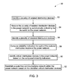
- FIG. 3 is a flow chart representing the steps involved in a method 50 for automatically establishing a scale free network within the plurality of distribution devices in the power network in accordance with an embodiment of the invention.
- the method 50 includes identifying isolated distribution devices in the power network in step 52.
- the isolated distribution devices are identified by computing a graph Laplacian matrix of the distribution devices in the power network.
- eigenvalues and eigenvectors of each of the distribution devices are determined and provided in the graph Laplacian matrix.
- the eigenvalues and the corresponding eigenvectors are examined to identify the isolated distribution devices.
- the isolated distribution devices are automatically restored by activating the tie switch in the power network.
- the unrestored isolated distribution devices are restored manually.
- the restored distribution devices are identified in step 56.
- the restored distribution devices are identified by computing a graph Laplacian matrix of the restored distribution devices in the power network.
- eigenvalues and eigenvectors of each of the restored distribution devices are determined and provided in the graph Laplacian matrix.
- the eigenvalues and the corresponding eigenvectors of the restored distribution devices are examined to identify the restored distribution devices. Subsequently, the reliability indicators for each of the distribution devices in the power network are computed in step 58.
- the computed reliability indicators include system average interruption duration index (SAIDI), system average interruption frequency index (SAIFI), momentary average interruption frequency index (MAIFI), customer average interruption duration index (CAIDI) and customer average interruption frequency index (CAIFI).
- SAIDI system average interruption duration index
- SAIFI system average interruption frequency index
- MAIFI momentary average interruption frequency index
- CAIDI customer average interruption duration index
- CAIFI customer average interruption frequency index
- critical distribution devices are identified by comparing the computed reliability indicators of each of the distribution devices.
- criticalness of a distribution device is directly proportional to the impact of the distribution device on the electric power network reliability. If the impact of the distribution device is higher, the criticalness of the distribution device is higher.
- ranks are provided for each of the distribution devices based on the comparison of the computed reliability indicators.
- the ranks of the distribution devices are provided for corresponding values of the reliability indicators in a descending order.
- a distribution device with higher SAIDI will be assigned a higher rank.
- a scale free communication network is established within the power network based on the identified critical distribution devices in step 62.
- an optimum number of communications paths dedicated to a distribution device is calculated based on the impact to overall power system reliability by the protection device of the distribution devices.
- a distribution device is assigned a larger number of communications links if its protection device has a larger impact on electric power system reliability.
- FIG. 4 is an example schematic representation of a scale free communication network 70 provided in the power network 20 in accordance with an embodiment of the invention.
- the distribution devices 22, 26, 28, 30, 32, 34, 36, 38, 40 and tie-switch 46 are communicatively coupled to form the scale free communication network 70 with a preferred medium of communication according to the above mentioned method.
- the tie-switch 46 includes the distribution device.
- the term "scale free network” is defined as a network whose degree distribution follows a power law, at least asymptotically, that is, the fraction P ( k ) of nodes in the network having k connections to other nodes goes for large values of k as P ( k ) ⁇ ck - ⁇ where c is a normalization constant and ⁇ is a parameter whose value is typically in the range 2 ⁇ ⁇ ⁇ 3, although occasionally it may lie outside these bounds.
- the preferred medium of communication includes private and public wired and wireless networks, and any combination thereof. Examples of such networks include WIFI, WIMAX, power line carrier, land line telephony, electric utility radio or cellular telephony.
- the tie-switch 46 possesses the highest value of the reliability indicators and would be assigned a first rank.
- the distribution device 22 possesses a medium value of the reliability indicators and is assigned a second rank.
- the distribution device 34 possesses a lowest value among the three distribution devices 22, 46 and 34 and would be assigned a third rank.
- the criticality of the distribution device is identified such as distribution device 24 being the most critical.
- highest redundancy is provided to the distribution device 46 followed by the distribution device 22 and 34 respectively.
- the term "redundancy" is defined as the number of communication links through which a distribution device is capable of communicating simultaneously with other distribution devices.
- distribution device 22 communicates with the distribution device 30 via the distribution device 28. However, in case of a communication fault at the distribution device 28, the distribution device 22 can reach the distribution device 30 via the distribution device 46 with only one hop.
- communication fault relates to a fault that has occurred in the communication system of the distribution device and excludes any power fault described below.
- the term "hop" is defined as a single communication path provided between two distribution devices. Therefore, the distribution device 22 employs an alternative route to transmit the message that reaches the distribution device 30 with the least number of hops. As understood, the most critical distribution device will have the highest redundancy and would be able to communicate with most number of distribution devices in the communication network resulting in highest number of alternative paths to reach a particular distribution device.
- FIG. 5 is an example schematic representation of the power network 20 including a power fault 64 in accordance with an embodiment of the invention.
- tie switch 46 is in an open state.
- the term "power fault” relates to a fault that occurs in the power network, in which one or more distribution devices operate to isolate the fault, resulting in a loss of power downstream to other distribution devices in the power network, resulting in an outage.
- the power fault 64 occurs between the distribution device 22 and 28.
- the substation 42 is feeding the distribution device 22 but the distribution device 22 has interrupted the flow of power downstream to the faulted section that leads to an outage and interruption to the customers downstream.
- the distribution device 22 communicates with the distribution device 28 to open and subsequently communicates with tie-switch 46 to close.
- the closed tie-switch 46 enables the power transfer from the substation 44 to feed the customers located between distribution devices 24, 28, 32 and 36 suffering from the outage.
- the communication between distribution devices 22, 28 and 46 can be understood better with respect to FIG. 6 described below.
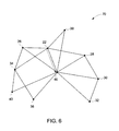
- FIG. 6 is the example schematic representation of the scale free communication network 70 provided in the power network 20 depicting communication between the distribution devices 22 and 46 in accordance with an embodiment of the invention.
- the distribution device 22 directly communicates with the tie-switch 46 without any hops and undesired delay. Therefore, the supply of power to the distribution devices 46, 28, 32 and 36 is restored instantly resulting in minimum interruption and maximum reliability.
- the various embodiments of the method described above provide an efficient way to minimize outage and maximize reliability in a power network.
- the method described above automatically establishes a new scale free communication topology that allows the distribution devices in the power network to communicate with each other in minimum number of hops and minimum delay.
- the scale free communication topology identifies critical distribution devices and provides a plurality of communication links to the critical distribution devices for communicating with the other distribution devices in the power network resulting in minimum outage and least number of customers being affected by the outage.
Landscapes
- Engineering & Computer Science (AREA)
- Power Engineering (AREA)
- Computer Networks & Wireless Communication (AREA)
- Signal Processing (AREA)
- Remote Monitoring And Control Of Power-Distribution Networks (AREA)
- Small-Scale Networks (AREA)
Abstract
A scale free communication network in a power network is provided. The scale free communication network comprises a plurality of distribution devices communicatively coupled to each other in a power network that include a protection device and a controller coupled to each of the plurality of distribution devices in the power network. The controller identifies a plurality of isolated distribution devices. The controller further restores the plurality of isolated distribution devices in the power network by automatically activating the tie-switch in the power network. The controller also computes reliability indicators for each of the restored distribution device in the power network. Furthermore, the controller identifies critical distribution devices in the power network based on the computed reliability indicators and establishes a scale free communications network within the power network based on the identified critical distribution devices.
Description
- A smart grid delivers electricity to consumers while leveraging digital communication and control technologies to minimize financial cost, save energy, and increase reliability. If designed properly, the smart grid will have a significant impact on improving a wide range of aspects in the electric power generation and distribution industry. Examples include self-healing, high-reliability, resistance to cyber-attack, accommodation of a wide variety of types of distributed generation and storage mechanisms, optimized asset allocation, and minimization of operation and maintenance expenses as well as high-resolution market control that incorporates advanced metering and demand-response.
- An important component in operation of smart grids is fault detection, isolation, and restoration of the smart grid. Today, most of the distribution devices in a power network are communicatively coupled either in a star, mesh or a ring topology. The aforementioned communication topologies leads to a delay in detection of faults that occur at the distribution devices located far from the substation. The delay in detection of the fault results in less than optimal isolation of faults and a larger than necessary number of consumers experiencing service outages during the faults. Furthermore, restoration of power networks operating on these communication topologies is delayed and inefficient as these communication topologies lead to undesired congestion, collisions due to simultaneous transmissions and undue computations and management of distribution devices within the power network.
- For these and other reasons, there is a need for embodiments of the invention.
- A scale free communication network in a power network is provided. The scale free communication network includes a plurality of distribution devices communicatively coupled to each other in a power network that include a protection device and a controller coupled to each of the plurality of distribution devices in the power network. The controller identifies a plurality of isolated distribution devices. The controller further restores the plurality of isolated distribution devices in the power network by automatically activating the tie-switch in the power network. The controller also computes reliability indicators for each of the restored distribution device in the power network. Furthermore, the controller identifies critical distribution devices in the power network based on the computed reliability indicators and establishes a scale free communications network within the power network based on the identified critical distribution devices.
- These and other features and, aspects of the present invention will become better understood when the following detailed description is read with reference to the accompanying drawings in which like characters represent like parts throughout the drawings, wherein:
-
FIG. 1 is a diagrammatical representation of a distribution device in accordance with an example embodiment of the invention. -
FIG. 2 is an example representation of a power network including a plurality of distribution devices coupled to each other in accordance with an example embodiment of the invention. -
FIG. 3 is a flow chart representing the steps involved in a method for automatically establishing a scale free communications network within the plurality of distribution devices in the power network in accordance with an embodiment of the invention. -
FIG. 4 is an example schematic representation of a scale free communication network provided in the power network in accordance with an embodiment of the invention. -
FIG. 5 is an example schematic representation of the power network including a power fault in accordance with an embodiment of the invention. -
FIG. 6 is an example schematic representation of the scale free communication network provided in the power network depicting communication between the - Embodiments of the present invention include a scale free communication network. The scale free communication network in a power network comprises a plurality of distribution devices communicatively coupled to each other in a power network that include a protection device and a controller coupled to each of the plurality of distribution devices in the power network. The controller identifies a plurality of isolated distribution devices. The controller restores the plurality of isolated distribution devices in the power network by automatically opening identified distribution devices and activating the tie-switch in the power network. The controller also identifies a plurality of restored distribution devices and computes reliability indicators for each of the restored distribution device in the power network. Furthermore, the controller identifies critical distribution devices in the power network based on the computed reliability indicators and establishes a scale free communications network within the power network based on the identified critical distribution devices.
- Power networks include multiple distribution devices electrically coupled to each other over long distances for transmission and distribution of power. The distribution devices in the power network communicate with each other based on a communication topology via a preferred medium of communication. A star, ring or a mesh topology can be provided for communication between the distribution devices. In operation, during a fault, the distribution devices send a fault message to the other distribution devices according to the topology in which the distribution devices are communicatively coupled. However, the communication topologies may result in undesired delay and power outage.
- A communications network that incorporates the reliability of a mesh network with the reduced complexity of a star or ring network can be used in the power network. In this arrangement, the redundant communication paths between each node are scaled back based on specified reliability requirements, such a network architecture can be referred to as a scale free network. This communication topology for the power networks is described below.
-
FIG. 1 is a diagrammatical representation of adistribution device 10 in accordance with an example embodiment of the invention. Thedistribution device 10 includes aprotection device 12 and acontroller 14 mounted on thedistribution device 10. In one embodiment, thedistribution device 10 may include an electrical pole. In another embodiment, theprotection device 12 includes a recloser, a relay, distance protection devices, differential protection devices, phasor based protection devices, current limiting devices and high power electronic devices. In other embodiments, thecontroller 14 can be integrated with theprotection device 12. The controller is responsible for communicating within a power network and controls the operations of the protection device based on such communications. -
FIG. 2 is an example representation of apower network 20 including a plurality of distribution devices coupled to each other in accordance with an example embodiment of the invention. Thepower network 20 includesdistribution devices power network 20 further includessubstations power network 20 via thedistribution devices switch 46 is connected to the power network via thedistribution devices substations power network 20. Furthermore, when thepower network 20 is first deployed and commissioned, thedistribution devices power network 20. The method for establishing the scale free communication network in thepower network 20 is described below in detail. -
FIG. 3 is a flow chart representing the steps involved in amethod 50 for automatically establishing a scale free network within the plurality of distribution devices in the power network in accordance with an embodiment of the invention. Themethod 50 includes identifying isolated distribution devices in the power network instep 52. In one embodiment, the isolated distribution devices are identified by computing a graph Laplacian matrix of the distribution devices in the power network. In another embodiment, eigenvalues and eigenvectors of each of the distribution devices are determined and provided in the graph Laplacian matrix. In yet another embodiment, the eigenvalues and the corresponding eigenvectors are examined to identify the isolated distribution devices. Instep 54, the isolated distribution devices are automatically restored by activating the tie switch in the power network. In one embodiment, the unrestored isolated distribution devices are restored manually. The restored distribution devices are identified instep 56. In one embodiment, the restored distribution devices are identified by computing a graph Laplacian matrix of the restored distribution devices in the power network. In another embodiment, eigenvalues and eigenvectors of each of the restored distribution devices are determined and provided in the graph Laplacian matrix. In yet another embodiment, the eigenvalues and the corresponding eigenvectors of the restored distribution devices are examined to identify the restored distribution devices. Subsequently, the reliability indicators for each of the distribution devices in the power network are computed instep 58. In an example embodiment, the computed reliability indicators include system average interruption duration index (SAIDI), system average interruption frequency index (SAIFI), momentary average interruption frequency index (MAIFI), customer average interruption duration index (CAIDI) and customer average interruption frequency index (CAIFI). Instep 60, critical distribution devices are identified by comparing the computed reliability indicators of each of the distribution devices. As used herein, criticalness of a distribution device is directly proportional to the impact of the distribution device on the electric power network reliability. If the impact of the distribution device is higher, the criticalness of the distribution device is higher. In one embodiment, ranks are provided for each of the distribution devices based on the comparison of the computed reliability indicators. In another embodiment, the ranks of the distribution devices are provided for corresponding values of the reliability indicators in a descending order. For example, a distribution device with higher SAIDI will be assigned a higher rank. Subsequently, a scale free communication network is established within the power network based on the identified critical distribution devices instep 62. In one embodiment an optimum number of communications paths dedicated to a distribution device is calculated based on the impact to overall power system reliability by the protection device of the distribution devices. In an example embodiment, a distribution device is assigned a larger number of communications links if its protection device has a larger impact on electric power system reliability. -
FIG. 4 is an example schematic representation of a scalefree communication network 70 provided in thepower network 20 in accordance with an embodiment of the invention. Thedistribution devices switch 46 are communicatively coupled to form the scalefree communication network 70 with a preferred medium of communication according to the above mentioned method. In one embodiment, the tie-switch 46 includes the distribution device. As used herein, the term "scale free network" is defined as a network whose degree distribution follows a power law, at least asymptotically, that is, the fraction P(k) of nodes in the network having k connections to other nodes goes for large values of k as P(k)∼ck -γ where c is a normalization constant and γ is a parameter whose value is typically in therange 2 < γ < 3, although occasionally it may lie outside these bounds. In one embodiment, the preferred medium of communication includes private and public wired and wireless networks, and any combination thereof. Examples of such networks include WIFI, WIMAX, power line carrier, land line telephony, electric utility radio or cellular telephony. For example, taking thedistribution devices switch 46 possesses the highest value of the reliability indicators and would be assigned a first rank. Thedistribution device 22 possesses a medium value of the reliability indicators and is assigned a second rank. Thedistribution device 34 possesses a lowest value among the threedistribution devices distribution device 24 being the most critical. Subsequently, highest redundancy is provided to thedistribution device 46 followed by thedistribution device - For example, during normal operation,
distribution device 22 communicates with thedistribution device 30 via thedistribution device 28. However, in case of a communication fault at thedistribution device 28, thedistribution device 22 can reach thedistribution device 30 via thedistribution device 46 with only one hop. As used herein, the term "communication fault" relates to a fault that has occurred in the communication system of the distribution device and excludes any power fault described below. As used herein, the term "hop" is defined as a single communication path provided between two distribution devices. Therefore, thedistribution device 22 employs an alternative route to transmit the message that reaches thedistribution device 30 with the least number of hops. As understood, the most critical distribution device will have the highest redundancy and would be able to communicate with most number of distribution devices in the communication network resulting in highest number of alternative paths to reach a particular distribution device. -
FIG. 5 is an example schematic representation of thepower network 20 including apower fault 64 in accordance with an embodiment of the invention. In normal operation,tie switch 46 is in an open state. As used herein, the term "power fault" relates to a fault that occurs in the power network, in which one or more distribution devices operate to isolate the fault, resulting in a loss of power downstream to other distribution devices in the power network, resulting in an outage. For example, in operation, thepower fault 64 occurs between thedistribution device substation 42 is feeding thedistribution device 22 but thedistribution device 22 has interrupted the flow of power downstream to the faulted section that leads to an outage and interruption to the customers downstream. Consequently, to restore power to customers located on the healthy section of the distribution feeder, betweendistribution device 28 and thetie switch 46, thedistribution device 22 communicates with thedistribution device 28 to open and subsequently communicates with tie-switch 46 to close. The closed tie-switch 46 enables the power transfer from thesubstation 44 to feed the customers located betweendistribution devices distribution devices FIG. 6 described below. -
FIG. 6 is the example schematic representation of the scalefree communication network 70 provided in thepower network 20 depicting communication between thedistribution devices power fault 64, thedistribution device 22 directly communicates with the tie-switch 46 without any hops and undesired delay. Therefore, the supply of power to thedistribution devices - The various embodiments of the method described above provide an efficient way to minimize outage and maximize reliability in a power network. Generally, the method described above automatically establishes a new scale free communication topology that allows the distribution devices in the power network to communicate with each other in minimum number of hops and minimum delay. Furthermore, the scale free communication topology identifies critical distribution devices and provides a plurality of communication links to the critical distribution devices for communicating with the other distribution devices in the power network resulting in minimum outage and least number of customers being affected by the outage.
- It is to be understood that a skilled artisan will recognize the interchangeability of various features from different embodiments and that the various features described, as well as other known equivalents for each feature, may be mixed and matched by one of ordinary skill in this art to construct additional systems and techniques in accordance with principles of this disclosure. It is, therefore, to be understood that the appended claims are intended to cover all such modifications and changes as fall within the scope of the invention as defined therein.
- While only certain features of the invention have been illustrated and described herein, many modifications and changes will occur to those skilled in the art. It is, therefore, to be understood that the appended claims are intended to cover all such modifications and changes as fall within the scope of the invention as defined therein.
Claims (15)
- A method for communicating within a power network, comprising:identifying (52) a plurality of isolated distribution devices;restoring (54) the plurality of isolated distribution devices in the power network by automatically activating the tie-switch in the power network;computing (58) reliability indicators for each of the distribution devices in the power network;identifying (60) critical distribution devices in the power network based on the computed reliability indicators; andestablishing (62) a scale free communications network within the power network based on the identified critical distribution devices.
- The method of claim 1, wherein identifying the plurality of isolated distribution devices comprises computing a graph Laplacian matrix of the distribution devices.
- The method of claim 1 or claim 2, wherein identifying the plurality of isolated distribution devices comprises determining eigenvalues and eigenvectors of the graph representation of the distribution devices.
- The method of claim 1, 2 or 3, wherein identifying the plurality of isolated distribution devices comprises: examining the eigenvalues of the distribution devices and/or examining the eigenvectors of the corresponding eigenvalues of the distribution devices.
- The method of any preceding claim, wherein identifying the plurality of restored distribution devices comprises computing a graph Laplacian matrix of the restored distribution devices.
- The method of any preceding claim, wherein identifying the plurality of restored distribution devices comprises: determining eigenvalues and eigenvectors of the graph representation of the restored distribution devices.
- The method of any preceding claim, wherein identifying the plurality of restored distribution devices comprises: examining the eigenvalues of the graph representation of the restored distribution devices, and/or examining the eigenvectors of the corresponding eigenvalues of the restored distribution devices.
- The method of any preceding claim, wherein computing reliability indicators comprises computing system average interruption duration index (SAIDI), system average interruption frequency index (SAIFI), momentary average interruption frequency index (MAIFI), customer average interruption duration index (CAIDI) and customer average interruption frequency index (CAIFI) independently.
- The method of any preceding claim, wherein identifying the critical distribution devices comprises comparing the computed reliability indicators of each of the restored distribution devices.
- The method of any preceding claim, wherein identifying the critical distribution devices comprises providing ranks to each of the restored distribution devices based on an impact of the critical distribution devices on the computed reliability indicators, wherein providing ranks to each of the restored distribution devices preferably comprises providing ranks corresponding to the values of the reliability indicators in a descending order.
- A non-transitory computer-readable medium comprising computer-readable instructions of a computer program that, when executed by a processor, cause the processor to perform a method of any one of claims 1 to 10.
- A system comprising:a plurality of distribution devices (22, 34) communicatively coupled to each other in a power network (20);a protection device coupled to each of the plurality of distribution devices (22, 34) configured to transmit power in the power network (20); anda controller coupled to each of the plurality of distribution devices (22, 34) configured to:identify a plurality of isolated distribution devices;restore the plurality of isolated distribution devices in the power network by automatically activating the tie-switch in the power network;identify a plurality of restored distribution devices;compute reliability indicators for each of the restored distribution device in the power network;identify critical distribution devices in the power network based on the computed reliability indicators; andestablish a scale free communications network within the power network based on the identified critical distribution devices.
- The system of claim 12, wherein at least one of:the distribution device comprises a utility pole or equipment vault;the power network comprises a transmission network or a distribution network; andthe protection device comprises a recloser.
- The system of claim 12 or claim 13, wherein the plurality of distribution devices are communicatively coupled to each other in a preferred mode of communication preferably comprising private and public wired and wireless networks, and any combination thereof.
- The system of claim 14, wherein the private and pulic wired and wireless networks comprises WIFI, WIMAX, power line carrier, land line telephony, electric utility radio or cellular telephony.
Applications Claiming Priority (1)
| Application Number | Priority Date | Filing Date | Title |
|---|---|---|---|
| US13/173,588 US8750118B2 (en) | 2011-06-30 | 2011-06-30 | Scale-free routing topology for a power network |
Publications (1)
| Publication Number | Publication Date |
|---|---|
| EP2544325A2 true EP2544325A2 (en) | 2013-01-09 |
Family
ID=47010164
Family Applications (1)
| Application Number | Title | Priority Date | Filing Date |
|---|---|---|---|
| EP12173931A Withdrawn EP2544325A2 (en) | 2011-06-30 | 2012-06-27 | Scale-free routing topology for a power network |
Country Status (7)
| Country | Link |
|---|---|
| US (1) | US8750118B2 (en) |
| EP (1) | EP2544325A2 (en) |
| JP (1) | JP2013017381A (en) |
| AU (1) | AU2012203848A1 (en) |
| BR (1) | BR102012016250A2 (en) |
| CA (1) | CA2782255A1 (en) |
| NZ (1) | NZ600971A (en) |
Cited By (1)
| Publication number | Priority date | Publication date | Assignee | Title |
|---|---|---|---|---|
| CN103724519A (en) * | 2012-10-11 | 2014-04-16 | 第一毛织株式会社 | Photocurable composition for packaging organic light emitting apparatus, encapsulated device and encapsulated apparatus |
Families Citing this family (4)
| Publication number | Priority date | Publication date | Assignee | Title |
|---|---|---|---|---|
| KR101403221B1 (en) | 2013-06-05 | 2014-06-02 | 이화여자대학교 산학협력단 | System and method for measuring utility usage using ring communication architecture and ortho code in smart grid environment |
| CN105720570B (en) * | 2014-12-05 | 2018-08-14 | 国家电网公司 | A kind of DC grid rack construction method |
| CN108736465B (en) * | 2017-04-24 | 2021-09-03 | 中国电力科学研究院 | Future-state power grid model construction method and device |
| CN118336639A (en) * | 2024-04-09 | 2024-07-12 | 江苏征途技术股份有限公司 | Low-voltage area self-healing control system and method |
Family Cites Families (12)
| Publication number | Priority date | Publication date | Assignee | Title |
|---|---|---|---|---|
| US20040172399A1 (en) | 2001-07-20 | 2004-09-02 | Saffre Fabrice T P | Method and apparatus for creating connections in networks |
| US7739138B2 (en) * | 2003-05-19 | 2010-06-15 | Trimble Navigation Limited | Automated utility supply management system integrating data sources including geographic information systems (GIS) data |
| US7852837B1 (en) * | 2003-12-24 | 2010-12-14 | At&T Intellectual Property Ii, L.P. | Wi-Fi/BPL dual mode repeaters for power line networks |
| US20070291663A1 (en) | 2006-06-19 | 2007-12-20 | Nokia Corporation | Method and apparatus for scale-free topology generation in relay based wireless networks |
| US20070298821A1 (en) | 2006-06-21 | 2007-12-27 | Lockheed Martin Corporation | System for boolean network configuration of a wireless network |
| US7940669B2 (en) * | 2007-06-15 | 2011-05-10 | Silver Spring Networks, Inc. | Route and link evaluation in wireless mesh communications networks |
| US7961740B2 (en) * | 2007-08-01 | 2011-06-14 | Silver Spring Networks, Inc. | Method and system of routing in a utility smart-grid network |
| US8279870B2 (en) * | 2007-08-01 | 2012-10-02 | Silver Spring Networks, Inc. | Method and system of routing in a utility smart-grid network |
| US7839899B2 (en) * | 2008-03-28 | 2010-11-23 | Silver Spring Networks, Inc. | Method and system of updating routing information in a communications network |
| US8311063B2 (en) * | 2008-03-28 | 2012-11-13 | Silver Spring Networks, Inc. | Updating routing and outage information in a communications network |
| US8121740B2 (en) * | 2008-12-18 | 2012-02-21 | Abb Research Ltd. | Feeder automation for an electric power distribution system |
| US20110254557A1 (en) * | 2009-07-20 | 2011-10-20 | Consolidated Edison Company Of New York, Inc. | Electromechanical relays including embedded sensors |
-
2011
- 2011-06-30 US US13/173,588 patent/US8750118B2/en not_active Expired - Fee Related
-
2012
- 2012-06-27 EP EP12173931A patent/EP2544325A2/en not_active Withdrawn
- 2012-06-28 JP JP2012144834A patent/JP2013017381A/en active Pending
- 2012-06-28 CA CA2782255A patent/CA2782255A1/en not_active Abandoned
- 2012-06-29 AU AU2012203848A patent/AU2012203848A1/en not_active Abandoned
- 2012-06-29 NZ NZ600971A patent/NZ600971A/en not_active IP Right Cessation
- 2012-06-29 BR BR102012016250-4A patent/BR102012016250A2/en not_active Application Discontinuation
Non-Patent Citations (1)
| Title |
|---|
| None |
Cited By (2)
| Publication number | Priority date | Publication date | Assignee | Title |
|---|---|---|---|---|
| CN103724519A (en) * | 2012-10-11 | 2014-04-16 | 第一毛织株式会社 | Photocurable composition for packaging organic light emitting apparatus, encapsulated device and encapsulated apparatus |
| CN103724519B (en) * | 2012-10-11 | 2016-08-24 | 第一毛织株式会社 | Photocurable composition, packaged type device and packaged device for encapsulating organic light emitting device |
Also Published As
| Publication number | Publication date |
|---|---|
| AU2012203848A1 (en) | 2013-01-17 |
| BR102012016250A2 (en) | 2013-11-05 |
| US8750118B2 (en) | 2014-06-10 |
| NZ600971A (en) | 2014-01-31 |
| US20130003603A1 (en) | 2013-01-03 |
| CA2782255A1 (en) | 2012-12-30 |
| JP2013017381A (en) | 2013-01-24 |
Similar Documents
| Publication | Publication Date | Title |
|---|---|---|
| US10680430B2 (en) | Fault recovery systems and methods for electrical power distribution networks | |
| EP2541717B1 (en) | System and method for automated fault control and restoration of smart grids | |
| JP4942454B2 (en) | Grid interconnection device and grid interconnection system | |
| EP2565656A2 (en) | Systems, methods, and apparatus for locating faults on an electrical distribution network | |
| US9853445B2 (en) | Method and system for monitoring an electrical power grid | |
| US8750118B2 (en) | Scale-free routing topology for a power network | |
| Tarhuni et al. | Autonomous control strategy for fault management in distribution networks | |
| US11107045B2 (en) | Smart meter based service ticket closing control | |
| US20190311444A1 (en) | Optimal Communication Architecture for Smart Distribution Power Grid | |
| CA3226832C (en) | Closed loop restoration | |
| JP2012196046A (en) | Method and device for sequentially correcting daily load prediction curve | |
| WO2009127817A1 (en) | Self organising unit protection | |
| CN110442939B (en) | Direct-current power distribution and utilization system reliability evaluation method based on network equivalence | |
| Melo et al. | Distribution automation on LV and MV using distributed intelligence | |
| Jamborsalamati et al. | Design, implementation and real-time testing of an IEC 61850 based FLISR algorithm for smart distribution grids | |
| CN106651639A (en) | Method and system for determining power guaranteeing operation mode based on reliability evaluation | |
| Slabbert et al. | Adaptive protection settings for medium voltage feeders | |
| D'adamo et al. | Smart fault selection: new operational criteria and challenges for the large-scale deployment in e-distribuzione's network | |
| Jamborsalamati et al. | Improvement of supply restoration in multi-spare-feeder active distribution grids using IEC 61850 | |
| EP3937344A1 (en) | Method for operating intelligent electronic device and an intelligent electronic device | |
| Botero et al. | Procedure of fault management in distribution networks with distributed generation | |
| US20220051353A1 (en) | Optimal Communication Architecture for Smart Distribution Power Grid | |
| John et al. | Reliability Assessment of Omu-Aran 132/33kV Transmission Substation feeders | |
| CN111009888A (en) | Self-adaptive distance protection method based on communication | |
| CN118472937A (en) | Main-distribution cooperative power grid power supply recovery method and device |
Legal Events
| Date | Code | Title | Description |
|---|---|---|---|
| PUAI | Public reference made under article 153(3) epc to a published international application that has entered the european phase |
Free format text: ORIGINAL CODE: 0009012 |
|
| AK | Designated contracting states |
Kind code of ref document: A2 Designated state(s): AL AT BE BG CH CY CZ DE DK EE ES FI FR GB GR HR HU IE IS IT LI LT LU LV MC MK MT NL NO PL PT RO RS SE SI SK SM TR |
|
| AX | Request for extension of the european patent |
Extension state: BA ME |
|
| STAA | Information on the status of an ep patent application or granted ep patent |
Free format text: STATUS: THE APPLICATION IS DEEMED TO BE WITHDRAWN |
|
| 18D | Application deemed to be withdrawn |
Effective date: 20160105 |