EP2543973B1 - Stromversorgungssystem für eine Electronic Flight Bag - Google Patents
Stromversorgungssystem für eine Electronic Flight Bag Download PDFInfo
- Publication number
- EP2543973B1 EP2543973B1 EP12175015.2A EP12175015A EP2543973B1 EP 2543973 B1 EP2543973 B1 EP 2543973B1 EP 12175015 A EP12175015 A EP 12175015A EP 2543973 B1 EP2543973 B1 EP 2543973B1
- Authority
- EP
- European Patent Office
- Prior art keywords
- electrical power
- aircraft
- flight bag
- electronic flight
- power source
- Prior art date
- Legal status (The legal status is an assumption and is not a legal conclusion. Google has not performed a legal analysis and makes no representation as to the accuracy of the status listed.)
- Active
Links
Images


Classifications
-
- G—PHYSICS
- G06—COMPUTING OR CALCULATING; COUNTING
- G06F—ELECTRIC DIGITAL DATA PROCESSING
- G06F1/00—Details not covered by groups G06F3/00 - G06F13/00 and G06F21/00
- G06F1/26—Power supply means, e.g. regulation thereof
- G06F1/28—Supervision thereof, e.g. detecting power-supply failure by out of limits supervision
-
- G—PHYSICS
- G01—MEASURING; TESTING
- G01C—MEASURING DISTANCES, LEVELS OR BEARINGS; SURVEYING; NAVIGATION; GYROSCOPIC INSTRUMENTS; PHOTOGRAMMETRY OR VIDEOGRAMMETRY
- G01C23/00—Combined instruments indicating more than one navigational value, e.g. for aircraft; Combined measuring devices for measuring two or more variables of movement, e.g. distance, speed or acceleration
-
- G—PHYSICS
- G06—COMPUTING OR CALCULATING; COUNTING
- G06F—ELECTRIC DIGITAL DATA PROCESSING
- G06F1/00—Details not covered by groups G06F3/00 - G06F13/00 and G06F21/00
- G06F1/26—Power supply means, e.g. regulation thereof
- G06F1/263—Arrangements for using multiple switchable power supplies, e.g. battery and AC
-
- G—PHYSICS
- G06—COMPUTING OR CALCULATING; COUNTING
- G06F—ELECTRIC DIGITAL DATA PROCESSING
- G06F1/00—Details not covered by groups G06F3/00 - G06F13/00 and G06F21/00
- G06F1/26—Power supply means, e.g. regulation thereof
- G06F1/266—Arrangements to supply power to external peripherals either directly from the computer or under computer control, e.g. supply of power through the communication port, computer controlled power-strips
-
- G—PHYSICS
- G06—COMPUTING OR CALCULATING; COUNTING
- G06F—ELECTRIC DIGITAL DATA PROCESSING
- G06F1/00—Details not covered by groups G06F3/00 - G06F13/00 and G06F21/00
- G06F1/26—Power supply means, e.g. regulation thereof
- G06F1/30—Means for acting in the event of power-supply failure or interruption, e.g. power-supply fluctuations
-
- B—PERFORMING OPERATIONS; TRANSPORTING
- B64—AIRCRAFT; AVIATION; COSMONAUTICS
- B64D—EQUIPMENT FOR FITTING IN OR TO AIRCRAFT; FLIGHT SUITS; PARACHUTES; ARRANGEMENT OR MOUNTING OF POWER PLANTS OR PROPULSION TRANSMISSIONS IN AIRCRAFT
- B64D45/00—Aircraft indicators or protectors not otherwise provided for
- B64D2045/0075—Adaptations for use of electronic flight bags in aircraft; Supports therefor in the cockpit
-
- Y—GENERAL TAGGING OF NEW TECHNOLOGICAL DEVELOPMENTS; GENERAL TAGGING OF CROSS-SECTIONAL TECHNOLOGIES SPANNING OVER SEVERAL SECTIONS OF THE IPC; TECHNICAL SUBJECTS COVERED BY FORMER USPC CROSS-REFERENCE ART COLLECTIONS [XRACs] AND DIGESTS
- Y02—TECHNOLOGIES OR APPLICATIONS FOR MITIGATION OR ADAPTATION AGAINST CLIMATE CHANGE
- Y02T—CLIMATE CHANGE MITIGATION TECHNOLOGIES RELATED TO TRANSPORTATION
- Y02T50/00—Aeronautics or air transport
- Y02T50/50—On board measures aiming to increase energy efficiency
Definitions
- the invention relates to an electronic flight bag for use on board an aircraft, and more specifically, to a power supply system for use with an on board electronic flight bag.
- the typical electronic flight bag includes an electronic storage device which acts as a container for storing various user-configurable flight-related objects, such as flight routes as defined by way-points, airport information that includes approach routes, associated flight charts or other desired charts, temporary flight restrictions, and weather information as well as any other user-defined data objects associated with the flight.
- the electronic flight bag may be used in corporate aircraft and may include one or more data objects that relate to the corporate policies with respect to flights.
- a control system for providing electrical power to an electronic flight bag device on an aircraft, the control system comprising a power switching component coupled to a plurality of electrical power sources and at least one electronic flight bag device; wherein the power switching component is operative and configured to selectively apply electrical power from at least one of the plurality of electrical power sources based upon a condition of the aircraft; wherein the plurality of electrical power sources include a primary electrical power source and an auxiliary electrical power source; and characterised in that the power switching component is coupled to the primary electrical power source via a primary feed line-in and to the auxiliary electrical power source via an auxiliary feed line-in; and the power switching component is configured to selectively couple the primary electrical power source to the electronic flight bag via a primary feed line and to selectively couple the auxiliary electrical power source to the electronic flight bag device via an auxiliary feed line.
- the power switching component is further operative and configured to couple only a single power source from the plurality of electrical power sources to the electronic flight bag device when a predetermined condition for the aircraft has occurred and is further operative and configured to couple at least first and second power sources from the plurality of electrical power sources to the electronic flight bag device when another predetermined condition for aircraft has occurred.
- the condition of the aircraft may be in a pre-determined condition.
- the power switching component may be further operative and configured to couple only a single power source from the plurality of electrical power sources to the electronic flight bag device when the aircraft is in the pre-determined condition.
- the power switching component may be further operative and configured to couple one of the first or second power sources from the plurality of electrical power sources to the electronic flight bag device when the aircraft is not in the pre-determined condition.
- the plurality of electrical power sources may consist of a primary electrical power source and an auxiliary electrical power source.
- the primary electrical power source may be selected from the group consisting of an electrical power generator, a fuel cell, a battery device, and an energy harvesting device.
- the primary electrical power source may consist of an electrical power generator device located on the aircraft and a secondary electrical power source when the aircraft is not in the pre-determined condition.
- the auxiliary electrical power source may be selected from the group consisting of an electrical power generator, a fuel cell, a battery device and an energy harvesting device.
- the power switching component may be coupled to at least first and second electronic flight bag devices.
- At least one of the electronic flight bag devices may be a portable self-contained device.
- the electronic flight bag control system comprises the power switching component coupled to the plurality of power sources, and at least one electronic flight bag device coupled to each of the plurality of power sources via the power switching component.
- the condition of the aircraft may be whether the aircraft is in a predetermined condition.
- the power switching component may be further operative and configured to couple only a single power source from the plurality of electrical power sources to the electronic flight bag device when the aircraft is in a predetermined condition.
- the power switching component may be further operative and configured to couple at least first or second power sources from the plurality of electrical power sources to the electronic flight bag device when the aircraft is not in the predetermined condition.
- the plurality of electrical power sources may consist of a primary electrical power source and a secondary electrical power source.
- the primary electrical power source may be selected from the group consisting of an electrical power generator, a fuel cell, a battery device, an energy harvesting device, and an external power source when the aircraft is in the predetermined condition.
- the primary electrical power source may consist of an electrical power generator source selected from the group consisting of an electrical power generator, a fuel cell, a battery device, an energy harvesting device, and an external power source when the aircraft is not in the predetermined condition.
- the auxiliary electrical power source may be selected from the group consisting of an electrical power generator, a fuel cell, a battery device, an energy harvesting device, and an external power source.
- the power switching component may be coupled to at least first and second electronic flight bag devices.
- a method for providing electrical power to an electronic flight bag device on an aircraft comprising the steps: providing a power switching component coupled to a plurality of electrical power sources; coupling at least one electronic flight bag device to each of the plurality of electrical power sources via the power switching component; determining if the aircraft is in a predetermined condition; applying electrical power via the power switching component from one of the plurality of electrical power sources to the at least one electronic flight bag device when the aircraft is determined to be in the predetermined condition; and applying electrical power via the power switching component from at least two of the plurality of electrical power sources to the at least one electronic flight bag device when the aircraft is determined to be not in the predetermined condition, wherein the plurality of power sources include a primary electrical power source; and an auxiliary electrical power source; wherein the power switching component is coupled to the primary electrical power source via a primary feed line-in and to the auxiliary electrical power source via an auxiliary feed line-in; and wherein the power switching component is coupled to the electronic flight
- Any feature in one aspect may be applied as a feature in any other aspect, in any combination.
- system features may be applied as method features and vice versa.
- the embodiments of this invention as discussed below are preferably a software algorithm, program or code residing on computer useable medium having control logic for enabling execution on a machine having a computer processor.
- the machine typically includes memory storage configured to provide output from execution of the computer algorithm or program.
- the present invention relates to an Electronic Flight Bag (EFB) for use on board an aircraft during flight.
- the electronic flight bag may be configured as a device integrated into the flight cockpit or as a standalone portable device which contains all of the information normally included in a physical flight bag that may be required and desired for a particular flight contained in furtherance of a paperless cockpit environment.
- the flight bag includes an electronic storage device configured as a container for storing various user-configurable flight-related objects.
- the electronic flight bag in accordance with the present invention is formed from user-confgured data objects so as to obviate the necessity of a physical flight bag.
- the electronic flight bag is typically populated with all data required and desired during a particular flight onto a standalone computing platform and carried on board the aircraft for use during a flight phase and thus avoids the necessity for a physical flight bag.
- Fig. 1 illustrates the life cycle of the electronic flight bag in accordance with the present invention.
- flight information required during a flight is assembled on the ground and carried aboard the aircraft for use during the flight.
- the electronic flight bag in accordance with the present invention emulates a physical flight bag in that it contains all of the information required and desired by a pilot during a particular flight.
- the electronic flight bag can be used in all of such applications.
- the user may select from various data objects and store those objects on an electronic storage medium or electronic container by way of a computing platform, such as a personal computer.
- a computing platform such as a personal computer.
- a user of the electronic flight bag in accordance with the present invention can load various flight-related objects, as discussed below, into the electronic container for use aboard the aircraft 22 during flight.
- This information can be obtained from various sources, including aircraft navigational data content providers, aircraft manufacturer content providers, as well as third-party content providers.
- the electronic container may be, for example, a standalone electronic medium, such as an electronic storage device, such as a diskette, flash card, flash drive or be hosted by a standalone computing environment, such as a personal computer 20 or a personal digital assistant (PDA), not shown.
- the electronic container may be portable and thus can be carried aboard an aircraft 22 and accessed during a flight phase and hosted by a computing platform. In order to avoid re-certification of the aircraft's existing on-board navigational system, the electronic container is hosted by a computing platform independent from the aircraft's on-board navigational system.
- the data in the electronic computer may be updated during flight and stored for use in future flights.
- FIG. 2 the electronic flight bag is illustrated graphically and identified with the reference numeral 24.
- the electronic flight bag 24 may contain various flight-related objects selectable by the user.
- Exemplary flight related objects may include flight routes, as defined by way-points, identified as track information 26; flight planning data 28; identified as airport information that includes approach routes; navigational charts 30; weather data 32; electronic text data 34; temporary flight-restriction data 36 and notes 38.
- the track 26 relates to route data, for example, data defined by various way-points.
- Flight planning data 28 may include various flight planning data, such as airport approaches.
- Electronic charts 30 may include various navigational charts, for example, such as available from www.jeppesen.com.
- Weather data 32 may consists of forecasted weather information, for example, from the National Weather Service, for the flight.
- the electronic text page object 34 may be used for various purposes. For example, for corporate users, electronic text pages may comprise the corporate policy with respect to corporate flights.
- the temporary flight-restrictions object 36 may include various temporary flight restrictions related to the flight. These temporary flight restrictions can be used to restrict air travel through particular airspace for various purposes and other restrictions as dictated by the Federal Aviation Administration.
- the notes object 38 can be used for any supplemental notes by the user or pilot.
- All of the above-mentioned data objects may be imported from various data sources and incorporated into the electronic flight bag 24 for use aboard the aircraft. Virtually any additional data objects can be added to the electronic flight bag. These data objects may be obtained from virtually any source and electronically stored in the electronic flight bag for later use aboard an aircraft.
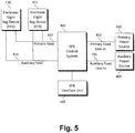
- EFB control system 400 coupled to a primary power source 402 and an auxiliary power source 404.
- the EFB control system 400 consists of any computer logic (e.g., software, source code or the like) driven component (e.g., computer processor) capable of performing actions, such as providing power feeds, based on instructions/logic.
- EFB control system 400 may consist of a discrete logic controlled relay component or a transistor component.
- the EFB control system 400 may be configured to be positioned external of an EFB device 410 (as illustrated in FIG. 3 ) or alternatively be integrated with an EFB device 410 so as to be located therewithin.
- the EFB control system 400 is configured and operative to provide automatic power switching operations based upon a state of the aircraft.
- the primary power source 402 and auxiliary power source 404 each preferably consists of a device configured to provide DC electrical power sufficient to power the EFB device 410 (e.g. 28V DC, 115VAC 400Hz, 28VDC, etc.).
- the primary power source 402 may be a electrical generator component driven by an aircraft engine and/or an external power source coupled to the aircraft when the aircraft is on ground and typically located at its terminal for providing electrical power thereto when the aircraft engine(s) is not operating.
- the primary power source 402 may also consist of an Auxiliary Power Unit (APU) device, a battery component, an energy harvesting like device, or the like.
- the auxiliary power source 404 it may consist of a battery or like device that provides a reliable electrical power source.
- the auxiliary power source may consist of a Ram Air Turbine (RAT) or like device.
- RAT Ram Air Turbine
- the EFB control system 400 is coupled or integrated into an EFB device 410 preferably via a primary power feed line 412 and a secondary power feed line 414.
- the EFB device 410 may be configured and operative as a device integrated into the flight cockpit of an aircraft (e.g., a permanently installed device) or may be configured and operative as standalone portable device (e.g., a tablet, laptop or other similar portable computer device) which contains all of the information normally included in a physical flight bag that may be required and desired for a particular flight contained in furtherance of a paperless cockpit environment as mentioned above.
- the EFB control system 400 is coupled to an EFB interface unit 420.
- the EFB Interface Unit 420 is preferably operative and configured to couple to numerous data generating systems/components of the aircraft for acquiring data from those systems/components and supplying it to the EFB control system 400 preferably in a proper data format.
- the EFB control system 400 couples to the primary power source 402 (via primary feed line-in 403) and to the auxiliary power source 404 (via auxiliary feed line-in 405).
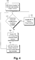
- the EFB control system 400 determines if a predetermined condition for the aircraft has been satisfied (e.g., is the aircraft on the ground or in the air (which can be achieved via a number of ways as would be appreciated by one skilled in the art (e.g., an air/ground switch)), or is an L1 door closed, or is any other predetermined condition for the aircraft satisfied which would be determinative of which power supply is to be coupled to the EFB device 410).
- a predetermined condition for the aircraft e.g., is the aircraft on the ground or in the air (which can be achieved via a number of ways as would be appreciated by one skilled in the art (e.g., an air/ground switch)
- an L1 door closed e.g., a predetermined condition for the aircraft satisfied which would be determinative of which power supply is to be coupled to the EFB device 410.
- the predetermined condition for the aircraft will be whether the aircraft is in flight or on the ground, however, as aforementioned, this flight/ground condition is not to be understood as the only predetermined condition for the aircraft (step 510) as it's only an illustrative predetermined condition.
- step 520 the EFB control system 400 couples the EFB device 410 to only the primary power source 402 (via primary feed line 412) since while in flight there should be no interruption of power from the primary power source 402, which thus significantly preserves the storage power integrity of the auxiliary power source 404 since it should not be needed absent a catastrophic condition.
- Process then returns to step 510 to determine if the state of the aircraft has changed while the primary power source is solely coupled to the EFB device 410.
- the EFB control system 400 couples the EFB device 410 to both the primary power source 402 (via primary feed line 412) and the auxiliary power source 404 (via auxiliary feed line 414) to ensure that there is no interruption of power to the EFB device 410 while the aircraft is on the ground.
- the EFB device 410 is then preferably operative and configured to automatically switch to the auxiliary power source 404 such that there was no interruption of electrical power supply to the EFB device 410.
- an interruption of electrical power to the EFB device 410 is disadvantageous. Process then returns to step 510 to determine if the state of the aircraft has changed while both the primary and auxiliary power sources are coupled to the EFB device 410.
- the invention provides switched power input based upon aircraft logic to avoid power loading limitations by permitting EFB connectivity to multiple aircraft power sources during ground operations when power is available via a battery source only and other non-normal situations.
- Optional embodiments of the present invention may also be said to broadly consist in the parts, elements and features referred to or indicated herein, individually or collectively, in any or all combinations of two or more of the parts, elements or features, and wherein specific integers are mentioned herein which have known equivalents in the art to which the invention relates, such known equivalents are deemed to be incorporated herein as if individually set forth.
- FIG. 5 shown is another illustrative embodiment in which the EFB control system 400 is shown coupled to first and second EFB devices (410, 411) wherein operation thereof is the same as described above with reference to illustrative embodiments of FIGS. 3 and 4 .
- the illustrative embodiment of FIG. 5 is not to be understood to be limited to only first and second EFB devices (410, 411) but rather may be coupled to any plurality of EFB devices.
Landscapes
- Engineering & Computer Science (AREA)
- Theoretical Computer Science (AREA)
- General Physics & Mathematics (AREA)
- Physics & Mathematics (AREA)
- General Engineering & Computer Science (AREA)
- Remote Sensing (AREA)
- Radar, Positioning & Navigation (AREA)
- Power Engineering (AREA)
- Aviation & Aerospace Engineering (AREA)
- Computer Hardware Design (AREA)
- Charge And Discharge Circuits For Batteries Or The Like (AREA)
- Direct Current Feeding And Distribution (AREA)
- Purses, Travelling Bags, Baskets, Or Suitcases (AREA)
- Power Sources (AREA)
Claims (10)
- Steuersystem, konfiguriert, um eine Electronic Flight Bag-Vorrichtung (24, 410) in einem Luftfahrzeug (22) mit elektrischem Strom zu versorgen, wobei das Steuersystem eine Stromschaltkomponente umfasst, die mit einer Vielzahl von elektrischen Stromquellen (402, 404) und zumindest einer Electronic Flight Bag-Vorrichtung (24, 410) gekoppelt ist;
wobei die Stromschaltkomponente betriebsfähig ist und konfiguriert, um selektiv elektrischen Strom von zumindest einer der Vielzahl von elektrischen Stromquellen basierend auf einem Zustand des Luftfahrzeugs (22) anzulegen;
wobei die Vielzahl von elektrischen Stromquellen eine primäre elektrische Stromquelle (402) und eine elektrische Hilfsstromquelle (404) beinhaltet; wobei
die Stromschaltkomponente mit der primären elektrischen Stromquelle über eine primäre Zuführungsleitung (403) und mit der elektrischen Hilfsstromquelle über eine Hilfszuführungsleitung (405) gekoppelt ist; und
die Stromschaltkomponente konfiguriert ist, um die primäre elektrische Stromquelle selektiv über eine primäre Zuführungsleitung (412) mit der Electronic Flight Bag zu koppeln und die elektrische Hilfsstromquelle selektiv über eine Hilfszuführungsleitung (414) mit der Electronic Flight Bag-Vorrichtung zu koppeln. - Steuersystem, konfiguriert, um eine Electronic Flight Bag-Vorrichtung (24, 410) in einem Luftfahrzeug (22) mit elektrischem Strom zu versorgen, nach Anspruch 1, wobei der Zustand des Luftfahrzeugs (22) ist, ob sich das Luftfahrzeug (22) in einem vorbestimmten Zustand befindet.
- Steuersystem, konfiguriert, um eine Electronic Flight Bag-Vorrichtung (24, 410) in einem Luftfahrzeug (22) mit elektrischem Strom zu versorgen, nach Anspruch 2, wobei die Stromschaltkomponente ferner betriebsfähig ist und konfiguriert, um nur eine einzelne elektrische Stromquelle der Vielzahl von elektrischen Stromquellen (402, 404) mit der Electronic Flight Bag-Vorrichtung (24, 410) zu koppeln, wenn sich das Luftfahrzeug (22) in dem vorbestimmten Zustand befindet.
- Steuersystem, konfiguriert, um eine Electronic Flight Bag-Vorrichtung (24, 410) in einem Luftfahrzeug (22) mit elektrischem Strom zu versorgen, nach Anspruch 3, wobei die Stromschaltkomponente ferner betriebsfähig ist und konfiguriert, um sowohl die primäre elektrische Stromquelle als auch die elektrische Hilfsstromquelle der Vielzahl von elektrischen Stromquellen (402, 404) mit der Electronic Flight Bag-Vorrichtung (24, 410) zu koppeln, wenn sich das Luftfahrzeug (22) nicht in dem vorbestimmten Zustand befindet.
- Steuersystem, konfiguriert, um eine Electronic Flight Bag-Vorrichtung (24, 410) in einem Luftfahrzeug (22) mit elektrischem Strom zu versorgen, nach Anspruch 4, wobei
die primäre elektrische Stromquelle (402) ausgewählt wird aus der Gruppe bestehend aus einem elektrischen Stromgenerator, einer Brennstoffzelle, einer Batterievorrichtung und einer Energiegewinnungsvorrichtung. - Steuersystem, konfiguriert, um eine Electronic Flight Bag-Vorrichtung (24, 410) in einem Luftfahrzeug (22) mit elektrischem Strom zu versorgen, nach Anspruch 5, wobei die primäre elektrische Stromquelle (402) aus einem elektrischen Stromgenerator besteht, der sich in dem Luftfahrzeug befindet.
- Steuersystem, konfiguriert, um eine Electronic Flight Bag-Vorrichtung (24, 410) in einem Luftfahrzeug (22) mit elektrischem Strom zu versorgen, nach Anspruch 6, wobei die elektrische Hilfsstromquelle (404) ausgewählt wird aus der Gruppe bestehend aus einem elektrischen Stromgenerator, einer Brennstoffzelle, einer Batterievorrichtung und einer Energiegewinnungsvorrichtung.
- Steuersystem, konfiguriert, um eine Electronic Flight Bag-Vorrichtung (24, 410) in einem Luftfahrzeug (22) mit elektrischem Strom zu versorgen, nach Anspruch 1, wobei die Stromschaltkomponente mit zumindest einer ersten und einer zweiten Electronic Flight Bag-Vorrichtung (24, 410) gekoppelt ist.
- Steuersystem, konfiguriert, um eine Electronic Flight Bag-Vorrichtung (24, 410) in einem Luftfahrzeug (22) mit elektrischem Strom zu versorgen, nach Anspruch 1, wobei zumindest eine der zumindest einen Electronic Flight Bag-Vorrichtung (24, 410) eine tragbare eigenständige Vorrichtung ist.
- Verfahren, um eine Electronic Flight Bag-Vorrichtung (24, 410) in einem Luftfahrzeug (22) mit elektrischem Strom zu versorgen, umfassend die folgenden Schritte:Bereitstellen einer Stromschaltkomponente, die mit einer Vielzahl von elektrischen Stromquellen (402, 404) gekoppelt ist;Koppeln von zumindest einer Electronic Flight Bag-Vorrichtung (24, 410) mit jeder der Vielzahl von elektrischen Stromquellen (402, 404) über die Stromschaltkomponente;Bestimmen, ob sich das Luftfahrzeug (22) in einem vorbestimmten Zustand befindet;Anlegen von elektrischem Strom über die Stromschaltkomponente von einer der Vielzahl von elektrischen Stromquellen (402, 404) an die zumindest eine Electronic Flight Bag-Vorrichtung (24), wenn festgestellt wird, dass sich das Luftfahrzeug (22) in dem vorbestimmten Zustand befindet; undAnlegen von elektrischem Strom über die Stromschaltkomponente von zumindest zwei der Vielzahl von elektrischen Stromquellen (402, 404) an die zumindest eine Electronic Flight Bag-Vorrichtung (24, 410), wenn festgestellt wird, dass sich das Luftfahrzeug (22) nicht in dem vorbestimmten Zustand befindet, wobei die Vielzahl von Stromquellen eine primäre elektrische Stromquelle und eine elektrische Hilfsstromquelle (404) beinhaltet;wobei die Stromschaltkomponente mit der primären elektrischen Stromquelle über eine primäre Zuführungsleitung (403) und mit der elektrischen Hilfsstromquelle über eine Hilfszuführungsleitung (405) gekoppelt ist; undwobei die Stromschaltkomponente mit der Electronic Flight Bag-Vorrichtung (24, 410) über eine primäre Zuführungsleitung (412) und über eine Hilfszuführungsleitung (414) gekoppelt ist.
Applications Claiming Priority (1)
| Application Number | Priority Date | Filing Date | Title |
|---|---|---|---|
| US13/176,637 US9347790B2 (en) | 2011-07-05 | 2011-07-05 | Power supply system with at least a primary power source and an auxiliary power source for powering an electronic flight bag depending on an whether an aircraft is in a flight condition |
Publications (3)
| Publication Number | Publication Date |
|---|---|
| EP2543973A2 EP2543973A2 (de) | 2013-01-09 |
| EP2543973A3 EP2543973A3 (de) | 2014-01-08 |
| EP2543973B1 true EP2543973B1 (de) | 2018-05-23 |
Family
ID=46639304
Family Applications (1)
| Application Number | Title | Priority Date | Filing Date |
|---|---|---|---|
| EP12175015.2A Active EP2543973B1 (de) | 2011-07-05 | 2012-07-04 | Stromversorgungssystem für eine Electronic Flight Bag |
Country Status (5)
| Country | Link |
|---|---|
| US (2) | US9347790B2 (de) |
| EP (1) | EP2543973B1 (de) |
| CN (1) | CN102868212B (de) |
| BR (1) | BR102012016361A2 (de) |
| CA (1) | CA2782060C (de) |
Families Citing this family (8)
| Publication number | Priority date | Publication date | Assignee | Title |
|---|---|---|---|---|
| US10298718B1 (en) * | 2008-03-17 | 2019-05-21 | Aviation Communication & Surveillance Systems, Llc | Method and apparatus to provide integrity monitoring of a safety critical application on a non-safety-critical platform |
| US20140035363A1 (en) | 2009-09-25 | 2014-02-06 | Pucline, Llc | Electrical power supplying device having a central power-receptacle assembly supplying electrical power to power plugs, adaptors and modules while concealed from view and managing excess power cord during power supplying operations |
| US8838300B2 (en) * | 2012-04-12 | 2014-09-16 | The Boeing Company | Standby aircraft management system |
| FR2998128B1 (fr) * | 2012-11-13 | 2016-10-07 | Microturbo | Calculateur de turbo-machine d'aeronef |
| FR3001289B1 (fr) * | 2013-01-18 | 2016-02-05 | Thales Sa | Systeme de sauvegarde de donnees aeronautiques d'un dispositif mobile sur une station d'accueil |
| US9927837B2 (en) | 2013-07-03 | 2018-03-27 | Pucline, Llc | Electrical power supplying system having an electrical power supplying docking station with a multi-function module for use in diverse environments |
| CN105738657A (zh) * | 2016-02-18 | 2016-07-06 | 江西洪都航空工业集团有限责任公司 | 一种飞行器测控系统自动供电装置 |
| CN107832073A (zh) * | 2017-11-24 | 2018-03-23 | 中国航空工业集团公司西安航空计算技术研究所 | 一种基于代理的机载智能电源模块升级维护方法 |
Citations (1)
| Publication number | Priority date | Publication date | Assignee | Title |
|---|---|---|---|---|
| US20080238191A1 (en) * | 2007-03-26 | 2008-10-02 | Champion Aerospace, Inc. | Power supply unit for use with an aircraft electrical system |
Family Cites Families (19)
| Publication number | Priority date | Publication date | Assignee | Title |
|---|---|---|---|---|
| US5899411A (en) * | 1996-01-22 | 1999-05-04 | Sundstrand Corporation | Aircraft electrical system providing emergency power and electric starting of propulsion engines |
| US6977482B2 (en) * | 2003-02-11 | 2005-12-20 | O2Micro International Limited | Selector circuit for power management in multiple battery systems |
| US6806589B1 (en) * | 2003-07-21 | 2004-10-19 | Hamilton Sundstrand Corporation | No break electric power transfer system |
| US7406623B2 (en) * | 2003-09-29 | 2008-07-29 | Hitachi Computer Peripherals Co., Ltd. | DC backup power supply system and disk array using same |
| US7769501B2 (en) | 2004-06-23 | 2010-08-03 | The Boeing Company | User-configurable electronic flight bag |
| US7364116B2 (en) * | 2004-09-27 | 2008-04-29 | The Boeing Company | Automatic control systems for aircraft auxiliary power units, and associated methods |
| US7656637B2 (en) | 2004-10-12 | 2010-02-02 | The Boeing Company | Power control system pseudo power-up, aircraft including the power control system and method of controlling power in an aircraft |
| US20060098358A1 (en) | 2004-11-08 | 2006-05-11 | Wambsganss Peter M | Power supply configured to detect a power source |
| FR2884804B1 (fr) * | 2005-04-21 | 2008-12-12 | Airbus France Sas | Dispositf source de secours electrique dispose sur un aeronef |
| US7859874B2 (en) | 2006-05-01 | 2010-12-28 | Rosemount Areospace Inc. | Universal AC or DC aircraft device power supply having power factor correction |
| CN101563829B (zh) | 2006-06-01 | 2012-07-04 | 埃克弗洛普公司 | 数据中心不间断配电架构 |
| US7875989B2 (en) * | 2007-09-04 | 2011-01-25 | Lycoming Engines, A Division Of Avco Corporation | Power source for aircraft engine controller systems |
| US20100084118A1 (en) | 2008-08-21 | 2010-04-08 | Airbus Operations | Cooling system for aircraft electric or electronic devices |
| US8650411B2 (en) * | 2008-09-07 | 2014-02-11 | Schweitzer Engineering Laboratories Inc. | Energy management for an electronic device |
| FR2937487B1 (fr) * | 2008-10-22 | 2010-11-26 | Airbus France | Dispositif et procede de communication entre un systeme informatique portable et des equipements avioniques |
| US9413264B2 (en) * | 2009-12-07 | 2016-08-09 | Illinois Tool Works Inc. | Ground power unit for aircraft |
| US8424800B2 (en) * | 2010-06-23 | 2013-04-23 | Hamilton Sundstrand Corporation | Multi-source emergency power optimization |
| CN201789331U (zh) * | 2010-08-06 | 2011-04-06 | 四川长虹电器股份有限公司 | 飞机发动机电源系统 |
| US8820677B2 (en) * | 2011-06-18 | 2014-09-02 | Jason A. Houdek | Aircraft power systems and methods |
-
2011
- 2011-07-05 US US13/176,637 patent/US9347790B2/en active Active
-
2012
- 2012-06-29 CA CA2782060A patent/CA2782060C/en active Active
- 2012-07-02 BR BRBR102012016361-6A patent/BR102012016361A2/pt not_active Application Discontinuation
- 2012-07-04 EP EP12175015.2A patent/EP2543973B1/de active Active
- 2012-07-05 CN CN201210231701.7A patent/CN102868212B/zh active Active
-
2016
- 2016-04-22 US US15/136,589 patent/US9811138B2/en active Active
Patent Citations (1)
| Publication number | Priority date | Publication date | Assignee | Title |
|---|---|---|---|---|
| US20080238191A1 (en) * | 2007-03-26 | 2008-10-02 | Champion Aerospace, Inc. | Power supply unit for use with an aircraft electrical system |
Also Published As
| Publication number | Publication date |
|---|---|
| BR102012016361A2 (pt) | 2014-04-29 |
| CA2782060A1 (en) | 2013-01-05 |
| US20160239064A1 (en) | 2016-08-18 |
| EP2543973A3 (de) | 2014-01-08 |
| US9347790B2 (en) | 2016-05-24 |
| CA2782060C (en) | 2015-08-04 |
| CN102868212A (zh) | 2013-01-09 |
| CN102868212B (zh) | 2018-06-08 |
| US9811138B2 (en) | 2017-11-07 |
| EP2543973A2 (de) | 2013-01-09 |
| US20130013935A1 (en) | 2013-01-10 |
Similar Documents
| Publication | Publication Date | Title |
|---|---|---|
| US9811138B2 (en) | Power supply system for an electronic flight bag | |
| EP1610094B1 (de) | Elektronische Flugtasche | |
| US8888046B2 (en) | Fuel management system | |
| EP2525337A2 (de) | Aufgerüstetes Flugmanagementsystem und Verfahren zur Bereitstellung davon | |
| US8706323B2 (en) | Aircraft dispatch information | |
| US10530153B2 (en) | Method and apparatus for operating a power system architecture | |
| CN105173096B (zh) | 视觉燃料预测器系统 | |
| Smaili et al. | Intelligent flight control systems evaluation for loss-of-control recovery and prevention | |
| US8433458B2 (en) | Method and device for assisting in the preparation and management of missions in an aircraft | |
| Denney et al. | Argument-based airworthiness assurance of small UAS | |
| US20230148132A1 (en) | Systems and methods for power transfer and load management | |
| Treacy | Flight safety issues of an all-electric aircraft | |
| Casarosa et al. | Impact of safety requirements on the weight of civil unmanned aerial vehicles | |
| CN120220476B (zh) | 飞行器的检查控制方法、电子设备及飞行器 | |
| Morlang et al. | Commercial space transportation and air traffic insertion-SESAR requirements and the European perspective | |
| Takahashi | iPad's in the cockpit: Evolution or revolution in the sky | |
| Fox | The EU's Direction of Air Travel: Charting the Flight Plan to Realise a “Droning” Ambition | |
| Lytle | Pilot perception of Electronic Flight Bags at Part 121 air carriers | |
| Burian et al. | Operating documents that change in real-time: Dynamic documents and user performance support | |
| Bailey Fausset et al. | Friendlier skies: Development of electronic checklists for emergency procedures for the kc-135 stratotanker | |
| Jones et al. | Systems analysis of NASA aviation safety program | |
| Capper | Tanker Fuel Efficiency: Saving Through Receiver Fuel Planning | |
| Yang | The Feasibility Study of Airborne Image Recordings for Aircraft Accident Investigation | |
| Saur et al. | Design and implementation of electrical load analysis for cross fleet configuration | |
| Lacher | Research Challenges Associated with Unmanned Aircraft Systems Airspace Integration |
Legal Events
| Date | Code | Title | Description |
|---|---|---|---|
| PUAI | Public reference made under article 153(3) epc to a published international application that has entered the european phase |
Free format text: ORIGINAL CODE: 0009012 |
|
| 17P | Request for examination filed |
Effective date: 20120704 |
|
| AK | Designated contracting states |
Kind code of ref document: A2 Designated state(s): AL AT BE BG CH CY CZ DE DK EE ES FI FR GB GR HR HU IE IS IT LI LT LU LV MC MK MT NL NO PL PT RO RS SE SI SK SM TR |
|
| AX | Request for extension of the european patent |
Extension state: BA ME |
|
| PUAL | Search report despatched |
Free format text: ORIGINAL CODE: 0009013 |
|
| AK | Designated contracting states |
Kind code of ref document: A3 Designated state(s): AL AT BE BG CH CY CZ DE DK EE ES FI FR GB GR HR HU IE IS IT LI LT LU LV MC MK MT NL NO PL PT RO RS SE SI SK SM TR |
|
| AX | Request for extension of the european patent |
Extension state: BA ME |
|
| RIC1 | Information provided on ipc code assigned before grant |
Ipc: G01C 23/00 20060101AFI20131203BHEP Ipc: B64D 45/00 20060101ALI20131203BHEP Ipc: G06F 1/30 20060101ALI20131203BHEP Ipc: G06F 1/26 20060101ALI20131203BHEP |
|
| 17Q | First examination report despatched |
Effective date: 20160614 |
|
| RIC1 | Information provided on ipc code assigned before grant |
Ipc: B64D 45/00 20060101ALI20170928BHEP Ipc: G06F 1/30 20060101ALI20170928BHEP Ipc: G01C 23/00 20060101AFI20170928BHEP Ipc: G06F 1/26 20060101ALI20170928BHEP Ipc: G06F 1/28 20060101ALI20170928BHEP |
|
| GRAP | Despatch of communication of intention to grant a patent |
Free format text: ORIGINAL CODE: EPIDOSNIGR1 |
|
| STAA | Information on the status of an ep patent application or granted ep patent |
Free format text: STATUS: GRANT OF PATENT IS INTENDED |
|
| INTG | Intention to grant announced |
Effective date: 20171204 |
|
| GRAS | Grant fee paid |
Free format text: ORIGINAL CODE: EPIDOSNIGR3 |
|
| GRAA | (expected) grant |
Free format text: ORIGINAL CODE: 0009210 |
|
| STAA | Information on the status of an ep patent application or granted ep patent |
Free format text: STATUS: THE PATENT HAS BEEN GRANTED |
|
| AK | Designated contracting states |
Kind code of ref document: B1 Designated state(s): AL AT BE BG CH CY CZ DE DK EE ES FI FR GB GR HR HU IE IS IT LI LT LU LV MC MK MT NL NO PL PT RO RS SE SI SK SM TR |
|
| REG | Reference to a national code |
Ref country code: GB Ref legal event code: FG4D |
|
| REG | Reference to a national code |
Ref country code: CH Ref legal event code: EP |
|
| REG | Reference to a national code |
Ref country code: IE Ref legal event code: FG4D |
|
| REG | Reference to a national code |
Ref country code: AT Ref legal event code: REF Ref document number: 1001876 Country of ref document: AT Kind code of ref document: T Effective date: 20180615 |
|
| REG | Reference to a national code |
Ref country code: DE Ref legal event code: R096 Ref document number: 602012046548 Country of ref document: DE Ref country code: FR Ref legal event code: PLFP Year of fee payment: 7 |
|
| REG | Reference to a national code |
Ref country code: NL Ref legal event code: MP Effective date: 20180523 |
|
| REG | Reference to a national code |
Ref country code: LT Ref legal event code: MG4D |
|
| PG25 | Lapsed in a contracting state [announced via postgrant information from national office to epo] |
Ref country code: ES Free format text: LAPSE BECAUSE OF FAILURE TO SUBMIT A TRANSLATION OF THE DESCRIPTION OR TO PAY THE FEE WITHIN THE PRESCRIBED TIME-LIMIT Effective date: 20180523 Ref country code: SE Free format text: LAPSE BECAUSE OF FAILURE TO SUBMIT A TRANSLATION OF THE DESCRIPTION OR TO PAY THE FEE WITHIN THE PRESCRIBED TIME-LIMIT Effective date: 20180523 Ref country code: LT Free format text: LAPSE BECAUSE OF FAILURE TO SUBMIT A TRANSLATION OF THE DESCRIPTION OR TO PAY THE FEE WITHIN THE PRESCRIBED TIME-LIMIT Effective date: 20180523 Ref country code: FI Free format text: LAPSE BECAUSE OF FAILURE TO SUBMIT A TRANSLATION OF THE DESCRIPTION OR TO PAY THE FEE WITHIN THE PRESCRIBED TIME-LIMIT Effective date: 20180523 Ref country code: NO Free format text: LAPSE BECAUSE OF FAILURE TO SUBMIT A TRANSLATION OF THE DESCRIPTION OR TO PAY THE FEE WITHIN THE PRESCRIBED TIME-LIMIT Effective date: 20180823 Ref country code: BG Free format text: LAPSE BECAUSE OF FAILURE TO SUBMIT A TRANSLATION OF THE DESCRIPTION OR TO PAY THE FEE WITHIN THE PRESCRIBED TIME-LIMIT Effective date: 20180823 |
|
| PG25 | Lapsed in a contracting state [announced via postgrant information from national office to epo] |
Ref country code: RS Free format text: LAPSE BECAUSE OF FAILURE TO SUBMIT A TRANSLATION OF THE DESCRIPTION OR TO PAY THE FEE WITHIN THE PRESCRIBED TIME-LIMIT Effective date: 20180523 Ref country code: LV Free format text: LAPSE BECAUSE OF FAILURE TO SUBMIT A TRANSLATION OF THE DESCRIPTION OR TO PAY THE FEE WITHIN THE PRESCRIBED TIME-LIMIT Effective date: 20180523 Ref country code: NL Free format text: LAPSE BECAUSE OF FAILURE TO SUBMIT A TRANSLATION OF THE DESCRIPTION OR TO PAY THE FEE WITHIN THE PRESCRIBED TIME-LIMIT Effective date: 20180523 Ref country code: GR Free format text: LAPSE BECAUSE OF FAILURE TO SUBMIT A TRANSLATION OF THE DESCRIPTION OR TO PAY THE FEE WITHIN THE PRESCRIBED TIME-LIMIT Effective date: 20180824 Ref country code: HR Free format text: LAPSE BECAUSE OF FAILURE TO SUBMIT A TRANSLATION OF THE DESCRIPTION OR TO PAY THE FEE WITHIN THE PRESCRIBED TIME-LIMIT Effective date: 20180523 |
|
| REG | Reference to a national code |
Ref country code: AT Ref legal event code: MK05 Ref document number: 1001876 Country of ref document: AT Kind code of ref document: T Effective date: 20180523 |
|
| PG25 | Lapsed in a contracting state [announced via postgrant information from national office to epo] |
Ref country code: SK Free format text: LAPSE BECAUSE OF FAILURE TO SUBMIT A TRANSLATION OF THE DESCRIPTION OR TO PAY THE FEE WITHIN THE PRESCRIBED TIME-LIMIT Effective date: 20180523 Ref country code: EE Free format text: LAPSE BECAUSE OF FAILURE TO SUBMIT A TRANSLATION OF THE DESCRIPTION OR TO PAY THE FEE WITHIN THE PRESCRIBED TIME-LIMIT Effective date: 20180523 Ref country code: AT Free format text: LAPSE BECAUSE OF FAILURE TO SUBMIT A TRANSLATION OF THE DESCRIPTION OR TO PAY THE FEE WITHIN THE PRESCRIBED TIME-LIMIT Effective date: 20180523 Ref country code: DK Free format text: LAPSE BECAUSE OF FAILURE TO SUBMIT A TRANSLATION OF THE DESCRIPTION OR TO PAY THE FEE WITHIN THE PRESCRIBED TIME-LIMIT Effective date: 20180523 Ref country code: PL Free format text: LAPSE BECAUSE OF FAILURE TO SUBMIT A TRANSLATION OF THE DESCRIPTION OR TO PAY THE FEE WITHIN THE PRESCRIBED TIME-LIMIT Effective date: 20180523 Ref country code: RO Free format text: LAPSE BECAUSE OF FAILURE TO SUBMIT A TRANSLATION OF THE DESCRIPTION OR TO PAY THE FEE WITHIN THE PRESCRIBED TIME-LIMIT Effective date: 20180523 Ref country code: CZ Free format text: LAPSE BECAUSE OF FAILURE TO SUBMIT A TRANSLATION OF THE DESCRIPTION OR TO PAY THE FEE WITHIN THE PRESCRIBED TIME-LIMIT Effective date: 20180523 |
|
| REG | Reference to a national code |
Ref country code: DE Ref legal event code: R097 Ref document number: 602012046548 Country of ref document: DE |
|
| PG25 | Lapsed in a contracting state [announced via postgrant information from national office to epo] |
Ref country code: IT Free format text: LAPSE BECAUSE OF FAILURE TO SUBMIT A TRANSLATION OF THE DESCRIPTION OR TO PAY THE FEE WITHIN THE PRESCRIBED TIME-LIMIT Effective date: 20180523 Ref country code: SM Free format text: LAPSE BECAUSE OF FAILURE TO SUBMIT A TRANSLATION OF THE DESCRIPTION OR TO PAY THE FEE WITHIN THE PRESCRIBED TIME-LIMIT Effective date: 20180523 |
|
| REG | Reference to a national code |
Ref country code: CH Ref legal event code: PL |
|
| PG25 | Lapsed in a contracting state [announced via postgrant information from national office to epo] |
Ref country code: MC Free format text: LAPSE BECAUSE OF FAILURE TO SUBMIT A TRANSLATION OF THE DESCRIPTION OR TO PAY THE FEE WITHIN THE PRESCRIBED TIME-LIMIT Effective date: 20180523 Ref country code: LU Free format text: LAPSE BECAUSE OF NON-PAYMENT OF DUE FEES Effective date: 20180704 |
|
| PLBE | No opposition filed within time limit |
Free format text: ORIGINAL CODE: 0009261 |
|
| STAA | Information on the status of an ep patent application or granted ep patent |
Free format text: STATUS: NO OPPOSITION FILED WITHIN TIME LIMIT |
|
| REG | Reference to a national code |
Ref country code: BE Ref legal event code: MM Effective date: 20180731 |
|
| REG | Reference to a national code |
Ref country code: IE Ref legal event code: MM4A |
|
| PG25 | Lapsed in a contracting state [announced via postgrant information from national office to epo] |
Ref country code: LI Free format text: LAPSE BECAUSE OF NON-PAYMENT OF DUE FEES Effective date: 20180731 Ref country code: IE Free format text: LAPSE BECAUSE OF NON-PAYMENT OF DUE FEES Effective date: 20180704 Ref country code: CH Free format text: LAPSE BECAUSE OF NON-PAYMENT OF DUE FEES Effective date: 20180731 |
|
| 26N | No opposition filed |
Effective date: 20190226 |
|
| PG25 | Lapsed in a contracting state [announced via postgrant information from national office to epo] |
Ref country code: BE Free format text: LAPSE BECAUSE OF NON-PAYMENT OF DUE FEES Effective date: 20180731 Ref country code: SI Free format text: LAPSE BECAUSE OF FAILURE TO SUBMIT A TRANSLATION OF THE DESCRIPTION OR TO PAY THE FEE WITHIN THE PRESCRIBED TIME-LIMIT Effective date: 20180523 |
|
| PG25 | Lapsed in a contracting state [announced via postgrant information from national office to epo] |
Ref country code: AL Free format text: LAPSE BECAUSE OF FAILURE TO SUBMIT A TRANSLATION OF THE DESCRIPTION OR TO PAY THE FEE WITHIN THE PRESCRIBED TIME-LIMIT Effective date: 20180523 |
|
| PG25 | Lapsed in a contracting state [announced via postgrant information from national office to epo] |
Ref country code: MT Free format text: LAPSE BECAUSE OF NON-PAYMENT OF DUE FEES Effective date: 20180704 |
|
| PG25 | Lapsed in a contracting state [announced via postgrant information from national office to epo] |
Ref country code: TR Free format text: LAPSE BECAUSE OF FAILURE TO SUBMIT A TRANSLATION OF THE DESCRIPTION OR TO PAY THE FEE WITHIN THE PRESCRIBED TIME-LIMIT Effective date: 20180523 |
|
| PG25 | Lapsed in a contracting state [announced via postgrant information from national office to epo] |
Ref country code: HU Free format text: LAPSE BECAUSE OF FAILURE TO SUBMIT A TRANSLATION OF THE DESCRIPTION OR TO PAY THE FEE WITHIN THE PRESCRIBED TIME-LIMIT; INVALID AB INITIO Effective date: 20120704 Ref country code: PT Free format text: LAPSE BECAUSE OF FAILURE TO SUBMIT A TRANSLATION OF THE DESCRIPTION OR TO PAY THE FEE WITHIN THE PRESCRIBED TIME-LIMIT Effective date: 20180523 |
|
| PG25 | Lapsed in a contracting state [announced via postgrant information from national office to epo] |
Ref country code: CY Free format text: LAPSE BECAUSE OF FAILURE TO SUBMIT A TRANSLATION OF THE DESCRIPTION OR TO PAY THE FEE WITHIN THE PRESCRIBED TIME-LIMIT Effective date: 20180523 Ref country code: MK Free format text: LAPSE BECAUSE OF NON-PAYMENT OF DUE FEES Effective date: 20180523 |
|
| PG25 | Lapsed in a contracting state [announced via postgrant information from national office to epo] |
Ref country code: IS Free format text: LAPSE BECAUSE OF FAILURE TO SUBMIT A TRANSLATION OF THE DESCRIPTION OR TO PAY THE FEE WITHIN THE PRESCRIBED TIME-LIMIT Effective date: 20180923 |
|
| PGFP | Annual fee paid to national office [announced via postgrant information from national office to epo] |
Ref country code: GB Payment date: 20250619 Year of fee payment: 14 |
|
| PGFP | Annual fee paid to national office [announced via postgrant information from national office to epo] |
Ref country code: FR Payment date: 20250620 Year of fee payment: 14 |
|
| PGFP | Annual fee paid to national office [announced via postgrant information from national office to epo] |
Ref country code: DE Payment date: 20250620 Year of fee payment: 14 |
|
| P01 | Opt-out of the competence of the unified patent court (upc) registered |
Free format text: CASE NUMBER: UPC_APP_0016506_2543973/2025 Effective date: 20251209 |