EP2543917A1 - Quick connector - Google Patents
Quick connector Download PDFInfo
- Publication number
- EP2543917A1 EP2543917A1 EP11828585A EP11828585A EP2543917A1 EP 2543917 A1 EP2543917 A1 EP 2543917A1 EP 11828585 A EP11828585 A EP 11828585A EP 11828585 A EP11828585 A EP 11828585A EP 2543917 A1 EP2543917 A1 EP 2543917A1
- Authority
- EP
- European Patent Office
- Prior art keywords
- retainer
- checker
- elastically
- deformable claw
- diameter
- Prior art date
- Legal status (The legal status is an assumption and is not a legal conclusion. Google has not performed a legal analysis and makes no representation as to the accuracy of the status listed.)
- Granted
Links
Images












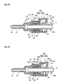
Classifications
-
- F—MECHANICAL ENGINEERING; LIGHTING; HEATING; WEAPONS; BLASTING
- F16—ENGINEERING ELEMENTS AND UNITS; GENERAL MEASURES FOR PRODUCING AND MAINTAINING EFFECTIVE FUNCTIONING OF MACHINES OR INSTALLATIONS; THERMAL INSULATION IN GENERAL
- F16L—PIPES; JOINTS OR FITTINGS FOR PIPES; SUPPORTS FOR PIPES, CABLES OR PROTECTIVE TUBING; MEANS FOR THERMAL INSULATION IN GENERAL
- F16L37/00—Couplings of the quick-acting type
- F16L37/08—Couplings of the quick-acting type in which the connection between abutting or axially overlapping ends is maintained by locking members
- F16L37/12—Couplings of the quick-acting type in which the connection between abutting or axially overlapping ends is maintained by locking members using hooks, pawls, or other movable or insertable locking members
- F16L37/14—Joints secured by inserting between mating surfaces an element, e.g. a piece of wire, a pin, a chain
- F16L37/142—Joints secured by inserting between mating surfaces an element, e.g. a piece of wire, a pin, a chain where the securing element is inserted tangentially
- F16L37/144—Joints secured by inserting between mating surfaces an element, e.g. a piece of wire, a pin, a chain where the securing element is inserted tangentially the securing element being U-shaped
-
- F—MECHANICAL ENGINEERING; LIGHTING; HEATING; WEAPONS; BLASTING
- F16—ENGINEERING ELEMENTS AND UNITS; GENERAL MEASURES FOR PRODUCING AND MAINTAINING EFFECTIVE FUNCTIONING OF MACHINES OR INSTALLATIONS; THERMAL INSULATION IN GENERAL
- F16L—PIPES; JOINTS OR FITTINGS FOR PIPES; SUPPORTS FOR PIPES, CABLES OR PROTECTIVE TUBING; MEANS FOR THERMAL INSULATION IN GENERAL
- F16L37/00—Couplings of the quick-acting type
- F16L37/08—Couplings of the quick-acting type in which the connection between abutting or axially overlapping ends is maintained by locking members
- F16L37/12—Couplings of the quick-acting type in which the connection between abutting or axially overlapping ends is maintained by locking members using hooks, pawls, or other movable or insertable locking members
- F16L37/133—Couplings of the quick-acting type in which the connection between abutting or axially overlapping ends is maintained by locking members using hooks, pawls, or other movable or insertable locking members using flexible hooks
-
- F—MECHANICAL ENGINEERING; LIGHTING; HEATING; WEAPONS; BLASTING
- F16—ENGINEERING ELEMENTS AND UNITS; GENERAL MEASURES FOR PRODUCING AND MAINTAINING EFFECTIVE FUNCTIONING OF MACHINES OR INSTALLATIONS; THERMAL INSULATION IN GENERAL
- F16L—PIPES; JOINTS OR FITTINGS FOR PIPES; SUPPORTS FOR PIPES, CABLES OR PROTECTIVE TUBING; MEANS FOR THERMAL INSULATION IN GENERAL
- F16L37/00—Couplings of the quick-acting type
- F16L37/08—Couplings of the quick-acting type in which the connection between abutting or axially overlapping ends is maintained by locking members
- F16L37/084—Couplings of the quick-acting type in which the connection between abutting or axially overlapping ends is maintained by locking members combined with automatic locking
- F16L37/088—Couplings of the quick-acting type in which the connection between abutting or axially overlapping ends is maintained by locking members combined with automatic locking by means of a split elastic ring
- F16L37/0885—Couplings of the quick-acting type in which the connection between abutting or axially overlapping ends is maintained by locking members combined with automatic locking by means of a split elastic ring with access to the split elastic ring from a radial or tangential opening in the coupling
-
- F—MECHANICAL ENGINEERING; LIGHTING; HEATING; WEAPONS; BLASTING
- F16—ENGINEERING ELEMENTS AND UNITS; GENERAL MEASURES FOR PRODUCING AND MAINTAINING EFFECTIVE FUNCTIONING OF MACHINES OR INSTALLATIONS; THERMAL INSULATION IN GENERAL
- F16L—PIPES; JOINTS OR FITTINGS FOR PIPES; SUPPORTS FOR PIPES, CABLES OR PROTECTIVE TUBING; MEANS FOR THERMAL INSULATION IN GENERAL
- F16L37/00—Couplings of the quick-acting type
- F16L37/08—Couplings of the quick-acting type in which the connection between abutting or axially overlapping ends is maintained by locking members
- F16L37/084—Couplings of the quick-acting type in which the connection between abutting or axially overlapping ends is maintained by locking members combined with automatic locking
- F16L37/098—Couplings of the quick-acting type in which the connection between abutting or axially overlapping ends is maintained by locking members combined with automatic locking by means of flexible hooks
- F16L37/0985—Couplings of the quick-acting type in which the connection between abutting or axially overlapping ends is maintained by locking members combined with automatic locking by means of flexible hooks the flexible hook extending radially inwardly from an outer part and engaging a bead, recess or the like on an inner part
-
- F—MECHANICAL ENGINEERING; LIGHTING; HEATING; WEAPONS; BLASTING
- F16—ENGINEERING ELEMENTS AND UNITS; GENERAL MEASURES FOR PRODUCING AND MAINTAINING EFFECTIVE FUNCTIONING OF MACHINES OR INSTALLATIONS; THERMAL INSULATION IN GENERAL
- F16L—PIPES; JOINTS OR FITTINGS FOR PIPES; SUPPORTS FOR PIPES, CABLES OR PROTECTIVE TUBING; MEANS FOR THERMAL INSULATION IN GENERAL
- F16L2201/00—Special arrangements for pipe couplings
- F16L2201/10—Indicators for correct coupling
-
- F—MECHANICAL ENGINEERING; LIGHTING; HEATING; WEAPONS; BLASTING
- F16—ENGINEERING ELEMENTS AND UNITS; GENERAL MEASURES FOR PRODUCING AND MAINTAINING EFFECTIVE FUNCTIONING OF MACHINES OR INSTALLATIONS; THERMAL INSULATION IN GENERAL
- F16L—PIPES; JOINTS OR FITTINGS FOR PIPES; SUPPORTS FOR PIPES, CABLES OR PROTECTIVE TUBING; MEANS FOR THERMAL INSULATION IN GENERAL
- F16L2201/00—Special arrangements for pipe couplings
- F16L2201/20—Safety or protective couplings
Definitions
- the present invention relates to a quick connector.
- Quick connectors have been disclosed, for example, in Japanese Patent Laid-Open Publication No. 2005-282762 (Patent Document 1) and Japanese Patent Laid-Open Publication No. 2007-278508 (Patent Document 2).
- the quick connectors disclosed in these patent documents include a checker confirming whether a pipe body has been surely engaged with a retainer.
- the annular projection of the pipe body may simultaneously expand diameters of both the elastically-deformable claw of the retainer and the elastically-deformable claw of the checker.
- the checker is in a slidable state.
- An object of the present invention is to provide a quick connector capable of surely confirming that the pipe body is engaged by the retainer when the elastically-deformable claw of the retainer and the elastically-deformable claw of the checker are adjacently arranged in the axial direction.
- a quick connector according to the present invention is coupled to a cylindrical pipe body having an annular projection formed projecting radially outward at a location axially spaced a predetermined distance from a distal end.
- the quick connector includes: a cylindrical housing body; a retainer integrally formed with or coupled to the housing body, having a shape capable of allowing the pipe body to be inserted therethrough in an axial direction from an opening end of the retainer, and engaging the annular projection of the pipe body inserted into the retainer from the opening end in the axial direction to regulate disengagement of the pipe body in the axial direction; and a checker confirming that the annular projection of the pipe body is in a state of being engaged by the retainer by sliding in a set radial direction with respect to the retainer to move from a first position to a second position.
- the retainer includes: a retainer body having a first engagement portion and a second engagement portion; and a retainer diameter-expanding elastically-deformable claw provided on the retainer body, having a C-shape capable of expanding diametrically by elastic deformation, allowing the annular projection of the pipe body to pass through in the axial direction by expanding diametrically, and engaging with the annular projection in the axial direction by restoring its original shape after the annular projection of the pipe body has passed through in the axial direction.
- the checker includes: a checker diameter-expanding elastically-deformable claw formed in a C-shape capable of expanding diametrically by elastic deformation, regulating sliding with respect to the retainer body from the first position toward the set radial direction by being engaged by the first engagement portion not in a diameter-expanded state, being expanded diametrically by the annular projection of the pipe body after which has passed through the retainer diameter-expanding elastically-deformable claw in the axial direction, and being slidable with respect to the retainer body from the first position toward the second position in the set radial direction by being released from the engagement with the first engagement portion in a diameter-expanded state; and a checker-axis direction elastically-deformable claw having a distal-end side formed flexibly deformable in the axial direction, maintaining a state of being engaged by the second engagement portion of the retainer body by having the deflective deformation regulated by the retainer diameter-expanding elastically-de
- the annular projection of the pipe body when the annular projection of the pipe body is located at the same axial location as the checker diameter-expanding elastically-deformable claw, the engagement with the first engagement portion of the retainer by the checker diameter-expanding elastically-deformable claw is released.
- the checker cannot slide with respect to the retainer from the first position toward the set radial direction. That is, when the checker does not slide, it is determined that the pipe body is not engaged by the retainer.
- the retainer diameter-expanding elastically-deformable claw in order for the engagement with the second engagement portion of the retainer by the checker-axis direction elastically-deformable claw to be in a releasable state, the retainer diameter-expanding elastically-deformable claw must restore its original shape. That is, in order for the checker to be in a state slidable from the first position toward the set radial direction, it is required to satisfy that (A) the checker diameter-expanding elastically-deformable claw is expanded diametrically by the annular projection of the pipe body and (B) the retainer diameter-expanding elastically-deformable claw restores its original shape.
- the checker diameter-expanding elastically-deformable claw is in the state of being engaged with the second engagement portion of the retainer, and thus the checker cannot slide from the first position toward the set radial direction. That is, it can be confirmed that it is not yet in the state in which the annular projection of the pipe body is engaged by the retainer diameter-expanding elastically-deformable claw. In the state in which the annular projection of the pipe body is engaged by the retainer diameter-expanding elastically-deformable claw, the above conditions (A) and (B) are satisfied.
- the checker can be surely slid in the set radial direction. As described above, according to the present invention, that the annular projection of the pipe body is engaged by the retainer diameter-expanding elastically-deformable claw can be surely confirmed.
- the axial direction corresponds to the axial direction of the portion of the pipe body that is inserted into the quick connector.
- the set radial direction along which the checker slides from the first position to the second position includes a case of a push-in direction of the checker with respect to the retainer and a case of a withdraw direction of the checker with respect to the retainer.
- the set radial direction is the push-in direction of the checker with respect to the retainer
- the checker does not become an unnecessary part, and thus this has an effect that waste parts can be reduced.
- the retainer includes a case where the retainer is integrally formed with the housing body and a case of a configuration in which the retainer is separately formed and is coupled to the housing body. In particular, in the case where the retainer is integrally formed with the housing body, this has an effect that the number of parts can be reduced.
- the set radial direction along which the checker slides with respect to the retainer from the first position to the second position may be the push-in direction of the checker with respect to the retainer; an opening side of the C-shape of the retainer diameter-expanding elastically-deformable claw may be a direction opposite to the push-in direction; and the checker may have a release portion diametrically expanding the retainer diameter-expanding elastically-deformable claw by sliding with respect to the retainer from the second position to a third position in the set radial direction.
- the checker is causing the retainer to perform a release operation. That is, the checker in the present invention performs the confirmation of the engagement of the pipe body and the release of the pipe body. This allows the quick connector as a whole to be simply configured without imposing complex features to the retainer.
- the quick connector may include a release regulation means regulating sliding of the checker toward the third position with respect to the retainer body in the state in which the checker is positioned at the second position with respect to the retainer body, and allowing the checker to be slidable with respect to the retainer body toward the third position when a force is applied.
- the release regulation means when the checker is positioned at the second position (engagement confirmation position), without applying a force to the release regulation means to release the regulation, the checker cannot slide to the third position (release position). Therefore, interference due to surrounding parts and accidentally sliding the checker toward the third position (release position) by an operator can be prevented.
- the retainer body or the housing body may include a third engagement portion as the release regulation means; and the checker may include a release elastically-deformable claw as the release regulation means.
- the release elastically-deformable claw regulates sliding of the checker toward the third position with respect to the retainer body by being engaged by the third engagement portion in a state in which the checker is positioned at the second position with respect to the retainer body, and allows the checker to be slidable toward the third position with respect to the retainer body by elastically deforming to release engagement with the third engagement portion.
- the release elastically-deformable claw capable of engaging the third engagement portion of the retainer body or the housing body
- the checker cannot slide to the third position (release position) unless the engagement of the release elastically-deformable claw with the third engagement portion is released. That is, by providing the third engagement portion that configures one part of the release regulation means on the retainer body or the housing body and by providing the release elastically-deformable claw that configures the other part of the release regulation means on the checker, interference due to surrounding parts and accidentally sliding the checker to the third position (release position) by an operator can be prevented without adding any new part.
- the release elastically-deformable claw may release engagement with the third engagement portion by elastically deforming in a direction different from the set radial direction along which the checker slides with respect to the retainer body.
- it is necessary to apply a force in a direction different from the direction of the push-in movement of the checker. Therefore, interference due to surrounding parts and accidentally sliding the checker to the third position (release position) by an operator can be surely prevented.
- the release elastically-deformable claw may release engagement with the third engagement portion by elastically deforming in such a way as to rotate around a support point located at a base of the release elastically-deformable claw; a site of the release elastically-deformable claw in contact with the third engagement portion may form a sloped surface with respect to the set radial direction; and the sloped surface may be formed in such a way that a rotation direction of a moment about the support point generated by an engagement force received by the release elastically-deformable claw from the third engagement portion when the checker is pushed in in the set radial direction is opposite to a rotation direction for releasing the release elastically-deformable claw from engagement with the third engagement portion.
- the release elastically-deformable claw can be prevented from being elastically deformed by the force to release the engagement with the third engagement portion. Therefore, interference due to surrounding parts and accidentally sliding the checker to the third position (release position) by an operator can be surely prevented.
- the retainer body may include an open end seat member forming the opening end of the retainer and forming the second engagement portion; and the checker may include a gap intervening member formed on a radially inner side of the checker-axis direction elastically-deformable claw with a slit intervening therebetween, intervening in an axial gap between the open end seat member of the retainer body and the retainer diameter-expanding elastically-deformable claw during a period when the checker moves from the first position to the second position with respect to the retainer.
- the gap intervening member can fill the space for the retainer diameter-expanding elastically-deformable claw to deform. Therefore, the retainer diameter-expanding elastically-deformable claw can be inhibited from deforming in the axial direction. As a result, in the state in which the annular projection of the pipe body is engaged by the retainer diameter-expanding elastically-deformable claw, a force for withdrawing the pipe body from the retainer can be increased. Further, a slit is provided between the gap intervening member and the checker-axis direction elastically-deformable claw. Therefore, regardless of whether elastic deformation of the gap intervening member is regulated, the checker-axis direction elastically-deformable claw is in an elastically-deformable state. Therefore, the above-described operation of the checker-axis direction elastically-deformable claw can be realized.
- the retainer and the checker may include a guide means regulating a relative rotation and guiding relative sliding in the set radial direction. This allows smoother sliding movement of the checker in the set radial direction.
- the checker-axis direction elastically-deformable claw may be a pair of checker-axis direction elastically-deformable claws respectively corresponding to two ends of the retainer diameter-expanding elastically-deformable claw. In this way, by providing the pair of the checker-axis direction elastically-deformable claws, the checker-axis direction elastically-deformable claws can surely perform their function.
- the retainer may be integrally formed with the housing body; and the retainer may include a stopper regulating diameter expansion of the retainer diameter-expanding elastically-deformable claw when amount of diameter expansion of the retainer diameter-expanding elastically-deformable claw has reached a set amount. This prevents the retainer diameter-expanding elastically-deformable claw from deforming more than necessary to plastically deform. Integrally forming the retainer and the housing body allows the stopper to be very easily formed.
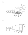
- the quick connector 1 is used, for example, for configuring a gasoline fuel piping of an automobile. That is, the quick connector 1 forms, for example, a flow path for fuel to pass through.
- One end (left side in Figs. 1 and 2 ) of the quick connector 1 is connected to a resin tube (not shown in the drawings), and the other end of the quick connector 1 is coupled to a pipe body 3 (illustrated in Fig 23 ), which is inserted into the other end of the quick connector 1. That is, the quick connector 1 provides a piping connection between the pipe body 3 and the resin tube to let gasoline fuel pass through.
- the pipe body 3 is formed in a cylindrical shape, and has an annular projection 3a (illustrated in Fig. 23 ) projecting radially outward at a location axially spaced a predetermined distance from a distal end.
- the quick connector 1 is configured to include a first housing 10, a second housing 30, a checker 50, a collar 70, and annular seal members 81 and 82.
- the first housing 10 is made of, for example, glass fiber reinforced polyamide, and is formed in a cylindrical shape forming a through passage from one axial side to the other axial side.
- the first housing 10, as illustrated in Figs 1 and 2 has a shape forming a linear through passage.
- a flow path may also be formed, for example, as a through passage in a bent shape such as an "L-shape", an "inverted V-shape", and the like.
- a tube connecting portion 11 connecting a resin tube (not shown in the drawings) is provided on one axial side (left side in Figs. 1 and 2 ) of the first housing 10.
- a pipe insertion portion 12 is provided on the other axial side (right side in Figs. 1 and 2 ) of the first housing 10, which is formed with an opening allowing the distal end of the pipe body 3 (illustrated in Fig. 23 ) to be inserted thereinto.
- An outer circumferential surface of the tube connecting portion 11 is formed in a step shape toward the axial direction for preventing the resin tube in an engaged state from being slipped off.
- a gasoline fuel flow path is formed as a through passage.
- the pipe inserting portion 12 is formed in a cylindrical shape having a diameter larger than an outer diameter of the tube connecting portion 11, and is integrally formed on the other axial side (right side in Figs. 1 and 2 ) of the tube connecting portion 11.
- the annular seal members 81 and 82 which are made of fluorine rubber
- the collar 70 which is made of resin
- the distal end of the pipe body 3 is inserted into an inner periphery side of these.
- the second housing 30 is made of, for example, glass fiber reinforced polyamide, and is formed in a nearly cylindrical shape.
- the second housing 30 is configured to include: a housing body 31 (which corresponds to a "housing body” of the present invention), which is coupled to the other axial side (right side in Figs. 1 and 2 ) of the first housing 10; and a retainer 41 (which corresponds to a "retainer” of the present invention), which engages the annular projection 3a of the pipe body 3 (illustrated in Fig. 23 ).
- the housing body 31 and the retainer 41 are integrally formed. Details of the second housing 30 will be explained later in a separate section. Therefore, an overview of the second housing 30 is explained here.
- the housing body 31 is a portion formed in a cylindrical shape, and is fitted to the other axial side (right side in Figs 1 and 2 ) of the first housing 10.
- the retainer 41 is integrally formed on the other axial side (right side in Figs 1 and 2 ) of the housing body 31.
- the retainer 41 is formed in a shape allowing the pipe body 3 (illustrated in Fig. 23 ) to be inserted therethrough from an open end portion (right end portion in Figs. 1 and 2 ) of the retainer 41. Further, the retainer 41 engages the annular projection 3a of the pipe body 3 inserted from the open end portion of the retainer 41 to regulate disengagement of the pipe body 3.
- the checker 50 is made of, for example, glass fiber reinforced polyamide, and is a member for confirming that the annular projection 3a of the pipe body 3 is in a state engaged by the retainer 41. Details of the checker 50 will be explained later in a separate section. Therefore, an overview of the checker 50 is explained here.
- the checker 50 is slid in a push-in direction (downward in Figs 1 and 20 , which corresponds to a "set radial direction" in the present invention) with respect to the retainer 41 to move from a first position (position illustrated in Figs. 20 - 22 ) with respect to the retainer 41 to a second position (position illustrated in Figs. 32-34 ).
- the sliding operation confirms that the annular projection 3a of the pipe body 3 is in a state engaged by the retainer 41. Further, by sliding the checker 50 from the second position (position illustrated in Figs. 32 - 34 ) with respect to the retainer 41 to a third position (position illustrated in Figs. 35 - 37 ) positioned in the push-in direction (downward in Figs. 1 and 20 ), the annular projection 3a of the pipe body 3 is released from the engagement with the retainer 41.
- the quick connector 1 is of a retainer-housing integrated type and of a checker-push type.
- the checker 50 of the quick connector 1 having a release feature, is of a push-release type.
- a side on which the checker 50 is mounted with respect to the retainer 41 is an upper side. That is, in the explanation, the checker 50 is slid from the upper side to the lower side with respect to the retainer 41, in engagement confirmation and push-release by the checker 50.
- the second housing 30 is configured to include the housing body 31 and the retainer 41.
- the housing body 31 and the retainer 41 are integrally formed, there is not a strict boundary therebetween.
- an axial location W in Fig. 4 is used as a boundary.
- the housing body 31 is provided as a portion W1 on the left side of the axial location W in Fig. 4 (one axial side), and the retainer 41 is provided as a portion W2 on the right side of the axial location W in Fig. 4 (other axial side).
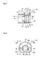
- the housing body 31 is formed in a cylindrical shape, and has a groove 32 formed over the whole circumference, which opens toward the one axial side (left side in Fig. 5 ).
- the axial length of an outer periphery cylindrical portion 33 of the groove 32 is formed longer than the axial length of an inner periphery cylindrical portion 34 of the groove 32.
- the portion of the other axial side (right side in Fig. 1 ) of the first housing 10 is fitted into the groove 32. That is, the inner periphery cylindrical portion 34 of the housing body 31 positions the collar 70 and the annular seal members 81 and 82 in the axial direction. Further, as Figs.
- a flange 35 projecting radially outward is formed at the other axial side (right side in Figs. 4 and 5 ) of the housing body 31 on the periphery excluding a bottom portion in Figs. 10 and 11 .
- the retainer 41 is integrally formed on the other axial side (right side in Figs. 4 and 5 ) of the housing body 31 and has a central hole formed for inserting the pipe body 3 therethrough.
- the retainer 41 is configured to include a retainer body 42 and a retainer diameter-expanding elastically-deformable claw 49.
- the retainer body 42 is integrally formed with the housing body 31, and is a portion that does not deform, in a sense to be distinguished from the retainer diameter-expanding elastically-deformable claw 49.
- the retainer body 42 includes an open end seat member 43, a lower joining member 44, a first engagement portion 45, a second engagement portion 46, a guide portion 47, and a stopper 48.
- the open end seat member 43 is formed having a nearly identical outer shape and axial width as the flange 35 of the housing body 31.
- the open end seat member 43 is coaxially arranged at the other axial side to face the flange 35 of the housing body 31 at a distance therefrom.
- a central hole 43a is formed having dimensions capable of allowing the annular projection 3a of the pipe body 3 to pass through.
- each of a pair of engagement holes (referred to as the "second engagement portions 46" in the following) as the second engagement portion 46 is formed on respective left and right sides of the central hole 43a in Fig. 9 .
- the pair of the second engagement portions 46 and 46 are formed as through holes in the axial direction.
- upper surfaces of the pair of the second engagement portions 46 and 46 are formed with a slope rising in a direction from the left side to the right side in Fig. 12 . While an explanation will be provided later with reference to Fig. 20 , this is for engaging distal-end projections 52a and 52b of checker-axis direction elastically-deformable claws 52 and 52 of the checker 50 in an initial state.
- a pair of upper cutouts 43b and 43b forming plane seats are respectively formed above the pair of the second engagement portions 46 and 46 on the outer periphery surface of the open end seat member 43.
- the pair of the upper cutouts 43b and 43b are for performing initial positioning of the checker-axis direction elastically-deformable claws 52 and 52 in order to achieve the initial state illustrated in Fig. 21 . Details will be described later. That is, the pair of the upper cutouts 43b and 43b are cutouts for enabling easy installation of the checker 50 with respect to the retainer 41.
- a pair of lower cutouts 43c and 43c forming plane seats are respectively formed below the pair of the second engagement portions 46 and 46 on the outer periphery surface of the open end seat member 43.
- the pair of the lower cutouts 43c and 43c are for performing positioning of the checker-axis direction elastically-deformable claws 52 and 52 in an engagement confirmation completion state as illustrated in Fig. 33 . Details will be described later.
- the lower joining member 44 is a portion joining in the axial direction the lower portion of the other axial side surface (right side surface in Fig. 5 ) of the housing body 31 and the lower portion of the open end seat member 44.
- the first engagement portion 45 is formed in a semi-circular shape opening upward.
- the first engagement portion 45 is provided above the lower joining member 44 as illustrated in Fig. 11 , on the housing body 31 side as illustrated in Fig. 5 .
- the first engagement portion 45 is provided at a location that does not interfere with the annular projection 3a of the pipe body 3 indicated by the two-dot chain line in Fig. 11 .
- Two ends of the first engagement portion 45 are formed in an acute angular shape, and the left and right sides of the first engagement portion 45 in Fig. 11 are formed as vertical planes.
- the guide portion 47 joins the upper side of the flange 35 of the housing body 31 and the upper side of the open end seat member 43.
- the guide portion 47 is provided at a location that does not interfere with the annular projection 3a of the pipe body 3 indicated by the two-dot chain line in Fig. 11 .
- a pair of stoppers 48 and 48 respectively join two lateral locations (left and right sides in Figs. 10 and 11 ) of the central hole of the flange 35 of the housing body 31 and two lateral locations of the central hole 43a of the open end seat member 43.
- the pair of the stoppers 48 and 48 are provided at locations that do not interfere with the annular projection 3a of the pipe body 3 indicated by the two-dot chain line in Fig. 11 .
- Fig. 4 illustrates, on an upper side of an axial central portion of the pair of the stoppers 48 and 48, a cutout 48a is formed.
- the cutout 48a allows diameter expansion of the retainer diameter-expanding elastically-deformable claw 49, and also has a function to regulate the diameter expansion of the retainer diameter-expanding elastically-deformable claw 49 in a case where amount of the diameter expansion has reached a set amount. Details will be described later.
- the retainer diameter-expanding elastically-deformable claw 49 is formed in a C shape opening upward.
- the retainer diameter-expanding elastically-deformable claw 49 is diametrically expandable by elastic deformation.
- the retainer diameter-expanding elastically-deformable claw 49 is provided above the lower joining member 44 as illustrated in Fig. 10 , at approximately a central region in the axial direction as illustrated in Fig. 5 . That is, the retainer diameter-expanding elastically-deformable claw 49 is provided in the axial direction between the open end seat member 43 and the first engagement portion 45.
- Fig. 10 illustrates, the retainer diameter-expanding elastically-deformable claw 49 is formed in a C shape opening upward.
- the retainer diameter-expanding elastically-deformable claw 49 is diametrically expandable by elastic deformation.
- the retainer diameter-expanding elastically-deformable claw 49 is provided above the lower joining member 44 as illustrated in Fig
- the retainer diameter-expanding elastically-deformable claw 49 is provided at a location interfering with the annular projection 3 a of the pipe body 3 indicated by the two-dot chain line in Fig. 10 .
- the retainer diameter-expanding elastically-deformable claw 49 allows the annular projection 3a of the pipe body 3 to pass therethrough by expanding diametrically.
- the retainer diameter-expanding elastically-deformable claw 49 restores its original shape, and thereby the retainer diameter-expanding elastically-deformable claw 49 functions to engage in the axial direction the annular projection 3a of the pipe body 3.
- distal-end surfaces 49a and 49b of the retainer diameter-expanding elastically-deformable claw 49 are formed sloping downward towards inner side. This is for causing the retainer diameter-expanding elastically-deformable claw 49 to expand diametrically when the distal-end surfaces 49a and 49b of the retainer diameter-expanding elastically-deformable claw 49 are pressed by release portions 55 and 55. Further, as Fig.
- end surfaces 49c and 49d on the other axial side of the distal-end side of the retainer diameter-expanding elastically-deformable claw 49 are formed into a slope shape tapering from the other axial side (pipe body 3 insertion side) to the one axial side (resin tube connection side).
- the retainer diameter-expanding elastically-deformable claw 49 not in the diameter-expanded state interferes with the annular projection 3a of the pipe body 3.
- the checker 50 is a member for confirming that the annular projection 3 a of the pipe body 3 is in the state engaged by the retainer 41.
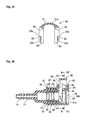
- the checker 50 is configured to include a checker diameter-expanding elastically-deformable claw 51, a checker-axis direction elastically-deformable claw 52, a gap intervening member 53, a guide portion 54, and a release portion 55.
- the checker diameter-expanding elastically-deformable claw 51 is formed in a C-shape capable of expanding diametrically by elastic deformation.
- projections 5 1 a and 51b are formed projecting toward the inner side. While details will be explained later, by being engaged by the first engagement portion 45 not in a diameter-expanded state, the checker diameter-expanding elastically-deformable claw 51 is regulated from sliding with respect to the retainer body 42 from the first position (position illustrated in Figs. 20 - 22 ) toward a downward direction (set radial direction).
- the checker diameter-expanding elastically-deformable claw 51 is expanded diametrically by the annular projection 3a of the pipe body 3 that has passed through the retainer diameter-expanding elastically-deformable claw 49.
- the checker diameter-expanding elastically-deformable claw 51 is released from the engagement with the first engagement portion 45 and is in a state capable of sliding with respect to the retainer body 42 from the first position (position illustrated in Figs. 20 - 22 ) toward the second position (position illustrated in Figs. 32 - 34 ) in the downward direction (set radial direction).
- the pair of the checker-axis direction elastically-deformable claws 52 and 52 are provided on a base portion 51c of the checker diameter-expanding elastically-deformable claw 51.
- the pair of the checker-axis direction elastically-deformable claws 52 and 52 are provided spaced a distance away from the checker diameter-expanding elastically-deformable claw 51 in the left-right direction in Fig. 13 .
- Distal-end sides of the checker-axis direction elastically-deformable claws 52 and 52 are formed capable of flexibly deforming in the left-right direction in Fig. 13 (corresponding to the axial direction in Fig. 1 ).
- projections 52a and 52b are formed projecting toward the right side in Fig. 13 .
- the checker-axis direction elastically-deformable claws 52 and 52 maintain a state of being engaged by the second engagement portion 46 of the retainer body 42 by having deflective deformation being regulated by the retainer diameter-expanding elastically-deformable claw 49. Further, by being engaged by the second engagement portion 46 of the retainer body 42, the checker-axis direction elastically-deformable claws 52 and 52 are regulated from sliding with respect to the retainer body 42 from the first position (position illustrated in Figs. 20 - 22 ) toward the downward direction (set radial direction).
- the checker-axis direction elastically-deformable claws 52 and 52 are in a state of capable of being released from engagement with the second engagement portion 46 of the retainer body 42, and thereby are in a state capable of sliding with respect to the retainer body 42 from the first position (position illustrated in Figs. 20 - 22 ) toward the second position (position illustrated in Figs. 32 - 34 ) in the downward direction (set radial direction).
- the pair of the gap intervening members 53 and 53 are respectively formed on the radially inner side of the checker-axis direction elastically-deformable claws 52 and 52 with slits 53a and 53b intervening therebetween. While details will be explained later, the pair of the gap intervening members 53 and 53 intervene in the axial gaps between the open end seat member 43 of the retainer body 42 and the retainer diameter-expanding elastically-deformable claw 49 during a period when the checker 50 moves with respect to the retainer 41 from the first position (position illustrated in Figs. 20 - 22 ) to the second position (position illustrated in Figs. 32 - 34 ).
- the guide portions 54 and 54 are provided on the base portion 51c of the checker diameter-expanding elastically-deformable claw 51, and are formed on the inner side of the C-shape of the checker diameter-expanding elastically-deformable claw 51. These guide portions 54 and 54 are formed spaced at a distance corresponding to the width of the guide portion 47 of the retainer 41. By engaging with the guide portion 47 of the retainer 41, the guide portions 54 and 54 of the checker 50 regulate relative rotation between the retainer 41 and the checker 50, and have a function of guiding the relative sliding movement in the up-down direction.
- the release portions 55 and 55 are provided on the base portion 51c of the checker diameter-expanding elastically-deformable claw 51, and are formed in the axial direction between the checker-axis direction elastically-deformable claw 52 and the guide portion 54.
- the release portions 55 and 55 are formed inclining from the inner side towards the outer side.
- the release portions 55 and 55 are formed in a shape corresponding to the slope shape of the distal-end surfaces 49a and 49b of the retainer diameter-expanding elastically-deformable claw 49. While details will be explained later, when the checker 50 slides with respect to the retainer 41 from the second position (position illustrated in Figs.
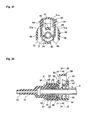
- the initial state is a state in which the checker 50 is positioned at the first position with respect to the retainer 41.
- the checker 50 is installed from above the retainer 41.
- the "above the retainer 41" corresponds to the opening side of the retainer diameter-expanding elastically-deformable claw 49.
- the distal-end side of the checker diameter-expanding elastically-deformable claw 51 is inserted into the axial gap between the flange 35 of the housing body 31 and the retainer diameter-expanding elastically-deformable claw 49.
- the distal end of the first engagement portion 45 of the retainer 41 is positioned further beyond the distal ends (lower side in Fig. 21 ) of the distal-end projections 51a and 51b of the checker diameter-expanding elastically-deformable claw 51. Therefore, the checker diameter-expanding elastically-deformable claw 51 is regulated from sliding further downward.
- Figs. 20 and 21 illustrate, in the initial state, the gap intervening members 53 and 53 are inserted in the axial gaps between the open end seat member 43 of the retainer 41 and the retainer diameter-expanding elastically-deformable claw 49.
- the distal-end projections 52a and 52b of the checker-axis direction elastically-deformable claws 52 and 52 are in a state of having entered into the second engagement portions 46 and 46 of the open end seat member 43 of the retainer 41.
- the checker 50 can be prevented from disengaging from the retainer 41.
- the engagement involves acute angles, and is thus more effective.
- a first intermediate state which is a state in which a portion of the distal end of the pipe body 3 has been inserted from the open end seat member 43 side of the quick connector 1, is explained with reference to Figs. 23 - 25 .
- the pipe body 3 is formed in a cylindrical shape, and has the annular projection 3a (illustrated in Fig. 23 ) formed projecting radially outward at a location axially spaced a predetermined distance from the distal end.
- the annular projection 3a interferes with the retainer diameter-expanding elastically-deformable claw 49. Therefore, as Fig.
- the annular projection 3a of the pipe body 3 causes the retainer diameter-expanding elastically-deformable claw 49 to elastically deform to expand diametrically.
- the annular projection 3a of the pipe body 3 presses against the end surfaces 49c and 49d on the other axial side on the distal-end side of the retainer diameter-expanding elastically-deformable claw 49. Therefore, the retainer diameter-expanding elastically-deformable claw 49 relatively easily expands diametrically.
- the checker diameter-expanding elastically-deformable claw 51 is positioned on the one axial side (insertion direction of the pipe body 3) of the retainer diameter-expanding elastically-deformable claw 49. Therefore, although the retainer diameter-expanding elastically-deformable claw 49 is axially pressed against by the annular projection 3a of the pipe body 3, the retainer diameter-expanding elastically-deformable claw 49 is inhibited from being axially deformed by the checker diameter-expanding elastically-deformable claw 51. This also allows the retainer diameter-expanding elastically-deformable claw 49 to relative easily expand diametrically.
- Fig. 24 illustrates, by diametrically expanding the retainer diameter-expanding elastically-deformable claw 49, the annular projection 3a of the pipe body 3 can pass through the location of the retainer diameter-expanding elastically-deformable claw 49.
- the stoppers 48 and 48 are formed in the retainer 41.
- the stoppers 48 and 48 regulate the amount of the diameter expansion so as to not exceed a set amount. Therefore, when in contact with the stoppers 48 and 48, the retainer diameter-expanding elastically-deformable claw 49 stops further expanding diametrically.
- Fig. 25 illustrates, when the retainer diameter-expanding elastically-deformable claw 49 performs the above operation, the checker diameter-expanding elastically-deformable claw 51 does not expand diametrically. That is, the distal-end projections 51a and 51b of the checker diameter-expanding elastically-deformable claw 51 are regulated from sliding downward by the first engagement portion 45 of the retainer 41.
- the pair of the checker-axis direction elastically-deformable claws 52 and 52 are in a state of being sandwiched between the retainer diameter-expanding elastically-deformable claw 49 in a diameter-expanded state and the open end seat member 43. That is, the checker-axis direction elastically-deformable claws 52 and 52 are in a state of being regulated from flexibly deforming in the axial direction.
- the checker-axis direction elastically-deformable claws 52 and 52 in order for the checker-axis direction elastically-deformable claws 52 and 52 to be disengaged from the second engagement portion 46 of the retainer 41, the checker-axis direction elastically-deformable claws 52 and 52 must flexibly deform in the axial direction.
- the checker-axis direction elastically-deformable claws 52 and 52 are in the state of being regulated from flexibly deforming in the axial direction. Therefore, the checker-axis direction elastically-deformable claws 52 and 52 are also regulated from sliding downward with respect to the retainer 41.
- the checker diameter-expanding elastically-deformable claw 51 is arranged in the axial direction adjacent to the retainer diameter-expanding elastically-deformable claw 49. Therefore, a situation may occur in which the annular projection 3a of the pipe body 3 expands diameters of both the retainer diameter-expanding elastically-deformable claw 49 and the checker diameter-expanding elastically-deformable claw 51.
- Fig. 28 illustrates, as a second intermediate state to be explained later, the checker diameter-expanding elastically-deformable claw 51 expands diametrically.
- the distal-end projections 51a and 51b of the checker diameter-expanding elastically-deformable claw 51 disengage from the location of the first engagement portion 45 of the retainer 41. That is, the checker diameter-expanding elastically-deformable claw 51 is in a state capable of sliding downward without being engaged by the first engagement portion 45.
- a second intermediate state which is a state in which a portion of the distal end of the pipe body 3 has been further inserted, will be explained with reference to Figs. 26 - 28 .
- Fig. 26 illustrates, the annular projection 3a of the pipe body 3 passes through the location of the retainer diameter-expanding elastically-deformable claw 49.
- Fig. 27 illustrates, the retainer diameter-expanding elastically-deformable claw 49 restores its original shape, and thereby the retainer diameter-expanding elastically-deformable claw 49 engages in the axial direction the annular projection 3a of the pipe body 3.
- the checker-axis direction elastically-deformable claws 52 and 52 are in a state capable of flexibly deforming in the axial direction.
- Fig. 27 illustrates, this is because the retainer diameter-expanding elastically-deformable claw 49 has restored its original shape, and thus is not positioned at a position sandwiching the checker-axis direction elastically-deformable claws 52 and 52. Then, the checker diameter-expanding elastically-deformable claw 51 and the checker-axis direction elastically-deformable claws 52 and 52 together are in a state capable of sliding in the downward direction (set radial direction).
- the checker 50 is in the state capable of sliding toward the downward direction (set radial direction) with respect to the retainer 41 only after the retainer diameter-expanding elastically-deformable claw 49 is in the state surely engaged with the annular projection 3a of the pipe body 3.
- the third intermediate state is a state in which the checker 50 is positioned in the middle between the first position and the second position.
- the third intermediate state is explained with reference to Figs. 29 - 31 .
- Fig. 29 in order for the state of the checker-axis direction elastically-deformable claws 52 and 52 to be easily understood, only an outer shape of the pipe body 3 is illustrated using a two-dot chain line.
- Figs. 29 and 30 illustrate, distal-end sides of the checker-axis direction elastically-deformable claws 52 and 52 are flexibly deformed.
- Fig. 31 illustrates, the checker diameter-expanding elastically-deformable claw 51 slides downward along lateral sides of the first engagement portion 45 of the retainer 41.
- the guide portion 47 of the retainer 41 and the guide portions 54 and 54 of the checker 50 regulate a relative rotation so as to guide the relative sliding movement in the push-in direction. This allows smoother sliding movement of the checker 50 in the push-in direction with respect to the retainer 41.
- the checker diameter-expanding elastically-deformable claw 51 restores its original shape, and engages the lower surface of the distal-end side of the first engagement portion 45 of the retainer 41. That is, the checker diameter-expanding elastically-deformable claw 51 is regulated from sliding in a returning direction (upward direction) by being engaged by the first engagement portion 45.
- Figs. 32 and 33 illustrate, the checker-axis direction elastically-deformable claws 52 and 52 are engaged by the lower cutouts 43c and 43c of the open end seat member 43 of the retainer 41. That is, the checker-axis direction elastically-deformable claws 52 and 52 are regulated from sliding in the returning direction (upward direction) by being engaged by the open end seat member 43.
- the distal-end surfaces 49a and 49b of the retainer diameter-expanding elastically-deformable claw 49 are positioned below the release portions 55 and 55 of the checker 50. Therefore, in order for the checker 50 to further slide downward, the retainer diameter-expanding elastically-deformable claw 49 must be expanded diametrically. In order to diametrically expand the retainer diameter-expanding elastically-deformable claw 49, the checker 50 must be further pushed in. That is, when the checker 50 arrives at the second position, the checker 50 is in a state without being acted upon by any force, and is in an upwardly and downwardly engaged state with respect to the retainer 41.
- the operator can recognize that the pipe body 3 is in a state surely coupled to the quick connector 1.
- the pipe body 3 is in a state of being surely coupled to the quick connector 1.
- the gap intervening members 53 and 53 have a function to fill the axial gaps between the retainer diameter-expanding elastically-deformable claw 49 and the open end seat member 43. This allows axial deformation of the retainer diameter-expanding elastically-deformable claw 49 to be inhibited.
- the force for withdrawing the pipe body 3 from the retainer 41 can be increased.
- the slits 53a and 53b are provided between the gap intervening members 53 and 53 and the checker-axis direction elastically-deformable claws 52 and 52. Therefore, regardless of whether the elastic deformation of the gap intervening members 53 and 53 is regulated, the checker-axis direction elastically-deformable claws 52 and 52 are in an elastically-deformable state. Therefore, the above-described operation of the checker-axis direction elastically-deformable claws 52 and 52 can be realized.
- a case may occur in which the pipe body 3 is withdrawn (released) from the quick connector 1, such as for maintenance and the like.
- This case is explained with reference to Figs. 35 - 37 .
- the checker 50 is slid from the second position with respect to the retainer 41 further in the push-in direction (downward).
- the release portions 55 and 55 of the checker 50 diametrically expand the retainer diameter-expanding elastically-deformable claw 49. That is, to release, a force large enough to be able to diametrically expand the retainer diameter-expanding elastically-deformable claw 49 is required to push in the checker 50.
- the release portions 55 and 55 of the checker 50 are formed in a shape corresponding to the slope shape of the distal-end surfaces 49a and 49b of the retainer diameter-expanding elastically-deformable 49. Therefore, by pushing the checker 50 into the retainer 41, the diameter of the retainer diameter-expanding elastically-deformable claw 49 can be expanded relatively easily. However, it is preferable that the force be larger than the force required for pushing in the checker 50 during engagement confirmation. This allows a release state to be prevented from occurring during engagement confirmation.
- the checker 50 can cause the retainer 41 to perform the release operation.
- the checker 50 performs engagement confirmation of the pipe body 3 and release of the pipe body 3. This allows the quick connector 1 as a whole to be simply configured without imposing complex features to the retainer 41.
- the quick connector according to the second embodiment has a second housing and a checker that are different from the quick connector according to the first embodiment. Further, an engagement confirmation state and transition from the engagement confirmation state to a release state are different from the first embodiment. In the following, the differences are explained. Incidentally, elements that are the same as in the first embodiment are denoted by the same reference numerals, and the explanation thereof is omitted.
- the detailed configuration of a second housing 130 will be explained with reference to Figs. 38 - 46 .
- the second housing 130 is configured to include a housing body 131 and a retainer 141. Since the housing body 131 and the retainer 141 are integrally formed, there is not a strict boundary. However, in the explanation here, an axial location W in Fig. 38 is used as a boundary.
- the housing body 131 is provided as a portion W1 on a left side (one axial side) of the axial location W in Fig. 38 and the retainer 141 is provided as a portion W2 on a right side (other axial side) of the axial location W in Fig. 38 .
- the housing body 131 is different from the housing body 31 according to the first embodiment in that a third engagement portion 136 is formed at a place of the flange 35 where a cutout is formed at an upper portion in Figs. 44 and 45 .
- the third engagement portion 136 is formed projecting upward in the drawing forming a shape of an acute angle. That is, a normal direction of an inclined surface of the third engagement portion 136 on the right side in Fig. 39 is a direction combining a component (upward direction component in Fig. 39 ) of a direction opposite to the push-in direction of a checker 150 and a component (rightward direction component in Fig.
- a normal direction of an inclined surface of the third engagement portion 136 on the left side in Fig. 39 is a direction combining a component (upward direction component in Fig. 39 ) of the direction opposite to the push-in direction of the checker 150 and a component (leftward direction component in Fig. 39 ) of the axial direction on the opposite side of the retainer 141 side.
- the joining portion 147 joins a portion slightly below the third engagement portion 136 of the flange 35 of the housing body 131 and the upper side of the open end seat member 43.
- the joining portion 147 is provided at a location that does not interfere with the annular projection 3a of the pipe body 3 indicated by the two-dot chain line in Fig. 45 .
- each of the guide portions 148b is formed along the outer periphery of the flange 35. Opposing sides of the pair of the guide portions 148b guide lateral sides of a checker diameter-expanding elastically-deformable claw 151 of the checker 150, which will be described later.
- the checker 150 is different from the checker 50 according to the first embodiment mainly in that a release elastically-deformable claw 156 is provided and in that the guide portion 54 is eliminated.
- the checker 150 in configured to include a checker diameter-expanding elastically-deformable claw 151, the checker-axis direction elastically-deformable claw 52, the gap intervening member 53, the release portion 55, and the release elastically-deformable claw 156.
- a base portion 151c of the checker diameter-expanding elastically-deformable claw 151 is formed eliminating portions protruding toward the left and right sides in Fig. 49 .
- the release elastically-deformable claw 156 includes a pair of arm portions 156a forming a U-shaped axial cross-sectional shape from the base portion 151c to the housing body 131 side.
- the opening side of the U-shape of the arm portions 156a is the upper side in Fig. 52 . That is, when the pair of the arm portions 156a are acted by an axial force from the housing body 131 side, the portion on the housing body 131 side elastically deforms in a direction of rotation (clockwise in Fig.
- a surface of the pair of arm portions 156a on the housing body 131 side is a sloped surface, and a normal direction of the sloped surface is a direction combining a component (downward direction component in Fig. 52 ) of the push-in direction of the checker 150 and a component (leftward direction component in Fig. 39 ) of the axial direction on the housing body 131 side.
- a claw portion 156b is integrally formed on the distal-end side of the pair of the arm portions 156a. That is, the claw portion 156b connects the pair of arm portions 156a. Therefore, when a force is applied to the claw portion 156b in the rightward direction in Fig. 52 , along with the elastic deformation in the direction of rotation of the pair of the arm portions 156a, the claw portion 156b moves toward upper-right side in Fig. 52 .
- a surface of the claw portion 156b on the pair of arm portions 156a side is a sloped surface, and a normal direction of the sloped surface is a direction combining a component (downward direction component in Fig. 52 ) of the push-in direction of the checker 150 and a component (rightward direction component in Fig. 39 ) of the axial direction on the opposite side of the housing body 131. That is, the sloped surface of the pair of the arm portions 156a and the sloped surface of the claw portion 156b form an inner surface in a shape of an acute angle.
- Fig. 53 This corresponds to the state illustrated by Figs. 32 - 35 in the first embodiment.
- the claw portion 156b of the release elastically-deformable claw 156 engages the third engagement portion 136 in the push-in direction of the checker 150. That is, in the state in which the checker 150 is positioned at the second position, the release elastically-deformable claw 156 and the third engagement portion 136 regulate the checker 150 from sliding toward the third position (position further in the push-in direction).
- the checker 150 is further slid with respect to the retainer 141 in the push-in direction (downward).
- the release portions 55 and 55 of the checker 150 expand the diameter of the retainer diameter-expanding elastically-deformable claw 49.
- the engagement with the annular projection 3a of the pipe body 3 in the axial direction is released, so that the pipe body 3 can be withdrawn from the quick connector 1.
- the pipe body 3 when an operator accidentally applied a force pushing in the checker 50 from the second position further in the push-in direction (downward), the pipe body 3 may be put in the release state.
- Fig. 53 illustrates, in the engagement confirmation position, the release elastically-deformable claw 156 engages with the third engagement portion 136.
- the checker 150 cannot slide to the third position (release position). That is, interference due to surrounding parts and accidentally sliding the checker 150 to the third position (release position) by an operator can be prevented.
- the third engagement portion 136 is provided on the housing body 131, and the release elastically-deformable claw 156 is provided on the checker 150. Thereby, the above effect can be achieved without adding new components.
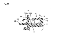
- FIG. 55 illustrates, the site of the release elastically-deformable claw 156 that is in contact with the third engagement portion 136 is in a planar shape inclined with respect to the push-in direction of the checker 150. Therefore, in the state illustrated in Fig. 55 , when a force Fa in the push-in direction (downward) is applied to the checker 150, an engagement force that the release elastically-deformable claw 156 receives from the third engagement portion 136 is Fb.
- the support point of the elastic deformation of the pair of the arm portions 156a of the release elastically-deformable claw 156 is X. Then, a moment generated by the engagement force Fb on the pair of arm portions 156a is Mb.
- Fig. 53 illustrates, in the state in which the release elastically-deformable claw 156 engages with the third engagement portion 136, even when a force is applied to push the checker 150 further in the push-in direction (downward), the release elastically-deformable claw 156 can be prevented from elastically deforming in such a way as to be released from the engagement with the third engagement portion 136. Therefore, interference due to surrounding parts and accidentally sliding the checker 150 to the third position (release position) by an operator can be surely prevented.
Landscapes
- Engineering & Computer Science (AREA)
- General Engineering & Computer Science (AREA)
- Mechanical Engineering (AREA)
- Quick-Acting Or Multi-Walled Pipe Joints (AREA)
Abstract
Description
- The present invention relates to a quick connector.
- Quick connectors have been disclosed, for example, in Japanese Patent Laid-Open Publication No.
2005-282762 2007-278508 - Operation up to when the checker confirms the engagement is as follows. When the pipe body is inserted through the retainer, an elastically-deformable claw of the retainer is expanded diametrically by an annular projection of the pipe body. Thereafter, when the annular projection of the pipe body passes through a location of the elastically-deformable claw of the retainer, the elastically-deformable claw restores its original shape, and the annular projection of the pipe body engages with the elastically-deformable claw of the retainer. On the other hand, an elastically-deformable claw of the checker is expanded diametrically by the annular projection of the pipe body that has passed through the location of the elastically-deformable claw of the retainer. The diameter expansion of the elastically-deformable claw of the checker allows the checker to become slidable. Then, by sliding the checker, it can be determined that the pipe body has been surely engaged with the retainer.
-
- [Patent Document 1] Japanese Patent Laid-Open Publication No.
2005-282762 - [Patent Document 2] Japanese Patent Laid-Open Publication No.
2007-278508 - When the elastically-deformable claw of the retainer and the elastically-deformable claw of the checker are adjacently arranged in an axial direction, the annular projection of the pipe body may simultaneously expand diameters of both the elastically-deformable claw of the retainer and the elastically-deformable claw of the checker. When such an operation is performed, despite that the pipe body is not surely engaged by the retainer, the checker is in a slidable state. This problem may be solved by adjusting dimensions of each component and manufacturing with high precision. However, there is a problem that, along with miniaturization, higher precision is required in manufacturing. Further, the higher the manufacturing precision is, the higher the cost is.
- The present invention is provided in view of such circumstances. An object of the present invention is to provide a quick connector capable of surely confirming that the pipe body is engaged by the retainer when the elastically-deformable claw of the retainer and the elastically-deformable claw of the checker are adjacently arranged in the axial direction.
- A quick connector according to the present invention is coupled to a cylindrical pipe body having an annular projection formed projecting radially outward at a location axially spaced a predetermined distance from a distal end. The quick connector includes: a cylindrical housing body; a retainer integrally formed with or coupled to the housing body, having a shape capable of allowing the pipe body to be inserted therethrough in an axial direction from an opening end of the retainer, and engaging the annular projection of the pipe body inserted into the retainer from the opening end in the axial direction to regulate disengagement of the pipe body in the axial direction; and a checker confirming that the annular projection of the pipe body is in a state of being engaged by the retainer by sliding in a set radial direction with respect to the retainer to move from a first position to a second position.
- The retainer includes: a retainer body having a first engagement portion and a second engagement portion; and a retainer diameter-expanding elastically-deformable claw provided on the retainer body, having a C-shape capable of expanding diametrically by elastic deformation, allowing the annular projection of the pipe body to pass through in the axial direction by expanding diametrically, and engaging with the annular projection in the axial direction by restoring its original shape after the annular projection of the pipe body has passed through in the axial direction.
- The checker includes: a checker diameter-expanding elastically-deformable claw formed in a C-shape capable of expanding diametrically by elastic deformation, regulating sliding with respect to the retainer body from the first position toward the set radial direction by being engaged by the first engagement portion not in a diameter-expanded state, being expanded diametrically by the annular projection of the pipe body after which has passed through the retainer diameter-expanding elastically-deformable claw in the axial direction, and being slidable with respect to the retainer body from the first position toward the second position in the set radial direction by being released from the engagement with the first engagement portion in a diameter-expanded state; and a checker-axis direction elastically-deformable claw having a distal-end side formed flexibly deformable in the axial direction, maintaining a state of being engaged by the second engagement portion of the retainer body by having the deflective deformation regulated by the retainer diameter-expanding elastically-deformable claw in a state in which the retainer diameter-expanding elastically-deformable claw is expanded diametrically, regulating sliding with respect to the retainer body from the first position toward the set radial direction by being engaged by the second engagement portion of the retainer body, and being slidable with respect to the retainer body from the first position to the second position in the set radial direction by being capable of being released from the engagement with the second engagement portion of the retainer body in a state in which the retainer diameter-expanding elastically-deformable claw has restored its original shape.
- In the present invention, when the annular projection of the pipe body is located at the same axial location as the checker diameter-expanding elastically-deformable claw, the engagement with the first engagement portion of the retainer by the checker diameter-expanding elastically-deformable claw is released. However, even when the engagement with the first engagement of the retainer by the checker diameter-expanding elastically-deformable claw is released, unless the engagement with the second engagement portion of the retainer by the checker-axis direction elastically-deformable claw is in a releasable state, the checker cannot slide with respect to the retainer from the first position toward the set radial direction. That is, when the checker does not slide, it is determined that the pipe body is not engaged by the retainer.
- In the present invention, in order for the engagement with the second engagement portion of the retainer by the checker-axis direction elastically-deformable claw to be in a releasable state, the retainer diameter-expanding elastically-deformable claw must restore its original shape. That is, in order for the checker to be in a state slidable from the first position toward the set radial direction, it is required to satisfy that (A) the checker diameter-expanding elastically-deformable claw is expanded diametrically by the annular projection of the pipe body and (B) the retainer diameter-expanding elastically-deformable claw restores its original shape.
- Here, when the checker diameter-expanding elastically-deformable claw and the retainer diameter-expanding elastically-deformable claw are adjacent to each other in the axial direction, depending on design dimensions, it is possible that the annular projection of the pipe body simultaneously expands diameters of both the checker diameter-expanding elastically-deformable claw and the retainer diameter-expanding elastically-deformable claw. In this case, it is not yet in a state in which the annular projection of the pipe body is engaged by the retainer diameter-expanding elastically-deformable claw. In this case, the above (A) is satisfied, but the above (B) is not satisfied. Therefore, even when the situation as described above occurs in which both the diameter expansion elastically-deformable claws are expanded diametrically, the checker diameter-expanding elastically-deformable claw is in the state of being engaged with the second engagement portion of the retainer, and thus the checker cannot slide from the first position toward the set radial direction. That is, it can be confirmed that it is not yet in the state in which the annular projection of the pipe body is engaged by the retainer diameter-expanding elastically-deformable claw. In the state in which the annular projection of the pipe body is engaged by the retainer diameter-expanding elastically-deformable claw, the above conditions (A) and (B) are satisfied. Therefore, in the state in which the annular projection of the pipe body is engaged by the retainer diameter-expanding elastically-deformable claw, the checker can be surely slid in the set radial direction. As described above, according to the present invention, that the annular projection of the pipe body is engaged by the retainer diameter-expanding elastically-deformable claw can be surely confirmed.
- Here, the axial direction corresponds to the axial direction of the portion of the pipe body that is inserted into the quick connector. The set radial direction along which the checker slides from the first position to the second position includes a case of a push-in direction of the checker with respect to the retainer and a case of a withdraw direction of the checker with respect to the retainer. In particular, in the case where the set radial direction is the push-in direction of the checker with respect to the retainer, the checker does not become an unnecessary part, and thus this has an effect that waste parts can be reduced. The retainer includes a case where the retainer is integrally formed with the housing body and a case of a configuration in which the retainer is separately formed and is coupled to the housing body. In particular, in the case where the retainer is integrally formed with the housing body, this has an effect that the number of parts can be reduced.
- Further, in the present invention, the set radial direction along which the checker slides with respect to the retainer from the first position to the second position may be the push-in direction of the checker with respect to the retainer; an opening side of the C-shape of the retainer diameter-expanding elastically-deformable claw may be a direction opposite to the push-in direction; and the checker may have a release portion diametrically expanding the retainer diameter-expanding elastically-deformable claw by sliding with respect to the retainer from the second position to a third position in the set radial direction.
- That is, by sliding the checker with respect to the retainer in the push-in direction, that the pipe body is engaged by the retainer can be confirmed. Then, further pushing in the checker from the second position leads to a state in which the pipe body can be withdrawn from the retainer. As just described, the checker is causing the retainer to perform a release operation. That is, the checker in the present invention performs the confirmation of the engagement of the pipe body and the release of the pipe body. This allows the quick connector as a whole to be simply configured without imposing complex features to the retainer.
- Further, in the present invention, the quick connector may include a release regulation means regulating sliding of the checker toward the third position with respect to the retainer body in the state in which the checker is positioned at the second position with respect to the retainer body, and allowing the checker to be slidable with respect to the retainer body toward the third position when a force is applied.
- As described above, in a configuration in which the checker performs the release of the pipe body by being slid with respect to the retainer further in the push-in direction from a position (the second position) for confirming the engagement of the pipe body by the checker, it is possible that the pipe body is put in a release state by interference due to surrounding parts and by accidentally over-pushing the checker by an operator.
- However, by including the release regulation means, when the checker is positioned at the second position (engagement confirmation position), without applying a force to the release regulation means to release the regulation, the checker cannot slide to the third position (release position). Therefore, interference due to surrounding parts and accidentally sliding the checker toward the third position (release position) by an operator can be prevented.
- Further, in the present invention, the retainer body or the housing body may include a third engagement portion as the release regulation means; and the checker may include a release elastically-deformable claw as the release regulation means. The release elastically-deformable claw regulates sliding of the checker toward the third position with respect to the retainer body by being engaged by the third engagement portion in a state in which the checker is positioned at the second position with respect to the retainer body, and allows the checker to be slidable toward the third position with respect to the retainer body by elastically deforming to release engagement with the third engagement portion.
- In this case, by including the release elastically-deformable claw capable of engaging the third engagement portion of the retainer body or the housing body, when the checker is positioned at the second position (engagement confirmation position), , the checker cannot slide to the third position (release position) unless the engagement of the release elastically-deformable claw with the third engagement portion is released. That is, by providing the third engagement portion that configures one part of the release regulation means on the retainer body or the housing body and by providing the release elastically-deformable claw that configures the other part of the release regulation means on the checker, interference due to surrounding parts and accidentally sliding the checker to the third position (release position) by an operator can be prevented without adding any new part.
- Further, in the present invention, the release elastically-deformable claw may release engagement with the third engagement portion by elastically deforming in a direction different from the set radial direction along which the checker slides with respect to the retainer body. In this case, in order to perform release, it is necessary to apply a force in a direction different from the direction of the push-in movement of the checker. Therefore, interference due to surrounding parts and accidentally sliding the checker to the third position (release position) by an operator can be surely prevented.
- Further, in the present invention, the release elastically-deformable claw may release engagement with the third engagement portion by elastically deforming in such a way as to rotate around a support point located at a base of the release elastically-deformable claw; a site of the release elastically-deformable claw in contact with the third engagement portion may form a sloped surface with respect to the set radial direction; and the sloped surface may be formed in such a way that a rotation direction of a moment about the support point generated by an engagement force received by the release elastically-deformable claw from the third engagement portion when the checker is pushed in in the set radial direction is opposite to a rotation direction for releasing the release elastically-deformable claw from engagement with the third engagement portion.
- Even when a force is applied to the checker to push in the checker from the second position further toward the third position, the release elastically-deformable claw can be prevented from being elastically deformed by the force to release the engagement with the third engagement portion. Therefore, interference due to surrounding parts and accidentally sliding the checker to the third position (release position) by an operator can be surely prevented.
- Further, in the present invention, the retainer body may include an open end seat member forming the opening end of the retainer and forming the second engagement portion; and the checker may include a gap intervening member formed on a radially inner side of the checker-axis direction elastically-deformable claw with a slit intervening therebetween, intervening in an axial gap between the open end seat member of the retainer body and the retainer diameter-expanding elastically-deformable claw during a period when the checker moves from the first position to the second position with respect to the retainer.
- The gap intervening member can fill the space for the retainer diameter-expanding elastically-deformable claw to deform. Therefore, the retainer diameter-expanding elastically-deformable claw can be inhibited from deforming in the axial direction. As a result, in the state in which the annular projection of the pipe body is engaged by the retainer diameter-expanding elastically-deformable claw, a force for withdrawing the pipe body from the retainer can be increased. Further, a slit is provided between the gap intervening member and the checker-axis direction elastically-deformable claw. Therefore, regardless of whether elastic deformation of the gap intervening member is regulated, the checker-axis direction elastically-deformable claw is in an elastically-deformable state. Therefore, the above-described operation of the checker-axis direction elastically-deformable claw can be realized.
- Further, in the present invention, the retainer and the checker may include a guide means regulating a relative rotation and guiding relative sliding in the set radial direction. This allows smoother sliding movement of the checker in the set radial direction.
- Further, in the present invention, the checker-axis direction elastically-deformable claw may be a pair of checker-axis direction elastically-deformable claws respectively corresponding to two ends of the retainer diameter-expanding elastically-deformable claw. In this way, by providing the pair of the checker-axis direction elastically-deformable claws, the checker-axis direction elastically-deformable claws can surely perform their function.
- Further, in the present invention, the retainer may be integrally formed with the housing body; and the retainer may include a stopper regulating diameter expansion of the retainer diameter-expanding elastically-deformable claw when amount of diameter expansion of the retainer diameter-expanding elastically-deformable claw has reached a set amount. This prevents the retainer diameter-expanding elastically-deformable claw from deforming more than necessary to plastically deform. Integrally forming the retainer and the housing body allows the stopper to be very easily formed.
-
-
Fig. 1 is a front view (diagram viewed from a direction perpendicular to an axis) of a quick connector according to a first embodiment, in which a portion is illustrated as a cross-section view. -
Fig. 2 is diagram (plain view) viewed from above inFig. 1 . -
Fig. 3 is a diagram viewed from right inFig. 1 (diagram viewed from an axial direction). -
Fig. 4 is a front view (diagram viewed from a direction perpendicular to the axis) of a second housing configuring the quick connector inFig. 1 . -
Fig. 5 is an axial cross-section view of the second housing. -
Fig. 6 is a right side view inFig. 4 . -
Fig. 7 is a left side view inFig. 4 . -
Fig. 8 is diagram (plain view) viewed from above inFig. 6 . -
Fig. 9 is a cross-section view along a line A-A inFig. 5 . -
Fig. 10 is a cross-section view along a line B-B inFig. 5 . -
Fig. 11 is a cross-section view along a line C-C inFig. 5 . -
Fig. 12 is a cross-section view along a line D-D inFig. 6 . -
Fig. 13 is a front view (diagram viewed from a direction perpendicular to the axis) of a checker configuring the quick connector inFig. 1 . -
Fig. 14 is a right side view inFig. 13 . -
Fig. 15 is a left side view inFig. 13 . -
Fig. 16 is diagram (plain view) viewed from above inFig. 13 . -
Fig. 17 is diagram (bottom view) viewed from below inFig. 13 . -
Fig. 18 is a cross-section view along a line E-E inFig. 15 . -
Fig. 19 is a cross-section view along a line F-F inFig. 13 . -
Fig. 20 (illustrating an initial state) is an axial cross-section view of the quick connector in a state in which the checker is positioned at a first position, which is a state before a pipe body is inserted into the quick connector. -
Fig. 21 (illustrating the initial state) is a cross-section view along a line G1-G1 inFig. 20 , illustrating a state in which a retainer diameter-expanding elastically-deformable claw is not expanded diametrically. -
Fig. 22 (illustrating the initial state) is a cross-section view along a line G2-G2 inFig. 20 , illustrating a state in which a checker diameter-expanding elastically-deformable claw is not expanded diametrically. -
Fig. 23 (illustrating a first intermediate state) is an axial cross-section view of the quick connector in a state in which a portion of the pipe body is inserted into the quick connector. The checker is positioned at the first position. -
Fig. 24 (illustrating the first intermediate state) is a cross-section view along a line H1-H1 inFig. 23 , illustrating a state in which the retainer diameter-expanding elastically-deformable claw is expanded diametrically. -
Fig. 25 (illustrating the first intermediate state) is a cross-section view along a line H2-H2 inFig. 23 , illustrating a state in which the checker diameter-expanding elastically-deformable claw is not expanded diametrically. -
Fig. 26 (illustrating a second intermediate state) is an axial cross-section view of the quick connector in a state in which the pipe body is inserted into the quick connector further than the state ofFig. 23 . The checker is positioned at the first position. -
Fig. 27 (illustrating the second intermediate state) is a cross-section view along a line J1-J1 inFig. 26 , illustrating a state in which the retainer diameter-expanding elastically-deformable claw is not expanded diametrically. -
Fig. 28 (illustrating the second intermediate state) is a cross-section view along a line J2-J2 inFig. 26 , illustrating a state in which the checker diameter-expanding elastically-deformable claw is expanded diametrically. -
Fig. 29 (illustrating a third intermediate state) illustrates an axial cross-section view of the quick connector in a state in which the checker is slightly slid from the state ofFig. 26 toward a push-in direction with respect to the retainer. That is, a state in which the checker is positioned in the middle between the first position and a second position is illustrated. The pipe body is illustrated using a two-dot chain line only for an outer shape thereof. -
Fig. 30 (illustrating the third intermediate state) is a cross-section view along a line K1-K1 inFig. 29 , illustrating a state in which the retainer diameter-expanding elastically-deformable claw is not expanded diametrically. -
Fig. 31 (illustrating the third intermediate state) is a cross-section view along a line K2-K2 inFig. 29 , illustrating a state in which the checker diameter-expanding elastically-deformable claw is expanded diametrically. -
Fig. 32 (illustrating an engagement confirmation completion state) illustrates an axial cross-section view of the quick connector in a state in which the checker is positioned at the second position. -
Fig. 33 (illustrating the engagement confirmation completion state) is a cross-section view along a line L1-L1 inFig. 32 , illustrating a state in which the retainer diameter-expanding elastically-deformable claw is not expanded diametrically. -
Fig. 34 (illustrating the engagement confirmation completion state) is a cross-section view along a line L2-L2 inFig. 32 , illustrating a state in which the checker diameter-expanding elastically-deformable claw is not expanded diametrically. -
Fig. 35 (illustrating a release state) is an axial cross-section view of the quick connector in a state in which the checker is further pushed in from the second position to be positioned at a third position. -
Fig. 36 (illustrating the release state) is a cross-section view along a line M1-M1 inFig. 35 , illustrating a state in which the retainer diameter-expanding elastically-deformable claw is expanded diametrically by a release member of the checker. -
Fig. 37 (illustrating the release state) is a cross-section view along a line M2-M2 inFig. 35 , illustrating a state in which the checker diameter-expanding elastically-deformable claw is not expanded diametrically. -
Fig. 38 is a front view (diagram viewed from a direction perpendicular to the axis) of a second housing configuring a quick connector according to a second embodiment. -
Fig. 39 is an axial cross-section view of the second housing inFig. 38 . -
Fig. 40 is a right side view inFig. 38 . -
Fig. 41 is a left side view inFig. 38 . -
Fig. 42 is diagram (plain view) viewed from above inFig. 40 . -
Fig. 43 is a cross-section view along a line A-A inFig. 39 . -
Fig. 44 is a cross-section view along a line B-B inFig. 39 . -
Fig. 45 is a cross-section view along a line C-C inFig. 39 . -
Fig. 46 is a cross-section view along a line D-D inFig. 40 . -
Fig. 47 is a front view (diagram viewed from a direction perpendicular to the axis) of a checker configuring the quick connector according to the second embodiment. -
Fig. 48 is a right side view inFig. 47 . -
Fig. 49 is a left side view inFig. 47 . -
Fig. 50 is diagram (plain view) viewed from above inFig. 47 . -
Fig. 51 is diagram (bottom view) viewed from below inFig. 47 . -
Fig. 52 is a cross-section view along a line E-E inFig. 49 . -
Fig. 53 (illustrating the engagement confirmation completion state) illustrates an axial cross-section view of the quick connector in a state in which the checker is positioned at the second position. -
Fig. 54 (illustrating the release state) is an axial cross-section view of the quick connector in a state in which the checker is further pushed in from the second position to be positioned at the third position. -
Fig. 55 is an enlarged view of a pair of arm portions and a portion of a third engagement portion. - An overview of a
quick connector 1 according to the present embodiment will be explained with reference toFigs. 1 - 3 . AsFig. 1 illustrates, thequick connector 1 is used, for example, for configuring a gasoline fuel piping of an automobile. That is, thequick connector 1 forms, for example, a flow path for fuel to pass through. One end (left side inFigs. 1 and 2 ) of thequick connector 1 is connected to a resin tube (not shown in the drawings), and the other end of thequick connector 1 is coupled to a pipe body 3 (illustrated inFig 23 ), which is inserted into the other end of thequick connector 1. That is, thequick connector 1 provides a piping connection between thepipe body 3 and the resin tube to let gasoline fuel pass through. Thepipe body 3 is formed in a cylindrical shape, and has anannular projection 3a (illustrated inFig. 23 ) projecting radially outward at a location axially spaced a predetermined distance from a distal end. Thequick connector 1 is configured to include afirst housing 10, asecond housing 30, achecker 50, acollar 70, andannular seal members - The
first housing 10 is made of, for example, glass fiber reinforced polyamide, and is formed in a cylindrical shape forming a through passage from one axial side to the other axial side. Thefirst housing 10, as illustrated inFigs 1 and 2 , has a shape forming a linear through passage. However, besides this, a flow path may also be formed, for example, as a through passage in a bent shape such as an "L-shape", an "inverted V-shape", and the like. - As
Figs. 1 and 2 illustrate, on one axial side (left side inFigs. 1 and 2 ) of thefirst housing 10, atube connecting portion 11 connecting a resin tube (not shown in the drawings) is provided. On the other hand, on the other axial side (right side inFigs. 1 and 2 ) of thefirst housing 10, apipe insertion portion 12 is provided, which is formed with an opening allowing the distal end of the pipe body 3 (illustrated inFig. 23 ) to be inserted thereinto. An outer circumferential surface of thetube connecting portion 11 is formed in a step shape toward the axial direction for preventing the resin tube in an engaged state from being slipped off. Inside thetube connecting portion 11, a gasoline fuel flow path is formed as a through passage. - The
pipe inserting portion 12 is formed in a cylindrical shape having a diameter larger than an outer diameter of thetube connecting portion 11, and is integrally formed on the other axial side (right side inFigs. 1 and 2 ) of thetube connecting portion 11. On an inner periphery side of thepipe inserting portion 12, for example, theannular seal members collar 70, which is made of resin, are arranged in a manner such that thecollar 70 is sandwiched in the axial direction between theannular seal members pipe body 3 is inserted. - As
Figs 1 and 2 illustrate, thesecond housing 30 is made of, for example, glass fiber reinforced polyamide, and is formed in a nearly cylindrical shape. Thesecond housing 30 is configured to include: a housing body 31 (which corresponds to a "housing body" of the present invention), which is coupled to the other axial side (right side inFigs. 1 and 2 ) of thefirst housing 10; and a retainer 41 (which corresponds to a "retainer" of the present invention), which engages theannular projection 3a of the pipe body 3 (illustrated inFig. 23 ). In the present embodiment, thehousing body 31 and theretainer 41 are integrally formed. Details of thesecond housing 30 will be explained later in a separate section. Therefore, an overview of thesecond housing 30 is explained here. - The
housing body 31 is a portion formed in a cylindrical shape, and is fitted to the other axial side (right side inFigs 1 and 2 ) of thefirst housing 10. Theretainer 41 is integrally formed on the other axial side (right side inFigs 1 and 2 ) of thehousing body 31. Theretainer 41 is formed in a shape allowing the pipe body 3 (illustrated inFig. 23 ) to be inserted therethrough from an open end portion (right end portion inFigs. 1 and 2 ) of theretainer 41. Further, theretainer 41 engages theannular projection 3a of thepipe body 3 inserted from the open end portion of theretainer 41 to regulate disengagement of thepipe body 3. - The
checker 50 is made of, for example, glass fiber reinforced polyamide, and is a member for confirming that theannular projection 3a of thepipe body 3 is in a state engaged by theretainer 41. Details of thechecker 50 will be explained later in a separate section. Therefore, an overview of thechecker 50 is explained here. Thechecker 50 is slid in a push-in direction (downward inFigs 1 and20 , which corresponds to a "set radial direction" in the present invention) with respect to theretainer 41 to move from a first position (position illustrated inFigs. 20 - 22 ) with respect to theretainer 41 to a second position (position illustrated inFigs. 32-34 ). The sliding operation confirms that theannular projection 3a of thepipe body 3 is in a state engaged by theretainer 41. Further, by sliding thechecker 50 from the second position (position illustrated inFigs. 32 - 34 ) with respect to theretainer 41 to a third position (position illustrated inFigs. 35 - 37 ) positioned in the push-in direction (downward inFigs. 1 and20 ), theannular projection 3a of thepipe body 3 is released from the engagement with theretainer 41. - That is, the
quick connector 1 according to the present embodiment is of a retainer-housing integrated type and of a checker-push type. Further, thechecker 50 of thequick connector 1, having a release feature, is of a push-release type. In the following, detailed configurations of thesecond housing 30 and thechecker 50 will be explained. Further thereafter, each of processes will be explained including beginning to insert thepipe body 3 into thequick connector 1, coupling thepipe body 3 to thequick connector 1, and releasing thepipe body 3 from thequick connector 1. Unless otherwise noted, in the following explanation, a side on which thechecker 50 is mounted with respect to theretainer 41 is an upper side. That is, in the explanation, thechecker 50 is slid from the upper side to the lower side with respect to theretainer 41, in engagement confirmation and push-release by thechecker 50. - The detailed configuration of the
second housing 30 will be explained with reference toFigs. 4 - 12 . As explained in the above "Quick Connector Overview" section, thesecond housing 30 is configured to include thehousing body 31 and theretainer 41. Incidentally, since thehousing body 31 and theretainer 41 are integrally formed, there is not a strict boundary therebetween. However, in the explanation here, an axial location W inFig. 4 is used as a boundary. Thehousing body 31 is provided as a portion W1 on the left side of the axial location W inFig. 4 (one axial side), and theretainer 41 is provided as a portion W2 on the right side of the axial location W inFig. 4 (other axial side). - As
Fig. 5 illustrates, thehousing body 31 is formed in a cylindrical shape, and has agroove 32 formed over the whole circumference, which opens toward the one axial side (left side inFig. 5 ). The axial length of an outer peripherycylindrical portion 33 of thegroove 32 is formed longer than the axial length of an inner peripherycylindrical portion 34 of thegroove 32. AsFig. 1 illustrates, the portion of the other axial side (right side inFig. 1 ) of thefirst housing 10 is fitted into thegroove 32. That is, the inner peripherycylindrical portion 34 of thehousing body 31 positions thecollar 70 and theannular seal members Figs. 4 and5 illustrate, aflange 35 projecting radially outward is formed at the other axial side (right side inFigs. 4 and5 ) of thehousing body 31 on the periphery excluding a bottom portion inFigs. 10 and11 . - The
retainer 41 is integrally formed on the other axial side (right side inFigs. 4 and5 ) of thehousing body 31 and has a central hole formed for inserting thepipe body 3 therethrough. Theretainer 41 is configured to include aretainer body 42 and a retainer diameter-expanding elastically-deformable claw 49. Theretainer body 42 is integrally formed with thehousing body 31, and is a portion that does not deform, in a sense to be distinguished from the retainer diameter-expanding elastically-deformable claw 49. - The
retainer body 42 includes an openend seat member 43, a lower joiningmember 44, afirst engagement portion 45, asecond engagement portion 46, aguide portion 47, and astopper 48. AsFigs. 4 - 6 and9 illustrate, the openend seat member 43 is formed having a nearly identical outer shape and axial width as theflange 35 of thehousing body 31. The openend seat member 43 is coaxially arranged at the other axial side to face theflange 35 of thehousing body 31 at a distance therefrom. Further, asFigs. 5 and9 illustrate, in the openend seat member 43, acentral hole 43a is formed having dimensions capable of allowing theannular projection 3a of thepipe body 3 to pass through. - Further, as
Figs. 6 and9 illustrate, when the openend seat member 43 is viewed from the axial direction, each of a pair of engagement holes (referred to as the "second engagement portions 46" in the following) as thesecond engagement portion 46 is formed on respective left and right sides of thecentral hole 43a inFig. 9 . AsFig. 12 illustrates, the pair of thesecond engagement portions second engagement portions Fig. 12 . While an explanation will be provided later with reference toFig. 20 , this is for engaging distal-end projections deformable claws checker 50 in an initial state. - Further, as
Figs. 6 and9 illustrate, a pair ofupper cutouts second engagement portions end seat member 43. The pair of theupper cutouts deformable claws Fig. 21 . Details will be described later. That is, the pair of theupper cutouts checker 50 with respect to theretainer 41. - Further, as
Figs. 6 and9 illustrate, a pair oflower cutouts second engagement portions end seat member 43. The pair of thelower cutouts deformable claws Fig. 33 . Details will be described later. - As
Figs. 5 ,10 and11 illustrate, the lower joiningmember 44 is a portion joining in the axial direction the lower portion of the other axial side surface (right side surface inFig. 5 ) of thehousing body 31 and the lower portion of the openend seat member 44. - As
Fig. 11 illustrates, thefirst engagement portion 45 is formed in a semi-circular shape opening upward. Thefirst engagement portion 45 is provided above the lower joiningmember 44 as illustrated inFig. 11 , on thehousing body 31 side as illustrated inFig. 5 . Thefirst engagement portion 45 is provided at a location that does not interfere with theannular projection 3a of thepipe body 3 indicated by the two-dot chain line inFig. 11 . Two ends of thefirst engagement portion 45 are formed in an acute angular shape, and the left and right sides of thefirst engagement portion 45 inFig. 11 are formed as vertical planes. - As
Figs. 5 ,8 ,10 and11 illustrate, theguide portion 47 joins the upper side of theflange 35 of thehousing body 31 and the upper side of the openend seat member 43. Theguide portion 47 is provided at a location that does not interfere with theannular projection 3a of thepipe body 3 indicated by the two-dot chain line inFig. 11 . - As
Figs. 4 ,10 and11 illustrate, a pair ofstoppers Figs. 10 and11 ) of the central hole of theflange 35 of thehousing body 31 and two lateral locations of thecentral hole 43a of the openend seat member 43. The pair of thestoppers annular projection 3a of thepipe body 3 indicated by the two-dot chain line inFig. 11 . Further, asFig. 4 illustrates, on an upper side of an axial central portion of the pair of thestoppers cutout 48a is formed. In a first intermediate state illustrated inFig. 24 , thecutout 48a allows diameter expansion of the retainer diameter-expanding elastically-deformable claw 49, and also has a function to regulate the diameter expansion of the retainer diameter-expanding elastically-deformable claw 49 in a case where amount of the diameter expansion has reached a set amount. Details will be described later. - As
Fig. 10 illustrates, the retainer diameter-expanding elastically-deformable claw 49 is formed in a C shape opening upward. The retainer diameter-expanding elastically-deformable claw 49 is diametrically expandable by elastic deformation. The retainer diameter-expanding elastically-deformable claw 49 is provided above the lower joiningmember 44 as illustrated inFig. 10 , at approximately a central region in the axial direction as illustrated inFig. 5 . That is, the retainer diameter-expanding elastically-deformable claw 49 is provided in the axial direction between the openend seat member 43 and thefirst engagement portion 45. AsFig. 10 illustrates, in a not diameter-expanded state, the retainer diameter-expanding elastically-deformable claw 49 is provided at a location interfering with theannular projection 3 a of thepipe body 3 indicated by the two-dot chain line inFig. 10 . However, the retainer diameter-expanding elastically-deformable claw 49 allows theannular projection 3a of thepipe body 3 to pass therethrough by expanding diametrically. That is, after theannular projection 3a of thepipe body 3 passed through the axial location of the retainer diameter-expanding elastically-deformable claw 49, the retainer diameter-expanding elastically-deformable claw 49 restores its original shape, and thereby the retainer diameter-expanding elastically-deformable claw 49 functions to engage in the axial direction theannular projection 3a of thepipe body 3. - Further, as
Fig. 10 illustrates, distal-end surfaces deformable claw 49 are formed sloping downward towards inner side. This is for causing the retainer diameter-expanding elastically-deformable claw 49 to expand diametrically when the distal-end surfaces deformable claw 49 are pressed byrelease portions Fig. 8 illustrates, end surfaces 49c and 49d on the other axial side of the distal-end side of the retainer diameter-expanding elastically-deformable claw 49 are formed into a slope shape tapering from the other axial side (pipe body 3 insertion side) to the one axial side (resin tube connection side). As described above, the retainer diameter-expanding elastically-deformable claw 49 not in the diameter-expanded state interferes with theannular projection 3a of thepipe body 3. Therefore, in order for theannular projection 3a of thepipe body 3 to pass through the retainer diameter-expanding elastically-deformable claw 49, it is necessary for theannular projection 3a of thepipe body 3 to diametrically expand the retainer diameter-expanding elastically-deformable claw 49. Forming the end surfaces 49c and 49d into a slope allows easy diameter expansion when theannular projection 3a of thepipe body 3 passes through the retainer diameter-expanding elastically-deformable claw 49. - Next, the detailed configuration of the
checker 50 will be explained with reference toFigs. 13 - 19 . As explained in the above "Quick Connector Overview" section, thechecker 50 is a member for confirming that theannular projection 3 a of thepipe body 3 is in the state engaged by theretainer 41. Thechecker 50 is configured to include a checker diameter-expanding elastically-deformable claw 51, a checker-axis direction elastically-deformable claw 52, agap intervening member 53, aguide portion 54, and arelease portion 55. - As
Fig. 15 illustrates, the checker diameter-expanding elastically-deformable claw 51 is formed in a C-shape capable of expanding diametrically by elastic deformation. On the two distal ends of the checker diameter elastically-deformable claw 51, projections 5 1 a and 51b are formed projecting toward the inner side. While details will be explained later, by being engaged by thefirst engagement portion 45 not in a diameter-expanded state, the checker diameter-expanding elastically-deformable claw 51 is regulated from sliding with respect to theretainer body 42 from the first position (position illustrated inFigs. 20 - 22 ) toward a downward direction (set radial direction). The checker diameter-expanding elastically-deformable claw 51 is expanded diametrically by theannular projection 3a of thepipe body 3 that has passed through the retainer diameter-expanding elastically-deformable claw 49. In a diameter-expanded state, the checker diameter-expanding elastically-deformable claw 51 is released from the engagement with thefirst engagement portion 45 and is in a state capable of sliding with respect to theretainer body 42 from the first position (position illustrated inFigs. 20 - 22 ) toward the second position (position illustrated inFigs. 32 - 34 ) in the downward direction (set radial direction). - The pair of the checker-axis direction elastically-
deformable claws base portion 51c of the checker diameter-expanding elastically-deformable claw 51. The pair of the checker-axis direction elastically-deformable claws deformable claw 51 in the left-right direction inFig. 13 . Distal-end sides of the checker-axis direction elastically-deformable claws Fig. 13 (corresponding to the axial direction inFig. 1 ). On distal ends of the checker-axis direction elastically-deformable claws projections Fig. 13 . - While details will be explained later, in the state in which the retainer diameter-expanding elastically-
deformable claw 49 is not expanded diametrically, the checker-axis direction elastically-deformable claws second engagement portion 46 of theretainer body 42 by having deflective deformation being regulated by the retainer diameter-expanding elastically-deformable claw 49. Further, by being engaged by thesecond engagement portion 46 of theretainer body 42, the checker-axis direction elastically-deformable claws retainer body 42 from the first position (position illustrated inFigs. 20 - 22 ) toward the downward direction (set radial direction). Further, in the state in which the retainer diameter-expanding elastically-deformable claw 49 has restored its original shape, the checker-axis direction elastically-deformable claws second engagement portion 46 of theretainer body 42, and thereby are in a state capable of sliding with respect to theretainer body 42 from the first position (position illustrated inFigs. 20 - 22 ) toward the second position (position illustrated inFigs. 32 - 34 ) in the downward direction (set radial direction). - As
Fig. 14 illustrates, the pair of thegap intervening members deformable claws slits gap intervening members end seat member 43 of theretainer body 42 and the retainer diameter-expanding elastically-deformable claw 49 during a period when thechecker 50 moves with respect to theretainer 41 from the first position (position illustrated inFigs. 20 - 22 ) to the second position (position illustrated inFigs. 32 - 34 ). - As
Fig. 15 illustrates, theguide portions base portion 51c of the checker diameter-expanding elastically-deformable claw 51, and are formed on the inner side of the C-shape of the checker diameter-expanding elastically-deformable claw 51. These guideportions guide portion 47 of theretainer 41. By engaging with theguide portion 47 of theretainer 41, theguide portions checker 50 regulate relative rotation between theretainer 41 and thechecker 50, and have a function of guiding the relative sliding movement in the up-down direction. - As
Figs. 13 and18 illustrate, therelease portions base portion 51c of the checker diameter-expanding elastically-deformable claw 51, and are formed in the axial direction between the checker-axis direction elastically-deformable claw 52 and theguide portion 54. AsFig. 19 illustrates, therelease portions release portions end surfaces deformable claw 49. While details will be explained later, when thechecker 50 slides with respect to theretainer 41 from the second position (position illustrated inFigs. 32 - 34 ) to the third position (position illustrated inFigs. 35 - 37 ) in the downward direction (set radial direction), therelease portions deformable claw 49. - Next, operation of each component of the
quick connector 1 will be explained in a process in which thepipe body 3 is inserted into the above-described quick connector. Thereafter, operation of each component of thequick connector 1 will be explained in a process in which thepipe body 3 is released from the quick connector. - First, an initial state, which is a process before the
pipe body 3 is inserted into thequick connector 1, will be explained with reference toFigs. 20 - 22 . AsFigs. 20 - 22 illustrate, the initial state is a state in which thechecker 50 is positioned at the first position with respect to theretainer 41. Specifically, asFig. 20 illustrates, thechecker 50 is installed from above theretainer 41. Here the "above theretainer 41" corresponds to the opening side of the retainer diameter-expanding elastically-deformable claw 49. - More specifically, the distal-end side of the checker diameter-expanding elastically-
deformable claw 51 is inserted into the axial gap between theflange 35 of thehousing body 31 and the retainer diameter-expanding elastically-deformable claw 49. In this case, asFig. 22 illustrates, the distal end of thefirst engagement portion 45 of theretainer 41 is positioned further beyond the distal ends (lower side inFig. 21 ) of the distal-end projections deformable claw 51. Therefore, the checker diameter-expanding elastically-deformable claw 51 is regulated from sliding further downward. - Further, as
Figs. 20 and21 illustrate, in the initial state, thegap intervening members end seat member 43 of theretainer 41 and the retainer diameter-expanding elastically-deformable claw 49. In this case, as illustrated by the dashed line inFig. 20 , the distal-end projections deformable claws second engagement portions end seat member 43 of theretainer 41. Therefore, since the distal-end projections deformable claws second engagement portions checker 50 can be prevented from disengaging from theretainer 41. In particular, the engagement involves acute angles, and is thus more effective. - Next, a first intermediate state, which is a state in which a portion of the distal end of the
pipe body 3 has been inserted from the openend seat member 43 side of thequick connector 1, is explained with reference toFigs. 23 - 25 . AsFig. 23 illustrates, thepipe body 3 is formed in a cylindrical shape, and has theannular projection 3a (illustrated inFig. 23 ) formed projecting radially outward at a location axially spaced a predetermined distance from the distal end. When thepipe body 3 is inserted from the openend seat member 43 side of thequick connector 1, theannular projection 3a interferes with the retainer diameter-expanding elastically-deformable claw 49. Therefore, asFig. 24 illustrates, theannular projection 3a of thepipe body 3 causes the retainer diameter-expanding elastically-deformable claw 49 to elastically deform to expand diametrically. In particular, theannular projection 3a of thepipe body 3 presses against the end surfaces 49c and 49d on the other axial side on the distal-end side of the retainer diameter-expanding elastically-deformable claw 49. Therefore, the retainer diameter-expanding elastically-deformable claw 49 relatively easily expands diametrically. - Here, on the one axial side (insertion direction of the pipe body 3) of the retainer diameter-expanding elastically-
deformable claw 49, the checker diameter-expanding elastically-deformable claw 51 is positioned. Therefore, although the retainer diameter-expanding elastically-deformable claw 49 is axially pressed against by theannular projection 3a of thepipe body 3, the retainer diameter-expanding elastically-deformable claw 49 is inhibited from being axially deformed by the checker diameter-expanding elastically-deformable claw 51. This also allows the retainer diameter-expanding elastically-deformable claw 49 to relative easily expand diametrically. - As
Fig. 24 illustrates, by diametrically expanding the retainer diameter-expanding elastically-deformable claw 49, theannular projection 3a of thepipe body 3 can pass through the location of the retainer diameter-expanding elastically-deformable claw 49. Here, in theretainer 41, thestoppers deformable claw 49 expands diametrically, thestoppers stoppers deformable claw 49 stops further expanding diametrically. - As
Fig. 25 illustrates, when the retainer diameter-expanding elastically-deformable claw 49 performs the above operation, the checker diameter-expanding elastically-deformable claw 51 does not expand diametrically. That is, the distal-end projections deformable claw 51 are regulated from sliding downward by thefirst engagement portion 45 of theretainer 41. - In this case, as
Fig. 24 illustrates, the pair of the checker-axis direction elastically-deformable claws deformable claw 49 in a diameter-expanded state and the openend seat member 43. That is, the checker-axis direction elastically-deformable claws deformable claws second engagement portion 46 of theretainer 41, the checker-axis direction elastically-deformable claws deformable claws deformable claws retainer 41. - Incidentally, the checker diameter-expanding elastically-
deformable claw 51 is arranged in the axial direction adjacent to the retainer diameter-expanding elastically-deformable claw 49. Therefore, a situation may occur in which theannular projection 3a of thepipe body 3 expands diameters of both the retainer diameter-expanding elastically-deformable claw 49 and the checker diameter-expanding elastically-deformable claw 51. In this case, asFig. 28 illustrates, as a second intermediate state to be explained later, the checker diameter-expanding elastically-deformable claw 51 expands diametrically. Then, the distal-end projections deformable claw 51 disengage from the location of thefirst engagement portion 45 of theretainer 41. That is, the checker diameter-expanding elastically-deformable claw 51 is in a state capable of sliding downward without being engaged by thefirst engagement portion 45. - However, in the first intermediate state, even when the checker diameter-expanding elastically-
deformable claw 51 has been expanded diametrically, the checker-axis direction elastically-deformable claws annular projection 3a of thepipe body 3 expands the diameter of the retainer diameter-expanding elastically-deformable claw 49, thechecker 50 cannot slide downward. - Next, a second intermediate state, which is a state in which a portion of the distal end of the
pipe body 3 has been further inserted, will be explained with reference toFigs. 26 - 28 . AsFig. 26 illustrates, theannular projection 3a of thepipe body 3 passes through the location of the retainer diameter-expanding elastically-deformable claw 49. Then, asFig. 27 illustrates, the retainer diameter-expanding elastically-deformable claw 49 restores its original shape, and thereby the retainer diameter-expanding elastically-deformable claw 49 engages in the axial direction theannular projection 3a of thepipe body 3. - In this case, as
Fig. 26 illustrates, theannular projection 3 a of thepipe body 3 moves to the location of the checker diameter-expanding elastically-deformable claw 51. Therefore, asFig. 28 illustrates, theannular projection 3a of thepipe body 3 expands the diameter of the checker diameter-expanding elastically-deformable claw 51. Then, the distal-end projections deformable claw 51 disengage from the location of thefirst engagement portion 45 of theretainer 41. That is, the checker diameter-expanding elastically-deformable claw 51 is in a state capable of sliding downward without being engaged by thefirs engagement portion 45. - On the other hand, the checker-axis direction elastically-
deformable claws Fig. 27 illustrates, this is because the retainer diameter-expanding elastically-deformable claw 49 has restored its original shape, and thus is not positioned at a position sandwiching the checker-axis direction elastically-deformable claws deformable claw 51 and the checker-axis direction elastically-deformable claws checker 50 is in the state capable of sliding toward the downward direction (set radial direction) with respect to theretainer 41 only after the retainer diameter-expanding elastically-deformable claw 49 is in the state surely engaged with theannular projection 3a of thepipe body 3. - Next, after the second intermediate state, the
checker 50 is slid from the first position to the second position. The third intermediate state is a state in which thechecker 50 is positioned in the middle between the first position and the second position. The third intermediate state is explained with reference toFigs. 29 - 31 . Here, inFig. 29 , in order for the state of the checker-axis direction elastically-deformable claws pipe body 3 is illustrated using a two-dot chain line. AsFigs. 29 and 30 illustrate, distal-end sides of the checker-axis direction elastically-deformable claws Fig. 31 illustrates, the checker diameter-expanding elastically-deformable claw 51 slides downward along lateral sides of thefirst engagement portion 45 of theretainer 41. - Further, when the
checker 50 is slid in the push-in direction with respect to theretainer 41, theguide portion 47 of theretainer 41 and theguide portions checker 50 regulate a relative rotation so as to guide the relative sliding movement in the push-in direction. This allows smoother sliding movement of thechecker 50 in the push-in direction with respect to theretainer 41. - Next, the state in which the
checker 50 is slid from the first position to the second position and arrives at the second position is explained with reference toFigs. 32 - 34 . AsFig. 34 illustrates, the checker diameter-expanding elastically-deformable claw 51 restores its original shape, and engages the lower surface of the distal-end side of thefirst engagement portion 45 of theretainer 41. That is, the checker diameter-expanding elastically-deformable claw 51 is regulated from sliding in a returning direction (upward direction) by being engaged by thefirst engagement portion 45. - Further, as
Figs. 32 and33 illustrate, the checker-axis direction elastically-deformable claws lower cutouts end seat member 43 of theretainer 41. That is, the checker-axis direction elastically-deformable claws end seat member 43. - Further, as
Fig. 33 illustrates, the distal-end surfaces deformable claw 49 are positioned below therelease portions checker 50. Therefore, in order for thechecker 50 to further slide downward, the retainer diameter-expanding elastically-deformable claw 49 must be expanded diametrically. In order to diametrically expand the retainer diameter-expanding elastically-deformable claw 49, thechecker 50 must be further pushed in. That is, when thechecker 50 arrives at the second position, thechecker 50 is in a state without being acted upon by any force, and is in an upwardly and downwardly engaged state with respect to theretainer 41. - As just described, by pushing the
checker 50 into theretainer 41 to reach the second position, the operator can recognize that thepipe body 3 is in a state surely coupled to thequick connector 1. As explained in the above for the second intermediate state, at the point of the second intermediate state, thepipe body 3 is in a state of being surely coupled to thequick connector 1. - After the
pipe body 3 is coupled to thequick connector 1, in order to withdraw thepipe body 3 from thequick connector 1, it is necessary to diametrically expand the retainer diameter-expanding elastically-deformable claw 49. When there is space to allow the retainer diameter-expanding elastically-deformable claw 49 to deform, a force for withdrawing thepipe body 3 is relatively small. In the present embodiment, thegap intervening members deformable claw 49 and the openend seat member 43. This allows axial deformation of the retainer diameter-expanding elastically-deformable claw 49 to be inhibited. As a result, in the state in which theannular projection 3a of thepipe body 3 is engaged by the retainer diameter-expanding elastically-deformable claw 49, the force for withdrawing thepipe body 3 from theretainer 41 can be increased. Further, theslits gap intervening members deformable claws gap intervening members deformable claws deformable claws - Next, a case may occur in which the
pipe body 3 is withdrawn (released) from thequick connector 1, such as for maintenance and the like. This case is explained with reference toFigs. 35 - 37 . AsFigs. 35 - 37 illustrate, thechecker 50 is slid from the second position with respect to theretainer 41 further in the push-in direction (downward). In this case, asFig. 36 illustrates, therelease portions checker 50 diametrically expand the retainer diameter-expanding elastically-deformable claw 49. That is, to release, a force large enough to be able to diametrically expand the retainer diameter-expanding elastically-deformable claw 49 is required to push in thechecker 50. - In this case, the
release portions checker 50 are formed in a shape corresponding to the slope shape of the distal-end surfaces deformable 49. Therefore, by pushing thechecker 50 into theretainer 41, the diameter of the retainer diameter-expanding elastically-deformable claw 49 can be expanded relatively easily. However, it is preferable that the force be larger than the force required for pushing in thechecker 50 during engagement confirmation. This allows a release state to be prevented from occurring during engagement confirmation. - As just described, by diametrically expanding the retainer diameter-expanding elastically-
deformable claw 49, engagement with theannular projection 3a of thepipe body 3 in the axial direction is released, and thepipe body 3 can be withdrawn from thequick connector 1. That is, thechecker 50 can cause theretainer 41 to perform the release operation. As described above, thechecker 50 performs engagement confirmation of thepipe body 3 and release of thepipe body 3. This allows thequick connector 1 as a whole to be simply configured without imposing complex features to theretainer 41. - Next, a quick connector according to a second embodiment will be described. The quick connector according to the second embodiment has a second housing and a checker that are different from the quick connector according to the first embodiment. Further, an engagement confirmation state and transition from the engagement confirmation state to a release state are different from the first embodiment. In the following, the differences are explained. Incidentally, elements that are the same as in the first embodiment are denoted by the same reference numerals, and the explanation thereof is omitted.
- The detailed configuration of a
second housing 130 will be explained with reference toFigs. 38 - 46 . Thesecond housing 130 is configured to include ahousing body 131 and aretainer 141. Since thehousing body 131 and theretainer 141 are integrally formed, there is not a strict boundary. However, in the explanation here, an axial location W inFig. 38 is used as a boundary. Thehousing body 131 is provided as a portion W1 on a left side (one axial side) of the axial location W inFig. 38 and theretainer 141 is provided as a portion W2 on a right side (other axial side) of the axial location W inFig. 38 . - As
Fig. 39 illustrates, thehousing body 131 is different from thehousing body 31 according to the first embodiment in that athird engagement portion 136 is formed at a place of theflange 35 where a cutout is formed at an upper portion inFigs. 44 and45 . AsFig. 39 illustrates, thethird engagement portion 136 is formed projecting upward in the drawing forming a shape of an acute angle. That is, a normal direction of an inclined surface of thethird engagement portion 136 on the right side inFig. 39 is a direction combining a component (upward direction component inFig. 39 ) of a direction opposite to the push-in direction of achecker 150 and a component (rightward direction component inFig. 39 ) of the axial direction on theretainer 141 side. Further, a normal direction of an inclined surface of thethird engagement portion 136 on the left side inFig. 39 is a direction combining a component (upward direction component inFig. 39 ) of the direction opposite to the push-in direction of thechecker 150 and a component (leftward direction component inFig. 39 ) of the axial direction on the opposite side of theretainer 141 side. - The
retainer 141 is configured to include aretainer body 142 and the retainer diameter-expanding elastically-deformable claw 49. Theretainer body 142 is integrally formed with thehousing body 131. Theretainer body 142 includes the openend seat member 43, the lower joiningmember 44, thefirst engagement portion 45, thesecond engagement portion 46, a joiningportion 147, and stopper guides 148. This is the same configuration as theretainer body 142 according to the first embodiment except the joiningportion 147 and thestopper guide 148. - As
Figs. 39 ,42 ,44 and45 illustrate, the joiningportion 147 joins a portion slightly below thethird engagement portion 136 of theflange 35 of thehousing body 131 and the upper side of the openend seat member 43. The joiningportion 147 is provided at a location that does not interfere with theannular projection 3a of thepipe body 3 indicated by the two-dot chain line inFig. 45 . - As
Fig. 38 illustrates, on the pair of the stopper guides 148, guideportions 148b extend upward, which are provided on the left side of thecutouts 48a in the drawing (thehousing body 131 side), with respect to thestoppers 48 according to the first embodiment. AsFig. 45 illustrates, each of theguide portions 148b is formed along the outer periphery of theflange 35. Opposing sides of the pair of theguide portions 148b guide lateral sides of a checker diameter-expanding elastically-deformable claw 151 of thechecker 150, which will be described later. - Next, a detailed configuration of the
checker 150 will be described with reference toFigs. 47 - 52 . Thechecker 150 is different from thechecker 50 according to the first embodiment mainly in that a release elastically-deformable claw 156 is provided and in that theguide portion 54 is eliminated. Thechecker 150 in configured to include a checker diameter-expanding elastically-deformable claw 151, the checker-axis direction elastically-deformable claw 52, thegap intervening member 53, therelease portion 55, and the release elastically-deformable claw 156. Abase portion 151c of the checker diameter-expanding elastically-deformable claw 151 is formed eliminating portions protruding toward the left and right sides inFig. 49 . - As
Fig. 52 illustrates, the release elastically-deformable claw 156 includes a pair ofarm portions 156a forming a U-shaped axial cross-sectional shape from thebase portion 151c to thehousing body 131 side. The opening side of the U-shape of thearm portions 156a is the upper side inFig. 52 . That is, when the pair of thearm portions 156a are acted by an axial force from thehousing body 131 side, the portion on thehousing body 131 side elastically deforms in a direction of rotation (clockwise inFig. 52 ) centered on a support point X (center of a curved portion of the U-shape, which is a location at a base side of the release elastically-deformable claw 156) illustrated inFig. 52 . Further, a surface of the pair ofarm portions 156a on thehousing body 131 side is a sloped surface, and a normal direction of the sloped surface is a direction combining a component (downward direction component inFig. 52 ) of the push-in direction of thechecker 150 and a component (leftward direction component inFig. 39 ) of the axial direction on thehousing body 131 side. - On the distal-end side of the pair of the
arm portions 156a, aclaw portion 156b is integrally formed. That is, theclaw portion 156b connects the pair ofarm portions 156a. Therefore, when a force is applied to theclaw portion 156b in the rightward direction inFig. 52 , along with the elastic deformation in the direction of rotation of the pair of thearm portions 156a, theclaw portion 156b moves toward upper-right side inFig. 52 . - A surface of the
claw portion 156b on the pair ofarm portions 156a side is a sloped surface, and a normal direction of the sloped surface is a direction combining a component (downward direction component inFig. 52 ) of the push-in direction of thechecker 150 and a component (rightward direction component inFig. 39 ) of the axial direction on the opposite side of thehousing body 131. That is, the sloped surface of the pair of thearm portions 156a and the sloped surface of theclaw portion 156b form an inner surface in a shape of an acute angle. - Next, the state in which the
checker 150 is slid from the first position toward the second position and arrives at the second position is explained with reference toFig. 53 . This corresponds to the state illustrated byFigs. 32 - 35 in the first embodiment. AsFig. 53 illustrates, theclaw portion 156b of the release elastically-deformable claw 156 engages thethird engagement portion 136 in the push-in direction of thechecker 150. That is, in the state in which thechecker 150 is positioned at the second position, the release elastically-deformable claw 156 and thethird engagement portion 136 regulate thechecker 150 from sliding toward the third position (position further in the push-in direction). - Next, the release process will be described with reference to
Figs. 53 and 54 . First, in the engagement confirmation completion state illustrated inFig. 53 , a force is applied to theclaw portion 156b in the rightward axial direction inFig. 53 . Then, asFig. 54 illustrates, the pair of thearm portions 156a elastically deform in such a way as to rotate in the clockwise direction inFig. 54 . By the elastic deformation, the engagement with thethird engagement portion 136 by the release elastically-deformable claw 156 is released. Then, thechecker 150 is further slidable with respect to theretainer 141 from the second position in the push-in direction (downward). - While the release elastically-
deformable claw 156 maintains the above state, thechecker 150 is further slid with respect to theretainer 141 in the push-in direction (downward). In this case, as explained in the first embodiment, therelease portions checker 150 expand the diameter of the retainer diameter-expanding elastically-deformable claw 49. As a result, the engagement with theannular projection 3a of thepipe body 3 in the axial direction is released, so that thepipe body 3 can be withdrawn from thequick connector 1. - Here, in the first embodiment, when an operator accidentally applied a force pushing in the
checker 50 from the second position further in the push-in direction (downward), thepipe body 3 may be put in the release state. However, asFig. 53 illustrates, in the engagement confirmation position, the release elastically-deformable claw 156 engages with thethird engagement portion 136. Thereby, without releasing the engagement by the release elastically-deformable claw 156 with thethird engagement portion 136, thechecker 150 cannot slide to the third position (release position). That is, interference due to surrounding parts and accidentally sliding thechecker 150 to the third position (release position) by an operator can be prevented. Further, thethird engagement portion 136 is provided on thehousing body 131, and the release elastically-deformable claw 156 is provided on thechecker 150. Thereby, the above effect can be achieved without adding new components. - Here, with reference to
Fig. 55 , the engagement state between the release elastically-deformable claw 156 and thethird engagement portion 136 will be described in detail. AsFig. 55 illustrates, the site of the release elastically-deformable claw 156 that is in contact with thethird engagement portion 136 is in a planar shape inclined with respect to the push-in direction of thechecker 150. Therefore, in the state illustrated inFig. 55 , when a force Fa in the push-in direction (downward) is applied to thechecker 150, an engagement force that the release elastically-deformable claw 156 receives from thethird engagement portion 136 is Fb. The support point of the elastic deformation of the pair of thearm portions 156a of the release elastically-deformable claw 156 is X. Then, a moment generated by the engagement force Fb on the pair ofarm portions 156a is Mb. - The rotational direction of this moment Mb is opposite to the rotational direction illustrated in
Fig. 54 for releasing the engagement of the release elastically-deformable claw 156 with thethird engagement portion 136. Therefore, asFig. 53 illustrates, in the state in which the release elastically-deformable claw 156 engages with thethird engagement portion 136, even when a force is applied to push thechecker 150 further in the push-in direction (downward), the release elastically-deformable claw 156 can be prevented from elastically deforming in such a way as to be released from the engagement with thethird engagement portion 136. Therefore, interference due to surrounding parts and accidentally sliding thechecker 150 to the third position (release position) by an operator can be surely prevented. -
- 1: quick connector
- 3: pipe body
- 3 a: annular projection
- 10: first housing
- 11: tube connecting portion
- 12: pipe insertion portion
- 30, 130: second housing
- 31, 131: housing body
- 32: groove
- 33: outer periphery cylindrical portion
- 34: inner periphery cylindrical portion
- 35: flange
- 136: third engagement portion
- 41, 141: retainer
- 42: 142: retainer body
- 43: open end seat member
- 43a: central hole
- 43b: upper cutout
- 43c: lower cutout
- 44: lower joining member
- 45: first engagement portion
- 46: second engagement portion
- 47: guide portion
- 48: stopper
- 48a: cutout
- 49: retainer diameter-expanding elastically-deformable claw
- 49a, 49b: distal-end surface
- 49c, 49d: end surface
- 147: joining portion
- 148: stopper guide
- 148b: guide portion
- 50, 150: checker
- 51: checker diameter-expanding elastically-deformable claw
- 51a, 51b: distal-end projection
- 51c: base portion
- 52: checker-axis direction elastically-deformable claw
- 52a, 52b: distal-end projection
- 53: gap intervening member
- 53a, 53b: slit
- 54: guide portion
- 55: release portion
- 156: release elastically-deformable claw
- 156a: arm portion
- 156b: claw portion
- 70: collar
- 81, 82: annular seal member
Claims (10)
- A quick connector coupling to a cylindrical pipe body having an annular projection formed projecting radially outward at a location axially spaced a predetermined distance from a distal end, comprising:a cylindrical housing body;a retainer integrally formed with or coupled to the housing body, having a shape capable of allowing the pipe body to be inserted therethrough in an axial direction from an opening end of the retainer, and engaging the annular projection of the pipe body inserted into the retainer from the opening end in the axial direction to regulate disengagement of the pipe body in the axial direction; anda checker confirming that the annular projection of the pipe body is in a state of being engaged by the retainer by sliding in a set radial direction with respect to the retainer to move from a first position to a second position,the retainer comprising:a retainer body having a first engagement portion and a second engagement portion; anda retainer diameter-expanding elastically-deformable claw provided on the retainer body, having a C-shape capable of expanding diametrically by elastic deformation, allowing the annular projection of the pipe body to pass through in the axial direction by expanding diametrically, and engaging with the annular projection in the axial direction by restoring an original shape after the annular projection of the pipe body has passed through in the axial direction,the checker comprising:a checker diameter-expanding elastically-deformable claw formed in a C-shape capable of expanding diametrically by elastic deformation, preventing sliding with respect to the retainer body from the first position toward the set radial direction by being engaged by the first engagement portion in a not diameter-expanded state, being expanded diametrically by the annular projection of the pipe body after which has passed through the retainer diameter-expanding elastically-deformable claw in the axial direction, and capable of sliding with respect to the retainer body from the first position toward the second position in the set radial direction by being released from the engagement with the first engagement portion in a diameter-expanded state; anda checker-axis direction elastically-deformable claw having a distal-end side formed flexibly deformable in the axial direction, maintaining a state of being engaged by the second engagement portion of the retainer body by having the deflective deformation prevented by the retainer diameter-expanding elastically-deformable claw in a state in which the retainer diameter-expanding elastically-deformable claw is expanded diametrically, preventing sliding with respect to the retainer body from the first position toward the set radial direction by being engaged by the second engagement portion of the retainer body, and capable of sliding with respect to the retainer body from the first position to the second position in the set radial direction by being capable of being released from the engagement with the second engagement portion of the retainer body in a state in which the retainer diameter-expanding elastically-deformable claw has restored its original shape.
- The quick connector according to claim 1, wherein
the set radial direction along which the checker slides with respect to the retainer from the first position to the second position is a push-in direction of the checker with respect to the retainer;
an opening side of the C-shape of the retainer diameter-expanding elastically-deformable claw is in a direction opposite to the push-in direction; and
the checker has a release portion diametrically expanding the retainer diameter-expanding elastically-deformable claw by sliding with respect to the retainer from the second position to a third position in the set radial direction. - The quick connector according to claim 2, comprising a release regulation means regulating sliding of the checker toward the third position with respect to the retainer body in a state in which the checker is positioned at the second position with respect to the retainer body, and allowing the checker to be slidable with respect to the retainer body toward the third position when a force is applied.
- The quick connector according claim 3, wherein
one of the retainer body and the housing body comprises a third engagement portion as the release regulation means; and
the checker comprises a release elastically-deformable claw as the release regulation means, the release elastically-deformable claw regulating sliding of the checker toward the third position with respect to the retainer body by being engaged by the third engagement portion in the state in which the checker is positioned at the second position with respect to the retainer body, and allowing the checker to be slidable toward the third position with respect to the retainer body by elastically deforming to release engagement with the third engagement portion. - The quick connector according to claim 4, wherein the release elastically-deformable claw releases engagement with the third engagement portion by elastically deforming in a direction different from the set radial direction along which the checker slides with respect to the retainer body.
- The quick connector according to claim 5, wherein
the release elastically-deformable claw releases engagement with the third engagement portion by elastically deforming in such a way as to rotate around a support point located at a base of the release elastically-deformable claw;
a site of the release elastically-deformable claw in contact with the third engagement portion forms a sloped surface with respect to the set radial direction; and
the sloped surface is formed in such a way that a rotation direction of a moment around the support point generated by an engagement force received by the release elastically-deformable claw from the third engagement portion when the checker is pushed in in the set radial direction is opposite to a rotation direction for releasing the release elastically-deformable claw from engagement with the third engagement portion. - The quick connector according to any one of claims 1-6, wherein
the retainer body comprises an open end seat member forming the opening end of the retainer and forming the second engagement portion; and
the checker comprises a gap intervening member formed on a radially inner side of the checker-axis direction elastically-deformable claw with a slit intervening therebetween, intervening in an axial gap between the open end seat member of the retainer body and the retainer diameter-expanding elastically-deformable claw during a period when the checker moves from the first position to the second position with respect to the retainer. - The quick connector according to any one of claims 1-7, wherein the retainer and the checker comprise a guide means regulating a relative rotation and guiding relative sliding in the set radial direction.
- The quick connector according to any one of claims 1-8, wherein the checker-axis direction elastically-deformable claw is a pair of checker-axis direction elastically-deformable claws respectively corresponding to two ends of the retainer diameter-expanding elastically-deformable claw.
- The quick connector according to any one of claims 1-9, wherein
the retainer is integrally formed with the housing body; and
the retainer comprises a stopper regulating diameter expansion of the retainer diameter-expanding elastically-deformable claw when amount of diameter expansion of the retainer diameter-expanding elastically-deformable claw has reached a set amount.
Applications Claiming Priority (2)
| Application Number | Priority Date | Filing Date | Title |
|---|---|---|---|
| JP2010221223 | 2010-09-30 | ||
| PCT/JP2011/066463 WO2012043024A1 (en) | 2010-09-30 | 2011-07-20 | Quick connector |
Publications (3)
| Publication Number | Publication Date |
|---|---|
| EP2543917A1 true EP2543917A1 (en) | 2013-01-09 |
| EP2543917A4 EP2543917A4 (en) | 2017-03-22 |
| EP2543917B1 EP2543917B1 (en) | 2018-03-07 |
Family
ID=45892502
Family Applications (1)
| Application Number | Title | Priority Date | Filing Date |
|---|---|---|---|
| EP11828585.7A Active EP2543917B1 (en) | 2010-09-30 | 2011-07-20 | Quick connector |
Country Status (7)
| Country | Link |
|---|---|
| US (2) | US8408604B2 (en) |
| EP (1) | EP2543917B1 (en) |
| JP (1) | JP4937426B1 (en) |
| CN (1) | CN102918316B (en) |
| BR (1) | BR112013002456B8 (en) |
| MX (1) | MX2012007045A (en) |
| WO (1) | WO2012043024A1 (en) |
Cited By (3)
| Publication number | Priority date | Publication date | Assignee | Title |
|---|---|---|---|---|
| CN107061897A (en) * | 2015-11-20 | 2017-08-18 | A·雷蒙德公司 | With the safe pipe joint connected automatically |
| DE112014003608B4 (en) * | 2013-08-05 | 2017-11-16 | Sumitomo Riko Company Limited | quick connector |
| DE102023108491A1 (en) * | 2023-04-03 | 2024-10-10 | Witzenmann Gmbh | Pipeline coupling and method for coupling two pipe sections |
Families Citing this family (29)
| Publication number | Priority date | Publication date | Assignee | Title |
|---|---|---|---|---|
| WO2012173058A1 (en) * | 2011-06-16 | 2012-12-20 | 株式会社東郷製作所 | Tubing connector |
| CN103765074B (en) * | 2011-08-29 | 2015-12-09 | 百乐仕株式会社 | Connector |
| JP5844231B2 (en) * | 2011-09-29 | 2016-01-13 | 豊田合成株式会社 | connector |
| JP6067366B2 (en) | 2012-12-20 | 2017-01-25 | 住友理工株式会社 | Piping connection structure |
| EP2796758B1 (en) * | 2013-04-23 | 2016-12-07 | TI Automotive (Fuldabrück) GmbH | Coupling |
| JP6131120B2 (en) * | 2013-06-19 | 2017-05-17 | 株式会社パイオラックス | connector |
| JP2015086964A (en) * | 2013-10-31 | 2015-05-07 | 住友理工株式会社 | Quick connector |
| CA2929371C (en) * | 2013-12-02 | 2020-12-01 | Cooper-Standard Automotive Inc. | Quick connect assembly |
| JP5753284B1 (en) * | 2014-01-16 | 2015-07-22 | 住友理工株式会社 | Quick connector |
| CN104154363B (en) * | 2014-08-28 | 2016-06-08 | 许道泽 | Pipe fitting quick connecting device |
| CN104295837B (en) * | 2014-11-06 | 2016-04-27 | 重庆溯联汽车零部件有限公司 | A kind of for the mistake proofing of automobile pipeline system band, the quick release coupling confirming function |
| US10422459B2 (en) | 2015-01-14 | 2019-09-24 | Norma U.S. Holding Llc | Conduit connector with a primary and secondary latch |
| TWI599905B (en) * | 2016-05-23 | 2017-09-21 | 緯創資通股份有限公司 | Protecting method and system for malicious code, and monitor apparatus |
| CN107542989A (en) * | 2016-06-23 | 2018-01-05 | 重庆快联汽车零部件有限公司 | A kind of ready-packaged joint |
| US10480697B2 (en) * | 2016-11-02 | 2019-11-19 | GM Global Technology Operations LLC | Quick connector detection tool and method |
| CN106352184B (en) * | 2016-11-23 | 2017-11-10 | 黄松檀 | A kind of connector applied to oil circuit transmission in motor vehicle |
| JP6722607B2 (en) * | 2017-02-28 | 2020-07-15 | 三桜工業株式会社 | Pipe fittings |
| DE102017006675B4 (en) * | 2017-07-14 | 2023-12-21 | A. Raymond Et Cie | Connector, system consisting of a connector and a locking pin having a head of a second component, method using such a system |
| JP6970812B2 (en) * | 2017-08-14 | 2021-11-24 | オエティカ エヌワイ インクOetiker NY, Inc. | Quick connection with indicator tab |
| USD859618S1 (en) | 2017-09-15 | 2019-09-10 | Pentair Water Pool And Spa, Inc. | Heating apparatus clip |
| US10612707B2 (en) | 2017-11-28 | 2020-04-07 | Cooper-Standard Automotive, Inc. | Quick connect assembly and method |
| US11199281B2 (en) | 2018-01-31 | 2021-12-14 | A. Raymond Et Cie. | Dual-latch quick connector |
| JP6889756B2 (en) * | 2019-06-18 | 2021-06-18 | 住友理工株式会社 | Quick connector |
| JP7150209B1 (en) * | 2022-07-08 | 2022-10-07 | 三桜工業株式会社 | plumbing fittings |
| JP7150210B1 (en) * | 2022-07-08 | 2022-10-07 | 三桜工業株式会社 | plumbing fittings |
| US12104729B2 (en) | 2022-08-30 | 2024-10-01 | A. Raymond Et Cie | Quick connector verification system and related method of use |
| US12515912B2 (en) * | 2022-10-13 | 2026-01-06 | Findlay Machine & Tool, Llc | Inlet locking collar assembly for hose reel enclosure |
| KR102925157B1 (en) * | 2023-12-26 | 2026-02-11 | 부국산업주식회사 | Locksprings for Securing Quick Connectors and Quick Connector Thereof |
| WO2026094408A1 (en) * | 2024-10-31 | 2026-05-07 | 株式会社東郷製作所 | Connector |
Family Cites Families (14)
| Publication number | Priority date | Publication date | Assignee | Title |
|---|---|---|---|---|
| JP4085362B2 (en) * | 2002-05-23 | 2008-05-14 | 東海ゴム工業株式会社 | Quick connector with connection confirmation function |
| JP4234467B2 (en) * | 2002-06-04 | 2009-03-04 | 株式会社パイオラックス | Connector with check function |
| JP4131409B2 (en) | 2004-03-30 | 2008-08-13 | 東海ゴム工業株式会社 | Quick connector |
| JP2005282835A (en) * | 2004-03-31 | 2005-10-13 | Tokai Rubber Ind Ltd | Quick connector |
| JP4370242B2 (en) * | 2004-12-28 | 2009-11-25 | ニッタ・ムアー株式会社 | Connector device |
| US7484774B2 (en) * | 2005-05-03 | 2009-02-03 | Ti Group Automotive Systems, Llc | Redundant latch/verifier for a quick connector |
| JP4623371B2 (en) * | 2005-05-13 | 2011-02-02 | 東海ゴム工業株式会社 | Quick connector |
| DE102005023583B4 (en) * | 2005-05-18 | 2011-01-27 | Norma Germany Gmbh | plug-in coupling |
| JP4759421B2 (en) * | 2006-03-24 | 2011-08-31 | 東海ゴム工業株式会社 | Quick connector |
| US7497480B2 (en) | 2006-04-07 | 2009-03-03 | Ti Group Automotive Systems, Llc | Hybrid quick connector |
| DE102006019257B4 (en) * | 2006-04-26 | 2010-08-05 | A. Raymond Et Cie | Fluid line coupling |
| JP5222580B2 (en) * | 2007-10-22 | 2013-06-26 | 株式会社東郷製作所 | connector |
| JP2009236204A (en) * | 2008-03-27 | 2009-10-15 | Toyoda Gosei Co Ltd | Quick connector |
| JP4554700B2 (en) * | 2008-09-26 | 2010-09-29 | 三桜工業株式会社 | Quick connector |
-
2011
- 2011-07-20 BR BR112013002456A patent/BR112013002456B8/en active IP Right Grant
- 2011-07-20 WO PCT/JP2011/066463 patent/WO2012043024A1/en not_active Ceased
- 2011-07-20 CN CN201180025511.3A patent/CN102918316B/en active Active
- 2011-07-20 JP JP2011548704A patent/JP4937426B1/en active Active
- 2011-07-20 EP EP11828585.7A patent/EP2543917B1/en active Active
- 2011-07-20 MX MX2012007045A patent/MX2012007045A/en active IP Right Grant
- 2011-12-30 US US13/340,845 patent/US8408604B2/en active Active
-
2013
- 2013-02-05 US US13/759,124 patent/US8596690B2/en not_active Expired - Fee Related
Non-Patent Citations (1)
| Title |
|---|
| See references of WO2012043024A1 * |
Cited By (5)
| Publication number | Priority date | Publication date | Assignee | Title |
|---|---|---|---|---|
| DE112014003608B4 (en) * | 2013-08-05 | 2017-11-16 | Sumitomo Riko Company Limited | quick connector |
| US10047888B2 (en) | 2013-08-05 | 2018-08-14 | Sumitomo Riko Company Limited | Quick connector |
| CN107061897A (en) * | 2015-11-20 | 2017-08-18 | A·雷蒙德公司 | With the safe pipe joint connected automatically |
| CN107061897B (en) * | 2015-11-20 | 2019-06-25 | A·雷蒙德公司 | With the safe pipe fitting connected automatically |
| DE102023108491A1 (en) * | 2023-04-03 | 2024-10-10 | Witzenmann Gmbh | Pipeline coupling and method for coupling two pipe sections |
Also Published As
| Publication number | Publication date |
|---|---|
| JP4937426B1 (en) | 2012-05-23 |
| BR112013002456B1 (en) | 2021-11-03 |
| US20120161435A1 (en) | 2012-06-28 |
| BR112013002456B8 (en) | 2022-10-18 |
| EP2543917A4 (en) | 2017-03-22 |
| US20130147187A1 (en) | 2013-06-13 |
| CN102918316B (en) | 2015-03-18 |
| EP2543917B1 (en) | 2018-03-07 |
| US8596690B2 (en) | 2013-12-03 |
| MX2012007045A (en) | 2012-11-06 |
| JPWO2012043024A1 (en) | 2014-02-06 |
| CN102918316A (en) | 2013-02-06 |
| WO2012043024A1 (en) | 2012-04-05 |
| BR112013002456A2 (en) | 2020-08-25 |
| US8408604B2 (en) | 2013-04-02 |
Similar Documents
| Publication | Publication Date | Title |
|---|---|---|
| EP2543917B1 (en) | Quick connector | |
| US7552948B2 (en) | Quick connector | |
| EP2673544B1 (en) | Quick connector | |
| EP3904746B1 (en) | Quick connector | |
| CN102444757B (en) | Connecting element for a fluid connection | |
| US9016729B2 (en) | Quick connector and checker | |
| JP6683850B2 (en) | Coupling with tabbed retainer | |
| EP2463569A1 (en) | Duct connector | |
| US20170248263A1 (en) | Quick connector | |
| CN107013776B (en) | Quick connector and slot member thereof | |
| US20220026003A1 (en) | Quick connector | |
| US8220837B2 (en) | Connector drop-off prevention structure and connector drop-off prevention method | |
| WO2014097809A1 (en) | Piping connection structure | |
| CN112648460B (en) | Assembly indicator and quick connecting device | |
| EP3232108B1 (en) | Pipe joint | |
| CN110234921A (en) | Attachment device for hydraulic circuit | |
| JP5674879B2 (en) | Quick connector | |
| EP4030091B1 (en) | Pipe joint member | |
| CN223909022U (en) | Fluid connector and fluid circuit | |
| EP4462002B1 (en) | Connector and method for connecting pipes for transporting fluids | |
| JP2010270838A (en) | Quick connector and piping connection structure | |
| KR20140027398A (en) | Plug connector | |
| US20180299054A1 (en) | Pipe connector for connecting two pipe sections |
Legal Events
| Date | Code | Title | Description |
|---|---|---|---|
| PUAI | Public reference made under article 153(3) epc to a published international application that has entered the european phase |
Free format text: ORIGINAL CODE: 0009012 |
|
| 17P | Request for examination filed |
Effective date: 20121004 |
|
| AK | Designated contracting states |
Kind code of ref document: A1 Designated state(s): AL AT BE BG CH CY CZ DE DK EE ES FI FR GB GR HR HU IE IS IT LI LT LU LV MC MK MT NL NO PL PT RO RS SE SI SK SM TR |
|
| DAX | Request for extension of the european patent (deleted) | ||
| RAP1 | Party data changed (applicant data changed or rights of an application transferred) |
Owner name: SUMITOMO RIKO COMPANY LIMITED |
|
| REG | Reference to a national code |
Ref country code: DE Ref legal event code: R079 Ref document number: 602011046375 Country of ref document: DE Free format text: PREVIOUS MAIN CLASS: F16L0037120000 Ipc: F16L0037098000 |
|
| RA4 | Supplementary search report drawn up and despatched (corrected) |
Effective date: 20170217 |
|
| RIC1 | Information provided on ipc code assigned before grant |
Ipc: F16L 37/098 20060101AFI20170213BHEP Ipc: F16L 37/12 20060101ALI20170213BHEP Ipc: F16L 37/088 20060101ALI20170213BHEP Ipc: F16L 37/14 20060101ALI20170213BHEP |
|
| GRAP | Despatch of communication of intention to grant a patent |
Free format text: ORIGINAL CODE: EPIDOSNIGR1 |
|
| INTG | Intention to grant announced |
Effective date: 20171204 |
|
| GRAS | Grant fee paid |
Free format text: ORIGINAL CODE: EPIDOSNIGR3 |
|
| GRAA | (expected) grant |
Free format text: ORIGINAL CODE: 0009210 |
|
| RIN1 | Information on inventor provided before grant (corrected) |
Inventor name: TERAYAMA, HISASHI Inventor name: YAMADA, HIROSHI Inventor name: SAKAZAKI, KAZUSHIGE Inventor name: IKEGAMI, RYO Inventor name: SHIBATA, TAKAHIRO |
|
| AK | Designated contracting states |
Kind code of ref document: B1 Designated state(s): AL AT BE BG CH CY CZ DE DK EE ES FI FR GB GR HR HU IE IS IT LI LT LU LV MC MK MT NL NO PL PT RO RS SE SI SK SM TR |
|
| REG | Reference to a national code |
Ref country code: GB Ref legal event code: FG4D |
|
| REG | Reference to a national code |
Ref country code: CH Ref legal event code: EP Ref country code: AT Ref legal event code: REF Ref document number: 976933 Country of ref document: AT Kind code of ref document: T Effective date: 20180315 |
|
| REG | Reference to a national code |
Ref country code: IE Ref legal event code: FG4D |
|
| REG | Reference to a national code |
Ref country code: DE Ref legal event code: R096 Ref document number: 602011046375 Country of ref document: DE |
|
| REG | Reference to a national code |
Ref country code: NL Ref legal event code: MP Effective date: 20180307 |
|
| REG | Reference to a national code |
Ref country code: LT Ref legal event code: MG4D |
|
| PG25 | Lapsed in a contracting state [announced via postgrant information from national office to epo] |
Ref country code: NO Free format text: LAPSE BECAUSE OF FAILURE TO SUBMIT A TRANSLATION OF THE DESCRIPTION OR TO PAY THE FEE WITHIN THE PRESCRIBED TIME-LIMIT Effective date: 20180607 Ref country code: FI Free format text: LAPSE BECAUSE OF FAILURE TO SUBMIT A TRANSLATION OF THE DESCRIPTION OR TO PAY THE FEE WITHIN THE PRESCRIBED TIME-LIMIT Effective date: 20180307 Ref country code: CY Free format text: LAPSE BECAUSE OF FAILURE TO SUBMIT A TRANSLATION OF THE DESCRIPTION OR TO PAY THE FEE WITHIN THE PRESCRIBED TIME-LIMIT Effective date: 20180307 Ref country code: LT Free format text: LAPSE BECAUSE OF FAILURE TO SUBMIT A TRANSLATION OF THE DESCRIPTION OR TO PAY THE FEE WITHIN THE PRESCRIBED TIME-LIMIT Effective date: 20180307 Ref country code: HR Free format text: LAPSE BECAUSE OF FAILURE TO SUBMIT A TRANSLATION OF THE DESCRIPTION OR TO PAY THE FEE WITHIN THE PRESCRIBED TIME-LIMIT Effective date: 20180307 Ref country code: ES Free format text: LAPSE BECAUSE OF FAILURE TO SUBMIT A TRANSLATION OF THE DESCRIPTION OR TO PAY THE FEE WITHIN THE PRESCRIBED TIME-LIMIT Effective date: 20180307 |
|
| REG | Reference to a national code |
Ref country code: AT Ref legal event code: MK05 Ref document number: 976933 Country of ref document: AT Kind code of ref document: T Effective date: 20180307 |
|
| PG25 | Lapsed in a contracting state [announced via postgrant information from national office to epo] |
Ref country code: GR Free format text: LAPSE BECAUSE OF FAILURE TO SUBMIT A TRANSLATION OF THE DESCRIPTION OR TO PAY THE FEE WITHIN THE PRESCRIBED TIME-LIMIT Effective date: 20180608 Ref country code: BG Free format text: LAPSE BECAUSE OF FAILURE TO SUBMIT A TRANSLATION OF THE DESCRIPTION OR TO PAY THE FEE WITHIN THE PRESCRIBED TIME-LIMIT Effective date: 20180607 Ref country code: RS Free format text: LAPSE BECAUSE OF FAILURE TO SUBMIT A TRANSLATION OF THE DESCRIPTION OR TO PAY THE FEE WITHIN THE PRESCRIBED TIME-LIMIT Effective date: 20180307 Ref country code: SE Free format text: LAPSE BECAUSE OF FAILURE TO SUBMIT A TRANSLATION OF THE DESCRIPTION OR TO PAY THE FEE WITHIN THE PRESCRIBED TIME-LIMIT Effective date: 20180307 Ref country code: LV Free format text: LAPSE BECAUSE OF FAILURE TO SUBMIT A TRANSLATION OF THE DESCRIPTION OR TO PAY THE FEE WITHIN THE PRESCRIBED TIME-LIMIT Effective date: 20180307 |
|
| PG25 | Lapsed in a contracting state [announced via postgrant information from national office to epo] |
Ref country code: NL Free format text: LAPSE BECAUSE OF FAILURE TO SUBMIT A TRANSLATION OF THE DESCRIPTION OR TO PAY THE FEE WITHIN THE PRESCRIBED TIME-LIMIT Effective date: 20180307 Ref country code: IT Free format text: LAPSE BECAUSE OF FAILURE TO SUBMIT A TRANSLATION OF THE DESCRIPTION OR TO PAY THE FEE WITHIN THE PRESCRIBED TIME-LIMIT Effective date: 20180307 Ref country code: RO Free format text: LAPSE BECAUSE OF FAILURE TO SUBMIT A TRANSLATION OF THE DESCRIPTION OR TO PAY THE FEE WITHIN THE PRESCRIBED TIME-LIMIT Effective date: 20180307 Ref country code: EE Free format text: LAPSE BECAUSE OF FAILURE TO SUBMIT A TRANSLATION OF THE DESCRIPTION OR TO PAY THE FEE WITHIN THE PRESCRIBED TIME-LIMIT Effective date: 20180307 Ref country code: AL Free format text: LAPSE BECAUSE OF FAILURE TO SUBMIT A TRANSLATION OF THE DESCRIPTION OR TO PAY THE FEE WITHIN THE PRESCRIBED TIME-LIMIT Effective date: 20180307 Ref country code: PL Free format text: LAPSE BECAUSE OF FAILURE TO SUBMIT A TRANSLATION OF THE DESCRIPTION OR TO PAY THE FEE WITHIN THE PRESCRIBED TIME-LIMIT Effective date: 20180307 |
|
| PG25 | Lapsed in a contracting state [announced via postgrant information from national office to epo] |
Ref country code: SK Free format text: LAPSE BECAUSE OF FAILURE TO SUBMIT A TRANSLATION OF THE DESCRIPTION OR TO PAY THE FEE WITHIN THE PRESCRIBED TIME-LIMIT Effective date: 20180307 Ref country code: CZ Free format text: LAPSE BECAUSE OF FAILURE TO SUBMIT A TRANSLATION OF THE DESCRIPTION OR TO PAY THE FEE WITHIN THE PRESCRIBED TIME-LIMIT Effective date: 20180307 Ref country code: SM Free format text: LAPSE BECAUSE OF FAILURE TO SUBMIT A TRANSLATION OF THE DESCRIPTION OR TO PAY THE FEE WITHIN THE PRESCRIBED TIME-LIMIT Effective date: 20180307 Ref country code: AT Free format text: LAPSE BECAUSE OF FAILURE TO SUBMIT A TRANSLATION OF THE DESCRIPTION OR TO PAY THE FEE WITHIN THE PRESCRIBED TIME-LIMIT Effective date: 20180307 |
|
| REG | Reference to a national code |
Ref country code: DE Ref legal event code: R097 Ref document number: 602011046375 Country of ref document: DE |
|
| PG25 | Lapsed in a contracting state [announced via postgrant information from national office to epo] |
Ref country code: PT Free format text: LAPSE BECAUSE OF FAILURE TO SUBMIT A TRANSLATION OF THE DESCRIPTION OR TO PAY THE FEE WITHIN THE PRESCRIBED TIME-LIMIT Effective date: 20180709 |
|
| PLBE | No opposition filed within time limit |
Free format text: ORIGINAL CODE: 0009261 |
|
| STAA | Information on the status of an ep patent application or granted ep patent |
Free format text: STATUS: NO OPPOSITION FILED WITHIN TIME LIMIT |
|
| PG25 | Lapsed in a contracting state [announced via postgrant information from national office to epo] |
Ref country code: DK Free format text: LAPSE BECAUSE OF FAILURE TO SUBMIT A TRANSLATION OF THE DESCRIPTION OR TO PAY THE FEE WITHIN THE PRESCRIBED TIME-LIMIT Effective date: 20180307 |
|
| 26N | No opposition filed |
Effective date: 20181210 |
|
| PG25 | Lapsed in a contracting state [announced via postgrant information from national office to epo] |
Ref country code: SI Free format text: LAPSE BECAUSE OF FAILURE TO SUBMIT A TRANSLATION OF THE DESCRIPTION OR TO PAY THE FEE WITHIN THE PRESCRIBED TIME-LIMIT Effective date: 20180307 |
|
| REG | Reference to a national code |
Ref country code: CH Ref legal event code: PL |
|
| GBPC | Gb: european patent ceased through non-payment of renewal fee |
Effective date: 20180720 |
|
| PG25 | Lapsed in a contracting state [announced via postgrant information from national office to epo] |
Ref country code: MC Free format text: LAPSE BECAUSE OF FAILURE TO SUBMIT A TRANSLATION OF THE DESCRIPTION OR TO PAY THE FEE WITHIN THE PRESCRIBED TIME-LIMIT Effective date: 20180307 Ref country code: LU Free format text: LAPSE BECAUSE OF NON-PAYMENT OF DUE FEES Effective date: 20180720 |
|
| REG | Reference to a national code |
Ref country code: BE Ref legal event code: MM Effective date: 20180731 |
|
| REG | Reference to a national code |
Ref country code: IE Ref legal event code: MM4A |
|
| PG25 | Lapsed in a contracting state [announced via postgrant information from national office to epo] |
Ref country code: FR Free format text: LAPSE BECAUSE OF NON-PAYMENT OF DUE FEES Effective date: 20180731 Ref country code: GB Free format text: LAPSE BECAUSE OF NON-PAYMENT OF DUE FEES Effective date: 20180720 Ref country code: IE Free format text: LAPSE BECAUSE OF NON-PAYMENT OF DUE FEES Effective date: 20180720 Ref country code: CH Free format text: LAPSE BECAUSE OF NON-PAYMENT OF DUE FEES Effective date: 20180731 Ref country code: LI Free format text: LAPSE BECAUSE OF NON-PAYMENT OF DUE FEES Effective date: 20180731 |
|
| PG25 | Lapsed in a contracting state [announced via postgrant information from national office to epo] |
Ref country code: BE Free format text: LAPSE BECAUSE OF NON-PAYMENT OF DUE FEES Effective date: 20180731 |
|
| PG25 | Lapsed in a contracting state [announced via postgrant information from national office to epo] |
Ref country code: MT Free format text: LAPSE BECAUSE OF NON-PAYMENT OF DUE FEES Effective date: 20180720 |
|
| PG25 | Lapsed in a contracting state [announced via postgrant information from national office to epo] |
Ref country code: TR Free format text: LAPSE BECAUSE OF FAILURE TO SUBMIT A TRANSLATION OF THE DESCRIPTION OR TO PAY THE FEE WITHIN THE PRESCRIBED TIME-LIMIT Effective date: 20180307 |
|
| PG25 | Lapsed in a contracting state [announced via postgrant information from national office to epo] |
Ref country code: HU Free format text: LAPSE BECAUSE OF FAILURE TO SUBMIT A TRANSLATION OF THE DESCRIPTION OR TO PAY THE FEE WITHIN THE PRESCRIBED TIME-LIMIT; INVALID AB INITIO Effective date: 20110720 |
|
| PG25 | Lapsed in a contracting state [announced via postgrant information from national office to epo] |
Ref country code: MK Free format text: LAPSE BECAUSE OF NON-PAYMENT OF DUE FEES Effective date: 20180307 |
|
| PG25 | Lapsed in a contracting state [announced via postgrant information from national office to epo] |
Ref country code: IS Free format text: LAPSE BECAUSE OF FAILURE TO SUBMIT A TRANSLATION OF THE DESCRIPTION OR TO PAY THE FEE WITHIN THE PRESCRIBED TIME-LIMIT Effective date: 20180707 |
|
| REG | Reference to a national code |
Ref country code: DE Ref legal event code: R084 Ref document number: 602011046375 Country of ref document: DE |
|
| PGFP | Annual fee paid to national office [announced via postgrant information from national office to epo] |
Ref country code: DE Payment date: 20250528 Year of fee payment: 15 |