EP2543348A1 - Pad médicale améliorée d'échange thermique - Google Patents
Pad médicale améliorée d'échange thermique Download PDFInfo
- Publication number
- EP2543348A1 EP2543348A1 EP12187487A EP12187487A EP2543348A1 EP 2543348 A1 EP2543348 A1 EP 2543348A1 EP 12187487 A EP12187487 A EP 12187487A EP 12187487 A EP12187487 A EP 12187487A EP 2543348 A1 EP2543348 A1 EP 2543348A1
- Authority
- EP
- European Patent Office
- Prior art keywords
- fluid
- thermal exchange
- recited
- medical thermal
- containing layer
- Prior art date
- Legal status (The legal status is an assumption and is not a legal conclusion. Google has not performed a legal analysis and makes no representation as to the accuracy of the status listed.)
- Granted
Links
- 239000012530 fluid Substances 0.000 claims abstract description 268
- 210000000038 chest Anatomy 0.000 claims abstract description 9
- 239000000853 adhesive Substances 0.000 claims description 29
- 230000001070 adhesive effect Effects 0.000 claims description 29
- 239000000463 material Substances 0.000 claims description 21
- 239000011159 matrix material Substances 0.000 claims description 18
- WYTGDNHDOZPMIW-RCBQFDQVSA-N alstonine Natural products C1=CC2=C3C=CC=CC3=NC2=C2N1C[C@H]1[C@H](C)OC=C(C(=O)OC)[C@H]1C2 WYTGDNHDOZPMIW-RCBQFDQVSA-N 0.000 claims description 12
- 239000000017 hydrogel Substances 0.000 claims description 5
- 239000007788 liquid Substances 0.000 claims description 4
- 229920000642 polymer Polymers 0.000 claims description 4
- 210000001217 buttock Anatomy 0.000 abstract description 4
- 210000001991 scapula Anatomy 0.000 abstract description 3
- 230000009977 dual effect Effects 0.000 abstract 1
- 238000010438 heat treatment Methods 0.000 description 6
- 238000001816 cooling Methods 0.000 description 5
- 238000012423 maintenance Methods 0.000 description 5
- 238000000034 method Methods 0.000 description 4
- 238000013459 approach Methods 0.000 description 2
- 230000005465 channeling Effects 0.000 description 2
- 230000002708 enhancing effect Effects 0.000 description 2
- 239000013518 molded foam Substances 0.000 description 2
- 230000002093 peripheral effect Effects 0.000 description 2
- 229920000098 polyolefin Polymers 0.000 description 2
- 230000011218 segmentation Effects 0.000 description 2
- NIXOWILDQLNWCW-UHFFFAOYSA-M Acrylate Chemical compound [O-]C(=O)C=C NIXOWILDQLNWCW-UHFFFAOYSA-M 0.000 description 1
- 206010020843 Hyperthermia Diseases 0.000 description 1
- 208000004210 Pressure Ulcer Diseases 0.000 description 1
- 239000004820 Pressure-sensitive adhesive Substances 0.000 description 1
- 230000003187 abdominal effect Effects 0.000 description 1
- 230000006978 adaptation Effects 0.000 description 1
- 210000000746 body region Anatomy 0.000 description 1
- 230000001010 compromised effect Effects 0.000 description 1
- 238000012937 correction Methods 0.000 description 1
- 230000001419 dependent effect Effects 0.000 description 1
- 229920001971 elastomer Polymers 0.000 description 1
- 230000036031 hyperthermia Effects 0.000 description 1
- 230000000774 hypoallergenic effect Effects 0.000 description 1
- 230000002631 hypothermal effect Effects 0.000 description 1
- 210000002414 leg Anatomy 0.000 description 1
- 230000004807 localization Effects 0.000 description 1
- 238000004519 manufacturing process Methods 0.000 description 1
- 239000012528 membrane Substances 0.000 description 1
- 238000012986 modification Methods 0.000 description 1
- 230000004048 modification Effects 0.000 description 1
- 238000012544 monitoring process Methods 0.000 description 1
- 210000000056 organ Anatomy 0.000 description 1
- 229920002635 polyurethane Polymers 0.000 description 1
- 239000004814 polyurethane Substances 0.000 description 1
- 229920006264 polyurethane film Polymers 0.000 description 1
- 239000004800 polyvinyl chloride Substances 0.000 description 1
- 229920000915 polyvinyl chloride Polymers 0.000 description 1
- 238000003825 pressing Methods 0.000 description 1
- 238000005096 rolling process Methods 0.000 description 1
- 238000001356 surgical procedure Methods 0.000 description 1
- 230000007704 transition Effects 0.000 description 1
- XLYOFNOQVPJJNP-UHFFFAOYSA-N water Substances O XLYOFNOQVPJJNP-UHFFFAOYSA-N 0.000 description 1
Images


Classifications
-
- A—HUMAN NECESSITIES
- A61—MEDICAL OR VETERINARY SCIENCE; HYGIENE
- A61F—FILTERS IMPLANTABLE INTO BLOOD VESSELS; PROSTHESES; DEVICES PROVIDING PATENCY TO, OR PREVENTING COLLAPSING OF, TUBULAR STRUCTURES OF THE BODY, e.g. STENTS; ORTHOPAEDIC, NURSING OR CONTRACEPTIVE DEVICES; FOMENTATION; TREATMENT OR PROTECTION OF EYES OR EARS; BANDAGES, DRESSINGS OR ABSORBENT PADS; FIRST-AID KITS
- A61F7/00—Heating or cooling appliances for medical or therapeutic treatment of the human body
- A61F7/02—Compresses or poultices for effecting heating or cooling
-
- A—HUMAN NECESSITIES
- A61—MEDICAL OR VETERINARY SCIENCE; HYGIENE
- A61F—FILTERS IMPLANTABLE INTO BLOOD VESSELS; PROSTHESES; DEVICES PROVIDING PATENCY TO, OR PREVENTING COLLAPSING OF, TUBULAR STRUCTURES OF THE BODY, e.g. STENTS; ORTHOPAEDIC, NURSING OR CONTRACEPTIVE DEVICES; FOMENTATION; TREATMENT OR PROTECTION OF EYES OR EARS; BANDAGES, DRESSINGS OR ABSORBENT PADS; FIRST-AID KITS
- A61F7/00—Heating or cooling appliances for medical or therapeutic treatment of the human body
- A61F2007/0001—Body part
-
- A—HUMAN NECESSITIES
- A61—MEDICAL OR VETERINARY SCIENCE; HYGIENE
- A61F—FILTERS IMPLANTABLE INTO BLOOD VESSELS; PROSTHESES; DEVICES PROVIDING PATENCY TO, OR PREVENTING COLLAPSING OF, TUBULAR STRUCTURES OF THE BODY, e.g. STENTS; ORTHOPAEDIC, NURSING OR CONTRACEPTIVE DEVICES; FOMENTATION; TREATMENT OR PROTECTION OF EYES OR EARS; BANDAGES, DRESSINGS OR ABSORBENT PADS; FIRST-AID KITS
- A61F7/00—Heating or cooling appliances for medical or therapeutic treatment of the human body
- A61F2007/0054—Heating or cooling appliances for medical or therapeutic treatment of the human body with a closed fluid circuit, e.g. hot water
Definitions
- the present invention relates to medical pads, and more particularly, to medical pads utilized for thermal energy exchange with a patient.
- the invention is particularly apt pads utilized on the back region of a patient.
- medical pads are being employed to achieve thermal exchange with patients.
- medical pads have been widely employed to address emergency hypothermia or hyperthermia patient conditions.
- medical pads may be employed in conjunction with surgical procedures where selected thermal regulation of a patient is desired. For example, in procedures involving the exposure of bodily organs selective heating of the patient may be desirable.
- a heated or cooled fluid e.g. air or water
- a heated or cooled fluid is circulated through one or more pads which are contacted with a patient to affect surface-to-surface thermal energy exchange.
- the effectiveness of such thermal exchange is partially dependent upon the extent and intimacy of skin contact.
- the establishment of the desired skin interface can be compromised where medical pads extend across bodily portions of differing complex configurations.
- thermal exchange is partially dependant upon the maintenance of a desired thermal gradient across the medical pad-to-patient thermal exchange interface.
- the maintenance of a predetermined rate of fluid circulation through the pad across the intended thermal exchange interface is important to achieving the desired thermal gradient.
- a primary objective of the present invention is to provide a medical thermal energy exchange pad that provides for enhanced maintenance of a desired thermal gradient across a pad-to-patient thermal exchange interface.
- An additional objective of the present invention is to provide a medical thermal energy exchange pad that provides for an improved interface across bodily portions of different complex configurations.
- Yet another objective of the present invention is to provide a medical thermal exchange pad that is relatively easy for medical personnel to utilize, that enhances fluid circulation reliability, and that otherwise reduces potential obstructions to patient medical care.
- the inventive pad includes a pliable fluid containing layer for containing a fluid circulated from a first port to a second port of the fluid containing layer.
- the inventive pad further includes at least a first plurality of adjacent fluid channels, disposed within the fluid containing layer, wherein the first plurality of adjacent fluid channels have first coincidental configurations.
- the provision of multiple channels of coincidental configurations facilitates the maintenance of a desired thermal gradient across the pad-to-patient interface, e.g. since any patient pressure occlusion within the fluid containing layer can be localized and fluid flow shunting can be minimized.
- the first plurality of fluid channels may have coincidental, serpentine configurations.
- the pad may include a second plurality of adjacent fluid channels within the fluid containing layer.
- the second plurality of fluid channels may have second coincidental configurations different than said coincidental, serpentine configurations of the first plurality of fluid channels.
- the inventive pad may include a second plurality of adjacent fluid channels, wherein the first and second plurality of fluid channels are disposed in series for the passage of fluid therethrough between the first and second ports of the fluid containing layer.
- the inventive pad may further include intermediate fluid staging chamber for receiving fluid from one of the first and second plurality of fluid channels and distributing such fluid into the other of the first and second plurality of fluid channels.
- the first and second plurality of fluid channels may each have ends which terminate at the intermediate fluid staging chamber.
- the inventive pad may include a central segment and first and second side flap segments that are separately and pivotably interconnected to the central segment.
- the end flap segment is pivotable about a pivot axis that is transverse to pivot axes of the side flap segments (e.g. at an angle of between about 70° to 110°).
- the first plurality of fluid channels may be disposed so that each of the channels include a U-shaped portion located in one of the first and second side flap segments.
- the fluid containing layer of the inventive pad may include a central segment, at least one side flap segment pivotably interconnected to a central segment, and at least one end flap segment pivotably interconnected to the central segment.
- the first and second ports of the fluid containing layer may be advantageously disposed within the end flap segment. Such positioning of the ports facilitates pad positioning on a patient, the ready establishment and maintenance of open fluid interconnections, and the localization of potential obstructions to medical personnel attending a patient.
- the end flap segment may be pivoted relative to the central segment of the fluid containing layer so as to dispose the first and second ports away from bodily regions that may contact a patient support surface during medical procedures, thereby enhancing client comfort.
- the noted first plurality of channels may be of a substantially common length, e.g. within about 15% of an average length thereof, as measured along their respective center paths.
- each of the first plurality of channels may also have a substantially common average width, e.g. within about 25% of an average of their average widths.
- a second plurality of channels may be included, such channels may be of a substantially common length, e.g. within about 15% of an average length thereof, as measured along their respective center paths.
- the second plurality of channels may also have a substantially common average width, e.g. within about 25% of an average of their average widths.
- the provision of substantially common lengths within each channel set yields a substantially equal pressure drop from one end to the other of each of the channels comprising a given set. Further, the provision of substantially common widths further equalizes pressure drops and reduces flow shunting.
- one of the channel sets may be provided within an average channel width that is significantly greater than an average channel width of the other set.
- the average width of a first plurality of channels may be established to be at least 5 times greater, and preferably between about 10 to 25 times greater than an average channel width of a second plurality of channels.
- the inventive pad may be provided with fluid ports that are oriented to extend laterally away from a central segment. Additionally, such ports may be elongated and oriented to extend in substantially parallel co-relation. Such port orientation features can be implemented to reduce fluid line blockage considerations and facilitate patient access/comfort. Further, the ports may be provided with port members that are tapered to facilitate fluid flow and further enhance patient comfort.
- a pair of back pads may be provided having central segments adapted for positioning on the right and left sides of a patient's spine.
- the pads may further include a plurality of side flap segments that may be pivotably positioned relative to the central segments to accommodate positioning across the shoulder region, rib-cage region and/or back-to-hip/buttocks region of a patient.
- a top end flap segment may be provided for pivotable positioning from the scapula to top shoulder region of a patient.
- each of the back pads may be provided with fluid ports disposed in the corresponding end flap segments. More particularly, such ports may be of an elongated configuration and may be oriented to extend away from a patient, e.g. substantially parallel to the pivot axes corresponding with the end flap segments.
- an adhesive surface may be provided across one side of the pads.
- such adhesive surface extends across a majority and preferably all of the patient-facing side of the pad.
- the adhesive surface may be advantageously defined by a conformable, thermally-conductive layer (e.g. a hydrogel layer).
- adhesive strips with removable liners may be disposed along the outer side edges of the side flap segments and the top edge of the end flap segments of the pads. As may be appreciated, the liners on such adhesive strips may be selectively removed in conjunction with the liners provided on the above-noted conformable layer during positioning of the pads.
- inventive pad may incorporate various teachings of U.S. Patent No. 6,197,045 entitled “COOLING/HEATING PAD AND SYSTEM”, and U.S. Patent Application Serial No. 09/476,850 entitled “COOLING/HEATING PAD AND SYSTEM”, filed January 3, 2000, each hereby incorporated by reference in its entirety.
- Figs. 1 and 2 , and Figs. 3 and 4 correspond with two back pad embodiments 10 and 100, respectively, comprising features of the present invention. The two embodiments will be described in tandem, with differences therebetween identified when appropriate.
- Figs. 1 and 3 each show an external plan view of a pair of complimentary back pads 10a, 10b and 100a, 100b, respectively, intended for use on the right and left sides of a patient's back.
- Figs. 2 and 4 illustrate certain internal features of back pads 10a and 100a, respectively, wherein such features are the same in reverse orientation within back pads 10b and 100b, respectively.
- channeling and segmentation features of the invention may be employed in conjunction with other anatomically configured pads, e.g. pads configured for use on one or both legs and/or the head of a patient.
- the illustrated back pad pairs 10a, 10b and 100a, 100b each include fluid containing layers 20, 120 through which fluid may be circulated during use. That is, fluid may be circulated through fluid ports 22, 24 and 122, 124 of the fluid containing layers 20 and 120, respectively, by an interconnectable fluid control system module 200 (e.g. via interconnected tubing lines).
- module 200 includes a pump 202 for drawing fluid through the back pads 10a, 10b or 100a, 100b under negative pressure (e.g. less than about -10psi), at least one thermal exchange device 204 for heating and/or cooling the circulated fluid, and a fluid reservoir 206.
- back pads 10, 100 may each further include a conformable, thermally-conductive layer 60, 160 for contacting the skin of a patient.
- the conformable layer 60, 160 may provide an adhesive surface 62, 162 for enhancing the pad-to-skin interface.
- the adhesive surface 62, 162 extends across a major portion (e.g. substantially all) of the pads 10a, 10b.
- a release liner 70, 170 may also be provided on the adhesive surface 62, 162 for removal prior to use.
- Each of the fluid containing layers 20, 120 may comprise opposing first and second layers 26, 28 and 126, 128, respectively, with a number of fluid channels defined by a plurality of rib members therewithin. More particularly, and as best shown by Figs. 2 and 4 , fluid containing layers 20, 120 may include rib members that define a first plurality of adjacent fluid channels 30, 130 and a second plurality of adjacent fluid channels 40, 140 extending between the fluid ports 22, 24 and 122, 124 of the pads 10 and 100, respectively. As may be appreciated, fluid may be circulated from port 22, 122 to port 24, 124, or alternately from port 24, 124 to port 22, 124.
- the first plurality of channels 30, 130 are of coincidental, serpentine configuration. More particularly, each of the channels comprising the first plurality of channels 30, 130 is of an S-shaped configuration. Further, such channels 30, 130 may be of a substantially common length, e.g. within about 15% of an average length as measured along their respective center paths. Channels 30, 130 may also have a substantially common average width, e.g. within about 25% of an average of their average widths.
- the second plurality of channels 40, 140 are also disposed in a coincidental manner. As illustrated, a major portion of each of the channels comprising the second plurality of channels 40, 140 follows a substantially linear path. Further, it should be noted that channels 40, 140 may be of a substantially common length , e.g. within about 15% of an average length as measured along their respective center paths. Channels 40, 140 may also have a substantially common average width, e.g. within about 25% of an average of their average widths.
- Fluid staging chambers 52, 152 and 54, 154 are provided at the fluid ports 22, 122 and 24, 154, respectively. Such staging chambers serve to distribute fluid and normalize fluid flow through the first plurality of channels 30, 130 and second plurality of channels 40, 140.
- an intermediate staging chamber 56 is provided between the first plurality of channels 30 and second plurality of channels 40.
- Such intermediate staging chamber 56 functions to distribute the flow of fluid from one of the first plurality of channels 30 and second plurality of channels 40 to the other, depending on the direction of fluid flow.
- a closed fluid flow path between ports 22 and 24 is defined through the first plurality of channels 30, intermediate staging chamber 56 and the second plurality of channels 40.
- back pads 10, 100 are of mirrored configuration, and each include a central segment 12, 112 having a number of flap segments pivotably adjoined thereto.
- the provision of multiple flap segments facilitates the conformal positioning of back pads 10, 100 about the sides and shoulders of a patient.
- back pads 10, 100 each include an end flap segment 14, 114 for conformal positioning between the scapula and top shoulder region of a patient. Further, back pads 10, 100 each include a plurality of side flap segments 16a, 16b, 16c and 116a, 116b, respectively, separated by slits for pivotable, conformable positioning about the sides of a patient. Specifically, the side flap segments 16a, 16b, 16c of back pad 10 are physically separated by slits 18a, 18b, thereby allowing for the separate manipulation of each of the side flap segments 16a, 16b, 16c.
- side flap segment 16a can be positioned across the upper back to outer shoulder region on a patient
- side flap segment 16b may be positioned about the ribcage of a patient
- side flap segment 16c may be positioned about the lower back-to-hip/buttocks region of a patient.
- the side flap segments 16a, 16b, 16c may be separately detached from or left unattached to a patient during a medical procedure.
- the middle flap segment 16b may be manipulated to allow for access to the abdominal region through the ribcage (e.g. for purposes of placing chest drainage tubes or monitoring electrodes).
- the configurations and relative widths of the first plurality of channels 30, 130 and second plurality of channels 40, 140 should be further addressed.
- the first plurality of channels 30, 130 each include a U-shaped portion extending through the side flap segments 16b, 116a.
- the pivot axes of the various side flap segments are substantially parallel to the basis of the U-shaped portions of channels 30, 130, as well as the outer side edges of the side flap segments.
- an additional channel 32 is configured in a serpentine fashion to pass through side flap segment 16a as well as end flap segment 14.
- the second plurality of channels 40 have an average channel width that is less than the average channel width of the first plurality of channels 30. More particularly, the average channel width of in the second plurality of channels 40 is at least about 5 times, and more preferably about 10 to 25 times less than the average channel width for the first plurality of channels 30. Such condensed spacing of the channels within the second plurality of channels 40 facilitates support of the second layer 28 over the first layer 26 of the fluid containing layer 20.
- back pads 10, 100 may include a matrix of support dimples extending between the first and second layers 26, 28 and 126, 128 of the fluid containing layers 20 and 120, respectively.
- such matrix may be defined by offsetting rows and columns of frusto-conical dimples which extend from the first layer 26 to the second layer 28.
- the dimple matrix may be provided across the first plurality of channels 30, 130, as well as the fluid staging chambers 52, 152 and 54, 154. Additionally, the dimple matrix may be provided across the intermediate staging chamber 56 and channel 32 of back pad 10. Further, the dimple matrix may also extend across the second plurality of channels 140 in pad 100.
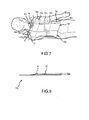
- Fig. 8 shows an exemplary dimple matrix within a portion of the side flap segment 16b of pad 10.
- the first layers 26, 126 of the back pad 10, 100 may comprise a molded foam material that integrally defines the noted dimple matrices as well as the rib members which define the various fluid channels comprising the fluid containing layers 20, 120. Additionally, the molded foam material may define the noted dimple matrices.
- the second layers 28, 128 of the fluid containing layers 20, 120 may comprise a flexible membrane (e.g. polyolefin, polyurethane, flexible polyvinylchloride) that is sealed around the periphery and across interfacing top end portions of the various ribs and dimples comprising the fluid containing layers 20, 120.
- the conformable layer 60, 160 may comprise a first material suspended in a matrix defined by a second material.
- the first material may comprise a liquid and the second material may comprise a polymer.
- conformable layer 60, 160 may comprise a hydrogel that yields an adhesive surface 62, 162 that provides a desirable adhesive and conformable interface with the skin of a patient.
- the utilization of such hydrogel material also facilitates thermal exchange between the fluid containing layer 20, 120 of back pad 10, 100 and a patient.
- first layers 26, 126, second layers 28, 128, conformable layers 60, 160 and dimple matrices may be provided utilizing the teachings of U.S. Patent No. 6,197,045 entitled “COOLING/HEATING PAD AND SYSTEM”, and U.S. Patent Application Serial No. 09/476,850 entitled “COOLING/HEATING PAD AND SYSTEM”, filed January 3, 2000, each hereby incorporated by reference in its entirety.
- back pad 10 may comprise a number of peripheral adhesive strips 80 each having a selectively removable release liner exposed thereupon.
- strips 80 may comprise a polyolefin or polyurethane film with hypoallergenic pressure sensitive acrylate adhesive anchored to the pad 10, 100 with a rubber based pressure sensitive adhesive.
- adhesive strips 80a, 80b, 80c are located on the side segments 16a, 16b, 16c, respectively, for selective removal upon positioning the back pad 10 on a patient. That is, such adhesive strips 80a, 80b, 80c may be utilized to facilitate the securement of the edges of side flap segment 16a, 16b, 16c to a patient. Similarly, an adhesive strip 80d may be provided along the end flap segment 14 for selective use in securing the end flap segment 14 to a patient.
- ports 22, 122 and 24, 124 may be selectively established to provide various advantages.
- ports 22, 122 and 24, 124 may be provided to avoid patient weight from creating localized high pressure areas on the skin by pressing the port or attached tubing against the skin of a patient. Reducing such high pressure areas reduces any risk of pressure ulcers.
- the tubing can exit off an operating table without multiple turns, thereby reducing any risk of interconnected tubing buckling/kinking which limits fluid flow.
- ports 22 and 24 are both provided in the end flap segment 14. Further, it can be seen that ports 22 and 24 each include an elongated opening through the first layer 26 into the fluid containing layer 20. Correspondingly, elongated port members 92, 94 are interconnected to the outside, exposed surface of the first layer 26, wherein the elongated openings of ports 22, 24 are in aligned relation with the elongated port members 92, 94.
- the center axes for ports 22, 24 and the corresponding port members 92, 94 extend laterally away from the peripheral edge 11 and central segment 12 of the back pad 10 in parallel co-relation.
- the port members 92, 94 are also tapered as they extend laterally outward to accommodate patient comfort considerations and provide a smooth fluid flow transition.
- back pads 10a, 10b may be provided in a plurality of different sized sets. As such, use of back pad 10a, 10b may first entail the selection of the best fit set, e.g. based on patient height.
- Figs. 6A, 6B, 6C illustrate initial positioning of pad 10b.
- the release liner 70 may be removed from pad 10b and the middle flap segment 16b may be positioned along the mid-axilla of a patient.
- the bony prominence at the top of the spine of the patient i.e. protruding just below the neck region
- the top edge of the end flap segment 14 of the back pad 10b may be located along a lateral line that extends cross-wise a few inches below the noted bony prominence.
- the patient is lying down, such top edge may be placed closer to the lateral line.
- the patient may be rolled onto his/her right shoulder during placement of pad 10b.
- the upper side flap segment 16a may be lightly positioned on the triceps area of a patient. Further, the pad 10b may be lightly pressed across its lateral extent. At this point, the liners may be removed from the adhesive strips 80b, 80c, 80d, whereupon the adhesive strips are secured to the interfacing skin regions of a patient. Thereafter, the arms of a patient can be tucked to the patient's side and the top side flap segment 16a repositioned thereupon. To maintain such position of segment 16a, the liner may be removed from the adhesive strip 80a and such strip 80a may be secured to the patient's skin.
- back pad 10a may be positioned utilizing a similar procedure. If the patient is lying down, the patient may be rolled onto his/her left shoulder before placement of pad 10a. As may be appreciated, back pad 10a may be conveniently overlapped on back pad 10b as necessary along the spinal interface region. Such overlap may be advantageously maintained due to the adhesive surface 62 presented by the conformable layer 60. Such overlap capability facilitates utilization of pads 10a, 10b on a variety of patient sizes.
- pivot axes are provided in relation to the side flaps segments 16a, 16b, 16c and end flap segment 18.
- the pivot axis for end flap segment 18 preferably forms an angle of between about 70° and 110° relative to the pivot axes of side flap segments 16a, 16b, 16c.
- Such relative orientation of the axes accommodates conformable positioning of the pads 10a, 10b across the various corresponding body regions (e.g. shoulders, rib cage, lower back-to-hip/buttocks regions) which have differing, complex configurations.
- ports 22, 24 in end flap segment 14 allows for ready access thereto and avoids patient discomfort that could result from "sandwiching" of such ports between a patient and a support surface. Further, such positioning directs fluid tubing that is interconnected to ports 22, 24 laterally away from the patient, thereby reducing kinking considerations and otherwise reducing potential obstructions for patient care by medical personnel.
Landscapes
- Health & Medical Sciences (AREA)
- Vascular Medicine (AREA)
- Thermal Sciences (AREA)
- Engineering & Computer Science (AREA)
- Biomedical Technology (AREA)
- Heart & Thoracic Surgery (AREA)
- Physics & Mathematics (AREA)
- Life Sciences & Earth Sciences (AREA)
- Animal Behavior & Ethology (AREA)
- General Health & Medical Sciences (AREA)
- Public Health (AREA)
- Veterinary Medicine (AREA)
- Thermotherapy And Cooling Therapy Devices (AREA)
Applications Claiming Priority (4)
| Application Number | Priority Date | Filing Date | Title |
|---|---|---|---|
| US10/087,534 US6648905B2 (en) | 2002-02-27 | 2002-02-27 | Enhanced medical thermal energy exchange pad |
| US10/087,533 US6669715B2 (en) | 2002-02-27 | 2002-02-27 | Medical thermal energy exchange pad |
| EP02806905.2A EP1487386B1 (fr) | 2002-02-27 | 2002-11-20 | Modèle amelioré de compresse medicale d'échange d'énergie thermique |
| PCT/US2002/037075 WO2003071998A1 (fr) | 2002-02-27 | 2002-11-20 | Modele ameliore de compresse medicale d'echange d'energie thermique |
Related Parent Applications (3)
| Application Number | Title | Priority Date | Filing Date |
|---|---|---|---|
| EP02806905.2 Division | 2002-11-20 | ||
| EP02806905.2A Division-Into EP1487386B1 (fr) | 2002-02-27 | 2002-11-20 | Modèle amelioré de compresse medicale d'échange d'énergie thermique |
| EP02806905.2A Division EP1487386B1 (fr) | 2002-02-27 | 2002-11-20 | Modèle amelioré de compresse medicale d'échange d'énergie thermique |
Publications (2)
| Publication Number | Publication Date |
|---|---|
| EP2543348A1 true EP2543348A1 (fr) | 2013-01-09 |
| EP2543348B1 EP2543348B1 (fr) | 2020-03-18 |
Family
ID=27767348
Family Applications (2)
| Application Number | Title | Priority Date | Filing Date |
|---|---|---|---|
| EP12187487.9A Expired - Lifetime EP2543348B1 (fr) | 2002-02-27 | 2002-11-20 | Compresse médicale d'échange thermique améliorée |
| EP02806905.2A Expired - Lifetime EP1487386B1 (fr) | 2002-02-27 | 2002-11-20 | Modèle amelioré de compresse medicale d'échange d'énergie thermique |
Family Applications After (1)
| Application Number | Title | Priority Date | Filing Date |
|---|---|---|---|
| EP02806905.2A Expired - Lifetime EP1487386B1 (fr) | 2002-02-27 | 2002-11-20 | Modèle amelioré de compresse medicale d'échange d'énergie thermique |
Country Status (5)
| Country | Link |
|---|---|
| EP (2) | EP2543348B1 (fr) |
| JP (1) | JP4455060B2 (fr) |
| AU (1) | AU2002356976A1 (fr) |
| CA (1) | CA2477113C (fr) |
| WO (1) | WO2003071998A1 (fr) |
Families Citing this family (3)
| Publication number | Priority date | Publication date | Assignee | Title |
|---|---|---|---|---|
| US7181927B2 (en) * | 2005-07-01 | 2007-02-27 | Alsius Corporation | Primary heat exchanger for patient temperature control |
| CN105007866B (zh) * | 2013-01-29 | 2017-08-08 | 梅迪万斯股份有限公司 | 具有增加的水流通面积的混合医疗冷却垫 |
| JP6366982B2 (ja) * | 2014-04-02 | 2018-08-01 | アトムメディカル株式会社 | 低温療法用パッド |
Citations (7)
| Publication number | Priority date | Publication date | Assignee | Title |
|---|---|---|---|---|
| US3830676A (en) * | 1973-02-28 | 1974-08-20 | Acurex Corp | Process of making a contoured thermal device |
| GB1462033A (en) * | 1973-01-19 | 1977-01-19 | Secr Defence | Apparatus for 0ntrolling the temperature of the human body |
| US4114620A (en) * | 1977-03-02 | 1978-09-19 | Moore-Perk Corporation | Patient treatment pad for hot or cold use |
| US4149541A (en) * | 1977-10-06 | 1979-04-17 | Moore-Perk Corporation | Fluid circulating pad |
| US5989285A (en) * | 1996-08-15 | 1999-11-23 | Thermotek, Inc. | Temperature controlled blankets and bedding assemblies |
| US6113626A (en) * | 1998-04-23 | 2000-09-05 | The Board Of Regents Of The University Of Texas System | Heat transfer blanket for controlling a patient's temperature |
| US6197045B1 (en) | 1999-01-04 | 2001-03-06 | Medivance Incorporated | Cooling/heating pad and system |
Family Cites Families (12)
| Publication number | Priority date | Publication date | Assignee | Title |
|---|---|---|---|---|
| US3674019A (en) * | 1970-10-23 | 1972-07-04 | Grant Airmass Corp | Dual layer cellular inflatable pad |
| EP0168483A4 (fr) * | 1984-01-18 | 1987-01-20 | Bailey David F | Couverture thermique medicale jetable a couches multiples. |
| US5662695A (en) * | 1990-09-05 | 1997-09-02 | Breg, Inc. | Occlusion-resistant fluid pad conformable to a body for therapeutic treatment thereof |
| US5449379A (en) * | 1993-07-21 | 1995-09-12 | Alternative Compression Technologies, Inc. | Apparatus for applying a desired temperature and pressure to an injured area |
| US5411542A (en) * | 1993-10-20 | 1995-05-02 | Hollister Incorporated | Post-operative thermal blanket for ankle and foot |
| US6230501B1 (en) * | 1994-04-14 | 2001-05-15 | Promxd Technology, Inc. | Ergonomic systems and methods providing intelligent adaptive surfaces and temperature control |
| US5800480A (en) * | 1996-08-30 | 1998-09-01 | Augustine Medical, Inc. | Support apparatus with a plurality of thermal zones providing localized cooling |
| US5806335A (en) * | 1997-02-13 | 1998-09-15 | Pabban Development Inc | Cold therapy device |
| US6109338A (en) * | 1997-05-01 | 2000-08-29 | Oceaneering International, Inc. | Article comprising a garment or other textile structure for use in controlling body temperature |
| US6117164A (en) * | 1997-06-06 | 2000-09-12 | Dj Orthopedics, Llc | Flexible multijoint therapeutic pads |
| US5967225A (en) * | 1998-01-16 | 1999-10-19 | Jenkins; Donny Ray | Body heating/cooling apparatus |
| US6238427B1 (en) * | 1999-03-30 | 2001-05-29 | John G. Matta | Therapeutic heat transfer pads |
-
2002
- 2002-11-20 WO PCT/US2002/037075 patent/WO2003071998A1/fr active Application Filing
- 2002-11-20 EP EP12187487.9A patent/EP2543348B1/fr not_active Expired - Lifetime
- 2002-11-20 AU AU2002356976A patent/AU2002356976A1/en not_active Abandoned
- 2002-11-20 JP JP2003570746A patent/JP4455060B2/ja not_active Expired - Lifetime
- 2002-11-20 CA CA002477113A patent/CA2477113C/fr not_active Expired - Lifetime
- 2002-11-20 EP EP02806905.2A patent/EP1487386B1/fr not_active Expired - Lifetime
Patent Citations (7)
| Publication number | Priority date | Publication date | Assignee | Title |
|---|---|---|---|---|
| GB1462033A (en) * | 1973-01-19 | 1977-01-19 | Secr Defence | Apparatus for 0ntrolling the temperature of the human body |
| US3830676A (en) * | 1973-02-28 | 1974-08-20 | Acurex Corp | Process of making a contoured thermal device |
| US4114620A (en) * | 1977-03-02 | 1978-09-19 | Moore-Perk Corporation | Patient treatment pad for hot or cold use |
| US4149541A (en) * | 1977-10-06 | 1979-04-17 | Moore-Perk Corporation | Fluid circulating pad |
| US5989285A (en) * | 1996-08-15 | 1999-11-23 | Thermotek, Inc. | Temperature controlled blankets and bedding assemblies |
| US6113626A (en) * | 1998-04-23 | 2000-09-05 | The Board Of Regents Of The University Of Texas System | Heat transfer blanket for controlling a patient's temperature |
| US6197045B1 (en) | 1999-01-04 | 2001-03-06 | Medivance Incorporated | Cooling/heating pad and system |
Also Published As
| Publication number | Publication date |
|---|---|
| EP1487386B1 (fr) | 2015-09-23 |
| JP2005518836A (ja) | 2005-06-30 |
| CA2477113A1 (fr) | 2003-09-04 |
| EP2543348B1 (fr) | 2020-03-18 |
| WO2003071998A1 (fr) | 2003-09-04 |
| AU2002356976A1 (en) | 2003-09-09 |
| EP1487386A1 (fr) | 2004-12-22 |
| JP4455060B2 (ja) | 2010-04-21 |
| CA2477113C (fr) | 2009-02-03 |
| EP1487386A4 (fr) | 2010-04-07 |
Similar Documents
| Publication | Publication Date | Title |
|---|---|---|
| US6669715B2 (en) | Medical thermal energy exchange pad | |
| US6648905B2 (en) | Enhanced medical thermal energy exchange pad | |
| JP6644747B2 (ja) | 拡大した流水面積を有するハイブリッド医療用冷却パッド | |
| EP1616543B1 (fr) | Coussin de refroidissement et de chauffage perfectionné et système | |
| CA2445526C (fr) | Appareil et procede pour chauffer et refroidir une region localisee du corps | |
| US9687386B2 (en) | Cooling medical pad | |
| US20030069621A1 (en) | Heat exchanger garment | |
| US20030229385A1 (en) | Cooling/heating system | |
| EP3177242A1 (fr) | Échangeur de chaleur à sections multiples intégré | |
| EP1487386B1 (fr) | Modèle amelioré de compresse medicale d'échange d'énergie thermique | |
| US20240108497A1 (en) | Soft Border for Targeted Temperature Management | |
| US20220304847A1 (en) | Reconfiguration Compatible Thermal Pad | |
| EP4281023A1 (fr) | Tampon médical de refroidissement/chauffage à bords ramollis | |
| WO2023140836A1 (fr) | Compresse à contact thermique hautement confortable |
Legal Events
| Date | Code | Title | Description |
|---|---|---|---|
| PUAI | Public reference made under article 153(3) epc to a published international application that has entered the european phase |
Free format text: ORIGINAL CODE: 0009012 |
|
| AC | Divisional application: reference to earlier application |
Ref document number: 1487386 Country of ref document: EP Kind code of ref document: P |
|
| AK | Designated contracting states |
Kind code of ref document: A1 Designated state(s): DE FR GB |
|
| 17P | Request for examination filed |
Effective date: 20130701 |
|
| RBV | Designated contracting states (corrected) |
Designated state(s): DE FR GB |
|
| 17Q | First examination report despatched |
Effective date: 20130930 |
|
| REG | Reference to a national code |
Ref country code: DE Ref legal event code: R079 Ref document number: 60250108 Country of ref document: DE Free format text: PREVIOUS MAIN CLASS: A61F0007000000 Ipc: A61F0007020000 |
|
| GRAP | Despatch of communication of intention to grant a patent |
Free format text: ORIGINAL CODE: EPIDOSNIGR1 |
|
| STAA | Information on the status of an ep patent application or granted ep patent |
Free format text: STATUS: GRANT OF PATENT IS INTENDED |
|
| RIC1 | Information provided on ipc code assigned before grant |
Ipc: A61F 7/02 20060101AFI20190826BHEP Ipc: A61F 7/00 20060101ALI20190826BHEP |
|
| INTG | Intention to grant announced |
Effective date: 20191001 |
|
| GRAS | Grant fee paid |
Free format text: ORIGINAL CODE: EPIDOSNIGR3 |
|
| GRAA | (expected) grant |
Free format text: ORIGINAL CODE: 0009210 |
|
| STAA | Information on the status of an ep patent application or granted ep patent |
Free format text: STATUS: THE PATENT HAS BEEN GRANTED |
|
| AC | Divisional application: reference to earlier application |
Ref document number: 1487386 Country of ref document: EP Kind code of ref document: P |
|
| AK | Designated contracting states |
Kind code of ref document: B1 Designated state(s): DE FR GB |
|
| REG | Reference to a national code |
Ref country code: GB Ref legal event code: FG4D |
|
| REG | Reference to a national code |
Ref country code: DE Ref legal event code: R096 Ref document number: 60250108 Country of ref document: DE |
|
| REG | Reference to a national code |
Ref country code: DE Ref legal event code: R097 Ref document number: 60250108 Country of ref document: DE |
|
| PLBE | No opposition filed within time limit |
Free format text: ORIGINAL CODE: 0009261 |
|
| STAA | Information on the status of an ep patent application or granted ep patent |
Free format text: STATUS: NO OPPOSITION FILED WITHIN TIME LIMIT |
|
| 26N | No opposition filed |
Effective date: 20201221 |
|
| PGFP | Annual fee paid to national office [announced via postgrant information from national office to epo] |
Ref country code: GB Payment date: 20211020 Year of fee payment: 20 Ref country code: DE Payment date: 20211020 Year of fee payment: 20 |
|
| PGFP | Annual fee paid to national office [announced via postgrant information from national office to epo] |
Ref country code: FR Payment date: 20211020 Year of fee payment: 20 |
|
| REG | Reference to a national code |
Ref country code: DE Ref legal event code: R071 Ref document number: 60250108 Country of ref document: DE |
|
| REG | Reference to a national code |
Ref country code: GB Ref legal event code: PE20 Expiry date: 20221119 |
|
| PG25 | Lapsed in a contracting state [announced via postgrant information from national office to epo] |
Ref country code: GB Free format text: LAPSE BECAUSE OF EXPIRATION OF PROTECTION Effective date: 20221119 |