EP2542923B1 - Underwater sensor apparatus - Google Patents
Underwater sensor apparatus Download PDFInfo
- Publication number
- EP2542923B1 EP2542923B1 EP11751444.8A EP11751444A EP2542923B1 EP 2542923 B1 EP2542923 B1 EP 2542923B1 EP 11751444 A EP11751444 A EP 11751444A EP 2542923 B1 EP2542923 B1 EP 2542923B1
- Authority
- EP
- European Patent Office
- Prior art keywords
- housing
- sensors
- sensor apparatus
- data
- underwater sensor
- Prior art date
- Legal status (The legal status is an assumption and is not a legal conclusion. Google has not performed a legal analysis and makes no representation as to the accuracy of the status listed.)
- Active
Links
Images








Classifications
-
- G—PHYSICS
- G01—MEASURING; TESTING
- G01C—MEASURING DISTANCES, LEVELS OR BEARINGS; SURVEYING; NAVIGATION; GYROSCOPIC INSTRUMENTS; PHOTOGRAMMETRY OR VIDEOGRAMMETRY
- G01C13/00—Surveying specially adapted to open water, e.g. sea, lake, river or canal
-
- G—PHYSICS
- G01—MEASURING; TESTING
- G01N—INVESTIGATING OR ANALYSING MATERIALS BY DETERMINING THEIR CHEMICAL OR PHYSICAL PROPERTIES
- G01N33/00—Investigating or analysing materials by specific methods not covered by groups G01N1/00 - G01N31/00
- G01N33/18—Water
- G01N33/1886—Water using probes, e.g. submersible probes, buoys
-
- G—PHYSICS
- G01—MEASURING; TESTING
- G01D—MEASURING NOT SPECIALLY ADAPTED FOR A SPECIFIC VARIABLE; ARRANGEMENTS FOR MEASURING TWO OR MORE VARIABLES NOT COVERED IN A SINGLE OTHER SUBCLASS; TARIFF METERING APPARATUS; MEASURING OR TESTING NOT OTHERWISE PROVIDED FOR
- G01D11/00—Component parts of measuring arrangements not specially adapted for a specific variable
- G01D11/24—Housings ; Casings for instruments
- G01D11/245—Housings for sensors
-
- G—PHYSICS
- G01—MEASURING; TESTING
- G01N—INVESTIGATING OR ANALYSING MATERIALS BY DETERMINING THEIR CHEMICAL OR PHYSICAL PROPERTIES
- G01N1/00—Sampling; Preparing specimens for investigation
- G01N1/02—Devices for withdrawing samples
- G01N2001/021—Correlating sampling sites with geographical information, e.g. GPS
Definitions
- water temperature, depth, conductivity, salinity, sound speed, optical properties, nutrient availability, etc. may provide valuable information for a number of divergent uses. This information may be used to expand the knowledge base of ocean parameters in general, or may be useful in navigation, sonar communication and the like.
- WO 00/39533 A1 describes a cover or a lid, preferably a battery cover, that is positioned in the housing of a water-tight measurement device.
- a water-tight pressure-equalization membrane is arranged in said cover.
- WO 93/17334 A1 discloses a portable free drifting oceanographic instrument package for cyclically collecting oceanic and/or fresh water environmental data over a range of depths.
- EP 1 962 089 A1 discloses an expendable launchable probe for temperature and fluorescence measurements of the undersea environment.
- the probe comprises a central body made of anticorodal aluminium tube where water flows inside.
- a measurement cell In the internal part of the tube a measurement cell is fixed, where sensors are placed in direct touch with water and, on external part of the tube, batteries and electronics are placed.
- US 6,456,197 B1 describes a self-righting buoy having an oil/water sensor for the detection of floating oil on the sea surface.
- Underwater sensor apparatus 10 comprises two housing components 12a, 12b and jacket 14.
- a first housing component 12a houses the display 16 and includes window 22 to allow visual access to the display or graphical user interface 16 by the user of the apparatus.
- display 16 may be a liquid crystal display (LCD) or may use other suitable display technologies.
- a stylus 50 may be provided for user to interact with the display 16 through the use of magnetic switches 52a, 52b, 52c included inside the housing.
- the housing further includes a recess for each switch to minimize the chance of an unintended activation of a switch. This is accomplished by mounting the magnetic switch adjacent to the bottom of a recess.
- the magnetic stylus is inserted into the recess. These switches or buttons may be waterproof so they are protected from water damage. As described in more detail herein, stylus 50 is used to activate magnetic switches 52 to input data, activate a system activity, activate a screen or otherwise navigate the display 16. LED 54 emits light to signal, e.g., that the apparatus's power is on.
- a second housing component 12b is configured to house one or more sensors and/or probes used to collect and measure various underwater parameters, which will be described in more detail herein.
- an interface module 20 stands between display 16 and sensor board 24 and provides both a structural and electrical interconnection between the sensors and/or probes located within housing component 12b and the display located within housing component 12a. More particularly, graphical user interface or display 16 is fastened to interface module 20 using screws 19a-19c threaded through standoffs 21a-21c. Interface module 20 is, in turn, fastened to sensor board 24 via screws 15a, 15b threaded through standoffs 23a, 23b. First housing component 12a and second housing component 12b are attached by fastener assemblies including screws and O-rings 17, 18 with the display 16, interface module 20 and various sensors and/or probes securely held and sealed within the housing components 12a, 12b.
- Endcap component 26 is a substantially hollow rounded end piece that connects to both housing components 12a, 12b by a screw and socket mechanism 28. Endcap component 26 also serves as an enclosure for battery 30 and contains battery contact 32.
- the underwater sensor apparatus 10 is powered by two double AA batteries, which can be loaded and replaced without the use of tools. Endcap component 26 may be weighted to provide directional stability and control, making the underwater sensor apparatus 10 easier and faster to deploy. Weighting may be accomplished by adding weight to the endcap end of the unit such that the device descends endcap end first. The batteries located in the endcap component 26 can provide such weighting.
- the second housing component 12b defines a channel 36 that extends substantially vertically through the back of the component. Each end of the channel may have a funnel-shaped portion 37.
- Channel 36 contains the access points 68for at least some of the apparatus's sensors and probes so that these components are protected from damage.
- Channel 36 has a self-flushing design that acts as a natural pump to provide the advantage of facilitating water flow on the apparatus' sensors and probes for improved data collection.
- the weight distribution of housing components 12a, 12b ensures that the underwater sensor apparatus 10 falls vertically when being submerged and maintains a vertical orientation when being pulled up out of the water. In this manner, as the device moves through the water, the amount of water flowing through the channel is increased for both data collection passes and for flushing purposes.
- the apparatus moves either up or down through the water, the water is constantly pushed through channel 36.
- new water is constantly replacing water at the level of each sensor so the sensors get data readings at every water level.
- This ensures accurate data readings, particularly for the temperature sensor 70, which needs a constant rate of water flow to measure temperature accurately.
- the vertical orientation allows the user to measure the rate of fall by monitoring changes in pressure.
- the user can use flow measurements to correct problems relating to water flow rate that may occur with the temperature sensor 70.
- Jacket 14 may have any formation suitable to provide adequate protection for the housing 12 and the components therein, and an exemplary configuration will now be described.
- Jacket 14 comprises top and bottom attachment portions 38a, 38b, and each attachment portion defines an aperture 40 suitable for threading and securing attachment mechanisms such as chain links or cable.
- the front section of jacket 14 includes a rounded top shell portion 42, a rounded bottom shell portion 44 and middle cross portion 46 to provide extra protection and support.
- Top shell portion 42 covers the top front of housing component 12a
- bottom shell portion 44 covers the bottom front of housing component 12b.
- jacket 14 Between top shell portion 42 and middle cross portion 46, jacket 14 defines a first cutout 48 sized and shaped to allow the user easy access to magnetic switches 52a, 52b and viewing of display 16.
- Jacket 14 defines a second cutout 56 between middle cross portion 46 and bottom shell portion 44.
- the back of jacket 14 defines a top and bottom cutout 60a, 60b sized to expose the top and bottom openings of channel 36.
- Center portion 62 of the back of the jacket 14 defines a series of alternating lateral strips 64 and cutouts 66. This arrangement of strips 64 and cutouts 66 provides additional stability and support for housing component 12b.
- the sensor apparatus 10 comprises temperature sensor 70, which is disposed in housing component 12b and extends into channel 36 through an access point 68 so that it can measure the temperature of the water when submerged.
- Temperature sensor 70 may be of any suitable type, e.g., a thermistor, which is one of the most accurate types of temperature sensors.
- a thermistor is an element composed of a material that exhibits a large change in resistance proportional to a small change in temperature. Thermistors usually have negative temperature coefficients, which means the resistance of the thermistor decreases as the temperature increases.
- housing component 12b Also disposed within housing component 12b are conductivity electrodes 74 and pressure sensor 20.
- conductivity electrodes are made of titanium to provide more robust conductivity, but they may be made of any suitable conductive material.
- Pressure cal module 72 is a circuit board that facilitates operative connection of sensors to the underwater sensor apparatus 10 without the need for additional wires.
- the pressure cal module 72 may be mounted flush to the housing, and wires from the sensors may soldered to the pressure cal module.
- the pressure cal module may contain pads to support some calibration resistors that are specific to the installed pressure sensor, and then passes the conditioned signals on to the main circuit board via a connector (not shown).
- housing components 12a, 12 can be manufactured separately and more cheaply because pressure cal module 72 facilitates their operational interconnection.
- conductivity electrodes 74 are located below the temperature sensor 70.
- the conductivity electrodes 74 extend out of housing component 12b into channel 36 through access points 68 so that they can measure the conductivity when submerged.
- Pressure sensor 76 is disposed within the bottom of housing component 12b and plugs hole 78. Wires 77 extend through the hole 78 into housing component 12b and are connected to pressure cal module 72.
- the pressure sensor 76 is exposed to water via a hole (not shown) in the right inner side of channel 36, so that pressure sensor 76 can make pressure readings.
- the underwater sensor apparatus also contains a central processing unit (CPU) 80, or controller, on which software is run to process the collected data.
- the CPU may be any form of controller or microprocessor.
- the user prepares the underwater sensor apparatus 10 for a cast by using the stylus 50, which may be a magnetic stylus having a magnetic tip, to program the apparatus to collect the desired water characteristics. These characteristics could include temperature, pressure, conductivity and depth, among others.
- the user first turns the underwater sensor apparatus 10 on by activating one of the magnetic switches 52a, 52b, 52c with the stylus 50. LED 54 will emit light to indicate that the apparatus is on.
- the user again activates one of the magnetic switches 52a, 52b with the stylus 50 to select the "Cast" icon on the display 16, which may be waterproof.
- the magnetic stylus 50 and magnetic switches 52 may be used for any kind of data input and for navigating various screens on the display 16. Magnetic switches are advantageous because they have no moving parts, can be used both in and out of the water and rarely fail in the field.
- the GPS 110 automatically provides the user with geographic data, including the exact position, date and time of the cast via the display 16. Finally, the user selects the icon for starting data collection and lowers the underwater sensor apparatus 10 into the water. This may be done by securing attachment mechanisms such as chain links or cable to aperture 40 of top attachment portion 38a of the apparatus jacket 14. After attaching the cable or line, the device is lowered into the water. Typically the device is allowed to free-fall, although it is possible to control the descent speed by controlling the deployment of the line or cable. The device is allowed to descend to a predetermined depth or to the bottom depending on the test parameters. Once the bottom or desired depth is reached the device is retrieved by reeling in the line or cable. Once the underwater sensor apparatus 10 is out of the water the user can view the data on the display 16, as best seen in FIGS. 12 and 13 , or wirelessly download the data to a computer.
- securing attachment mechanisms such as chain links or cable to aperture 40 of top attachment portion 38a of the apparatus jacket 14.
- pressure sensor 20 and temperature sensor or thermistor probe 70 are operatively connected to pressure cal module 72, which, in turn, is operatively connected to sensor board 82.
- the sensor board 82 is operatively connected to interface board 84, which, in turn, is operatively connected to display 16.
- Battery 30 is connected to interface board 84 via battery contact 32.
- Interface board comprises GPS capability 110 and transceiver 112 to provide bluetooth capability. The bluetooth capability eliminates the need for various connectors and cables to start, program, review or download data.
- LED 54 is also located on interface board 84.
- Sensor board 82 comprises power supply 86, which provides power to CPU 80, recorder 88 and PI filter 92 to prevent supply noise from affecting the system.
- CPU 80 comprises analog-to-digital converter (ADC) 94 and digital-to-analog converter (DAC) 96.
- the CPU 80 controls de-bug port 90 and receives data from pressure circuit 98 and temperature circuit 100 upon those components receiving pressure and temperature data from pressure sensor 20 and temperature probe 70, respectively.
- DAC 96 conducts waveform conditioning 102 and conductivity drive and scale selection 104.
- Conductivity electrodes 74 feed data into sensor board 82, which conducts signal selection 106 and signal amplification and conditioning 108 before feeding the conductivity data to ADC 94 in CPU 80.
- Voltage references 114 are provided to the temperature circuit 100 and the pressure circuit 98 and are used to conduct signal amplification and conditioning 108.
- Waveform conditioning 102, conductivity drive and scale selection 104, signal selection 106 and signal amplification and conditioning 108 are performed by conductivity block or circuit 116.
- the waveform or frequency output may be arbitrary and could comprise sine waves. Several frequency simulations could be used and could be modulated to reduce capacitance.
- the conductivity block also measures current and phase information.
- One possible configuration of conductivity block is the six circuit design, as best seen in FIG. 14 .
- the underwater sensor apparatus 10 After the underwater sensor apparatus 10 boots up 2000, it reads the configuration parameters 2002 that are entered in by the user and computes DAC output waveforms 2004. The underwater sensor apparatus 10 then waits for the user to indicate the start of data acquisition mode 2006. Upon receiving the instruction to start data acquisition, the underwater sensor apparatus 10 effects several steps to prepare for data acquisition. These steps 2008 include calibrating analog-to-digital (ADC) converters, setting up and running data acquisition timers, setting initial resistor range and starting DAC waveform output. The sample accumulators may be reset 2010, and the underwater sensor apparatus 10 will check the acquired data readings to determine if they correlate to the user requested readings in an average interval 2012. If the average interval is complete, the underwater sensor apparatus 10 will check if there are any accumulated readings 2026.
- ADC analog-to-digital
- the sample mean temperature, pressure, conductivity A and conductivity B will be calculated.
- the underwater sensor apparatus 10 will also compute the mean for all other requested parameters for diagnostic purposes and may collect sample statistics as well. If there are no accumulated readings, a bad sample will be generated 2028.
- the next steps 2032 may include recording either the accumulated reading or the bad sample to an internal recorder, outputting the sample on the display 16 and/or transmitting the sample via the underwater sensor apparatus's bluetooth capability.
- the underwater sensor apparatus 10 will then determine if the user requested to end sampling 2034 and, if so, will complete data acquisition. If the user has not requested to end sampling, the underwater sensor apparatus 10 will continue data acquisition by reverting to step 2010 and reset sample accumulators.
- the underwater sensor apparatus 10 will read more samples from temperature sensor 70, conductivity electrode 74, pressure sensors 20, 76 and a range resistor and store the sampled values in ADC counts 2014. One or more of the parameters temperature, pressure, phaseA, resistanceA, conductivityA, phaseB, resistanceB and conductivityB may be computed 2016. The underwater sensor apparatus 10 will then check the readings to determine if the measurements were done in the requested range 2018. If they were done correctly, the last reading will be accumulated 2020. If they were done in the wrong range, a new range will be selected, the DAC waveform will be re-programmed and the range resistors may be switched. Then the underwater sensor apparatus 10 will revert to step 2012 and again determine whether the acquired readings correspond to the requested readings.
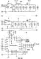
- FIGS. 14A-B and 16A-18C are system block and circuit diagrams that show the electrical connections of various sections of the underwater sensor apparatus. More particularly, FIGS. 14A-B is a system block diagram showing an overview of the electrical connections of an embodiment of an underwater sensor apparatus.
- FIGS. 16A-C is a schematic circuit diagram showing a portion of sensor board 82.
- FIGS. 17A-C is a schematic circuit diagram showing interface board 84.
- FIGS. 18A-C is a schematic circuit diagram showing another portion of sensor board 82 including main power supply 86, auxiliary power supply 87 and CPU 80.
- FIG. 9 is a flow chart showing some of the different paths the user can take to view different screens on the display. Each screen is designed for a specific system function.
- a start screen / logo screen 210 is displayed.
- Start screen 210 may display brand information such as words or designs showing the name of the manufacturer of the underwater sensor apparatus or a trademark associated with the product.
- the first screen with operational information on display 16 is home screen 220, which displays a menu of icons offering different functions.
- the menu of home screen 220 includes three branches and each branch is represented by an icon on the display screen.
- the first branch is a data collection branch that activates the GPS and starts data collection.
- the icon representing the data collection branch may be referred to as the "Cast" icon 222.
- the second branch represented by the "Review” icon 224, provides a pathway to review collected data and displays the data in both text and graph form.
- the third branch is a system information branch having a system icon 226, which may be represented by a letter "i" and displays information about the underwater sensor apparatus.
- Home screen 220 may also include various other icons to indicate parameters such as a recorder status indicator 221 showing how full the recorder is with data, a battery life indicator 223, a Bluetooth indicator 225 showing whether Bluetooth is on or off, and the system serial number 227 and to provide the ability to move to other screens.
- a "House" icon indicates that the user is on the home screen 220.
- Typical use would include first activating the GPS and data collection using the Cast icon 222 and then viewing the collected data using the Review icon 224.
- pressing the "execute” button 52b will activate the command associated with the selected icon.
- Pushing the "execute” button 52b with the cast icon 222 selected will activate a "Wait for GPS Before Cast” screen 230.
- Pushing the "execute” button 52b with the review icon 224 selected will activate a Data File review screen 240, and pushing the "execute” button 52b with the system icon 226 selected will activate a System Status screen 250.
- the "Wait for GPS Before Cast” screen 230 allows the user to prepare the system for cast or deployment by displaying real-time data from the GPS for determining the accuracy of the displayed location.
- the Wait for GPS Before Cast screen 230 may show the date and time and GPS position information in the form of latitude and longitude numbers.
- a circle icon (not shown) may change color with different colors indicating the quality of the location or GPS position. For example, a green light may indicate a good GPS position, a red light may indicate no GPS position, and a yellow light may indicate a satisfactory GPS position.
- a GPS quality indicator may also include varying numbers of bars of varying lengths. The user pushes button 52b to record the GPS location before casting the underwater sensor apparatus 10, and the button 52b is pressed again to start collecting data such as conductivity, temperature and pressure.
- the underwater sensor apparatus 10 is then ready for deployment and a Data Acquisition screen 260 is displayed.
- This screen indicates that data is being recorded onboard the underwater sensor apparatus 10.
- the Data Acquisition screen 260 shows temperature, conductivity and pressure readings beneath large letters indicating that the device is recording data.
- the underwater sensor apparatus 10 may be secured with a line and tossed into the water.
- the screen is dimmable and may dim after deployment to conserve power.
- the underwater sensor apparatus 10 will measure and record data as it descends through the water, including, for example temperature data 262, conductivity data 264, sound speed data, salinity data, and pressure data 266.
- the device Once the device has reached the bottom of the body of water, it can be pulled back up using the attached line, and it will continue measuring and recording data as it ascends back up to the surface of the water.
- the user Upon retrieval of the underwater sensor apparatus 10, the user may push any button to activate the display and then push any button a second time to end the cast, close the data file, and start the GPS.
- a second GPS location is then recorded at the end of the cast. This is particularly advantageous where the underwater sensor apparatus 10 has been cast from a moving boat.
- a "Wait for GPS after Cast" screen 270 appears next. This screen is similar to the Wait for GPS Before Cast screen 230 described above in that it displays location information such as latitude and longitude numbers, and indicates GPS signal quality by, e.g., a varying number and length of signal strength bars.
- the user pushes button 52b after the cast to record the location and can decide whether or not to wait for a good GPS position. As discussed above, a color-coded indicator uses green, yellow and red to indicate the quality of the GPS position. Pushing button 52a from this screen will return the user to Home Screen 220.
- Data File review screen 240 appears when the user selects the review icon 224 and pushes button 52b. As shown in FIG. 12 , the Data File review screen 240 displays the most recent data from the device's recorder. In exemplary embodiments, the data collected by the device's sensors are stored every 0.2 seconds (5 Hz). This screen also may indicate the start time and location of the cast, including the latitude 242 and longitude 244 displayed in decimal degrees, as well as the maximum depth 246 the device reached during the cast. When the Data File review screen 240 is accessed from the home screen 220, the most recent data on the recorder is displayed. The user can access older data files by using button 52a. Pressing button 52b will advance the user to the Temperature Profile screen 280.
- a Temperature Profile screen 280 provides information relating to the temperature of the water being measured. This may include a graph that can show various parameters including a plot of temperature versus depth with the temperature statistics typically displayed in degrees Celsius, as well as the minimum, maximum and average temperature. The line on the graph may plot the average of the cast temperature measurements taken at each depth, including those taken during both the ascent and descent of the underwater sensor apparatus 10. In exemplary embodiments, the depth shown on the Temperature Profile screen is the extent of the plot of the graph, but could be other depths such as the maximum depth of the cast. The user can advance to a Conductivity Profile screen 290 by pressing button 52b.
- a Conductivity Profile screen 290 provides information relating to the conductivity of the water being measured.
- the information may include a graph 292 that plots conductivity versus depth with the conductivity statistics displayed in microSiemens per centimeter, as well as the minimum, maximum and average conductivity.
- the depth shown on the Conductivity Profile screen 290 is the extent of the plot of the graph, but could be other depths such as the maximum depth of the cast.
- the line on the graph may plot the minimum 291, maximum 293, and average 294 of the cast conductivity measurements taken at each depth, including those taken during both the ascent and descent of the underwater sensor apparatus 10.
- the Salinity Profile screen 300 may provide salinity information including statistics displayed in parts per thousand.
- the salinity information may also include a graph that plots salinity versus depth.
- the line on the graph may plot the average of the cast salinity measurements taken at each depth, including those taken during both the ascent and descent of the underwater sensor apparatus 10.
- the depth shown on the Salinity Profile screen 300 is the extent of the plot of the graph, but could be other depths such as the maximum depth of the cast. Pressing button 52a will load the previous data file, and pressing button 52b will advance to the Sound Speed Profile screen 310.
- the Sound Speed Profile screen 310 provides sound speed statistics, typically displayed in meters per second and including the average, minimum and maximum sound speed measured.
- the sound speed information may be presented in graph form with the plot line showing the average of the cast sound speed measurements taken at each depth, including those taken during both the ascent and descent of the underwater sensor apparatus 10.
- the depth shown on the Sound Speed Profile screen 310 is typically the extent of the plot of the graph, but could be other depths such as the maximum depth of the cast.
- the user can load the previous data file by pushing button 52 and can advance to the File Review screen 310 by pushing button 52b.
- the System Status screen 250 displays basic information about the underwater sensor apparatus as well as date and time information.
- the date and time are shown in Coordinated Universal Time (UTC), also known as Greenwich Mean Time (GMT) or Zulu time.
- UTC Coordinated Universal Time
- GTT Greenwich Mean Time
- the underwater sensor apparatus periodically receives a correct time from the onboard GPS and updates the date and time.
- a Battery Health indicator displays the percentage of battery life remaining, and a Recorder Available indicator displays the percentage of data recorder space remaining. Exemplary embodiments may also include the date and time the underwater sensor apparatus was last used.
- a System Information screen 320 can be viewed by pressing button 52b and may provide general information such as the internet url and contact information for the manufacturer of the device, a phone number for customer service, and other information about the device system and software. Pressing button 52b from the System Information screen 320 will take the user to a TSI Logo screen 350.
- pressing button 52a will take the user to the Sensor Display screen 330.
- Sensor Display screen 330 provides a real time display for a sensor status check and the point measurements for the different parameters such as temperature, conductivity and pressure without recording the data to the system.
- the underwater sensor apparatus 10 may be powered off by pressing button 52c. This leads to a blank Off screen 340. From the Off screen 340, the user can go to the Start screen 210 by pressing any of buttons 52a, 52b or 52c.
Landscapes
- Life Sciences & Earth Sciences (AREA)
- Physics & Mathematics (AREA)
- Chemical & Material Sciences (AREA)
- Engineering & Computer Science (AREA)
- General Physics & Mathematics (AREA)
- Health & Medical Sciences (AREA)
- Biochemistry (AREA)
- Analytical Chemistry (AREA)
- Medicinal Chemistry (AREA)
- General Health & Medical Sciences (AREA)
- Food Science & Technology (AREA)
- Immunology (AREA)
- Pathology (AREA)
- Hydrology & Water Resources (AREA)
- Radar, Positioning & Navigation (AREA)
- Remote Sensing (AREA)
- Testing Or Calibration Of Command Recording Devices (AREA)
- Arrangements For Transmission Of Measured Signals (AREA)
Description
- This application claims priority to
U.S. Patent Application Serial No. 61/311,230, filed March 5, 2010 - There are numerous indicia of water phenomena that are of value to oceanographers, hydrologists and surveyors as well as to the captain and crew of surface or subsurface vessels. For example, water temperature, depth, conductivity, salinity, sound speed, optical properties, nutrient availability, etc., may provide valuable information for a number of divergent uses. This information may be used to expand the knowledge base of ocean parameters in general, or may be useful in navigation, sonar communication and the like.
- Historically, data collection has been completed using instruments lowered from ships, or moored instrument arrays which must be recovered. The cost of operating a manned vessel on the high seas often is prohibitive. Moreover, vessel availability cannot always be assured. Oceanographic experiments are thus constrained in many cases by factors other than the phenomenon which is intended for study.
- There are numerous apparatus available to measure various ocean parameters. One common apparatus consists of a set of small probes attached to a large metal rosette wheel. The rosette is lowered on a cable down to the seafloor, and the water properties are observed via a conducting cable connecting the apparatus to a remotely operated computer. In other systems instruments are lowered into the water on a cable and data is recorded on an on-board data recorder. The data is then transferred to another computer for review and analysis. However, these and other known apparatus have many disadvantages. Most existing devices require extra equipment such as a separate computer or other device to review data along with other connectors and cables to connect the sensor apparatus to the computer. Another common disadvantage is a delay in seeing the collected data because downloading and processing data can be complicated and time consuming. Many existing underwater sensor apparatus are cumbersome to handle and deploy and may require a special winch for handling. In addition, existing underwater sensor apparatus require the user to take field notes for every cast and retrieval point to record position, time and date of each deployment.
-
WO 00/39533 A1 -
WO 93/17334 A1 -
EP 1 962 089 A1 -
US 6,456,197 B1 describes a self-righting buoy having an oil/water sensor for the detection of floating oil on the sea surface. - The scope of the invention is defined by the claims.
-
-
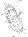
FIG. 1 is a perspective view of an embodiment of an underwater sensor apparatus in accordance with the present disclosure; -
FIG. 2 is a front view of an embodiment of an underwater sensor apparatus in accordance with the present disclosure; -
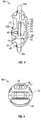
FIG. 3 is a rear view of an embodiment of an underwater sensor apparatus in accordance with the present disclosure; -
FIG. 4 is a side view of an embodiment of an underwater sensor apparatus in accordance with the present disclosure; -
FIG. 5 is a bottom view of an embodiment of an underwater sensor apparatus in accordance with the present disclosure; -
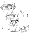
FIG. 6 is an exploded view of an embodiment of an underwater sensor apparatus in accordance with the present disclosure; -
FIG. 7 is a front view of an embodiment of an underwater sensor apparatus in accordance with the present disclosure -
FIG. 8 is a rear view of an embodiment of an underwater sensor apparatus in accordance with the present disclosure; -
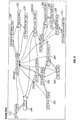
FIG. 9 is a flow diagram of a sequence of display screens of an underwater sensor apparatus in accordance with the present disclosure; -
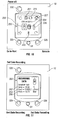
FIG. 10 is a detail view of an embodiment of an underwater sensor apparatus in accordance with the present disclosure showing an display screen; -
FIG. 11 is a detail view of an embodiment of an underwater sensor apparatus in accordance with the present disclosure showing an display screen; -
FIG. 12 is a detail view of an embodiment of an underwater sensor apparatus in accordance with the present disclosure showing an display screen; -
FIG. 13 is a detail view of an embodiment of an underwater sensor apparatus in accordance with the present disclosure showing an display screen; -
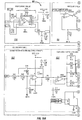
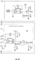
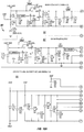
FIG. 14A is part one of a schematic diagram of an embodiment of an underwater sensor apparatus in accordance with the present disclosure; -
FIG. 14B is part two of a schematic diagram of an embodiment of an underwater sensor apparatus in accordance with the present disclosure; -
FIG. 15A is part one of a flow chart showing operation of an embodiment of an underwater sensor apparatus in accordance with the present disclosure; -
FIG. 15B is part two of a flow chart showing operation of an embodiment of an underwater sensor apparatus in accordance with the present disclosure; -
FIG. 16A is part one of a circuit diagram of a portion of a sensor board of an embodiment of an underwater sensor apparatus in accordance with the present disclosure; -
FIG. 16B is part two of a circuit diagram of a portion of a sensor board of an embodiment of an underwater sensor apparatus in accordance with the present disclosure; -
FIG. 16C is part three of a circuit diagram of a portion of a sensor board of an embodiment of an underwater sensor apparatus in accordance with the present disclosure; -
FIG. 17A is part one of a circuit diagram of an interface board of an embodiment of an underwater sensor apparatus in accordance with the present disclosure; -
FIG. 17B is part two of a circuit diagram of an interface board of an embodiment of an underwater sensor apparatus in accordance with the present disclosure; -
FIG. 17C is part three of a circuit diagram of an interface board of an embodiment of an underwater sensor apparatus in accordance with the present disclosure; -
FIG. 18A is part one of a circuit diagram of a portion of a sensor board including a main power supply, an auxiliary power supply, and a CPU of an embodiment of an underwater sensor apparatus in accordance with the present disclosure; -
FIG. 18B is part two of a circuit diagram of a portion of a sensor board including a main power supply, an auxiliary power supply, and a CPU of an embodiment of an underwater sensor apparatus in accordance with the present disclosure; and -
FIG. 18C is part three of a circuit diagram of a portion of a sensor board including a main power supply, an auxiliary power supply, and a CPU of an embodiment of an underwater sensor apparatus in accordance with the present disclosure. - In the following paragraphs, embodiments of the disclosure will be described in detail byway of example with reference to the attached drawings. Throughout this description, the exemplary embodiments and examples shown should be considered as exemplars, rather than as limitations on embodiments of the disclosure. As used herein, the "embodiments," "exemplary embodiments" or "embodiments of the disclosure" refer to any one of the embodiments described herein. Furthermore, reference to various feature(s) of the "embodiments," "exemplary embodiments or "embodiments of the disclosure" throughout this document does not mean that all claimed embodiments or methods must include the referenced feature(s).
- Referring first to
FIGS. 1-8 , exemplary embodiments of an underwater sensor apparatus will be described.Underwater sensor apparatus 10 comprises twohousing components jacket 14. Afirst housing component 12a houses thedisplay 16 and includeswindow 22 to allow visual access to the display orgraphical user interface 16 by the user of the apparatus.display 16 may be a liquid crystal display (LCD) or may use other suitable display technologies. Astylus 50 may be provided for user to interact with thedisplay 16 through the use ofmagnetic switches stylus 50 is used to activate magnetic switches 52 to input data, activate a system activity, activate a screen or otherwise navigate thedisplay 16.LED 54 emits light to signal, e.g., that the apparatus's power is on. Asecond housing component 12b is configured to house one or more sensors and/or probes used to collect and measure various underwater parameters, which will be described in more detail herein. - As best seen in
FIG. 6 , aninterface module 20 stands betweendisplay 16 andsensor board 24 and provides both a structural and electrical interconnection between the sensors and/or probes located withinhousing component 12b and the display located withinhousing component 12a. More particularly, graphical user interface ordisplay 16 is fastened to interfacemodule 20 usingscrews 19a-19c threaded throughstandoffs 21a-21c.Interface module 20 is, in turn, fastened tosensor board 24 viascrews standoffs First housing component 12a andsecond housing component 12b are attached by fastener assemblies including screws and O-rings display 16,interface module 20 and various sensors and/or probes securely held and sealed within thehousing components -
Endcap component 26 is a substantially hollow rounded end piece that connects to bothhousing components socket mechanism 28.Endcap component 26 also serves as an enclosure forbattery 30 and containsbattery contact 32. In exemplary embodiments, theunderwater sensor apparatus 10 is powered by two double AA batteries, which can be loaded and replaced without the use of tools.Endcap component 26 may be weighted to provide directional stability and control, making theunderwater sensor apparatus 10 easier and faster to deploy. Weighting may be accomplished by adding weight to the endcap end of the unit such that the device descends endcap end first. The batteries located in theendcap component 26 can provide such weighting. - The
second housing component 12b defines achannel 36 that extends substantially vertically through the back of the component. Each end of the channel may have a funnel-shapedportion 37.Channel 36 contains the access points 68for at least some of the apparatus's sensors and probes so that these components are protected from damage.Channel 36 has a self-flushing design that acts as a natural pump to provide the advantage of facilitating water flow on the apparatus' sensors and probes for improved data collection. The weight distribution ofhousing components underwater sensor apparatus 10 falls vertically when being submerged and maintains a vertical orientation when being pulled up out of the water. In this manner, as the device moves through the water, the amount of water flowing through the channel is increased for both data collection passes and for flushing purposes. More particularly, as the apparatus moves either up or down through the water, the water is constantly pushed throughchannel 36. Thus, new water is constantly replacing water at the level of each sensor so the sensors get data readings at every water level. This ensures accurate data readings, particularly for thetemperature sensor 70, which needs a constant rate of water flow to measure temperature accurately. It should be noted that the vertical orientation allows the user to measure the rate of fall by monitoring changes in pressure. Thus, the user can use flow measurements to correct problems relating to water flow rate that may occur with thetemperature sensor 70. - The fully assembled
housing components endcap component 26 fit snugly withinjacket 14, which serves to protect the housing and endcap components and the electronics and hardware therein.Jacket 14 may have any formation suitable to provide adequate protection for thehousing 12 and the components therein, and an exemplary configuration will now be described.Jacket 14 comprises top andbottom attachment portions aperture 40 suitable for threading and securing attachment mechanisms such as chain links or cable. The front section ofjacket 14 includes a roundedtop shell portion 42, a roundedbottom shell portion 44 andmiddle cross portion 46 to provide extra protection and support.Top shell portion 42 covers the top front ofhousing component 12a, andbottom shell portion 44 covers the bottom front ofhousing component 12b. Betweentop shell portion 42 andmiddle cross portion 46,jacket 14 defines afirst cutout 48 sized and shaped to allow the user easy access tomagnetic switches display 16.Jacket 14 defines asecond cutout 56 betweenmiddle cross portion 46 andbottom shell portion 44. The back ofjacket 14 defines a top and bottom cutout 60a, 60b sized to expose the top and bottom openings ofchannel 36. Center portion 62 of the back of thejacket 14 defines a series of alternatinglateral strips 64 andcutouts 66. This arrangement ofstrips 64 andcutouts 66 provides additional stability and support forhousing component 12b. - Referring to
FIG. 6 , some of the internal components ofunderwater sensor apparatus 10 will now be described. It should be noted that placement of the sensors and probes can vary considerably and provide many forms of data including but not limited to pressure, temperature, conductivity, depth, salinity, sound speed, dissolved oxygen, turbidity, chlorophyll, pH, nitrates, nitrites, carbon dioxide, water velocity, acoustic backscattering strength, fluorescence and water velocity. It should be noted that the embodiments discussed herein show exemplary configurations and many other arrangements are possible. Thesensor apparatus 10 comprisestemperature sensor 70, which is disposed inhousing component 12b and extends intochannel 36 through anaccess point 68 so that it can measure the temperature of the water when submerged.Temperature sensor 70 may be of any suitable type, e.g., a thermistor, which is one of the most accurate types of temperature sensors. A thermistor is an element composed of a material that exhibits a large change in resistance proportional to a small change in temperature. Thermistors usually have negative temperature coefficients, which means the resistance of the thermistor decreases as the temperature increases. - Also disposed within
housing component 12b areconductivity electrodes 74 andpressure sensor 20. In exemplary embodiments, conductivity electrodes are made of titanium to provide more robust conductivity, but they may be made of any suitable conductive material.Pressure cal module 72 is a circuit board that facilitates operative connection of sensors to theunderwater sensor apparatus 10 without the need for additional wires. Thepressure cal module 72 may be mounted flush to the housing, and wires from the sensors may soldered to the pressure cal module. The pressure cal module may contain pads to support some calibration resistors that are specific to the installed pressure sensor, and then passes the conditioned signals on to the main circuit board via a connector (not shown). Thus,housing components pressure cal module 72 facilitates their operational interconnection. - In an exemplary configuration,
conductivity electrodes 74 are located below thetemperature sensor 70. Theconductivity electrodes 74 extend out ofhousing component 12b intochannel 36 throughaccess points 68 so that they can measure the conductivity when submerged.Pressure sensor 76 is disposed within the bottom ofhousing component 12b and plugshole 78.Wires 77 extend through thehole 78 intohousing component 12b and are connected to pressurecal module 72. Thepressure sensor 76 is exposed to water via a hole (not shown) in the right inner side ofchannel 36, so thatpressure sensor 76 can make pressure readings. The underwater sensor apparatus also contains a central processing unit (CPU) 80, or controller, on which software is run to process the collected data. The CPU may be any form of controller or microprocessor. - In operation, the user prepares the
underwater sensor apparatus 10 for a cast by using thestylus 50, which may be a magnetic stylus having a magnetic tip, to program the apparatus to collect the desired water characteristics. These characteristics could include temperature, pressure, conductivity and depth, among others. The user first turns theunderwater sensor apparatus 10 on by activating one of themagnetic switches stylus 50.LED 54 will emit light to indicate that the apparatus is on. Next, the user again activates one of themagnetic switches stylus 50 to select the "Cast" icon on thedisplay 16, which may be waterproof. It should be noted that themagnetic stylus 50 and magnetic switches 52 may be used for any kind of data input and for navigating various screens on thedisplay 16. Magnetic switches are advantageous because they have no moving parts, can be used both in and out of the water and rarely fail in the field. - The
GPS 110 automatically provides the user with geographic data, including the exact position, date and time of the cast via thedisplay 16. Finally, the user selects the icon for starting data collection and lowers theunderwater sensor apparatus 10 into the water. This may be done by securing attachment mechanisms such as chain links or cable toaperture 40 oftop attachment portion 38a of theapparatus jacket 14. After attaching the cable or line, the device is lowered into the water. Typically the device is allowed to free-fall, although it is possible to control the descent speed by controlling the deployment of the line or cable. The device is allowed to descend to a predetermined depth or to the bottom depending on the test parameters. Once the bottom or desired depth is reached the device is retrieved by reeling in the line or cable. Once theunderwater sensor apparatus 10 is out of the water the user can view the data on thedisplay 16, as best seen inFIGS. 12 and 13 , or wirelessly download the data to a computer. - Referring to
FIGS. 6 and14A-C , the layout and operation of theunderwater sensor apparatus 10 will be described in more detail. It can be seen thatpressure sensor 20 and temperature sensor orthermistor probe 70 are operatively connected to pressurecal module 72, which, in turn, is operatively connected tosensor board 82. Thesensor board 82 is operatively connected to interfaceboard 84, which, in turn, is operatively connected to display 16.Battery 30 is connected to interfaceboard 84 viabattery contact 32. Interface board comprisesGPS capability 110 andtransceiver 112 to provide bluetooth capability. The bluetooth capability eliminates the need for various connectors and cables to start, program, review or download data.LED 54 is also located oninterface board 84.Sensor board 82 comprisespower supply 86, which provides power toCPU 80,recorder 88 andPI filter 92 to prevent supply noise from affecting the system. -
CPU 80 comprises analog-to-digital converter (ADC) 94 and digital-to-analog converter (DAC) 96. TheCPU 80 controls de-bugport 90 and receives data frompressure circuit 98 andtemperature circuit 100 upon those components receiving pressure and temperature data frompressure sensor 20 andtemperature probe 70, respectively. DAC 96 conductswaveform conditioning 102 and conductivity drive andscale selection 104.Conductivity electrodes 74 feed data intosensor board 82, which conductssignal selection 106 and signal amplification andconditioning 108 before feeding the conductivity data toADC 94 inCPU 80. Voltage references 114 are provided to thetemperature circuit 100 and thepressure circuit 98 and are used to conduct signal amplification andconditioning 108.Waveform conditioning 102, conductivity drive andscale selection 104,signal selection 106 and signal amplification andconditioning 108 are performed by conductivity block orcircuit 116. The waveform or frequency output may be arbitrary and could comprise sine waves. Several frequency simulations could be used and could be modulated to reduce capacitance. The conductivity block also measures current and phase information. One possible configuration of conductivity block is the six circuit design, as best seen inFIG. 14 . - After the
underwater sensor apparatus 10 boots up 2000, it reads theconfiguration parameters 2002 that are entered in by the user and computesDAC output waveforms 2004. Theunderwater sensor apparatus 10 then waits for the user to indicate the start ofdata acquisition mode 2006. Upon receiving the instruction to start data acquisition, theunderwater sensor apparatus 10 effects several steps to prepare for data acquisition. Thesesteps 2008 include calibrating analog-to-digital (ADC) converters, setting up and running data acquisition timers, setting initial resistor range and starting DAC waveform output. The sample accumulators may be reset 2010, and theunderwater sensor apparatus 10 will check the acquired data readings to determine if they correlate to the user requested readings in anaverage interval 2012. If the average interval is complete, theunderwater sensor apparatus 10 will check if there are any accumulatedreadings 2026. - If at least one reading is accumulated, the sample mean temperature, pressure, conductivity A and conductivity B will be calculated. At this stage, the
underwater sensor apparatus 10 will also compute the mean for all other requested parameters for diagnostic purposes and may collect sample statistics as well. If there are no accumulated readings, a bad sample will be generated 2028. Thenext steps 2032 may include recording either the accumulated reading or the bad sample to an internal recorder, outputting the sample on thedisplay 16 and/or transmitting the sample via the underwater sensor apparatus's bluetooth capability. Theunderwater sensor apparatus 10 will then determine if the user requested to endsampling 2034 and, if so, will complete data acquisition. If the user has not requested to end sampling, theunderwater sensor apparatus 10 will continue data acquisition by reverting to step 2010 and reset sample accumulators. - If, after
step 2012, the averaging interval is not complete, theunderwater sensor apparatus 10 will read more samples fromtemperature sensor 70,conductivity electrode 74,pressure sensors underwater sensor apparatus 10 will then check the readings to determine if the measurements were done in the requestedrange 2018. If they were done correctly, the last reading will be accumulated 2020. If they were done in the wrong range, a new range will be selected, the DAC waveform will be re-programmed and the range resistors may be switched. Then theunderwater sensor apparatus 10 will revert to step 2012 and again determine whether the acquired readings correspond to the requested readings. -
FIGS. 14A-B and16A-18C are system block and circuit diagrams that show the electrical connections of various sections of the underwater sensor apparatus. More particularly,FIGS. 14A-B is a system block diagram showing an overview of the electrical connections of an embodiment of an underwater sensor apparatus.FIGS. 16A-C is a schematic circuit diagram showing a portion ofsensor board 82.FIGS. 17A-C is a schematic circuit diagram showinginterface board 84.FIGS. 18A-C is a schematic circuit diagram showing another portion ofsensor board 82 includingmain power supply 86,auxiliary power supply 87 andCPU 80. - With reference to
FIGS. 9-13 , embodiments of andisplay 16 and its operation will now be described in more detail. Thedisplay 16 can display icons and/or text to guide the user through the operating system.FIG. 9 is a flow chart showing some of the different paths the user can take to view different screens on the display. Each screen is designed for a specific system function. When theunderwater sensor apparatus 10 is turned on, as described above, a start screen /logo screen 210 is displayed.Start screen 210 may display brand information such as words or designs showing the name of the manufacturer of the underwater sensor apparatus or a trademark associated with the product. - The first screen with operational information on
display 16 ishome screen 220, which displays a menu of icons offering different functions. As shown inFIG. 10 , in exemplary embodiments the menu ofhome screen 220 includes three branches and each branch is represented by an icon on the display screen. The first branch is a data collection branch that activates the GPS and starts data collection. The icon representing the data collection branch may be referred to as the "Cast"icon 222. The second branch, represented by the "Review"icon 224, provides a pathway to review collected data and displays the data in both text and graph form. The third branch is a system information branch having asystem icon 226, which may be represented by a letter "i" and displays information about the underwater sensor apparatus.Home screen 220 may also include various other icons to indicate parameters such as arecorder status indicator 221 showing how full the recorder is with data, abattery life indicator 223, aBluetooth indicator 225 showing whether Bluetooth is on or off, and the systemserial number 227 and to provide the ability to move to other screens. A "House" icon indicates that the user is on thehome screen 220. - Typical use would include first activating the GPS and data collection using the
Cast icon 222 and then viewing the collected data using theReview icon 224. When the desired icon is selected, pressing the "execute"button 52b will activate the command associated with the selected icon. Pushing the "execute"button 52b with thecast icon 222 selected will activate a "Wait for GPS Before Cast"screen 230. Pushing the "execute"button 52b with thereview icon 224 selected will activate a DataFile review screen 240, and pushing the "execute"button 52b with thesystem icon 226 selected will activate aSystem Status screen 250. Each of these screens are discussed in turn below. - The "Wait for GPS Before Cast"
screen 230 allows the user to prepare the system for cast or deployment by displaying real-time data from the GPS for determining the accuracy of the displayed location. The Wait for GPS BeforeCast screen 230 may show the date and time and GPS position information in the form of latitude and longitude numbers. In exemplary embodiments, a circle icon (not shown) may change color with different colors indicating the quality of the location or GPS position. For example, a green light may indicate a good GPS position, a red light may indicate no GPS position, and a yellow light may indicate a satisfactory GPS position. A GPS quality indicator may also include varying numbers of bars of varying lengths. The user pushesbutton 52b to record the GPS location before casting theunderwater sensor apparatus 10, and thebutton 52b is pressed again to start collecting data such as conductivity, temperature and pressure. - The
underwater sensor apparatus 10 is then ready for deployment and aData Acquisition screen 260 is displayed. This screen indicates that data is being recorded onboard theunderwater sensor apparatus 10. As shown inFIG. 11 , theData Acquisition screen 260 shows temperature, conductivity and pressure readings beneath large letters indicating that the device is recording data. At this point, theunderwater sensor apparatus 10 may be secured with a line and tossed into the water. In exemplary embodiments, the screen is dimmable and may dim after deployment to conserve power. Theunderwater sensor apparatus 10 will measure and record data as it descends through the water, including, forexample temperature data 262,conductivity data 264, sound speed data, salinity data, andpressure data 266. It should be noted that parameters such as temperature and conductivity are measured while parameters such as salinity and sound speed are typically calculated using oceanographic formulas. Once the device has reached the bottom of the body of water, it can be pulled back up using the attached line, and it will continue measuring and recording data as it ascends back up to the surface of the water. Upon retrieval of theunderwater sensor apparatus 10, the user may push any button to activate the display and then push any button a second time to end the cast, close the data file, and start the GPS. - A second GPS location is then recorded at the end of the cast. This is particularly advantageous where the
underwater sensor apparatus 10 has been cast from a moving boat. A "Wait for GPS after Cast"screen 270 appears next. This screen is similar to the Wait for GPS BeforeCast screen 230 described above in that it displays location information such as latitude and longitude numbers, and indicates GPS signal quality by, e.g., a varying number and length of signal strength bars. The user pushesbutton 52b after the cast to record the location and can decide whether or not to wait for a good GPS position. As discussed above, a color-coded indicator uses green, yellow and red to indicate the quality of the GPS position. Pushingbutton 52a from this screen will return the user toHome Screen 220. - Data
File review screen 240 appears when the user selects thereview icon 224 and pushesbutton 52b. As shown inFIG. 12 , the DataFile review screen 240 displays the most recent data from the device's recorder. In exemplary embodiments, the data collected by the device's sensors are stored every 0.2 seconds (5 Hz). This screen also may indicate the start time and location of the cast, including thelatitude 242 andlongitude 244 displayed in decimal degrees, as well as themaximum depth 246 the device reached during the cast. When the DataFile review screen 240 is accessed from thehome screen 220, the most recent data on the recorder is displayed. The user can access older data files by usingbutton 52a.Pressing button 52b will advance the user to theTemperature Profile screen 280. - In exemplary embodiments, a
Temperature Profile screen 280 provides information relating to the temperature of the water being measured. This may include a graph that can show various parameters including a plot of temperature versus depth with the temperature statistics typically displayed in degrees Celsius, as well as the minimum, maximum and average temperature. The line on the graph may plot the average of the cast temperature measurements taken at each depth, including those taken during both the ascent and descent of theunderwater sensor apparatus 10. In exemplary embodiments, the depth shown on the Temperature Profile screen is the extent of the plot of the graph, but could be other depths such as the maximum depth of the cast. The user can advance to aConductivity Profile screen 290 by pressingbutton 52b. - Referring to
FIG. 13 , aConductivity Profile screen 290 will be described. In exemplary embodiments, aConductivity Profile screen 290 provides information relating to the conductivity of the water being measured. The information may include agraph 292 that plots conductivity versus depth with the conductivity statistics displayed in microSiemens per centimeter, as well as the minimum, maximum and average conductivity. In exemplary embodiments, the depth shown on theConductivity Profile screen 290 is the extent of the plot of the graph, but could be other depths such as the maximum depth of the cast. The line on the graph may plot the minimum 291, maximum 293, and average 294 of the cast conductivity measurements taken at each depth, including those taken during both the ascent and descent of theunderwater sensor apparatus 10. By pushingbutton 52b, the user can proceed toSalinity Profile screen 300. - The
Salinity Profile screen 300 may provide salinity information including statistics displayed in parts per thousand. The salinity information may also include a graph that plots salinity versus depth. The line on the graph may plot the average of the cast salinity measurements taken at each depth, including those taken during both the ascent and descent of theunderwater sensor apparatus 10. In exemplary embodiments, the depth shown on theSalinity Profile screen 300 is the extent of the plot of the graph, but could be other depths such as the maximum depth of the cast.Pressing button 52a will load the previous data file, andpressing button 52b will advance to the SoundSpeed Profile screen 310. - The Sound
Speed Profile screen 310 provides sound speed statistics, typically displayed in meters per second and including the average, minimum and maximum sound speed measured. The sound speed information may be presented in graph form with the plot line showing the average of the cast sound speed measurements taken at each depth, including those taken during both the ascent and descent of theunderwater sensor apparatus 10. The depth shown on the SoundSpeed Profile screen 310 is typically the extent of the plot of the graph, but could be other depths such as the maximum depth of the cast. The user can load the previous data file by pushing button 52 and can advance to theFile Review screen 310 by pushingbutton 52b. - The
System Status screen 250 displays basic information about the underwater sensor apparatus as well as date and time information. In exemplary embodiments, the date and time are shown in Coordinated Universal Time (UTC), also known as Greenwich Mean Time (GMT) or Zulu time. The underwater sensor apparatus periodically receives a correct time from the onboard GPS and updates the date and time. A Battery Health indicator displays the percentage of battery life remaining, and a Recorder Available indicator displays the percentage of data recorder space remaining. Exemplary embodiments may also include the date and time the underwater sensor apparatus was last used. ASystem Information screen 320 can be viewed by pressingbutton 52b and may provide general information such as the internet url and contact information for the manufacturer of the device, a phone number for customer service, and other information about the device system and software.Pressing button 52b from theSystem Information screen 320 will take the user to aTSI Logo screen 350. - From the
System Status screen 250, pressingbutton 52a will take the user to theSensor Display screen 330.Sensor Display screen 330 provides a real time display for a sensor status check and the point measurements for the different parameters such as temperature, conductivity and pressure without recording the data to the system. Finally, when the user is finished, theunderwater sensor apparatus 10 may be powered off by pressing button 52c. This leads to ablank Off screen 340. From theOff screen 340, the user can go to theStart screen 210 by pressing any ofbuttons - While embodiments of the disclosure have been described above, it will be apparent to one skilled in the art that various changes and modifications may be made. Although illustrative embodiments are described hereinabove, it will be evident to one skilled in the art that various changes and modifications may be made therein without departing from the claims. It is intended in the appended claims to cover all such changes and modifications that fall within the scope of the claims.
Claims (12)
- An apparatus (10) for monitoring and collecting water environmental data, comprising:a submersible housing (12) comprising a first housing component (12a), forming a front housing component, and a second housing component (12b), forming a back housing component, the first housing component (12a) and the second housing component (12b) having a weight distribution that ensures the apparatus (10) maintains a vertical orientation when moving up or down in water;the second housing component (12b) defining a channel (36) extending substantially vertically through the back of said second housing component (12b), the channel (36) being oriented such that water flows through the channel (36) when the apparatus (10) is submerged and moving up or down;one or more sensors (20, 70, 74, 76) for collecting selected water environmental data, the sensors (20, 70, 74, 76) being mounted to the housing (12), wherein the second housing component (12b) houses the one or more sensors (20, 70, 74, 76);a controller (80) for controlling operations of the one or more sensors (20, 70, 74, 76), the controller (80) being disposed within the housing (12) and operatively connected to the one or more sensors (20, 70, 74, 76); and a graphical user interface (16) mounted to the housing (12) for displaying the water environmental data, wherein the first housing component (12a) houses the graphical user interface (16);a GPS (110) receiver disposed within the housing (12); anda transceiver (112) disposed within the housing (12) for sending the water environmental data to a remote data collection system.
- The apparatus (10) of claim 1 wherein the channel (36) defines one or more access points (68) and one or more of the sensors (20, 70, 74, 76) extend into the channel (36) through the access points (68).
- The apparatus (10) of claim 1 wherein the channel (36) has a first end and a second end and each end is substantially funnel-shaped.
- The apparatus (10) of claim 1 further comprising a jacket (14) covering the submersible housing (12).
- The apparatus (10) of claim 1 wherein the GPS (110) collects geographical data and sends at least some of the geographical data through the transceiver (112) to a remote data collection system.
- The apparatus (10) of claim 1 further comprising an interface module (20) sealed within the housing components (12a, 12b) providing an electrical interconnection between the sensors (20, 70, 74, 76) and the graphical user interface (16).
- The apparatus (10) of claim 1 further comprising a weighted endcap component (26) fixedly attached to the submersible housing (12) at a bottom portion thereof.
- The apparatus (10) of claim 1 wherein the sensors (20, 70, 74, 76) include one or more of: a temperature sensor (70), a conductivity electrode (74) and a pressure sensor (76).
- The apparatus (10) of claim 1 further comprising a pressure cal module (72) operatively connecting the one or more sensors (20, 70, 74, 76) to the controller (80).
- The apparatus (10) of claim 1 further comprising one or more magnetic switches (52a, 52b, 52c) included inside the submersible housing (12), the one or more magnetic switches (52a, 52b, 52c) designed to be activated by a stylus (50).
- The apparatus (10) of claim 7 wherein the endcap component (26) is weighted to maintain the apparatus (10) in an orientation substantially vertical when being lowered or raised in water.
- The apparatus (10) of claim 1 wherein the apparatus (10) is designed as an underwater sensor device.
Applications Claiming Priority (2)
| Application Number | Priority Date | Filing Date | Title |
|---|---|---|---|
| US31123010P | 2010-03-05 | 2010-03-05 | |
| PCT/US2011/027244 WO2011109740A2 (en) | 2010-03-05 | 2011-03-04 | Underwater sensor apparatus |
Publications (3)
| Publication Number | Publication Date |
|---|---|
| EP2542923A2 EP2542923A2 (en) | 2013-01-09 |
| EP2542923A4 EP2542923A4 (en) | 2016-06-15 |
| EP2542923B1 true EP2542923B1 (en) | 2020-06-03 |
Family
ID=44530151
Family Applications (1)
| Application Number | Title | Priority Date | Filing Date |
|---|---|---|---|
| EP11751444.8A Active EP2542923B1 (en) | 2010-03-05 | 2011-03-04 | Underwater sensor apparatus |
Country Status (6)
| Country | Link |
|---|---|
| US (1) | US8272262B2 (en) |
| EP (1) | EP2542923B1 (en) |
| CN (1) | CN102884451B (en) |
| AU (1) | AU2011222560B2 (en) |
| CA (1) | CA2792165C (en) |
| WO (1) | WO2011109740A2 (en) |
Families Citing this family (38)
| Publication number | Priority date | Publication date | Assignee | Title |
|---|---|---|---|---|
| US9188512B2 (en) | 2011-05-20 | 2015-11-17 | Woods Hole Oceanographic Institution | Aquatic sample analysis system |
| WO2013052747A2 (en) * | 2011-10-07 | 2013-04-11 | Teledyne Instruments, Inc. | Methods and systems for configuring sensor acquisition based on pressure steps |
| FR2984398B1 (en) * | 2011-12-20 | 2014-01-03 | Total Sa | METHOD FOR MONITORING A SUBMARINE SITE |
| CN102589531B (en) * | 2012-01-05 | 2014-06-18 | 天津市水利科学研究院 | Underwater topography measurement boat as well as manufacturing method and measurement method |
| US9507562B2 (en) | 2013-08-21 | 2016-11-29 | Navico Holding As | Using voice recognition for recording events |
| US10251382B2 (en) * | 2013-08-21 | 2019-04-09 | Navico Holding As | Wearable device for fishing |
| WO2015094793A2 (en) * | 2013-12-19 | 2015-06-25 | Chevron U.S.A. Inc. | Underwater vehicle and sensor |
| CN103728427A (en) * | 2013-12-19 | 2014-04-16 | 谢虹 | Miniature water quality detector |
| CA2962278C (en) * | 2014-02-04 | 2023-05-02 | Lost Bird Project, Inc. | Method, apparatus and system for obtaining and monitoring environmental data |
| CN103910053B (en) * | 2014-04-24 | 2017-03-22 | 珠江水利委员会珠江水利科学研究院 | Unmanned observation control ship and unmanned observation control system |
| CN104007455A (en) * | 2014-06-09 | 2014-08-27 | 武汉大学 | Waterproof GPS device suitable for water area working |
| US10429369B2 (en) | 2014-11-10 | 2019-10-01 | In-Situ, Inc. | Integrated user interface for status and control of a submersible multi-parameter sonde |
| US11000021B2 (en) | 2015-02-20 | 2021-05-11 | Navico Holding As | Castable sensor device |
| US20160245649A1 (en) * | 2015-02-20 | 2016-08-25 | Navico Holding As | Castable Sensor Device |
| TWI588815B (en) * | 2015-06-01 | 2017-06-21 | 仁寶電腦工業股份有限公司 | Display parameter adjustment method and electronic device using the same |
| US9836129B2 (en) | 2015-08-06 | 2017-12-05 | Navico Holding As | Using motion sensing for controlling a display |
| AU2017232651A1 (en) | 2016-03-18 | 2018-10-04 | ConnectedYard, Inc. | Chemical monitoring devices and methods |
| DE102016003926B4 (en) * | 2016-03-31 | 2018-05-09 | Bundesrepublik Deutschland, vertr. durch das Bundesministerium der Verteidigung, vertr. durch das Bundesamt für Ausrüstung, Informationstechnik und Nutzung der Bundeswehr | Underwater probe |
| CN106019317B (en) * | 2016-05-17 | 2017-12-08 | 滨州学院 | A kind of GPS receivers for the mapping that suspended for water body |
| CN106019316B (en) * | 2016-05-18 | 2017-11-03 | 滨州学院 | The maneuverable GPS receivers of one kind tool and its application method |
| TWI607929B (en) * | 2016-07-22 | 2017-12-11 | Dwtek Co Ltd | Underwater transfer tank device with coupling unit |
| US10948577B2 (en) | 2016-08-25 | 2021-03-16 | Navico Holding As | Systems and associated methods for generating a fish activity report based on aggregated marine data |
| US10466891B2 (en) | 2016-09-12 | 2019-11-05 | Apple Inc. | Special lock mode user interface |
| US10719077B2 (en) | 2016-10-13 | 2020-07-21 | Navico Holding As | Castable sonar devices and operations in a marine environment |
| AU2017372870B2 (en) * | 2016-12-06 | 2020-08-13 | Ysi, Inc. | Method for compensating for venturi effects on pressure sensors in moving water |
| EP3739318B1 (en) * | 2016-12-15 | 2024-11-13 | INGU Solutions Inc. | Sensor device, systems, and methods for identifying leaks in a fluid conduit |
| CN106768458A (en) * | 2017-03-03 | 2017-05-31 | 云南坤发环境科技有限公司 | A kind of deep water temperature measuring set |
| EP3602024A4 (en) | 2017-03-21 | 2020-11-18 | Hayward Industries, Inc. | SYSTEMS AND PROCEDURES FOR HYGIENIZATION OF SWIMMING POOL AND SPA WATER |
| CN107421589A (en) * | 2017-08-23 | 2017-12-01 | 曾志 | A kind of small data shows bathythermograph |
| FR3082183B1 (en) * | 2018-06-08 | 2020-06-05 | Ecole Nationale Superieure De Techniques Avancees Bretagne | METHOD AND SYSTEM FOR ACTIVATING AND SETTING A TIMER FOR USE IN AN UNDERWATER ENVIRONMENT. |
| US10969941B2 (en) * | 2018-09-28 | 2021-04-06 | Apple Inc. | Underwater user interface |
| TWI670471B (en) * | 2018-12-14 | 2019-09-01 | 國家中山科學研究院 | Photoelectric monitoring distance measuring device |
| CN110987006B (en) * | 2019-12-02 | 2023-07-21 | 中国海洋大学 | Ocean observation automatic test system and test method based on SOPC technology |
| US12007512B2 (en) | 2020-11-30 | 2024-06-11 | Navico, Inc. | Sonar display features |
| US11893212B2 (en) | 2021-06-06 | 2024-02-06 | Apple Inc. | User interfaces for managing application widgets |
| US20240151528A1 (en) * | 2022-11-04 | 2024-05-09 | Cciwadr, Llc | Watershed Autonomous Robotic Data Recorders for Mapping Subsurface Topography and Obtaining Water Quality Data For Bodies of Water |
| CN115979260B (en) * | 2023-02-24 | 2023-06-02 | 北京大学 | Bionic navigation system, method, equipment and computer storage medium |
| US12474317B2 (en) * | 2023-04-06 | 2025-11-18 | United States Of America As Represented By The Secretary Of The Navy | Mardan sub-surface sensor housing for remote underwater vehicle deployment and recovery |
Family Cites Families (21)
| Publication number | Priority date | Publication date | Assignee | Title |
|---|---|---|---|---|
| US4122428A (en) * | 1976-11-22 | 1978-10-24 | Morrow Jr Ray E | Marine detection apparatus |
| JPH0623752B2 (en) | 1989-04-21 | 1994-03-30 | 株式会社戸上電機製作所 | Equipment for measuring salt concentration in sand |
| JPH089636Y2 (en) * | 1990-04-09 | 1996-03-21 | 株式会社堀場製作所 | Ion concentration measuring device |
| US5283767A (en) | 1992-02-27 | 1994-02-01 | Mccoy Kim | Autonomous oceanographic profiler |
| JP3010522B2 (en) | 1995-08-03 | 2000-02-21 | 沖電気工業株式会社 | Ocean sensor device |
| US5578751A (en) * | 1995-12-08 | 1996-11-26 | The United States Of America As Represented By The Secretary Of The Navy | Oceanographic sensor suite wet well system |
| US5821405A (en) * | 1996-02-29 | 1998-10-13 | Hydrolab Corporation | Modular water quality apparatus and method |
| US6456197B1 (en) | 1998-03-25 | 2002-09-24 | Fmc Technologies, Inc. | Oil-in-water detector buoy arrangement |
| US6111249A (en) * | 1998-07-17 | 2000-08-29 | Hydrolab Corporation | Submergible optical sensor housing with protective shutter and methods of operation and manufacture |
| WO2000039533A1 (en) * | 1998-12-23 | 2000-07-06 | Flytec Ag | Water-tight measurement device |
| US6536272B1 (en) * | 1999-08-06 | 2003-03-25 | University Of Miami | Water monitoring, data collection, and transmission module |
| US7239577B2 (en) * | 2002-08-30 | 2007-07-03 | Pgs Americas, Inc. | Apparatus and methods for multicomponent marine geophysical data gathering |
| CN2751309Y (en) * | 2004-12-22 | 2006-01-11 | 中国科学院南海海洋研究所 | A Current Gauge with Station Position, Depth Measurement and Wireless Communication Functions |
| US7343261B1 (en) * | 2005-02-01 | 2008-03-11 | Curtis Kell | Underwater sensor transmitter probe |
| CA2597917C (en) * | 2005-02-15 | 2012-07-24 | In-Situ, Inc. | Submersible probe apparatus for aqueous environment monitoring with new cam-twist interconnect, liquid barrier and battery pack |
| US8048372B1 (en) * | 2005-08-05 | 2011-11-01 | Oceanit Laboratories, Inc. | Sensor system for real-time bioluminescence signature determination |
| US7380435B1 (en) * | 2005-11-07 | 2008-06-03 | Florida State University Research Foundation | Lab animal tracker and deterministic shocker |
| WO2008018929A2 (en) * | 2006-04-28 | 2008-02-14 | Rowan University | Interactive mobile aquatic probing and surveillace system |
| US7380453B1 (en) * | 2006-09-16 | 2008-06-03 | Advanced Design Consulting Usa, Inc | Undersea data logging device with automated data transmission |
| ATE530902T1 (en) | 2007-02-21 | 2011-11-15 | Marco Marcelli | DISPOSABLE DISPOSABLE PROBE FOR TEMPERATURE AND FLUORESCENCE MEASUREMENTS IN UNDER SEA ENVIRONMENTS |
| CN101592649A (en) * | 2009-05-27 | 2009-12-02 | 深圳市华测检测技术股份有限公司 | But a kind of remote-control self-navigation water quality sampling and analyzing device |
-
2011
- 2011-03-04 EP EP11751444.8A patent/EP2542923B1/en active Active
- 2011-03-04 CA CA2792165A patent/CA2792165C/en active Active
- 2011-03-04 AU AU2011222560A patent/AU2011222560B2/en active Active
- 2011-03-04 CN CN201180022592.1A patent/CN102884451B/en active Active
- 2011-03-04 US US13/041,046 patent/US8272262B2/en active Active
- 2011-03-04 WO PCT/US2011/027244 patent/WO2011109740A2/en not_active Ceased
Non-Patent Citations (1)
| Title |
|---|
| None * |
Also Published As
| Publication number | Publication date |
|---|---|
| AU2011222560B2 (en) | 2014-04-17 |
| AU2011222560A1 (en) | 2012-09-27 |
| US8272262B2 (en) | 2012-09-25 |
| CN102884451A (en) | 2013-01-16 |
| CN102884451B (en) | 2015-08-12 |
| CA2792165C (en) | 2015-01-27 |
| EP2542923A2 (en) | 2013-01-09 |
| EP2542923A4 (en) | 2016-06-15 |
| US20110214500A1 (en) | 2011-09-08 |
| CA2792165A1 (en) | 2011-09-09 |
| WO2011109740A2 (en) | 2011-09-09 |
| WO2011109740A3 (en) | 2011-12-15 |
Similar Documents
| Publication | Publication Date | Title |
|---|---|---|
| CA2792165C (en) | Underwater sensor apparatus | |
| EP3042161B1 (en) | Resistive liquid level/temperature sensor and transmitter | |
| KR101542546B1 (en) | Apparatus for observation underground water | |
| US20080243509A1 (en) | Speech module | |
| US6928862B1 (en) | Method of monitoring dual-phase liquid and interface levels | |
| US20070147173A1 (en) | Simplicity sonic depth finder for fishing | |
| CA2161615C (en) | Electric conductivity measurement circuit and probe | |
| CA2979081A1 (en) | Aquatic visual data collector | |
| US7238263B2 (en) | Corrosion tester | |
| EP1962089B1 (en) | Expendable launchable probe for temperature and fluorescence measurements of the undersea environment | |
| EP0809787B1 (en) | Depth sensing expendable oceanographic probe with no extra data channel | |
| WO2004104974A8 (en) | System and method for testing displays | |
| CN101846515A (en) | Device capable of quickly getting depth profile data of sea water temperature | |
| CN201724759U (en) | Device capable of rapidly acquiring seawater temperature-depth cross-sectional data | |
| US6934657B1 (en) | Method, system, and device for graphically presenting water temperature data | |
| US7380453B1 (en) | Undersea data logging device with automated data transmission | |
| US20030023397A1 (en) | Portable, digital storage-tank measurement device | |
| Hannon | New developments in expendable oceanographic sensors and data acquisition systems | |
| US20250264364A1 (en) | Liquid temperature sensor apparatus | |
| Bucca et al. | Oceanographic measurements with microprocessors | |
| CA2206055C (en) | Depth sensing expendable oceanographic probes | |
| Marouchos et al. | A system for correcting ADCP heading on moorings at high latitudes | |
| CN107421589A (en) | A kind of small data shows bathythermograph | |
| Williams | Development of an acoustic current meter: Lessons taught by clients and colleagues | |
| Birch | Sensors and systems for Cumulus Surface Flux Measurement Programme |
Legal Events
| Date | Code | Title | Description |
|---|---|---|---|
| PUAI | Public reference made under article 153(3) epc to a published international application that has entered the european phase |
Free format text: ORIGINAL CODE: 0009012 |
|
| 17P | Request for examination filed |
Effective date: 20121004 |
|
| AK | Designated contracting states |
Kind code of ref document: A2 Designated state(s): AL AT BE BG CH CY CZ DE DK EE ES FI FR GB GR HR HU IE IS IT LI LT LU LV MC MK MT NL NO PL PT RO RS SE SI SK SM TR |
|
| DAX | Request for extension of the european patent (deleted) | ||
| RIC1 | Information provided on ipc code assigned before grant |
Ipc: G01C 13/00 20060101ALI20160120BHEP Ipc: G01D 11/24 20060101ALI20160120BHEP Ipc: G01N 1/12 20060101ALI20160120BHEP Ipc: G01N 33/18 20060101AFI20160120BHEP |
|
| REG | Reference to a national code |
Ref country code: DE Ref legal event code: R079 Ref document number: 602011067137 Country of ref document: DE Free format text: PREVIOUS MAIN CLASS: G01V0009000000 Ipc: G01N0033180000 |
|
| A4 | Supplementary search report drawn up and despatched |
Effective date: 20160513 |
|
| RIC1 | Information provided on ipc code assigned before grant |
Ipc: G01C 13/00 20060101ALI20160509BHEP Ipc: G01N 1/12 20060101ALI20160509BHEP Ipc: G01N 33/18 20060101AFI20160509BHEP Ipc: G01D 11/24 20060101ALI20160509BHEP |
|
| STAA | Information on the status of an ep patent application or granted ep patent |
Free format text: STATUS: EXAMINATION IS IN PROGRESS |
|
| 17Q | First examination report despatched |
Effective date: 20180503 |
|
| GRAP | Despatch of communication of intention to grant a patent |
Free format text: ORIGINAL CODE: EPIDOSNIGR1 |
|
| STAA | Information on the status of an ep patent application or granted ep patent |
Free format text: STATUS: GRANT OF PATENT IS INTENDED |
|
| GRAJ | Information related to disapproval of communication of intention to grant by the applicant or resumption of examination proceedings by the epo deleted |
Free format text: ORIGINAL CODE: EPIDOSDIGR1 |
|
| STAA | Information on the status of an ep patent application or granted ep patent |
Free format text: STATUS: EXAMINATION IS IN PROGRESS |
|
| GRAP | Despatch of communication of intention to grant a patent |
Free format text: ORIGINAL CODE: EPIDOSNIGR1 |
|
| STAA | Information on the status of an ep patent application or granted ep patent |
Free format text: STATUS: GRANT OF PATENT IS INTENDED |
|
| INTG | Intention to grant announced |
Effective date: 20191129 |
|
| INTC | Intention to grant announced (deleted) | ||
| INTG | Intention to grant announced |
Effective date: 20191219 |
|
| GRAS | Grant fee paid |
Free format text: ORIGINAL CODE: EPIDOSNIGR3 |
|
| GRAA | (expected) grant |
Free format text: ORIGINAL CODE: 0009210 |
|
| STAA | Information on the status of an ep patent application or granted ep patent |
Free format text: STATUS: THE PATENT HAS BEEN GRANTED |
|
| AK | Designated contracting states |
Kind code of ref document: B1 Designated state(s): AL AT BE BG CH CY CZ DE DK EE ES FI FR GB GR HR HU IE IS IT LI LT LU LV MC MK MT NL NO PL PT RO RS SE SI SK SM TR |
|
| REG | Reference to a national code |
Ref country code: GB Ref legal event code: FG4D |
|
| REG | Reference to a national code |
Ref country code: CH Ref legal event code: EP Ref country code: AT Ref legal event code: REF Ref document number: 1277530 Country of ref document: AT Kind code of ref document: T Effective date: 20200615 |
|
| REG | Reference to a national code |
Ref country code: DE Ref legal event code: R096 Ref document number: 602011067137 Country of ref document: DE |
|
| REG | Reference to a national code |
Ref country code: LT Ref legal event code: MG4D |
|
| PG25 | Lapsed in a contracting state [announced via postgrant information from national office to epo] |
Ref country code: GR Free format text: LAPSE BECAUSE OF FAILURE TO SUBMIT A TRANSLATION OF THE DESCRIPTION OR TO PAY THE FEE WITHIN THE PRESCRIBED TIME-LIMIT Effective date: 20200904 Ref country code: NO Free format text: LAPSE BECAUSE OF FAILURE TO SUBMIT A TRANSLATION OF THE DESCRIPTION OR TO PAY THE FEE WITHIN THE PRESCRIBED TIME-LIMIT Effective date: 20200903 Ref country code: FI Free format text: LAPSE BECAUSE OF FAILURE TO SUBMIT A TRANSLATION OF THE DESCRIPTION OR TO PAY THE FEE WITHIN THE PRESCRIBED TIME-LIMIT Effective date: 20200603 Ref country code: LT Free format text: LAPSE BECAUSE OF FAILURE TO SUBMIT A TRANSLATION OF THE DESCRIPTION OR TO PAY THE FEE WITHIN THE PRESCRIBED TIME-LIMIT Effective date: 20200603 Ref country code: SE Free format text: LAPSE BECAUSE OF FAILURE TO SUBMIT A TRANSLATION OF THE DESCRIPTION OR TO PAY THE FEE WITHIN THE PRESCRIBED TIME-LIMIT Effective date: 20200603 |
|
| REG | Reference to a national code |
Ref country code: NL Ref legal event code: MP Effective date: 20200603 |
|
| PG25 | Lapsed in a contracting state [announced via postgrant information from national office to epo] |
Ref country code: HR Free format text: LAPSE BECAUSE OF FAILURE TO SUBMIT A TRANSLATION OF THE DESCRIPTION OR TO PAY THE FEE WITHIN THE PRESCRIBED TIME-LIMIT Effective date: 20200603 Ref country code: RS Free format text: LAPSE BECAUSE OF FAILURE TO SUBMIT A TRANSLATION OF THE DESCRIPTION OR TO PAY THE FEE WITHIN THE PRESCRIBED TIME-LIMIT Effective date: 20200603 Ref country code: BG Free format text: LAPSE BECAUSE OF FAILURE TO SUBMIT A TRANSLATION OF THE DESCRIPTION OR TO PAY THE FEE WITHIN THE PRESCRIBED TIME-LIMIT Effective date: 20200903 Ref country code: LV Free format text: LAPSE BECAUSE OF FAILURE TO SUBMIT A TRANSLATION OF THE DESCRIPTION OR TO PAY THE FEE WITHIN THE PRESCRIBED TIME-LIMIT Effective date: 20200603 |
|
| REG | Reference to a national code |
Ref country code: AT Ref legal event code: MK05 Ref document number: 1277530 Country of ref document: AT Kind code of ref document: T Effective date: 20200603 |
|
| PG25 | Lapsed in a contracting state [announced via postgrant information from national office to epo] |
Ref country code: NL Free format text: LAPSE BECAUSE OF FAILURE TO SUBMIT A TRANSLATION OF THE DESCRIPTION OR TO PAY THE FEE WITHIN THE PRESCRIBED TIME-LIMIT Effective date: 20200603 Ref country code: AL Free format text: LAPSE BECAUSE OF FAILURE TO SUBMIT A TRANSLATION OF THE DESCRIPTION OR TO PAY THE FEE WITHIN THE PRESCRIBED TIME-LIMIT Effective date: 20200603 |
|
| PG25 | Lapsed in a contracting state [announced via postgrant information from national office to epo] |
Ref country code: EE Free format text: LAPSE BECAUSE OF FAILURE TO SUBMIT A TRANSLATION OF THE DESCRIPTION OR TO PAY THE FEE WITHIN THE PRESCRIBED TIME-LIMIT Effective date: 20200603 Ref country code: SM Free format text: LAPSE BECAUSE OF FAILURE TO SUBMIT A TRANSLATION OF THE DESCRIPTION OR TO PAY THE FEE WITHIN THE PRESCRIBED TIME-LIMIT Effective date: 20200603 Ref country code: CZ Free format text: LAPSE BECAUSE OF FAILURE TO SUBMIT A TRANSLATION OF THE DESCRIPTION OR TO PAY THE FEE WITHIN THE PRESCRIBED TIME-LIMIT Effective date: 20200603 Ref country code: RO Free format text: LAPSE BECAUSE OF FAILURE TO SUBMIT A TRANSLATION OF THE DESCRIPTION OR TO PAY THE FEE WITHIN THE PRESCRIBED TIME-LIMIT Effective date: 20200603 Ref country code: ES Free format text: LAPSE BECAUSE OF FAILURE TO SUBMIT A TRANSLATION OF THE DESCRIPTION OR TO PAY THE FEE WITHIN THE PRESCRIBED TIME-LIMIT Effective date: 20200603 Ref country code: AT Free format text: LAPSE BECAUSE OF FAILURE TO SUBMIT A TRANSLATION OF THE DESCRIPTION OR TO PAY THE FEE WITHIN THE PRESCRIBED TIME-LIMIT Effective date: 20200603 Ref country code: PT Free format text: LAPSE BECAUSE OF FAILURE TO SUBMIT A TRANSLATION OF THE DESCRIPTION OR TO PAY THE FEE WITHIN THE PRESCRIBED TIME-LIMIT Effective date: 20201006 |
|
| PG25 | Lapsed in a contracting state [announced via postgrant information from national office to epo] |
Ref country code: PL Free format text: LAPSE BECAUSE OF FAILURE TO SUBMIT A TRANSLATION OF THE DESCRIPTION OR TO PAY THE FEE WITHIN THE PRESCRIBED TIME-LIMIT Effective date: 20200603 Ref country code: SK Free format text: LAPSE BECAUSE OF FAILURE TO SUBMIT A TRANSLATION OF THE DESCRIPTION OR TO PAY THE FEE WITHIN THE PRESCRIBED TIME-LIMIT Effective date: 20200603 Ref country code: IS Free format text: LAPSE BECAUSE OF FAILURE TO SUBMIT A TRANSLATION OF THE DESCRIPTION OR TO PAY THE FEE WITHIN THE PRESCRIBED TIME-LIMIT Effective date: 20201003 |
|
| REG | Reference to a national code |
Ref country code: DE Ref legal event code: R097 Ref document number: 602011067137 Country of ref document: DE |
|
| PLBE | No opposition filed within time limit |
Free format text: ORIGINAL CODE: 0009261 |
|
| STAA | Information on the status of an ep patent application or granted ep patent |
Free format text: STATUS: NO OPPOSITION FILED WITHIN TIME LIMIT |
|
| PG25 | Lapsed in a contracting state [announced via postgrant information from national office to epo] |
Ref country code: DK Free format text: LAPSE BECAUSE OF FAILURE TO SUBMIT A TRANSLATION OF THE DESCRIPTION OR TO PAY THE FEE WITHIN THE PRESCRIBED TIME-LIMIT Effective date: 20200603 |
|
| 26N | No opposition filed |
Effective date: 20210304 |
|
| PG25 | Lapsed in a contracting state [announced via postgrant information from national office to epo] |
Ref country code: SI Free format text: LAPSE BECAUSE OF FAILURE TO SUBMIT A TRANSLATION OF THE DESCRIPTION OR TO PAY THE FEE WITHIN THE PRESCRIBED TIME-LIMIT Effective date: 20200603 |
|
| PG25 | Lapsed in a contracting state [announced via postgrant information from national office to epo] |
Ref country code: MC Free format text: LAPSE BECAUSE OF FAILURE TO SUBMIT A TRANSLATION OF THE DESCRIPTION OR TO PAY THE FEE WITHIN THE PRESCRIBED TIME-LIMIT Effective date: 20200603 |
|
| REG | Reference to a national code |
Ref country code: CH Ref legal event code: PL |
|
| REG | Reference to a national code |
Ref country code: BE Ref legal event code: MM Effective date: 20210331 |
|
| PG25 | Lapsed in a contracting state [announced via postgrant information from national office to epo] |
Ref country code: LI Free format text: LAPSE BECAUSE OF NON-PAYMENT OF DUE FEES Effective date: 20210331 Ref country code: LU Free format text: LAPSE BECAUSE OF NON-PAYMENT OF DUE FEES Effective date: 20210304 Ref country code: CH Free format text: LAPSE BECAUSE OF NON-PAYMENT OF DUE FEES Effective date: 20210331 Ref country code: IE Free format text: LAPSE BECAUSE OF NON-PAYMENT OF DUE FEES Effective date: 20210304 |
|
| PG25 | Lapsed in a contracting state [announced via postgrant information from national office to epo] |
Ref country code: BE Free format text: LAPSE BECAUSE OF NON-PAYMENT OF DUE FEES Effective date: 20210331 |
|
| PG25 | Lapsed in a contracting state [announced via postgrant information from national office to epo] |
Ref country code: HU Free format text: LAPSE BECAUSE OF FAILURE TO SUBMIT A TRANSLATION OF THE DESCRIPTION OR TO PAY THE FEE WITHIN THE PRESCRIBED TIME-LIMIT; INVALID AB INITIO Effective date: 20110304 Ref country code: CY Free format text: LAPSE BECAUSE OF FAILURE TO SUBMIT A TRANSLATION OF THE DESCRIPTION OR TO PAY THE FEE WITHIN THE PRESCRIBED TIME-LIMIT Effective date: 20200603 |
|
| PG25 | Lapsed in a contracting state [announced via postgrant information from national office to epo] |
Ref country code: MK Free format text: LAPSE BECAUSE OF FAILURE TO SUBMIT A TRANSLATION OF THE DESCRIPTION OR TO PAY THE FEE WITHIN THE PRESCRIBED TIME-LIMIT Effective date: 20200603 |
|
| PG25 | Lapsed in a contracting state [announced via postgrant information from national office to epo] |
Ref country code: TR Free format text: LAPSE BECAUSE OF FAILURE TO SUBMIT A TRANSLATION OF THE DESCRIPTION OR TO PAY THE FEE WITHIN THE PRESCRIBED TIME-LIMIT Effective date: 20200603 |
|
| PG25 | Lapsed in a contracting state [announced via postgrant information from national office to epo] |
Ref country code: MT Free format text: LAPSE BECAUSE OF FAILURE TO SUBMIT A TRANSLATION OF THE DESCRIPTION OR TO PAY THE FEE WITHIN THE PRESCRIBED TIME-LIMIT Effective date: 20200603 |
|
| PGFP | Annual fee paid to national office [announced via postgrant information from national office to epo] |
Ref country code: GB Payment date: 20260327 Year of fee payment: 16 |
|
| PGFP | Annual fee paid to national office [announced via postgrant information from national office to epo] |
Ref country code: DE Payment date: 20260327 Year of fee payment: 16 |
|
| PGFP | Annual fee paid to national office [announced via postgrant information from national office to epo] |
Ref country code: IT Payment date: 20260319 Year of fee payment: 16 |
|
| PGFP | Annual fee paid to national office [announced via postgrant information from national office to epo] |
Ref country code: FR Payment date: 20260325 Year of fee payment: 16 |