EP2542440B1 - Hybrid drive system for hybrid electric vehicles - Google Patents
Hybrid drive system for hybrid electric vehicles Download PDFInfo
- Publication number
- EP2542440B1 EP2542440B1 EP11751071.9A EP11751071A EP2542440B1 EP 2542440 B1 EP2542440 B1 EP 2542440B1 EP 11751071 A EP11751071 A EP 11751071A EP 2542440 B1 EP2542440 B1 EP 2542440B1
- Authority
- EP
- European Patent Office
- Prior art keywords
- drive
- electric motor
- drive axle
- hybrid
- clutch assembly
- Prior art date
- Legal status (The legal status is an assumption and is not a legal conclusion. Google has not performed a legal analysis and makes no representation as to the accuracy of the status listed.)
- Not-in-force
Links
Images
Classifications
-
- B—PERFORMING OPERATIONS; TRANSPORTING
- B60—VEHICLES IN GENERAL
- B60W—CONJOINT CONTROL OF VEHICLE SUB-UNITS OF DIFFERENT TYPE OR DIFFERENT FUNCTION; CONTROL SYSTEMS SPECIALLY ADAPTED FOR HYBRID VEHICLES; ROAD VEHICLE DRIVE CONTROL SYSTEMS FOR PURPOSES NOT RELATED TO THE CONTROL OF A PARTICULAR SUB-UNIT
- B60W20/00—Control systems specially adapted for hybrid vehicles
- B60W20/20—Control strategies involving selection of hybrid configuration, e.g. selection between series or parallel configuration
-
- B—PERFORMING OPERATIONS; TRANSPORTING
- B60—VEHICLES IN GENERAL
- B60K—ARRANGEMENT OR MOUNTING OF PROPULSION UNITS OR OF TRANSMISSIONS IN VEHICLES; ARRANGEMENT OR MOUNTING OF PLURAL DIVERSE PRIME-MOVERS IN VEHICLES; AUXILIARY DRIVES FOR VEHICLES; INSTRUMENTATION OR DASHBOARDS FOR VEHICLES; ARRANGEMENTS IN CONNECTION WITH COOLING, AIR INTAKE, GAS EXHAUST OR FUEL SUPPLY OF PROPULSION UNITS IN VEHICLES
- B60K6/00—Arrangement or mounting of plural diverse prime-movers for mutual or common propulsion, e.g. hybrid propulsion systems comprising electric motors and internal combustion engines
- B60K6/20—Arrangement or mounting of plural diverse prime-movers for mutual or common propulsion, e.g. hybrid propulsion systems comprising electric motors and internal combustion engines the prime-movers consisting of electric motors and internal combustion engines, e.g. HEVs
- B60K6/50—Architecture of the driveline characterised by arrangement or kind of transmission units
- B60K6/52—Driving a plurality of drive axles, e.g. four-wheel drive
-
- B—PERFORMING OPERATIONS; TRANSPORTING
- B60—VEHICLES IN GENERAL
- B60K—ARRANGEMENT OR MOUNTING OF PROPULSION UNITS OR OF TRANSMISSIONS IN VEHICLES; ARRANGEMENT OR MOUNTING OF PLURAL DIVERSE PRIME-MOVERS IN VEHICLES; AUXILIARY DRIVES FOR VEHICLES; INSTRUMENTATION OR DASHBOARDS FOR VEHICLES; ARRANGEMENTS IN CONNECTION WITH COOLING, AIR INTAKE, GAS EXHAUST OR FUEL SUPPLY OF PROPULSION UNITS IN VEHICLES
- B60K6/00—Arrangement or mounting of plural diverse prime-movers for mutual or common propulsion, e.g. hybrid propulsion systems comprising electric motors and internal combustion engines
- B60K6/20—Arrangement or mounting of plural diverse prime-movers for mutual or common propulsion, e.g. hybrid propulsion systems comprising electric motors and internal combustion engines the prime-movers consisting of electric motors and internal combustion engines, e.g. HEVs
- B60K6/42—Arrangement or mounting of plural diverse prime-movers for mutual or common propulsion, e.g. hybrid propulsion systems comprising electric motors and internal combustion engines the prime-movers consisting of electric motors and internal combustion engines, e.g. HEVs characterised by the architecture of the hybrid electric vehicle
- B60K6/48—Parallel type
-
- B—PERFORMING OPERATIONS; TRANSPORTING
- B60—VEHICLES IN GENERAL
- B60W—CONJOINT CONTROL OF VEHICLE SUB-UNITS OF DIFFERENT TYPE OR DIFFERENT FUNCTION; CONTROL SYSTEMS SPECIALLY ADAPTED FOR HYBRID VEHICLES; ROAD VEHICLE DRIVE CONTROL SYSTEMS FOR PURPOSES NOT RELATED TO THE CONTROL OF A PARTICULAR SUB-UNIT
- B60W10/00—Conjoint control of vehicle sub-units of different type or different function
- B60W10/02—Conjoint control of vehicle sub-units of different type or different function including control of driveline clutches
-
- B—PERFORMING OPERATIONS; TRANSPORTING
- B60—VEHICLES IN GENERAL
- B60W—CONJOINT CONTROL OF VEHICLE SUB-UNITS OF DIFFERENT TYPE OR DIFFERENT FUNCTION; CONTROL SYSTEMS SPECIALLY ADAPTED FOR HYBRID VEHICLES; ROAD VEHICLE DRIVE CONTROL SYSTEMS FOR PURPOSES NOT RELATED TO THE CONTROL OF A PARTICULAR SUB-UNIT
- B60W10/00—Conjoint control of vehicle sub-units of different type or different function
- B60W10/04—Conjoint control of vehicle sub-units of different type or different function including control of propulsion units
- B60W10/08—Conjoint control of vehicle sub-units of different type or different function including control of propulsion units including control of electric propulsion units, e.g. motors or generators
-
- B—PERFORMING OPERATIONS; TRANSPORTING
- B60—VEHICLES IN GENERAL
- B60W—CONJOINT CONTROL OF VEHICLE SUB-UNITS OF DIFFERENT TYPE OR DIFFERENT FUNCTION; CONTROL SYSTEMS SPECIALLY ADAPTED FOR HYBRID VEHICLES; ROAD VEHICLE DRIVE CONTROL SYSTEMS FOR PURPOSES NOT RELATED TO THE CONTROL OF A PARTICULAR SUB-UNIT
- B60W30/00—Purposes of road vehicle drive control systems not related to the control of a particular sub-unit, e.g. of systems using conjoint control of vehicle sub-units
- B60W30/18—Propelling the vehicle
- B60W30/18009—Propelling the vehicle related to particular drive situations
- B60W30/18109—Braking
- B60W30/18127—Regenerative braking
-
- B—PERFORMING OPERATIONS; TRANSPORTING
- B60—VEHICLES IN GENERAL
- B60K—ARRANGEMENT OR MOUNTING OF PROPULSION UNITS OR OF TRANSMISSIONS IN VEHICLES; ARRANGEMENT OR MOUNTING OF PLURAL DIVERSE PRIME-MOVERS IN VEHICLES; AUXILIARY DRIVES FOR VEHICLES; INSTRUMENTATION OR DASHBOARDS FOR VEHICLES; ARRANGEMENTS IN CONNECTION WITH COOLING, AIR INTAKE, GAS EXHAUST OR FUEL SUPPLY OF PROPULSION UNITS IN VEHICLES
- B60K17/00—Arrangement or mounting of transmissions in vehicles
- B60K17/36—Arrangement or mounting of transmissions in vehicles for driving tandem wheels
-
- B—PERFORMING OPERATIONS; TRANSPORTING
- B60—VEHICLES IN GENERAL
- B60W—CONJOINT CONTROL OF VEHICLE SUB-UNITS OF DIFFERENT TYPE OR DIFFERENT FUNCTION; CONTROL SYSTEMS SPECIALLY ADAPTED FOR HYBRID VEHICLES; ROAD VEHICLE DRIVE CONTROL SYSTEMS FOR PURPOSES NOT RELATED TO THE CONTROL OF A PARTICULAR SUB-UNIT
- B60W20/00—Control systems specially adapted for hybrid vehicles
-
- B—PERFORMING OPERATIONS; TRANSPORTING
- B60—VEHICLES IN GENERAL
- B60Y—INDEXING SCHEME RELATING TO ASPECTS CROSS-CUTTING VEHICLE TECHNOLOGY
- B60Y2200/00—Type of vehicle
- B60Y2200/10—Road Vehicles
- B60Y2200/14—Trucks; Load vehicles, Busses
- B60Y2200/142—Heavy duty trucks
- B60Y2200/1422—Multi-axle trucks
-
- Y—GENERAL TAGGING OF NEW TECHNOLOGICAL DEVELOPMENTS; GENERAL TAGGING OF CROSS-SECTIONAL TECHNOLOGIES SPANNING OVER SEVERAL SECTIONS OF THE IPC; TECHNICAL SUBJECTS COVERED BY FORMER USPC CROSS-REFERENCE ART COLLECTIONS [XRACs] AND DIGESTS
- Y02—TECHNOLOGIES OR APPLICATIONS FOR MITIGATION OR ADAPTATION AGAINST CLIMATE CHANGE
- Y02T—CLIMATE CHANGE MITIGATION TECHNOLOGIES RELATED TO TRANSPORTATION
- Y02T10/00—Road transport of goods or passengers
- Y02T10/60—Other road transportation technologies with climate change mitigation effect
- Y02T10/62—Hybrid vehicles
Definitions
- This invention relates to hybrid electric vehicles. More specifically, the invention relates to drive trains for hybrid electric vehicles.
- Hybrid electric vehicles have grown in popularity in response to global climate change worries and the rising cost of petroleum-based fuels. Passenger vehicles have been the major focus of the shift to hybrid vehicles. Many automobile makers have multiple hybrid model lines, ranging from compact to luxury automobiles and even sport utility vehicles (SUVs). Even hybrid commuter buses and taxis are now available.
- a hybrid drive system in accordance with the preamble of claim 1 is known from US 2009/0321153 A .
- An embodiment of the present invention provides a system, for driving a vehicle, capable of recovering energy through dynamic braking, and eliminating parasitic losses from the motor.
- the drive system has a primary drive sub-system; and a supplemental drive sub-system electrically and mechanically isolated from the primary drive sub-system.
- the primary drive sub-system includes: a front-most drive axle located at a forward position of the vehicle; a middle drive axle positioned at a distance behind the front-most drive axle; an internal combustion engine dimensioned for providing the primary source of motive power, the internal combustion engine having an internal coupling to the front-most drive axle; and a first drive shaft in mechanical communication with the internal combustion engine and the middle drive axle.
- the supplemental drive sub-system includes: an electric motor dimensioned for providing supplemental motive power; an energy storage unit for storing electric energy supplied to the electric motor; a clutch assembly for selectively engaging and disengaging the electric motor; a rear-most drive axle positioned at a distance behind the middle drive axle; and a second driveshaft in mechanical communication between the clutch assembly and the rear-most drive axle.
- an embodiment of the present invention includes an internal combustion engine; a first drive shaft in mechanical communication with the engine and a middle drive axle; an electric motor including a clutch assembly; a second driveshaft in mechanical communication with the electric motor and a rear-most drive axle, the rear-most drive axle and the middle drive axle being mechanically isolated from one another.
- an embodiment of the present invention is hybrid-electric vehicle having a vehicle body, with a plurality of drive axles; an internal combustion engine; a first drive shaft in mechanical communication with the engine and a middle drive axle of the plurality of drive axles; an electric motor including a clutch assembly; a second driveshaft in mechanical communication with the electric motor and a rear-most drive axle of the plurality of drive axles, the rear-most drive axle and the middle drive axle being mechanically isolated from one another; and a drive controller for controlling operation of the clutch assembly.
- the hybrid electric vehicle 100 includes an internal combustion engine 102.
- the internal combustion engine 102 is of a conventional type that uses gasoline, diesel, bio-diesel, compressed natural gas (CNG), or other conventional fuel for initiating and sustaining combustion in one or more combustion chambers.
- CNG compressed natural gas
- the present disclosure will forego providing a detailed description of the operation of the internal combustion engine 102 herein for brevity.
- the engine 102 is mechanically coupled to a transmission assembly 104 and drive shaft 106.
- the transmission 104 provides driver-controlled or vehicle computer-controlled gear ratio selection from among a plurality of gear ratios depending on velocity, torque and acceleration requirements.
- the drive shaft is mechanically coupled to a middle drive axle 108.
- the drive axle 108 is the center axle of a three axle arrangement.
- the present invention is not limited to three axle vehicles alone, but rather may be equally applied to vehicles with more than three axles as well.
- motive energy generated by the engine 102 is directed, through the transmission assembly 104 and drive shaft 106, to the middle drive axle 108.
- the engine 102 in a three axle vehicle, can be configured to drive the front-most axle 103 by way of internal gearsets, as well as the middle drive axle 108.
- the engine 102 in the present invention is configured to provide the bulk of the driving energy used by the vehicle 100.
- the engine 102 in combination with the transmission assembly 104, is configured to provide enough power to efficiently operate the vehicle at a constant cruising velocity of, for example, between 50 and 80 miles per hour.
- the engine 102 may be equipped with a turbo assembly 110 in order to provide additional acceleration power without requiring a larger displacement engine and subsequent reduction in cruising efficiency.
- the engine 102 may employ variable displacement technologies to control the number of combustion chambers utilized under a given driving condition to optimize fuel usage.
- the vehicle 100 includes a second drive system utilizing an electric motor 120, and clutch assembly 122 mechanically coupled to a rear-most drive axle 124, by way of a second drive shaft 123.
- the clutch assembly 122 is a dry clutch housed with the electric motor 120 as a single integrated unit.
- the clutch assembly 122 may be housed separately from the electric motor 120.
- the clutch assembly of the present invention is not limited to only a dry clutch; other clutch designs may be used as appropriate.
- the electric motor 120 is positioned forward of the rear-most drive axle 124.
- the electric motor 120 may be placed behind or above the rear-most drive axle 124.
- the electric motor 120 receives electrical energy from energy storage unit 126, such as Lithium-Ion batteries, hydrogen fuel cells, or other energy storage technologies capable of providing the necessary electrical power to the electric motor 120. Collectively, these various energy storage technologies are referred herein generically as batteries.
- a motor controller 128 is provided as well, to control the operation of the electric motor 120, as described below.
- the energy storage unit 126 is configured to provide a high voltage output adequate to drive the electric motor 120.
- the high voltage output from the battery can be in the hundreds of volts, for example 325 Volts DC. Therefore, a DC-to-DC converter 130 may be provided in electrical communication between the high voltage batteries and vehicle accessories for stepping down the high voltage output of the batteries to more appropriate voltages used by the accessories, such as 12 or 24 Volts DC.
- the use of a DC-to-DC converter 130 allows the energy storage unit 126 to provide low voltage power to the low voltage batteries/conventional batteries, and provide power to accessories comprising a hotel load when the engine is not operating.
- the engine 102 provides the primary motive energy for the vehicle 100.
- the electric motor 120 provides supplemental motive power, which allows the engine 102 to have a smaller displacement than would otherwise be required to drive the vehicle.
- the electric motor 120 supplements the engine power output by separately driving the rear-most drive axle 124.
- the clutch assembly 122 mechanically engages the electric motor 120 to the rear-most drive axle 124 when the supplemental motive power is desired.
- the motor controller 128 controls the clutch assembly 122 to disengage, thus mechanically isolating, the electric motor 120 from the rear-most drive axle 124.
- the drive system disclosed herein is capable of visualizing greater fuel efficiency than conventional drive systems.
- the motor controller 128 controls the clutch assembly 122 to engage the electric motor 120 with the rear-most drive axle 124.
- this configuration allows the electric motor to operate as an electric generator in order to recoup braking energy for recharging the energy storage unit 126.
- the energy storage unit 126 can be charged via a plug-in connection to an electrical power grid.
Landscapes
- Engineering & Computer Science (AREA)
- Transportation (AREA)
- Mechanical Engineering (AREA)
- Chemical & Material Sciences (AREA)
- Combustion & Propulsion (AREA)
- Automation & Control Theory (AREA)
- Arrangement And Driving Of Transmission Devices (AREA)
- Electric Propulsion And Braking For Vehicles (AREA)
- Hybrid Electric Vehicles (AREA)
Description
- This invention relates to hybrid electric vehicles. More specifically, the invention relates to drive trains for hybrid electric vehicles.
- Hybrid electric vehicles have grown in popularity in response to global climate change worries and the rising cost of petroleum-based fuels. Passenger vehicles have been the major focus of the shift to hybrid vehicles. Many automobile makers have multiple hybrid model lines, ranging from compact to luxury automobiles and even sport utility vehicles (SUVs). Even hybrid commuter buses and taxis are now available. A hybrid drive system in accordance with the preamble of claim 1 is known from
US 2009/0321153 A . - The invention is defined in claim 1. Preferred embodiments thereof are defined in the dependent claims.
- An embodiment of the present invention provides a system, for driving a vehicle, capable of recovering energy through dynamic braking, and eliminating parasitic losses from the motor. The drive system has a primary drive sub-system; and a supplemental drive sub-system electrically and mechanically isolated from the primary drive sub-system.
- The primary drive sub-system includes: a front-most drive axle located at a forward position of the vehicle; a middle drive axle positioned at a distance behind the front-most drive axle; an internal combustion engine dimensioned for providing the primary source of motive power, the internal combustion engine having an internal coupling to the front-most drive axle; and a first drive shaft in mechanical communication with the internal combustion engine and the middle drive axle.
- The supplemental drive sub-system includes: an electric motor dimensioned for providing supplemental motive power; an energy storage unit for storing electric energy supplied to the electric motor; a clutch assembly for selectively engaging and disengaging the electric motor; a rear-most drive axle positioned at a distance behind the middle drive axle; and a second driveshaft in mechanical communication between the clutch assembly and the rear-most drive axle.
- Additionally, an embodiment of the present invention includes an internal combustion engine; a first drive shaft in mechanical communication with the engine and a middle drive axle; an electric motor including a clutch assembly; a second driveshaft in mechanical communication with the electric motor and a rear-most drive axle, the rear-most drive axle and the middle drive axle being mechanically isolated from one another.
- Further, an embodiment of the present invention is hybrid-electric vehicle having a vehicle body, with a plurality of drive axles; an internal combustion engine; a first drive shaft in mechanical communication with the engine and a middle drive axle of the plurality of drive axles; an electric motor including a clutch assembly; a second driveshaft in mechanical communication with the electric motor and a rear-most drive axle of the plurality of drive axles, the rear-most drive axle and the middle drive axle being mechanically isolated from one another; and a drive controller for controlling operation of the clutch assembly.
- These and other features, aspects, and advantages of the present invention will become better understood with regard to the following description, appended claims, and accompanying drawings wherein:
-
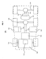
FIG. 1 illustrates a block representation of a hybrid vehicle configured with an embodiment of the present invention. - In accordance with the present invention, a medium or heavy duty hybrid
electric vehicle 100 is shown inFIG. 1 . The hybridelectric vehicle 100 includes aninternal combustion engine 102. Theinternal combustion engine 102 is of a conventional type that uses gasoline, diesel, bio-diesel, compressed natural gas (CNG), or other conventional fuel for initiating and sustaining combustion in one or more combustion chambers. As the workings of theinternal combustion engine 102 are well known in the art, the present disclosure will forego providing a detailed description of the operation of theinternal combustion engine 102 herein for brevity. - The
engine 102 is mechanically coupled to atransmission assembly 104 anddrive shaft 106. Thetransmission 104 provides driver-controlled or vehicle computer-controlled gear ratio selection from among a plurality of gear ratios depending on velocity, torque and acceleration requirements. In turn, the drive shaft is mechanically coupled to amiddle drive axle 108. - In the embodiment shown in
FIG. 1 , thedrive axle 108 is the center axle of a three axle arrangement. However, the present invention is not limited to three axle vehicles alone, but rather may be equally applied to vehicles with more than three axles as well. Thus, in the arrangement shown inFIG. 1 , motive energy generated by theengine 102 is directed, through thetransmission assembly 104 anddrive shaft 106, to themiddle drive axle 108. Theengine 102, in a three axle vehicle, can be configured to drive thefront-most axle 103 by way of internal gearsets, as well as themiddle drive axle 108. - The
engine 102 in the present invention is configured to provide the bulk of the driving energy used by thevehicle 100. Specifically, theengine 102, in combination with thetransmission assembly 104, is configured to provide enough power to efficiently operate the vehicle at a constant cruising velocity of, for example, between 50 and 80 miles per hour. Theengine 102 may be equipped with aturbo assembly 110 in order to provide additional acceleration power without requiring a larger displacement engine and subsequent reduction in cruising efficiency. Alternatively, theengine 102 may employ variable displacement technologies to control the number of combustion chambers utilized under a given driving condition to optimize fuel usage. - In addition to the conventional
internal combustion engine 102 drive system described above, thevehicle 100 includes a second drive system utilizing anelectric motor 120, andclutch assembly 122 mechanically coupled to arear-most drive axle 124, by way of asecond drive shaft 123. In an embodiment of the present invention, theclutch assembly 122 is a dry clutch housed with theelectric motor 120 as a single integrated unit. Alternatively, theclutch assembly 122 may be housed separately from theelectric motor 120. Also, the clutch assembly of the present invention is not limited to only a dry clutch; other clutch designs may be used as appropriate. - As shown in
FIG. 1 , theelectric motor 120 is positioned forward of therear-most drive axle 124. However, in alternative embodiments, theelectric motor 120 may be placed behind or above therear-most drive axle 124. - The
electric motor 120 receives electrical energy fromenergy storage unit 126, such as Lithium-Ion batteries, hydrogen fuel cells, or other energy storage technologies capable of providing the necessary electrical power to theelectric motor 120. Collectively, these various energy storage technologies are referred herein generically as batteries. Amotor controller 128 is provided as well, to control the operation of theelectric motor 120, as described below. - The
energy storage unit 126 is configured to provide a high voltage output adequate to drive theelectric motor 120. The high voltage output from the battery can be in the hundreds of volts, for example 325 Volts DC. Therefore, a DC-to-DC converter 130 may be provided in electrical communication between the high voltage batteries and vehicle accessories for stepping down the high voltage output of the batteries to more appropriate voltages used by the accessories, such as 12 or 24 Volts DC. The use of a DC-to-DC converter 130 allows theenergy storage unit 126 to provide low voltage power to the low voltage batteries/conventional batteries, and provide power to accessories comprising a hotel load when the engine is not operating. - In the arrangement described above and shown in
FIG. 1 , theengine 102 provides the primary motive energy for thevehicle 100. Theelectric motor 120 provides supplemental motive power, which allows theengine 102 to have a smaller displacement than would otherwise be required to drive the vehicle. As long as theelectric motor 120 is supplied with adequate electric energy form theenergy storage unit 126, theelectric motor 120 supplements the engine power output by separately driving therear-most drive axle 124. Theclutch assembly 122 mechanically engages theelectric motor 120 to therear-most drive axle 124 when the supplemental motive power is desired. - When not actively powering the
rear-most drive axle 124, themotor controller 128 controls theclutch assembly 122 to disengage, thus mechanically isolating, theelectric motor 120 from therear-most drive axle 124. By isolating theelectric motor 120 from therear-most drive axle 124, parasitic power loss due to theelectric motor 120 acting as a load is eliminated. Consequently, the drive system disclosed herein is capable of visualizing greater fuel efficiency than conventional drive systems. - Additionally, during periods of deceleration, either by friction braking or dynamic braking (i.e., engine braking), the
motor controller 128 controls theclutch assembly 122 to engage theelectric motor 120 with therear-most drive axle 124. In the braking situation, this configuration allows the electric motor to operate as an electric generator in order to recoup braking energy for recharging theenergy storage unit 126. Moreover, theenergy storage unit 126 can be charged via a plug-in connection to an electrical power grid. - The described embodiments of the present invention are intended to be illustrative rather than restrictive, and are not intended to represent every embodiment of the present invention. Various modifications and variations can be made without departing from the scope of the invention as set forth in the following claims.
Claims (9)
- A hybrid drive system for a vehicle having a front drive axle (103), a middle drive axle (108) and a rear drive axle (124), the hybrid drive system comprising:an internal combustion engine (102);a first drive shaft (106) in mechanical communication with the engine (102) and the middle drive axle (108);an electric motor (120) including a clutch assembly (122);a second driveshaft (123) in mechanical communication with the electric motor (120) and the rear drive axle (124), the rear drive axle (124) and the middle drive axle (108) being mechanically isolated from one another;an energy storage unit (126) for storing and providing energizing power to the electric motor (120), the energy storage unit being in electrical communication with the electric motor; and characterized bya drive controller (128) for controlling the electric motor (120) and the clutch assembly (122), the drive controller controlling engagement of the clutch assembly only:when supplemental motive power is demanded to supplement primary motive power generated by the internal combustion engine (102) to transfer power from the electric motor (120) to the rear drive axle (124), andwhen the vehicle is decelerating to transfer motive power from the rear drive axle (124) to the electric motor (120) to recharge the energy storage unit, and the drive controller is configured to control disengagement of the clutch assembly (122) at other times including when the internal combustion engine satisfies a demanded motive power during cruising or acceleration of the vehicle in order to isolate the electric motor (120) from the rear drive axle (124).
- The hybrid drive system as in claim 1, wherein the energy storage unit (126) receives charging energy from the electric motor (120) operating as an electric generator during periods of recuperative braking.
- The hybrid drive system as in one of the claims 1 to 2, wherein the electric motor (120) is disposed between the rear-most drive axle (124) and the middle drive axle (108).
- The hybrid drive system as in one of the claims 1 to 3, wherein the drive controller controls engagement of the clutch assembly (122) during vehicle braking for generating recuperative energy by the electric motor operating as a generator.
- The hybrid drive system as in one of the claims 1 to 4, wherein the drive controller controls disengagement of the clutch assembly (122) to decouple the electric motor (120) from the rear-most drive axle (124) when recuperative energy is not desired.
- The hybrid drive system as in one of the claims 1 to 5, wherein the electric motor (120) and the clutch assembly (122) are integrated.
- The hybrid drive system as in one of the claims 1 to 6, wherein the engine (102) is coupled to the front drive axle (103).
- The hybrid drive system according to one of the previous claims comprising:a primary drive sub-system having the front drive axle (103), the middle drive axle (108), the internal combustion engine (102) and the first drive shaft (106),wherein the front drive axle (103) is located at a forward position of the vehicle;wherein the middle drive axle (108) is positioned at a distance behind the front drive axle;wherein the internal combustion engine (102) is dimensioned for providing the primary source of motive power, the internal combustion engine having an internal coupling to the front drive axle (103); anda supplemental drive sub-system electrically and mechanically isolated from the primary drive sub-system, the supplemental drive sub-system having the electric motor (120), the energy storage unit (126), the clutch assembly (122), the rear drive axle (124) and the second driveshaft (123),wherein the electric motor (120) is dimensioned for providing supplemental motive power;wherein the energy storage unit (126) is for storing electric energy supplied to the electric motor;wherein the clutch assembly (122) is for selectively engaging and disengaging the electric motor;wherein the rear drive axle (124) is positioned at a distance behind the middle drive axle; andwherein the second driveshaft (123) is in mechanical communication between the clutch assembly and the rear-most drive axle.
- A hybrid-electric vehicle, comprising:a vehicle body, having a plurality of drive axles;the hybrid drive system according to one of the previous claims.
Applications Claiming Priority (2)
| Application Number | Priority Date | Filing Date | Title |
|---|---|---|---|
| US12/714,809 US8875819B2 (en) | 2010-03-01 | 2010-03-01 | Hybrid drive system for hybrid electric vehicles |
| PCT/US2011/025692 WO2011109187A2 (en) | 2010-03-01 | 2011-02-22 | Hybrid drive system for hybrid electric vehicles |
Publications (3)
| Publication Number | Publication Date |
|---|---|
| EP2542440A2 EP2542440A2 (en) | 2013-01-09 |
| EP2542440A4 EP2542440A4 (en) | 2013-12-18 |
| EP2542440B1 true EP2542440B1 (en) | 2015-04-08 |
Family
ID=44504701
Family Applications (1)
| Application Number | Title | Priority Date | Filing Date |
|---|---|---|---|
| EP11751071.9A Not-in-force EP2542440B1 (en) | 2010-03-01 | 2011-02-22 | Hybrid drive system for hybrid electric vehicles |
Country Status (3)
| Country | Link |
|---|---|
| US (1) | US8875819B2 (en) |
| EP (1) | EP2542440B1 (en) |
| WO (1) | WO2011109187A2 (en) |
Families Citing this family (10)
| Publication number | Priority date | Publication date | Assignee | Title |
|---|---|---|---|---|
| ITTO20100310A1 (en) * | 2010-04-16 | 2011-10-17 | Movimatica Srl | ELECTRIC HYDRAULIC HYDRAULIC LIFT VEHICLE |
| US20140116793A1 (en) * | 2011-06-09 | 2014-05-01 | Prevost, Une Division De Groupe Volvo Canada Inc. | Hybrid vehicle |
| DE102013019907B4 (en) | 2013-11-28 | 2021-02-04 | Audi Ag | Active differential and motor vehicle |
| RU2569505C1 (en) * | 2014-04-22 | 2015-11-27 | Российская Федерация, От Имени Которой Выступает Министерство Промышленности И Торговли Российской Федерации | Six-wheel vehicle with combined drive |
| CN104097501A (en) * | 2014-07-18 | 2014-10-15 | 湖北航天技术研究院特种车辆技术中心 | Hybrid structure for multi-axle heavy off-road vehicle |
| US10150358B2 (en) * | 2015-12-17 | 2018-12-11 | Erik Orlando Soto | Generator and electrical motor for multi-axle vehicles |
| CN111971196B (en) | 2018-04-13 | 2024-03-26 | 德纳重型车辆系统集团有限责任公司 | Control strategy for single-mode and multi-mode electric auxiliary or support bridges |
| CN109263467A (en) * | 2018-10-25 | 2019-01-25 | 北京航天发射技术研究所 | Multi-axis special vehicle hybrid electric all-electric drive system |
| DE102019126119A1 (en) * | 2019-09-27 | 2021-04-01 | Mtm Motoren-Technik-Mayer Gmbh | VEHICLE WITH AT LEAST THREE DRIVEN WHEEL AXLES |
| US12005976B2 (en) * | 2020-11-12 | 2024-06-11 | Electrocamion Inc. | Hybrid tractor truck |
Family Cites Families (25)
| Publication number | Priority date | Publication date | Assignee | Title |
|---|---|---|---|---|
| FR2602468B1 (en) | 1986-08-08 | 1991-02-08 | Legueu Paul | AUTOMOTIVE VEHICLE WITH WHEELS, OF THE ALL-TERRAIN TYPE WITH INTEGRAL TRANSMISSION |
| FR2653718A1 (en) * | 1989-10-26 | 1991-05-03 | Sita | METHOD OF DIFFERENTIATED TRANSPORT AND VEHICLES FOR THEIR PRODUCTION. |
| JP3609491B2 (en) * | 1995-06-19 | 2005-01-12 | 本田技研工業株式会社 | Front and rear wheel drive vehicle |
| US6387007B1 (en) | 1997-01-24 | 2002-05-14 | Anthony W. Fini, Jr. | Electromechanical vehicle regeneration system |
| JP3425730B2 (en) | 1998-03-31 | 2003-07-14 | 本田技研工業株式会社 | Control device for hybrid vehicle |
| FR2799697B1 (en) | 1999-10-19 | 2004-01-30 | Giovanni Tonarelli | SEMI-TRAILER OR TRACTOR OR ROAD TRUCK, EQUIPPED WITH AN ELECTRIC BRIDGE AND A CONTACT PANTOGRAPH, FOR HYBRID, ELECTRIC OR THERMAL ROLLING |
| JP3546408B2 (en) * | 2000-11-13 | 2004-07-28 | 本田技研工業株式会社 | Control device for front and rear wheel drive vehicles |
| US6638195B2 (en) | 2002-02-27 | 2003-10-28 | New Venture Gear, Inc. | Hybrid vehicle system |
| US7520354B2 (en) * | 2002-05-02 | 2009-04-21 | Oshkosh Truck Corporation | Hybrid vehicle with combustion engine/electric motor drive |
| US6719379B2 (en) | 2002-06-20 | 2004-04-13 | Ford Motor Company | Method and an apparatus for braking a vehicle |
| US6888273B2 (en) | 2002-10-31 | 2005-05-03 | Eaton Corporation | Integrated motor and clutch assembly |
| CA2418686A1 (en) * | 2003-02-07 | 2004-08-07 | Gaetan Leclerc | Motorized semi-trailer |
| JP3661689B2 (en) | 2003-03-11 | 2005-06-15 | トヨタ自動車株式会社 | Motor drive device, hybrid vehicle drive device including the same, and computer-readable recording medium storing a program for causing a computer to control the motor drive device |
| JP2004328991A (en) | 2003-04-09 | 2004-11-18 | Nissan Motor Co Ltd | Left and right wheel drive system for vehicles |
| US7296644B2 (en) * | 2003-07-09 | 2007-11-20 | Tochigi Fuji Sangyo Kabushiki Kaisha | Reduction-drive device |
| US7140461B2 (en) | 2003-11-26 | 2006-11-28 | Oshkosh Truck Corporation | Power splitting vehicle drive system |
| JP3701662B2 (en) | 2004-02-18 | 2005-10-05 | 本田技研工業株式会社 | Automatic transmission control device for hybrid vehicle |
| US7572201B2 (en) | 2005-10-20 | 2009-08-11 | Ford Global Technologies, Llc | Electric hybrid powertrain system |
| US20070158119A1 (en) * | 2006-01-06 | 2007-07-12 | Pascoe David M | Independent axle motors for a road coupled hybrid vehicle |
| JP2007237905A (en) | 2006-03-08 | 2007-09-20 | Denso Corp | Program rewriting system and electronic control device for hybrid vehicle |
| US8043194B2 (en) | 2007-10-05 | 2011-10-25 | Ford Global Technologies, Llc | Vehicle creep control in a hybrid electric vehicle |
| US7691027B2 (en) | 2007-11-29 | 2010-04-06 | Ford Global Technologies, Llc | Idle speed control of a hybrid electric vehicle |
| US20090166106A1 (en) | 2007-12-27 | 2009-07-02 | Scott Daniel Batdorf | Vehicles Having Tandem Axle Assembly |
| EP2259945B1 (en) | 2008-02-29 | 2014-11-26 | Volvo Construction Equipment AB | A hybrid electrical working machine |
| DE102008030581A1 (en) | 2008-06-27 | 2009-12-31 | Daimler Ag | Drive train for a motor vehicle and method for operating a drive train of a motor vehicle |
-
2010
- 2010-03-01 US US12/714,809 patent/US8875819B2/en active Active
-
2011
- 2011-02-22 WO PCT/US2011/025692 patent/WO2011109187A2/en not_active Ceased
- 2011-02-22 EP EP11751071.9A patent/EP2542440B1/en not_active Not-in-force
Also Published As
| Publication number | Publication date |
|---|---|
| WO2011109187A3 (en) | 2012-01-12 |
| US20110209933A1 (en) | 2011-09-01 |
| US8875819B2 (en) | 2014-11-04 |
| EP2542440A4 (en) | 2013-12-18 |
| WO2011109187A2 (en) | 2011-09-09 |
| EP2542440A2 (en) | 2013-01-09 |
Similar Documents
| Publication | Publication Date | Title |
|---|---|---|
| US8875819B2 (en) | Hybrid drive system for hybrid electric vehicles | |
| EP2117868B1 (en) | Hybrid power output system | |
| Govardhan | Fundamentals and classification of hybrid electric vehicles | |
| CN101186209B (en) | Mixed power system using electrical system to implement series-parallel power distribution | |
| CN103085648B (en) | For improving the system of the hybrid electric vehicle of electric model performance | |
| US7681676B2 (en) | Electric hybrid vehicle conversion | |
| CN102848913B (en) | A kind of range extended electric vehicle power system adopting planetary gearbox | |
| US20110000721A1 (en) | Hybrid parallel load assist systems and methods | |
| US20110017532A1 (en) | A hybrid powertrain | |
| CA2836671C (en) | Hybrid vehicle | |
| US8657046B2 (en) | Engine system | |
| US9254738B2 (en) | Recuperative transmission down shifting multiple gears and engine decoupling | |
| CN102874094B (en) | A kind of range extended electric vehicle power system adopting planetary wheel two-speed transmission | |
| US20070202976A1 (en) | Power regeneration system with electromagnetic variable speed control | |
| US8517129B2 (en) | Motorized dual engine power system | |
| US20140054100A1 (en) | All wheel drive system for hybrid vehicle | |
| US8152671B2 (en) | Single clutch, two planetary hybrid architecture | |
| WO2007047849A2 (en) | Regenerative charging system using declelertion and/or wind | |
| CN101152837B (en) | Hybrid drive | |
| US20130133180A1 (en) | Electric vehicle motion generator | |
| Namirian | Comprehensive overview of hybrid vehicle drivetrains | |
| EP2463169A1 (en) | A hybride vehicle | |
| US12515514B1 (en) | Hybrid electric drive system for a vehicle | |
| Luckose et al. | Introduction to hybrid electric vehicle systems | |
| Doğan et al. | Development of hybrid automotive transmissions |
Legal Events
| Date | Code | Title | Description |
|---|---|---|---|
| PUAI | Public reference made under article 153(3) epc to a published international application that has entered the european phase |
Free format text: ORIGINAL CODE: 0009012 |
|
| 17P | Request for examination filed |
Effective date: 20120831 |
|
| AK | Designated contracting states |
Kind code of ref document: A2 Designated state(s): AL AT BE BG CH CY CZ DE DK EE ES FI FR GB GR HR HU IE IS IT LI LT LU LV MC MK MT NL NO PL PT RO RS SE SI SK SM TR |
|
| DAX | Request for extension of the european patent (deleted) | ||
| A4 | Supplementary search report drawn up and despatched |
Effective date: 20131119 |
|
| RIC1 | Information provided on ipc code assigned before grant |
Ipc: B60K 6/42 20071001ALI20131113BHEP Ipc: B60K 17/24 20060101ALI20131113BHEP Ipc: B60K 17/22 20060101AFI20131113BHEP |
|
| REG | Reference to a national code |
Ref country code: DE Ref legal event code: R079 Ref document number: 602011015511 Country of ref document: DE Free format text: PREVIOUS MAIN CLASS: B60K0017220000 Ipc: B60K0006480000 |
|
| GRAJ | Information related to disapproval of communication of intention to grant by the applicant or resumption of examination proceedings by the epo deleted |
Free format text: ORIGINAL CODE: EPIDOSDIGR1 |
|
| GRAP | Despatch of communication of intention to grant a patent |
Free format text: ORIGINAL CODE: EPIDOSNIGR1 |
|
| RIC1 | Information provided on ipc code assigned before grant |
Ipc: B60K 6/48 20071001AFI20140826BHEP Ipc: B60W 30/18 20120101ALI20140826BHEP Ipc: B60W 10/02 20060101ALI20140826BHEP Ipc: B60W 10/08 20060101ALI20140826BHEP Ipc: B60K 6/52 20071001ALI20140826BHEP |
|
| INTG | Intention to grant announced |
Effective date: 20140929 |
|
| RAP1 | Party data changed (applicant data changed or rights of an application transferred) |
Owner name: BAE SYSTEMS CONTROLS INC. |
|
| GRAP | Despatch of communication of intention to grant a patent |
Free format text: ORIGINAL CODE: EPIDOSNIGR1 |
|
| GRAS | Grant fee paid |
Free format text: ORIGINAL CODE: EPIDOSNIGR3 |
|
| GRAA | (expected) grant |
Free format text: ORIGINAL CODE: 0009210 |
|
| INTG | Intention to grant announced |
Effective date: 20150216 |
|
| AK | Designated contracting states |
Kind code of ref document: B1 Designated state(s): AL AT BE BG CH CY CZ DE DK EE ES FI FR GB GR HR HU IE IS IT LI LT LU LV MC MK MT NL NO PL PT RO RS SE SI SK SM TR |
|
| REG | Reference to a national code |
Ref country code: GB Ref legal event code: FG4D |
|
| REG | Reference to a national code |
Ref country code: CH Ref legal event code: EP |
|
| REG | Reference to a national code |
Ref country code: IE Ref legal event code: FG4D |
|
| REG | Reference to a national code |
Ref country code: AT Ref legal event code: REF Ref document number: 720270 Country of ref document: AT Kind code of ref document: T Effective date: 20150515 |
|
| REG | Reference to a national code |
Ref country code: DE Ref legal event code: R096 Ref document number: 602011015511 Country of ref document: DE Effective date: 20150521 |
|
| REG | Reference to a national code |
Ref country code: AT Ref legal event code: MK05 Ref document number: 720270 Country of ref document: AT Kind code of ref document: T Effective date: 20150408 |
|
| REG | Reference to a national code |
Ref country code: NL Ref legal event code: VDEP Effective date: 20150408 |
|
| REG | Reference to a national code |
Ref country code: LT Ref legal event code: MG4D |
|
| PG25 | Lapsed in a contracting state [announced via postgrant information from national office to epo] |
Ref country code: NL Free format text: LAPSE BECAUSE OF FAILURE TO SUBMIT A TRANSLATION OF THE DESCRIPTION OR TO PAY THE FEE WITHIN THE PRESCRIBED TIME-LIMIT Effective date: 20150408 |
|
| PG25 | Lapsed in a contracting state [announced via postgrant information from national office to epo] |
Ref country code: PT Free format text: LAPSE BECAUSE OF FAILURE TO SUBMIT A TRANSLATION OF THE DESCRIPTION OR TO PAY THE FEE WITHIN THE PRESCRIBED TIME-LIMIT Effective date: 20150810 Ref country code: FI Free format text: LAPSE BECAUSE OF FAILURE TO SUBMIT A TRANSLATION OF THE DESCRIPTION OR TO PAY THE FEE WITHIN THE PRESCRIBED TIME-LIMIT Effective date: 20150408 Ref country code: HR Free format text: LAPSE BECAUSE OF FAILURE TO SUBMIT A TRANSLATION OF THE DESCRIPTION OR TO PAY THE FEE WITHIN THE PRESCRIBED TIME-LIMIT Effective date: 20150408 Ref country code: LT Free format text: LAPSE BECAUSE OF FAILURE TO SUBMIT A TRANSLATION OF THE DESCRIPTION OR TO PAY THE FEE WITHIN THE PRESCRIBED TIME-LIMIT Effective date: 20150408 Ref country code: NO Free format text: LAPSE BECAUSE OF FAILURE TO SUBMIT A TRANSLATION OF THE DESCRIPTION OR TO PAY THE FEE WITHIN THE PRESCRIBED TIME-LIMIT Effective date: 20150708 Ref country code: ES Free format text: LAPSE BECAUSE OF FAILURE TO SUBMIT A TRANSLATION OF THE DESCRIPTION OR TO PAY THE FEE WITHIN THE PRESCRIBED TIME-LIMIT Effective date: 20150408 |
|
| PG25 | Lapsed in a contracting state [announced via postgrant information from national office to epo] |
Ref country code: LV Free format text: LAPSE BECAUSE OF FAILURE TO SUBMIT A TRANSLATION OF THE DESCRIPTION OR TO PAY THE FEE WITHIN THE PRESCRIBED TIME-LIMIT Effective date: 20150408 Ref country code: AT Free format text: LAPSE BECAUSE OF FAILURE TO SUBMIT A TRANSLATION OF THE DESCRIPTION OR TO PAY THE FEE WITHIN THE PRESCRIBED TIME-LIMIT Effective date: 20150408 Ref country code: GR Free format text: LAPSE BECAUSE OF FAILURE TO SUBMIT A TRANSLATION OF THE DESCRIPTION OR TO PAY THE FEE WITHIN THE PRESCRIBED TIME-LIMIT Effective date: 20150709 Ref country code: IS Free format text: LAPSE BECAUSE OF FAILURE TO SUBMIT A TRANSLATION OF THE DESCRIPTION OR TO PAY THE FEE WITHIN THE PRESCRIBED TIME-LIMIT Effective date: 20150808 Ref country code: RS Free format text: LAPSE BECAUSE OF FAILURE TO SUBMIT A TRANSLATION OF THE DESCRIPTION OR TO PAY THE FEE WITHIN THE PRESCRIBED TIME-LIMIT Effective date: 20150408 |
|
| REG | Reference to a national code |
Ref country code: DE Ref legal event code: R097 Ref document number: 602011015511 Country of ref document: DE |
|
| PG25 | Lapsed in a contracting state [announced via postgrant information from national office to epo] |
Ref country code: DK Free format text: LAPSE BECAUSE OF FAILURE TO SUBMIT A TRANSLATION OF THE DESCRIPTION OR TO PAY THE FEE WITHIN THE PRESCRIBED TIME-LIMIT Effective date: 20150408 Ref country code: EE Free format text: LAPSE BECAUSE OF FAILURE TO SUBMIT A TRANSLATION OF THE DESCRIPTION OR TO PAY THE FEE WITHIN THE PRESCRIBED TIME-LIMIT Effective date: 20150408 |
|
| PLBE | No opposition filed within time limit |
Free format text: ORIGINAL CODE: 0009261 |
|
| STAA | Information on the status of an ep patent application or granted ep patent |
Free format text: STATUS: NO OPPOSITION FILED WITHIN TIME LIMIT |
|
| REG | Reference to a national code |
Ref country code: FR Ref legal event code: PLFP Year of fee payment: 6 |
|
| PG25 | Lapsed in a contracting state [announced via postgrant information from national office to epo] |
Ref country code: CZ Free format text: LAPSE BECAUSE OF FAILURE TO SUBMIT A TRANSLATION OF THE DESCRIPTION OR TO PAY THE FEE WITHIN THE PRESCRIBED TIME-LIMIT Effective date: 20150408 Ref country code: PL Free format text: LAPSE BECAUSE OF FAILURE TO SUBMIT A TRANSLATION OF THE DESCRIPTION OR TO PAY THE FEE WITHIN THE PRESCRIBED TIME-LIMIT Effective date: 20150408 Ref country code: RO Free format text: LAPSE BECAUSE OF NON-PAYMENT OF DUE FEES Effective date: 20150408 Ref country code: SK Free format text: LAPSE BECAUSE OF FAILURE TO SUBMIT A TRANSLATION OF THE DESCRIPTION OR TO PAY THE FEE WITHIN THE PRESCRIBED TIME-LIMIT Effective date: 20150408 |
|
| 26N | No opposition filed |
Effective date: 20160111 |
|
| PG25 | Lapsed in a contracting state [announced via postgrant information from national office to epo] |
Ref country code: IT Free format text: LAPSE BECAUSE OF FAILURE TO SUBMIT A TRANSLATION OF THE DESCRIPTION OR TO PAY THE FEE WITHIN THE PRESCRIBED TIME-LIMIT Effective date: 20150408 |
|
| PG25 | Lapsed in a contracting state [announced via postgrant information from national office to epo] |
Ref country code: BE Free format text: LAPSE BECAUSE OF NON-PAYMENT OF DUE FEES Effective date: 20160229 Ref country code: SI Free format text: LAPSE BECAUSE OF FAILURE TO SUBMIT A TRANSLATION OF THE DESCRIPTION OR TO PAY THE FEE WITHIN THE PRESCRIBED TIME-LIMIT Effective date: 20150408 |
|
| PG25 | Lapsed in a contracting state [announced via postgrant information from national office to epo] |
Ref country code: BE Free format text: LAPSE BECAUSE OF FAILURE TO SUBMIT A TRANSLATION OF THE DESCRIPTION OR TO PAY THE FEE WITHIN THE PRESCRIBED TIME-LIMIT Effective date: 20150408 |
|
| REG | Reference to a national code |
Ref country code: DE Ref legal event code: R119 Ref document number: 602011015511 Country of ref document: DE |
|
| PG25 | Lapsed in a contracting state [announced via postgrant information from national office to epo] |
Ref country code: LU Free format text: LAPSE BECAUSE OF FAILURE TO SUBMIT A TRANSLATION OF THE DESCRIPTION OR TO PAY THE FEE WITHIN THE PRESCRIBED TIME-LIMIT Effective date: 20160222 Ref country code: MC Free format text: LAPSE BECAUSE OF FAILURE TO SUBMIT A TRANSLATION OF THE DESCRIPTION OR TO PAY THE FEE WITHIN THE PRESCRIBED TIME-LIMIT Effective date: 20150408 |
|
| REG | Reference to a national code |
Ref country code: CH Ref legal event code: PL |
|
| PG25 | Lapsed in a contracting state [announced via postgrant information from national office to epo] |
Ref country code: LI Free format text: LAPSE BECAUSE OF NON-PAYMENT OF DUE FEES Effective date: 20160229 Ref country code: CH Free format text: LAPSE BECAUSE OF NON-PAYMENT OF DUE FEES Effective date: 20160229 |
|
| REG | Reference to a national code |
Ref country code: IE Ref legal event code: MM4A |
|
| PG25 | Lapsed in a contracting state [announced via postgrant information from national office to epo] |
Ref country code: IE Free format text: LAPSE BECAUSE OF NON-PAYMENT OF DUE FEES Effective date: 20160222 Ref country code: DE Free format text: LAPSE BECAUSE OF NON-PAYMENT OF DUE FEES Effective date: 20160901 |
|
| REG | Reference to a national code |
Ref country code: FR Ref legal event code: PLFP Year of fee payment: 7 |
|
| PG25 | Lapsed in a contracting state [announced via postgrant information from national office to epo] |
Ref country code: SE Free format text: LAPSE BECAUSE OF FAILURE TO SUBMIT A TRANSLATION OF THE DESCRIPTION OR TO PAY THE FEE WITHIN THE PRESCRIBED TIME-LIMIT Effective date: 20150408 |
|
| PG25 | Lapsed in a contracting state [announced via postgrant information from national office to epo] |
Ref country code: MT Free format text: LAPSE BECAUSE OF FAILURE TO SUBMIT A TRANSLATION OF THE DESCRIPTION OR TO PAY THE FEE WITHIN THE PRESCRIBED TIME-LIMIT Effective date: 20150408 |
|
| REG | Reference to a national code |
Ref country code: FR Ref legal event code: PLFP Year of fee payment: 8 |
|
| PG25 | Lapsed in a contracting state [announced via postgrant information from national office to epo] |
Ref country code: CY Free format text: LAPSE BECAUSE OF FAILURE TO SUBMIT A TRANSLATION OF THE DESCRIPTION OR TO PAY THE FEE WITHIN THE PRESCRIBED TIME-LIMIT Effective date: 20150408 Ref country code: HU Free format text: LAPSE BECAUSE OF FAILURE TO SUBMIT A TRANSLATION OF THE DESCRIPTION OR TO PAY THE FEE WITHIN THE PRESCRIBED TIME-LIMIT; INVALID AB INITIO Effective date: 20110222 Ref country code: SM Free format text: LAPSE BECAUSE OF FAILURE TO SUBMIT A TRANSLATION OF THE DESCRIPTION OR TO PAY THE FEE WITHIN THE PRESCRIBED TIME-LIMIT Effective date: 20150408 |
|
| PG25 | Lapsed in a contracting state [announced via postgrant information from national office to epo] |
Ref country code: TR Free format text: LAPSE BECAUSE OF FAILURE TO SUBMIT A TRANSLATION OF THE DESCRIPTION OR TO PAY THE FEE WITHIN THE PRESCRIBED TIME-LIMIT Effective date: 20150408 Ref country code: MK Free format text: LAPSE BECAUSE OF FAILURE TO SUBMIT A TRANSLATION OF THE DESCRIPTION OR TO PAY THE FEE WITHIN THE PRESCRIBED TIME-LIMIT Effective date: 20150408 Ref country code: MT Free format text: LAPSE BECAUSE OF FAILURE TO SUBMIT A TRANSLATION OF THE DESCRIPTION OR TO PAY THE FEE WITHIN THE PRESCRIBED TIME-LIMIT Effective date: 20160229 |
|
| PG25 | Lapsed in a contracting state [announced via postgrant information from national office to epo] |
Ref country code: BG Free format text: LAPSE BECAUSE OF FAILURE TO SUBMIT A TRANSLATION OF THE DESCRIPTION OR TO PAY THE FEE WITHIN THE PRESCRIBED TIME-LIMIT Effective date: 20150408 |
|
| PG25 | Lapsed in a contracting state [announced via postgrant information from national office to epo] |
Ref country code: AL Free format text: LAPSE BECAUSE OF FAILURE TO SUBMIT A TRANSLATION OF THE DESCRIPTION OR TO PAY THE FEE WITHIN THE PRESCRIBED TIME-LIMIT Effective date: 20150408 |
|
| RIC2 | Information provided on ipc code assigned after grant |
Ipc: B60W 10/08 20060101ALI20140826BHEP Ipc: B60K 6/52 20071001ALI20140826BHEP Ipc: B60W 10/02 20060101ALI20140826BHEP Ipc: B60W 30/18 20120101ALI20140826BHEP Ipc: B60K 6/48 20071001AFI20140826BHEP |
|
| PGFP | Annual fee paid to national office [announced via postgrant information from national office to epo] |
Ref country code: GB Payment date: 20240227 Year of fee payment: 14 |
|
| PGFP | Annual fee paid to national office [announced via postgrant information from national office to epo] |
Ref country code: FR Payment date: 20240226 Year of fee payment: 14 |
|
| GBPC | Gb: european patent ceased through non-payment of renewal fee |
Effective date: 20250222 |
|
| PG25 | Lapsed in a contracting state [announced via postgrant information from national office to epo] |
Ref country code: GB Free format text: LAPSE BECAUSE OF NON-PAYMENT OF DUE FEES Effective date: 20250222 |
|
| PG25 | Lapsed in a contracting state [announced via postgrant information from national office to epo] |
Ref country code: FR Free format text: LAPSE BECAUSE OF NON-PAYMENT OF DUE FEES Effective date: 20250228 |