EP2541839A1 - Method of determining immediate topology of a network connection - Google Patents
Method of determining immediate topology of a network connection Download PDFInfo
- Publication number
- EP2541839A1 EP2541839A1 EP12173934A EP12173934A EP2541839A1 EP 2541839 A1 EP2541839 A1 EP 2541839A1 EP 12173934 A EP12173934 A EP 12173934A EP 12173934 A EP12173934 A EP 12173934A EP 2541839 A1 EP2541839 A1 EP 2541839A1
- Authority
- EP
- European Patent Office
- Prior art keywords
- switch
- determining
- packets
- managed switch
- tool
- Prior art date
- Legal status (The legal status is an assumption and is not a legal conclusion. Google has not performed a legal analysis and makes no representation as to the accuracy of the status listed.)
- Granted
Links
Images
Classifications
-
- H—ELECTRICITY
- H04—ELECTRIC COMMUNICATION TECHNIQUE
- H04L—TRANSMISSION OF DIGITAL INFORMATION, e.g. TELEGRAPHIC COMMUNICATION
- H04L43/00—Arrangements for monitoring or testing data switching networks
- H04L43/50—Testing arrangements
-
- H—ELECTRICITY
- H04—ELECTRIC COMMUNICATION TECHNIQUE
- H04L—TRANSMISSION OF DIGITAL INFORMATION, e.g. TELEGRAPHIC COMMUNICATION
- H04L12/00—Data switching networks
- H04L12/02—Details
- H04L12/12—Arrangements for remote connection or disconnection of substations or of equipment thereof
-
- H—ELECTRICITY
- H04—ELECTRIC COMMUNICATION TECHNIQUE
- H04L—TRANSMISSION OF DIGITAL INFORMATION, e.g. TELEGRAPHIC COMMUNICATION
- H04L41/00—Arrangements for maintenance, administration or management of data switching networks, e.g. of packet switching networks
- H04L41/12—Discovery or management of network topologies
-
- H—ELECTRICITY
- H04—ELECTRIC COMMUNICATION TECHNIQUE
- H04L—TRANSMISSION OF DIGITAL INFORMATION, e.g. TELEGRAPHIC COMMUNICATION
- H04L43/00—Arrangements for monitoring or testing data switching networks
- H04L43/08—Monitoring or testing based on specific metrics, e.g. QoS, energy consumption or environmental parameters
- H04L43/0805—Monitoring or testing based on specific metrics, e.g. QoS, energy consumption or environmental parameters by checking availability
- H04L43/0811—Monitoring or testing based on specific metrics, e.g. QoS, energy consumption or environmental parameters by checking availability by checking connectivity
Definitions
- This invention relates to test and measurement in data communications and more particularly to network topology determination.
- Unable to detect rogue switches The tools do not detect the presence of unwanted or rogue switch devices.
- the availability and proliferation of low cost, unmanaged switches e.g., $35 for 5 Port 10/100/1000 switch) makes them deployable by non-IT staff introducing unwanted port expansion, addition of network devices, and lower network reliability.
- SNMP Simple Network Management Protocol
- a network test tool determines whether it is linked directly to an indicated managed device or an intermediate unmanaged device. Analysis of initial packets, with timeouts, provide a determination of whether the tool is actually connected to an advertised nearest switch.
- the invention provides a hand held test instrument for determining immediate network topology, comprising an interface for connection with a network under test; and a tester for determining whether the instrument is connected to a nearest managed switch.
- the tester may be arranged for determining whether the instrument is connected to a nearest managed switch
- the hand held test instrument for determining immediate network topology may further determine whether an unmanaged switch is present before the nearest managed switch.
- the hand held test instrument for determining immediate network topology may further determine whether a hub is present before the nearest managed switch.
- the tester may be appropriately arranged to make this determination.
- the hand held test instrument for determining immediate network topology may further determine whether no managed switch is present.
- the tester may be appropriately arranged to make this determination.
- a method of determining immediate network topology comprising determining whether discovery protocol or spanning tree packets are received within initial packets; and if said determining determines that discovery protocol or spanning tree packets were received within initial packets, reporting connection to a nearest managed switch.
- the method may further comprise if said determining determines that discovery protocol or spanning tree packets were not received within initial packets but were received after initial packets, concluding that connection is not directly to a nearest managed switch.
- the method may further comprise determining whether multiple unicast destination MAC addresses are received during a time period and if so, concluding that a hub exists before a nearest managed switch.
- the method may further comprise determining whether multiple unicast destination MAC addresses are received during a time period and if not, concluding that an unmanaged switch exists before a nearest managed switch.
- the method may further comprise, if said determining determines that no discovery protocol or spanning tree packets were received within a timeout period, reporting that no managed switch is present.
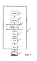
- FIG. 1 is a block diagram of a tool for determining network topology
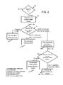
- FIG. 2 is a flow chart of operational steps for determining network topology.
- the system comprises a network test tool, adapted for determining network topology. This tool does not require SNMP.
- the tool 10 includes a interface 12 for connection to the network, which comprises an RJ-45 connector as employed in computer network environments.
- the RJ-45 connector allows connection of the tool to a network, represented by switch 14 in FIG. 1 .
- the connector interfaces the external signals to physical layer block 16, which operates to connect the media access controller (MAC) 18 to the physical medium of the network.
- MAC media access controller
- MAC 18 interfaces with a packet buffer 20, for storing packets received, for processing by processor 22.
- Processor 22 interfaces with a display 24 for providing test results and otherwise interfacing with a user.
- the display may include touch screen functionality for operational control of the tool, and/or user operable keys or other i/o devices may be provided for the user to employ in operating the tool.
- the processor 22 is operating the tool by initially waiting for link pulse on the connection, sent by a device when it is not sending or receiving data (block 26).
- initial frames are captured and analyzed, and a timer t is initialized to zero.
- Decision block 30 determines whether the initial frames are xDP (discovery protocol) or spanning tree packets (STP). If the initial frames are xDP (discovery protocol) or spanning tree packets, it is determined that the tool is connected to the nearest managed switch, and this information may be reported to the user, by an appropriate report of information related to this on display 24 (block 32).
- a timer t is started, initialized to zero, and at block 36, the process waits for multiple unicast destination MAC addresses or timeout. If more than 1 qualified destination MAC addresses are seen before timeout, it is determined at block 38 that a hub exists before the nearest managed switch, as the hub is transmitting all data that it sees. This determination may be reported to the user via display 24, for example.
- timeout occurs before more than 1 qualified destination MAC addresses are seen, the timeout value being 5 seconds in the illustrated embodiment, then it is determined that an unmanaged switch exists between the test tool and the nearest managed switch, block 40, and this determination may be reported to the user, again via display 24, for example
- timeout value is set to be 60 seconds.
- the network test tool 10 upon being connected to a network, determines whether it is directly connected to a managed switch, whether there is an intermediate unmanaged switch or hub, or whether no managed switch is present. The first few packets and timing are analyzed to provide a highly accurate indication of whether the tool is actually connected to the advertised nearest switch. This provides useful information for IT personnel in order to manage network operation.
Landscapes
- Engineering & Computer Science (AREA)
- Computer Networks & Wireless Communication (AREA)
- Signal Processing (AREA)
- Small-Scale Networks (AREA)
- Data Exchanges In Wide-Area Networks (AREA)
Abstract
Description
- Background of the Invention
- This invention relates to test and measurement in data communications and more particularly to network topology determination.
- In network test and measurement operation, it can be helpful to determining an accurate network connection topology for a user of a portable network test tool.
- Current test tools indicate network topology by reporting the first device that the tool is connected to, by monitoring for discovery protocol (Link Layer Discovery Protocol (LLDP), Cisco Discovery Protocol (CDP), or other discovery protocol), hereinafter xDP. This first device indication as implemented by these tools presents numerous problems:
- 1. Incorrect test indication: The tools incorrectly indicate the topology if there is an unmanaged switch or hub (hereinafter, switch) between the tool and the managed switch.
- 2. Unable to detect rogue switches: The tools do not detect the presence of unwanted or rogue switch devices. The availability and proliferation of low cost, unmanaged switches (e.g., $35 for 5
Port 10/100/1000 switch) makes them deployable by non-IT staff introducing unwanted port expansion, addition of network devices, and lower network reliability. - 3. Decreased user confidence: In the cases when the tools are linked to a known unmanaged switch (e.g. in front of the tool) the tools do not indicate its presence, instead indicating an immediate connection to the nearest managed switch. This obvious miss-indication erodes user confidence in other test results that the tools may provide.
- 4. SNMP reliance: In many situations SNMP (Simple Network Management Protocol) is not available due to either SNMP running on a separate management plane or that the SNMP community strings are not shared.
- Summary of the Invention
- In accordance with the invention, a network test tool determines whether it is linked directly to an indicated managed device or an intermediate unmanaged device. Analysis of initial packets, with timeouts, provide a determination of whether the tool is actually connected to an advertised nearest switch.
- Accordingly, it is an object of the present disclosure to provide an improved network test tool for determining network topology.
- It is a further object of the present disclosure to provide an improved network test device that will determine whether a managed switch is present, whether the tool is connected to a nearest switch, whether an unmanaged switch exists before the nearest switch, or whether a hub exists before the nearest switch.
- In one aspect, the invention provides a hand held test instrument for determining immediate network topology, comprising an interface for connection with a network under test; and a tester for determining whether the instrument is connected to a nearest managed switch. The tester may be arranged for determining whether the instrument is connected to a nearest managed switch
- The hand held test instrument for determining immediate network topology may further determine whether an unmanaged switch is present before the nearest managed switch.
- The hand held test instrument for determining immediate network topology may further determine whether a hub is present before the nearest managed switch. The tester may be appropriately arranged to make this determination.
- The hand held test instrument for determining immediate network topology may further determine whether no managed switch is present. The tester may be appropriately arranged to make this determination.
- A method of determining immediate network topology, comprising determining whether discovery protocol or spanning tree packets are received within initial packets; and if said determining determines that discovery protocol or spanning tree packets were received within initial packets, reporting connection to a nearest managed switch.
- The method may further comprise if said determining determines that discovery protocol or spanning tree packets were not received within initial packets but were received after initial packets, concluding that connection is not directly to a nearest managed switch.
- The method may further comprise determining whether multiple unicast destination MAC addresses are received during a time period and if so, concluding that a hub exists before a nearest managed switch.
- The method may further comprise determining whether multiple unicast destination MAC addresses are received during a time period and if not, concluding that an unmanaged switch exists before a nearest managed switch.
- The method may further comprise, if said determining determines that no discovery protocol or spanning tree packets were received within a timeout period, reporting that no managed switch is present.
- The subject matter of the present invention is particularly pointed out and distinctly claimed in the concluding portion of this specification. However, both the organization and method of operation, together with further advantages and objects thereof, may best be understood by reference to the following description taken in connection with accompanying drawings wherein like reference characters refer to like elements.
- Brief Description of the Drawings
-
FIG. 1 is a block diagram of a tool for determining network topology; and -
FIG. 2 is a flow chart of operational steps for determining network topology. - Detailed Description
- The system according to a preferred embodiment of the present disclosure comprises a network test tool, adapted for determining network topology. This tool does not require SNMP.
- Referring to
FIG. 1 , a block diagram of a tool for determining network topology, thetool 10 includes ainterface 12 for connection to the network, which comprises an RJ-45 connector as employed in computer network environments. The RJ-45 connector allows connection of the tool to a network, represented byswitch 14 inFIG. 1 . The connector interfaces the external signals tophysical layer block 16, which operates to connect the media access controller (MAC) 18 to the physical medium of the network. -
MAC 18 interfaces with apacket buffer 20, for storing packets received, for processing byprocessor 22.Processor 22 interfaces with adisplay 24 for providing test results and otherwise interfacing with a user. The display may include touch screen functionality for operational control of the tool, and/or user operable keys or other i/o devices may be provided for the user to employ in operating the tool. - Referring now to
FIG. 2 , flow chart of operational steps for determining network topology in accordance with the tool disclose herein, theprocessor 22 is operating the tool by initially waiting for link pulse on the connection, sent by a device when it is not sending or receiving data (block 26). On detection of link pulse, atblock 28, initial frames are captured and analyzed, and a timer t is initialized to zero.Decision block 30 determines whether the initial frames are xDP (discovery protocol) or spanning tree packets (STP). If the initial frames are xDP (discovery protocol) or spanning tree packets, it is determined that the tool is connected to the nearest managed switch, and this information may be reported to the user, by an appropriate report of information related to this on display 24 (block 32). - Returning to
decision block 30, if discovery protocol or spanning tree packets were received, but they were received after the initial packets, then atblock 34 it is noted that the tool is not connected directly to the nearest managed switch. A timer t is started, initialized to zero, and atblock 36, the process waits for multiple unicast destination MAC addresses or timeout. If more than 1 qualified destination MAC addresses are seen before timeout, it is determined atblock 38 that a hub exists before the nearest managed switch, as the hub is transmitting all data that it sees. This determination may be reported to the user viadisplay 24, for example. - If at
block 36, timeout occurs before more than 1 qualified destination MAC addresses are seen, the timeout value being 5 seconds in the illustrated embodiment, then it is determined that an unmanaged switch exists between the test tool and the nearest managed switch,block 40, and this determination may be reported to the user, again viadisplay 24, for example - Returning to
block 30, if a timeout occurs with no discovery protocol or spanning tree packets having been received, it is determined that no managed switch is present,block 42, which may be reported bydisplay 24, for example. In a particular embodiment, the timeout value is set to be 60 seconds. - Accordingly the
network test tool 10, upon being connected to a network, determines whether it is directly connected to a managed switch, whether there is an intermediate unmanaged switch or hub, or whether no managed switch is present. The first few packets and timing are analyzed to provide a highly accurate indication of whether the tool is actually connected to the advertised nearest switch. This provides useful information for IT personnel in order to manage network operation. - While a preferred embodiment of the present invention has been shown and described, it will be apparent to those skilled in the art that many changes and modifications may be made without departing from the invention in its broader aspects. The appended claims are therefore intended to cover all such changes and modifications as fall within the true spirit and scope of the invention.
Claims (9)
- A hand held test instrument for determining immediate network topology, comprising: an interface for connection with a network under test; and a tester for determining whether the instrument is connected to a nearest managed switch.
- The hand held test instrument for determining immediate network topology according to claim 1, wherein said tester further determines whether an unmanaged switch is present before the nearest managed switch.
- The hand held test instrument for determining immediate network topology according to either one of claims 1 and 2, wherein said tester further determines whether a hub is present before the nearest managed switch.
- The hand held test instrument for determining immediate network topology according to any one of claims 1 to 3, wherein said tester further determines whether no managed switch is present.
- A method of determining immediate network topology, comprising: determining whether discovery protocol or spanning tree packets are received within initial packets; and if said determining determines that discovery protocol or spanning tree packets were received within initial packets, reporting connection to a nearest managed switch.
- The method according to claim 5, further comprising: if said determining determines that discovery protocol or spanning tree packets were not received within initial packets but were received after initial packets, concluding that connection is not directly to a nearest managed switch.
- The method according to either one of claims 5 and 6, further comprising determining whether multiple unicast destination MAC addresses are received during a time period and if so, concluding that a hub exists before a nearest managed switch.
- The method according to any one of claims 5 to 7, further comprising determining whether multiple unicast destination MAC addresses are received during a time period and if not, concluding that an unmanaged switch exists before a nearest managed switch.
- The method according to any one of claims 5 to 8, further comprising, if said determining determines that no discovery protocol or spanning tree packets were received within a timeout period, reporting that no managed switch is present.
Applications Claiming Priority (1)
| Application Number | Priority Date | Filing Date | Title |
|---|---|---|---|
| US13/171,168 US8873433B2 (en) | 2011-06-28 | 2011-06-28 | Method of determining immediate topology of a network connection |
Publications (2)
| Publication Number | Publication Date |
|---|---|
| EP2541839A1 true EP2541839A1 (en) | 2013-01-02 |
| EP2541839B1 EP2541839B1 (en) | 2016-10-12 |
Family
ID=46758588
Family Applications (1)
| Application Number | Title | Priority Date | Filing Date |
|---|---|---|---|
| EP12173934.6A Active EP2541839B1 (en) | 2011-06-28 | 2012-06-27 | Method of determining immediate topology of a network connection |
Country Status (3)
| Country | Link |
|---|---|
| US (1) | US8873433B2 (en) |
| EP (1) | EP2541839B1 (en) |
| CN (1) | CN102857390B (en) |
Families Citing this family (3)
| Publication number | Priority date | Publication date | Assignee | Title |
|---|---|---|---|---|
| US10554662B2 (en) * | 2015-06-30 | 2020-02-04 | Mcafee, Llc | Security service for an unmanaged device |
| US10470111B1 (en) | 2018-04-25 | 2019-11-05 | Hewlett Packard Enterprise Development Lp | Protocol to detect if uplink is connected to 802.1D noncompliant device |
| CN112039696B (en) * | 2020-08-19 | 2023-04-07 | 浙江大华技术股份有限公司 | Method, device, equipment and medium for generating network topology structure |
Citations (3)
| Publication number | Priority date | Publication date | Assignee | Title |
|---|---|---|---|---|
| US20030065767A1 (en) * | 2001-10-03 | 2003-04-03 | Gautam Pardhy | Multiple ping management |
| US6747957B1 (en) * | 2000-04-28 | 2004-06-08 | Cisco Technology, Inc. | Network availability monitor |
| EP1528721A2 (en) * | 2003-10-27 | 2005-05-04 | Fluke Corporation | Network bridge uplink port identification |
Family Cites Families (1)
| Publication number | Priority date | Publication date | Assignee | Title |
|---|---|---|---|---|
| GB2462981B (en) * | 2007-06-19 | 2012-03-07 | Commscope Inc | Methods,systems, and computer program products for using managed port circuitry to map connections among structured cabling apparatus and network devices |
-
2011
- 2011-06-28 US US13/171,168 patent/US8873433B2/en active Active
-
2012
- 2012-06-27 EP EP12173934.6A patent/EP2541839B1/en active Active
- 2012-06-28 CN CN201210286923.9A patent/CN102857390B/en active Active
Patent Citations (3)
| Publication number | Priority date | Publication date | Assignee | Title |
|---|---|---|---|---|
| US6747957B1 (en) * | 2000-04-28 | 2004-06-08 | Cisco Technology, Inc. | Network availability monitor |
| US20030065767A1 (en) * | 2001-10-03 | 2003-04-03 | Gautam Pardhy | Multiple ping management |
| EP1528721A2 (en) * | 2003-10-27 | 2005-05-04 | Fluke Corporation | Network bridge uplink port identification |
Non-Patent Citations (1)
| Title |
|---|
| FLUKE NETWORKS: "Troubleshooting Guide for IndustrialEthernet and other Network Protocols", 31 December 2009 (2009-12-31), pages 1 - 14, XP002684784, Retrieved from the Internet <URL:http://www.newark.com/pdfs/techarticles/fluke/3456874_6513_ENG_A_W.PDF> [retrieved on 20121008] * |
Also Published As
| Publication number | Publication date |
|---|---|
| US20130003558A1 (en) | 2013-01-03 |
| EP2541839B1 (en) | 2016-10-12 |
| CN102857390B (en) | 2017-10-24 |
| CN102857390A (en) | 2013-01-02 |
| US8873433B2 (en) | 2014-10-28 |
Similar Documents
| Publication | Publication Date | Title |
|---|---|---|
| AU2019399138B2 (en) | Apparatus and process for detecting network security attacks on IoT devices | |
| US8014297B2 (en) | Network test apparatus, network test method and network test program | |
| US8369227B2 (en) | Management system and information processing system | |
| US7743274B2 (en) | Administering correlated error logs in a computer system | |
| CN114157554B (en) | Fault checking method and device, storage medium and computer equipment | |
| US20170264502A1 (en) | Network test instrument | |
| EP3682595B1 (en) | Obtaining local area network diagnostic test results | |
| CN114584485B (en) | Method, apparatus, device and computer readable storage medium for detecting edge network quality | |
| US20160119181A1 (en) | Network state monitoring system | |
| JP2008283621A (en) | Apparatus and method for monitoring network congestion state, and program | |
| CN102098188A (en) | Method and system for detecting IP (Internet Protocol) connection | |
| JP3868939B2 (en) | Device for detecting a failure in a communication network | |
| US8873433B2 (en) | Method of determining immediate topology of a network connection | |
| US20120163212A1 (en) | Apparatus and method for detecting abnormal traffic | |
| US7394773B2 (en) | Network bridge uplink port identification | |
| CN104618181A (en) | Method for detecting intranet operation system of power system based on NMAP (Network Mapper) | |
| US8064454B2 (en) | Protocol incompatibility detection | |
| US20160127231A1 (en) | Information processing system, method, and management device | |
| US7817555B2 (en) | Compacting of frames in a network diagnostic device | |
| JP2023032853A (en) | Flow information collection device and flow information generation method | |
| CN116980283A (en) | Fault determination method and device and computing equipment | |
| JP5427913B2 (en) | Management system and information processing system | |
| CN108540339A (en) | A kind of detecting system and its detection method of switch port configuration | |
| US20060229067A1 (en) | Wireless interface for test and measurement device | |
| JP7235714B2 (en) | Information processing device, determination method and determination program |
Legal Events
| Date | Code | Title | Description |
|---|---|---|---|
| PUAI | Public reference made under article 153(3) epc to a published international application that has entered the european phase |
Free format text: ORIGINAL CODE: 0009012 |
|
| AK | Designated contracting states |
Kind code of ref document: A1 Designated state(s): AL AT BE BG CH CY CZ DE DK EE ES FI FR GB GR HR HU IE IS IT LI LT LU LV MC MK MT NL NO PL PT RO RS SE SI SK SM TR |
|
| AX | Request for extension of the european patent |
Extension state: BA ME |
|
| 17P | Request for examination filed |
Effective date: 20130701 |
|
| RBV | Designated contracting states (corrected) |
Designated state(s): AL AT BE BG CH CY CZ DE DK EE ES FI FR GB GR HR HU IE IS IT LI LT LU LV MC MK MT NL NO PL PT RO RS SE SI SK SM TR |
|
| RAP1 | Party data changed (applicant data changed or rights of an application transferred) |
Owner name: FLUKE CORPORATION |
|
| RIN1 | Information on inventor provided before grant (corrected) |
Inventor name: FLUKE CORPORATION |
|
| REG | Reference to a national code |
Ref country code: DE Ref legal event code: R079 Ref document number: 602012023958 Country of ref document: DE Free format text: PREVIOUS MAIN CLASS: H04L0012260000 Ipc: H04L0012120000 |
|
| GRAP | Despatch of communication of intention to grant a patent |
Free format text: ORIGINAL CODE: EPIDOSNIGR1 |
|
| RAP1 | Party data changed (applicant data changed or rights of an application transferred) |
Owner name: AIRMAGNET, INC. |
|
| RIC1 | Information provided on ipc code assigned before grant |
Ipc: H04L 12/26 20060101ALI20160419BHEP Ipc: H04L 12/12 20060101AFI20160419BHEP Ipc: H04L 12/24 20060101ALI20160419BHEP |
|
| RIN1 | Information on inventor provided before grant (corrected) |
Inventor name: AIRMAGNET, INC. |
|
| INTG | Intention to grant announced |
Effective date: 20160506 |
|
| RIN1 | Information on inventor provided before grant (corrected) |
Inventor name: KAHKOSKA, JAMES |
|
| GRAS | Grant fee paid |
Free format text: ORIGINAL CODE: EPIDOSNIGR3 |
|
| GRAA | (expected) grant |
Free format text: ORIGINAL CODE: 0009210 |
|
| AK | Designated contracting states |
Kind code of ref document: B1 Designated state(s): AL AT BE BG CH CY CZ DE DK EE ES FI FR GB GR HR HU IE IS IT LI LT LU LV MC MK MT NL NO PL PT RO RS SE SI SK SM TR |
|
| REG | Reference to a national code |
Ref country code: GB Ref legal event code: FG4D |
|
| REG | Reference to a national code |
Ref country code: CH Ref legal event code: EP |
|
| REG | Reference to a national code |
Ref country code: AT Ref legal event code: REF Ref document number: 837344 Country of ref document: AT Kind code of ref document: T Effective date: 20161015 |
|
| REG | Reference to a national code |
Ref country code: IE Ref legal event code: FG4D |
|
| REG | Reference to a national code |
Ref country code: DE Ref legal event code: R096 Ref document number: 602012023958 Country of ref document: DE |
|
| REG | Reference to a national code |
Ref country code: LT Ref legal event code: MG4D |
|
| REG | Reference to a national code |
Ref country code: NL Ref legal event code: MP Effective date: 20161012 |
|
| PG25 | Lapsed in a contracting state [announced via postgrant information from national office to epo] |
Ref country code: LV Free format text: LAPSE BECAUSE OF FAILURE TO SUBMIT A TRANSLATION OF THE DESCRIPTION OR TO PAY THE FEE WITHIN THE PRESCRIBED TIME-LIMIT Effective date: 20161012 |
|
| REG | Reference to a national code |
Ref country code: AT Ref legal event code: MK05 Ref document number: 837344 Country of ref document: AT Kind code of ref document: T Effective date: 20161012 |
|
| PG25 | Lapsed in a contracting state [announced via postgrant information from national office to epo] |
Ref country code: LT Free format text: LAPSE BECAUSE OF FAILURE TO SUBMIT A TRANSLATION OF THE DESCRIPTION OR TO PAY THE FEE WITHIN THE PRESCRIBED TIME-LIMIT Effective date: 20161012 Ref country code: NO Free format text: LAPSE BECAUSE OF FAILURE TO SUBMIT A TRANSLATION OF THE DESCRIPTION OR TO PAY THE FEE WITHIN THE PRESCRIBED TIME-LIMIT Effective date: 20170112 Ref country code: GR Free format text: LAPSE BECAUSE OF FAILURE TO SUBMIT A TRANSLATION OF THE DESCRIPTION OR TO PAY THE FEE WITHIN THE PRESCRIBED TIME-LIMIT Effective date: 20170113 Ref country code: SE Free format text: LAPSE BECAUSE OF FAILURE TO SUBMIT A TRANSLATION OF THE DESCRIPTION OR TO PAY THE FEE WITHIN THE PRESCRIBED TIME-LIMIT Effective date: 20161012 |
|
| PG25 | Lapsed in a contracting state [announced via postgrant information from national office to epo] |
Ref country code: IS Free format text: LAPSE BECAUSE OF FAILURE TO SUBMIT A TRANSLATION OF THE DESCRIPTION OR TO PAY THE FEE WITHIN THE PRESCRIBED TIME-LIMIT Effective date: 20170212 Ref country code: HR Free format text: LAPSE BECAUSE OF FAILURE TO SUBMIT A TRANSLATION OF THE DESCRIPTION OR TO PAY THE FEE WITHIN THE PRESCRIBED TIME-LIMIT Effective date: 20161012 Ref country code: FI Free format text: LAPSE BECAUSE OF FAILURE TO SUBMIT A TRANSLATION OF THE DESCRIPTION OR TO PAY THE FEE WITHIN THE PRESCRIBED TIME-LIMIT Effective date: 20161012 Ref country code: AT Free format text: LAPSE BECAUSE OF FAILURE TO SUBMIT A TRANSLATION OF THE DESCRIPTION OR TO PAY THE FEE WITHIN THE PRESCRIBED TIME-LIMIT Effective date: 20161012 Ref country code: RS Free format text: LAPSE BECAUSE OF FAILURE TO SUBMIT A TRANSLATION OF THE DESCRIPTION OR TO PAY THE FEE WITHIN THE PRESCRIBED TIME-LIMIT Effective date: 20161012 Ref country code: NL Free format text: LAPSE BECAUSE OF FAILURE TO SUBMIT A TRANSLATION OF THE DESCRIPTION OR TO PAY THE FEE WITHIN THE PRESCRIBED TIME-LIMIT Effective date: 20161012 Ref country code: PL Free format text: LAPSE BECAUSE OF FAILURE TO SUBMIT A TRANSLATION OF THE DESCRIPTION OR TO PAY THE FEE WITHIN THE PRESCRIBED TIME-LIMIT Effective date: 20161012 Ref country code: PT Free format text: LAPSE BECAUSE OF FAILURE TO SUBMIT A TRANSLATION OF THE DESCRIPTION OR TO PAY THE FEE WITHIN THE PRESCRIBED TIME-LIMIT Effective date: 20170213 Ref country code: BE Free format text: LAPSE BECAUSE OF FAILURE TO SUBMIT A TRANSLATION OF THE DESCRIPTION OR TO PAY THE FEE WITHIN THE PRESCRIBED TIME-LIMIT Effective date: 20161012 Ref country code: ES Free format text: LAPSE BECAUSE OF FAILURE TO SUBMIT A TRANSLATION OF THE DESCRIPTION OR TO PAY THE FEE WITHIN THE PRESCRIBED TIME-LIMIT Effective date: 20161012 |
|
| REG | Reference to a national code |
Ref country code: DE Ref legal event code: R097 Ref document number: 602012023958 Country of ref document: DE |
|
| PG25 | Lapsed in a contracting state [announced via postgrant information from national office to epo] |
Ref country code: RO Free format text: LAPSE BECAUSE OF FAILURE TO SUBMIT A TRANSLATION OF THE DESCRIPTION OR TO PAY THE FEE WITHIN THE PRESCRIBED TIME-LIMIT Effective date: 20161012 Ref country code: DK Free format text: LAPSE BECAUSE OF FAILURE TO SUBMIT A TRANSLATION OF THE DESCRIPTION OR TO PAY THE FEE WITHIN THE PRESCRIBED TIME-LIMIT Effective date: 20161012 Ref country code: CZ Free format text: LAPSE BECAUSE OF FAILURE TO SUBMIT A TRANSLATION OF THE DESCRIPTION OR TO PAY THE FEE WITHIN THE PRESCRIBED TIME-LIMIT Effective date: 20161012 Ref country code: EE Free format text: LAPSE BECAUSE OF FAILURE TO SUBMIT A TRANSLATION OF THE DESCRIPTION OR TO PAY THE FEE WITHIN THE PRESCRIBED TIME-LIMIT Effective date: 20161012 Ref country code: SK Free format text: LAPSE BECAUSE OF FAILURE TO SUBMIT A TRANSLATION OF THE DESCRIPTION OR TO PAY THE FEE WITHIN THE PRESCRIBED TIME-LIMIT Effective date: 20161012 |
|
| PLBE | No opposition filed within time limit |
Free format text: ORIGINAL CODE: 0009261 |
|
| STAA | Information on the status of an ep patent application or granted ep patent |
Free format text: STATUS: NO OPPOSITION FILED WITHIN TIME LIMIT |
|
| PG25 | Lapsed in a contracting state [announced via postgrant information from national office to epo] |
Ref country code: IT Free format text: LAPSE BECAUSE OF FAILURE TO SUBMIT A TRANSLATION OF THE DESCRIPTION OR TO PAY THE FEE WITHIN THE PRESCRIBED TIME-LIMIT Effective date: 20161012 Ref country code: BG Free format text: LAPSE BECAUSE OF FAILURE TO SUBMIT A TRANSLATION OF THE DESCRIPTION OR TO PAY THE FEE WITHIN THE PRESCRIBED TIME-LIMIT Effective date: 20170112 Ref country code: SM Free format text: LAPSE BECAUSE OF FAILURE TO SUBMIT A TRANSLATION OF THE DESCRIPTION OR TO PAY THE FEE WITHIN THE PRESCRIBED TIME-LIMIT Effective date: 20161012 |
|
| 26N | No opposition filed |
Effective date: 20170713 |
|
| PG25 | Lapsed in a contracting state [announced via postgrant information from national office to epo] |
Ref country code: SI Free format text: LAPSE BECAUSE OF FAILURE TO SUBMIT A TRANSLATION OF THE DESCRIPTION OR TO PAY THE FEE WITHIN THE PRESCRIBED TIME-LIMIT Effective date: 20161012 |
|
| PG25 | Lapsed in a contracting state [announced via postgrant information from national office to epo] |
Ref country code: MC Free format text: LAPSE BECAUSE OF FAILURE TO SUBMIT A TRANSLATION OF THE DESCRIPTION OR TO PAY THE FEE WITHIN THE PRESCRIBED TIME-LIMIT Effective date: 20161012 |
|
| REG | Reference to a national code |
Ref country code: CH Ref legal event code: PL |
|
| REG | Reference to a national code |
Ref country code: FR Ref legal event code: ST Effective date: 20180228 |
|
| REG | Reference to a national code |
Ref country code: IE Ref legal event code: MM4A |
|
| PG25 | Lapsed in a contracting state [announced via postgrant information from national office to epo] |
Ref country code: LU Free format text: LAPSE BECAUSE OF NON-PAYMENT OF DUE FEES Effective date: 20170627 Ref country code: LI Free format text: LAPSE BECAUSE OF NON-PAYMENT OF DUE FEES Effective date: 20170630 Ref country code: IE Free format text: LAPSE BECAUSE OF NON-PAYMENT OF DUE FEES Effective date: 20170627 Ref country code: CH Free format text: LAPSE BECAUSE OF NON-PAYMENT OF DUE FEES Effective date: 20170630 |
|
| PG25 | Lapsed in a contracting state [announced via postgrant information from national office to epo] |
Ref country code: FR Free format text: LAPSE BECAUSE OF NON-PAYMENT OF DUE FEES Effective date: 20170630 |
|
| PG25 | Lapsed in a contracting state [announced via postgrant information from national office to epo] |
Ref country code: MT Free format text: LAPSE BECAUSE OF NON-PAYMENT OF DUE FEES Effective date: 20170627 |
|
| PG25 | Lapsed in a contracting state [announced via postgrant information from national office to epo] |
Ref country code: HU Free format text: LAPSE BECAUSE OF FAILURE TO SUBMIT A TRANSLATION OF THE DESCRIPTION OR TO PAY THE FEE WITHIN THE PRESCRIBED TIME-LIMIT; INVALID AB INITIO Effective date: 20120627 |
|
| PG25 | Lapsed in a contracting state [announced via postgrant information from national office to epo] |
Ref country code: CY Free format text: LAPSE BECAUSE OF NON-PAYMENT OF DUE FEES Effective date: 20161012 |
|
| PG25 | Lapsed in a contracting state [announced via postgrant information from national office to epo] |
Ref country code: MK Free format text: LAPSE BECAUSE OF FAILURE TO SUBMIT A TRANSLATION OF THE DESCRIPTION OR TO PAY THE FEE WITHIN THE PRESCRIBED TIME-LIMIT Effective date: 20161012 |
|
| PG25 | Lapsed in a contracting state [announced via postgrant information from national office to epo] |
Ref country code: TR Free format text: LAPSE BECAUSE OF FAILURE TO SUBMIT A TRANSLATION OF THE DESCRIPTION OR TO PAY THE FEE WITHIN THE PRESCRIBED TIME-LIMIT Effective date: 20161012 |
|
| PG25 | Lapsed in a contracting state [announced via postgrant information from national office to epo] |
Ref country code: AL Free format text: LAPSE BECAUSE OF FAILURE TO SUBMIT A TRANSLATION OF THE DESCRIPTION OR TO PAY THE FEE WITHIN THE PRESCRIBED TIME-LIMIT Effective date: 20161012 |
|
| PGFP | Annual fee paid to national office [announced via postgrant information from national office to epo] |
Ref country code: DE Payment date: 20250618 Year of fee payment: 14 |
|
| PGFP | Annual fee paid to national office [announced via postgrant information from national office to epo] |
Ref country code: GB Payment date: 20250618 Year of fee payment: 14 |