EP2541803B1 - Wireless communication system based on regenerative and non-regenerative relay operation - Google Patents
Wireless communication system based on regenerative and non-regenerative relay operation Download PDFInfo
- Publication number
- EP2541803B1 EP2541803B1 EP12186353.4A EP12186353A EP2541803B1 EP 2541803 B1 EP2541803 B1 EP 2541803B1 EP 12186353 A EP12186353 A EP 12186353A EP 2541803 B1 EP2541803 B1 EP 2541803B1
- Authority
- EP
- European Patent Office
- Prior art keywords
- relay
- channel quality
- regenerative
- regenerative relay
- station apparatus
- Prior art date
- Legal status (The legal status is an assumption and is not a legal conclusion. Google has not performed a legal analysis and makes no representation as to the accuracy of the status listed.)
- Active
Links
- 230000001172 regenerating effect Effects 0.000 title claims description 210
- 238000004891 communication Methods 0.000 title claims description 53
- 230000005540 biological transmission Effects 0.000 claims description 38
- 238000000034 method Methods 0.000 claims description 28
- 238000005259 measurement Methods 0.000 claims description 3
- 238000006243 chemical reaction Methods 0.000 description 11
- 238000010586 diagram Methods 0.000 description 8
- 230000007423 decrease Effects 0.000 description 7
- 238000005516 engineering process Methods 0.000 description 4
- 230000003247 decreasing effect Effects 0.000 description 3
- 230000010354 integration Effects 0.000 description 3
- 230000001413 cellular effect Effects 0.000 description 2
- 238000005304 joining Methods 0.000 description 2
- 230000008929 regeneration Effects 0.000 description 2
- 238000011069 regeneration method Methods 0.000 description 2
- 238000003892 spreading Methods 0.000 description 2
- 230000003044 adaptive effect Effects 0.000 description 1
- 230000003321 amplification Effects 0.000 description 1
- 230000007547 defect Effects 0.000 description 1
- 230000000694 effects Effects 0.000 description 1
- 238000009434 installation Methods 0.000 description 1
- 238000004519 manufacturing process Methods 0.000 description 1
- 238000010295 mobile communication Methods 0.000 description 1
- 238000003199 nucleic acid amplification method Methods 0.000 description 1
- 239000004065 semiconductor Substances 0.000 description 1
- 230000003068 static effect Effects 0.000 description 1
Images


Classifications
-
- H—ELECTRICITY
- H04—ELECTRIC COMMUNICATION TECHNIQUE
- H04B—TRANSMISSION
- H04B7/00—Radio transmission systems, i.e. using radiation field
- H04B7/14—Relay systems
- H04B7/15—Active relay systems
- H04B7/155—Ground-based stations
- H04B7/15557—Selecting relay station operation mode, e.g. between amplify and forward mode, decode and forward mode or FDD - and TDD mode
-
- H—ELECTRICITY
- H04—ELECTRIC COMMUNICATION TECHNIQUE
- H04L—TRANSMISSION OF DIGITAL INFORMATION, e.g. TELEGRAPHIC COMMUNICATION
- H04L1/00—Arrangements for detecting or preventing errors in the information received
- H04L1/0001—Systems modifying transmission characteristics according to link quality, e.g. power backoff
- H04L1/0002—Systems modifying transmission characteristics according to link quality, e.g. power backoff by adapting the transmission rate
- H04L1/0003—Systems modifying transmission characteristics according to link quality, e.g. power backoff by adapting the transmission rate by switching between different modulation schemes
-
- H—ELECTRICITY
- H04—ELECTRIC COMMUNICATION TECHNIQUE
- H04L—TRANSMISSION OF DIGITAL INFORMATION, e.g. TELEGRAPHIC COMMUNICATION
- H04L1/00—Arrangements for detecting or preventing errors in the information received
- H04L1/0001—Systems modifying transmission characteristics according to link quality, e.g. power backoff
- H04L1/0009—Systems modifying transmission characteristics according to link quality, e.g. power backoff by adapting the channel coding
-
- H—ELECTRICITY
- H04—ELECTRIC COMMUNICATION TECHNIQUE
- H04B—TRANSMISSION
- H04B7/00—Radio transmission systems, i.e. using radiation field
- H04B7/24—Radio transmission systems, i.e. using radiation field for communication between two or more posts
- H04B7/26—Radio transmission systems, i.e. using radiation field for communication between two or more posts at least one of which is mobile
- H04B7/2603—Arrangements for wireless physical layer control
- H04B7/2606—Arrangements for base station coverage control, e.g. by using relays in tunnels
-
- H—ELECTRICITY
- H04—ELECTRIC COMMUNICATION TECHNIQUE
- H04L—TRANSMISSION OF DIGITAL INFORMATION, e.g. TELEGRAPHIC COMMUNICATION
- H04L1/00—Arrangements for detecting or preventing errors in the information received
- H04L2001/0092—Error control systems characterised by the topology of the transmission link
Definitions
- the present invention relates to a wireless communication system.
- wireless cellular systems typified by cellular telephone systems and the like have diversified their service patterns, and have been demanded to transmit large-capacity data such as static images, moving pictures and the like as well as speech data.
- large-capacity data such as static images, moving pictures and the like as well as speech data.
- it has been studied actively to transmit large-capacity data using a high-frequency radio band.
- This technique is a communication technique where a relay station installed in the base station service area relays and transmits a signal of a mobile station out of the service area to the base station (for example, see Non-Patent Document 1).
- Multi-hop communication is broadly divided into regenerative relay and non-regenerative relay.
- regenerative relay a relay station once demodulates and decodes a received signal, encodes and modulates the signal again using a modulation scheme and coding rate (Modulation and Coding Scheme: MCS) in accordance with channel quality, and then transmits the result.
- MCS Modulation and Coding Scheme
- non-regenerative relay the relay station amplifies a received signal and transmits the signal without change.
- regenerative relay provides an advantage of enabling a relay using an adequate MCS in accordance with channel quality, yet also has a disadvantage of increasing the delay due to relay.
- Non-patent Document 1 Hasegawa et al. "Multi-hop System for Adaptive Modulation using Regenerating Fixed Hop Stations" Technical Report of IEICE, October 2004, A/P 2004-189, RCS2004-210, pp.57-61 .
- US 2004/0198467 A1 presents a method for reducing power consumption in a multi-hop wireless communications network including a plurality of nodes.
- a source node a first power requirement for relaying a signal to a destination node through an intermediate node using an amplification mode is determined.
- a second power requirement for relaying the signal of the destination node through the intermediate node using a regeneration mode is also determined at the source node.
- a relay request message is transmitted to the intermediate node, wherein the relay request message includes the first and second power requirements.
- each node includes a transmit block and a receive block, as well as a mode selector. The mode selector controls a switch so as to either activate the regeneration mode or the relay mode.
- WO 2004/107693 A1 presents a method for performing communication in a two-hop wireless communication network, wherein a transmitter, a receiver and at least one relay station are engaged in a communication session.
- the relay station forwards signals from a first link between the transmitter and the relay stations to a second link between the relay stations and the receiver.
- the forwarding performed by the at least one relay station is adapted as a response to estimated radio channel characteristics of the first link or both, the first and the second link.
- the throughput may decrease as the number of mobile stations using a single relay station increases.
- MS1 mobile station 1
- BS base station
- RS relay station
- MS2 mobile station 2
- communication occasions of mobile station 1 decrease due to relay processing for mobile station 2
- user throughput of mobile station 1 decreases.
- system throughput average transmission rate of the entire system
- a base station determines the relay scheme and MCS taking into account both the channel quality of regenerative relay and the channel quality of non-regenerative relay.
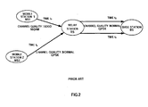
- FIG.3 shows a case where MS2 (mobile station 2) joins in where MS1 (mobile station 1) is communicating with a BS (base station) via a RS (relay station).
- MS2 mobile station 2
- BS base station
- RS relay station
- the MS2 Upon newly joining in, the MS2 transmits a pilot signal (non-regenerative relay pilot) for measuring channel quality between the MS2 and the BS via the RS (MS2-RS-BS channel quality) and a pilot signal (regenerative relay pilot 1) for measuring channel quality between the MS2 and the RS (MS2-RS channel quality), to the RS.
- a pilot signal non-regenerative relay pilot
- regenerative relay pilot 1 for measuring channel quality between the MS2 and the RS (MS2-RS channel quality
- the MS2 adds a flag indicative of non-regenerative relay pilot and a flag indicative of regenerative relay pilot 1 to these pilot signals.
- the transmission order of non-regenerative relay pilot and regenerative relay pilot 1 is not limited.
- the RS receiving these two kinds of pilot signals performs non-regenerative relay pilot processing on non-regenerative relay pilot to transmit to the BS.
- the RS maintains the MCS and amplifies the non-regenerative relay pilot and transmits the result to the BS.
- the RS measures the received quality (MS2-RS channel quality) of regenerative relay pilot 1, and transmits channel quality information to the BS.
- the RS transmits a new pilot signal (regenerative relay pilot 2) for measurement of channel quality of a channel between the RS and the BS (RS-BS channel quality) to the BS.
- the RS adds a flag indicative of regenerative relay pilot 2 to regenerative relay pilot 2.
- the B S measures the received quality (MS2-RS-BS channel quality) of the non-regenerative relay pilot. Further, the BS measures the received quality (RS-BS channel quality) of regenerative relay pilot 2.
- the BS obtains the MS2-RS-BS channel quality as the channel quality of non-regenerative relay, and obtains the RS-BS channel quality as the channel quality of regenerative relay. Furthermore, the BS obtains the MS2-RS channel quality as the channel quality of regenerative relay from the received channel quality information.
- the BS determines the relay scheme of the RS (whether the RS performs regenerative relay or non-regenerative relay) and MCS in multi-hop communication. The determination results are transmitted to the RS as relay information. Further, this relay information is also transmitted to the MS2 via the RS.
- the MS2 encodes and modulates uplink data with the MCS based on the relay information and transmits the result to the RS.
- the RS switches between non-regenerative relay and regenerative relay based on the relay information and relays uplink data.
- the RS maintains the MCS, and amplifies uplink data and transmits the result to the BS.
- the RS once demodulates and decodes uplink data, and encodes and modulates the uplink data again with the MCS based on the relay information and transmits the result to the BS.
- FIG.4 illustrates the configuration of the BS.
- non-regenerative relay pilot, regenerative relay pilot 2, channel quality information and uplink data, received via antenna 101 are subjected to radio processing such as down-conversion in RF receiving section 102.
- radio processing such as down-conversion in RF receiving section 102.
- non-regenerative relay pilot and regenerative relay pilot 2 are inputted to received quality measuring section 103, and the channel quality information and uplink data are inputted to demodulation section 105.
- the channel quality information and the uplink data are demodulated in demodulation section 105 and decoded in decoding section 106 according to the MCS determined in determining section 104.
- the received data is thereby obtained.
- the decoded channel quality information (MS2-RS channel quality) is inputted to determining section 104.
- received quality measuring section 103 measures the received quality of non-regenerative relay pilot and regenerative relay pilot 2, and obtains the MS2-RS-BS channel quality and RS-BS channel quality. These kinds of channel quality are inputted to determining section 104. In addition, received quality measuring section 103 is able to distinguish between the non-regenerative relay pilot and regenerative relay pilot 2 by the flags added to the pilot signals.
- Determining section 104 determines the relay scheme of the RS and MCS in multi-hop communication from the MS2-RS-BS channel quality, MS2-RS channel quality and RS-BSchannelquality. The determination method will be described later.
- the determination results (the relay scheme and MCS) are inputted to coding section 107 as relay information.
- the relay information and the transmission data are encoded in coding section 107 and modulated in modulation section 108 according to the MCS determined in determining section 104.
- the modulated relay information and the downlink data are subjected to radio processing such as up-conversion in RF transmitting section 109 and then transmitted via antenna 101.
- the received SNR is used as channel quality in the following descriptions.
- determining section 104 classifies channel quality into three stages of "good”, “normal”, and “poor,” as shown in FIG. 5 .
- 16QAM is "good”
- QPSK is "normal”
- BPSK is "poor”.
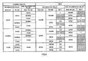
- determining section 104 refers to a table as shown in FIG.6 , and determines the relay scheme and MCS according to the combination of the MS2-RS channel quality, RS-BS channel quality and MS2-RS-BS channel quality. Determination results are given as relay information of one of "0" to "5" (information of three bits between "000” and "101").
- the table of FIG.6 shows modulation schemes alone as MCS, without spreading factors, for ease of explanation.
- the transmission rate “bit/T” indicates the number of bits that can be transmitted per unit time T.
- the transmission rate is assumed to be 1 bit/T in the case that QPSK is used both in MS2-RS and RS-BS. Since the number of bits that can be transmitted per symbol in 16QAM is twice that in QPSK, the transmission rate is 2 bits/T when in both MS2-RS and RS-BS 16QAM is used. Furthermore, since the number of bits that can be transmitted per symbol in BPSK is half that in QPSK, the transmission rate is 0.5 bits/T when in both MS2-RS and RS-BS BPSK is used.
- regenerative relay has defects that the relay processing needs much time and that the delay by the relay is large as compared with non-regenerative relay.
- regenerative relay requires the processing time twice that of non-regenerative relay.
- the transmission rate is 2 bits/T, and is twice the bit rate in the case of QPSK both in MS2-RS and RS-BS in regenerative relay.
- the number of bits that can be transmitted per unit time in regenerative relay is half that in non-regenerative relay.
- FIG.7 it is understood that it is possible to secure the transmission rate at or greater than optimal transmission rates (2 bits/T) of regenerative relay when the channel quality of non-regenerative relay is "normal" or more, and it is possible to combine the table of FIG.7 and the table of FIG.8 into a table as shown in FIG.9 .
- the table of FIG.9 is prepared on the premise that poorer channel quality in regenerative relay is not poorer than channel quality in non-regenerative relay because, in non-regenerative relay, noise is also amplified, while, in regenerative relay, recoding and remodulation are performed in accordance with channel quality.
- the MS2-RS channel quality is “good” and the RS-BS channel quality is “poor” in regenerative relay
- the MS2-RS-BS channel quality is unlikely to be “normal” or better in non-regenerative relay. Therefore, when the MS-RS channel quality is "good” and the RS-BS channel is "poor” in non-regenerative relay, the table of FIG.9 omits "good” and "normal” for the MS2-RS-BS channel quality in non-regenerative relay.
- the table of FIG.6 collectively shows selected combinations of relay schemes and MCS that obtain better transmission rates among the same combinations of three kinds of channel quality.
- the transmission rate is the same in the same combinations of channel quality (for example, in the table of FIG.9 , in the case where the MS2-RS channel quality is "good”, the RS-BS channel quality is "good”, the MS2-RS-BS channel quality is "normal” and the transmission rate is 2 bits/T in regenerative relay and in non-regenerative relay)
- non-regenerative relay is selected taking into account the fact that the processing load of the relay station is less in non-regenerative relay than in regenerative relay.
- FIG.10 illustrates the configuration of the RS.
- the relay information (information indicative of the combination of the relay scheme and MCS), pilot signals (regenerative relay pilot 1 and non-regenerative relay pilot) and uplink data received in antenna 201 are subjected to radio processing such as down-conversion and the like in RF receiving section 202.
- the relay information is received from the BS, and the pilot signals and uplink data are received from the MS2.
- the pilot signals are inputted to pilot decision section 203, and the relay information and uplink data are inputted to switching section 205.
- decision section 203 determines whether the pilot is regenerative relay pilot 1 or non-regenerative pilot, and inputs regenerative relay pilot 1 to received quality measuring section 204, while inputting non-regenerative relay pilot to amplifying section 206.
- Received quality measuring section 204 measures the received quality of regenerative relay pilot 1, and obtains the MS2-RS channel quality. Then, the channel quality information indicating the obtained channel quality is inputted to coding section 209.
- Switching section 205 has a table (part of the table of FIG.6 ) indicative of the relationships between relay information and relay schemes/MCS, and, according to input relay information, selects a combination of the relay scheme and MCS and switches regenerative relay and non-regenerative relay. For example, referring to the table of FIG.6 , when relay information is "1", the RS relays data by non-regenerative relay, and QPSK is used both in MS2-RS and RS-BS. Accordingly, when relay information is "1", since the RS relays data by non-regenerative relay, uplink data is inputted to amplifying section 206.
- uplink data is inputted to demodulation section 207.
- switching section 205 inputs information about the selected MCS to demodulation section 207, decoding section 208, coding section 209 and modulation section 210.
- Amplifying section 206 amplifies the uplink data and non-regenerative relay pilot to inputted to RF transmitting section 211.
- the uplink data inputted to demodulation section 207 is demodulated in demodulation section 207 and decoded in decoding 208 according to the MCS of MS2-RS designated by switching section 205.
- the result is encoded again in coding section 209 and modulated again in modulation section 210 according to the MCS of RS-BS designated by switching section 205.
- the modulated uplink data is inputted to RF transmitting section 211.
- channel quality information and regenerative relay pilot 2 are encoded in coding section 209, modulated in modulation section 210, and then inputted to RF transmitting section 211.
- the uplink data (to be relayed in regenerative relay) inputted frommodulation section 210 and the uplink data (to be relayed in non-regenerative relay) inputted from amplifying section 206 are subjected to radio processing such as up-conversion in RF transmitting section 211 and then transmitted to the BS via antenna 201. Further, channel quality information, regenerative relay pilot 2 and non-regenerative relay pilot are also subjected to radio processing such as up-conversion in RF transmitting section 211, and then transmitted to the BS via antenna 201. In addition, the relay information is transmitted to the MS2 in the relay scheme for the downlink data switched in the same way as uplink data.
- non-regenerative relay is adopted only when the RS-BS channel quality in regenerative relay is the same as the MS-RS-BS channel quality in non-regenerative relay.
- the RS-BS channel quality is better than the MS-RS channel quality when regenerative relay is employed, it is possible to make the transmission rate between the RS and BS better than the transmission rate between the MS and the RS.
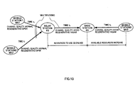
- FIG.13 it is possible to multiplex the data of MS1-RS and the data of MS2-RS and transmit, and, as a result, it is possible to reduce the resources used between the RS and the BS. Further, by reducing the resources used between the RS and the BS, resources that can be used by another MS (MS3) connecting with the BS increase, and it is thus possible to further improve system throughput.
- MS3 MS
- channel quality (MS2-RS channel quality and RS-BS channel quality) in regenerative relay and the channel quality (MS-RS-BS channel quality) in non-regenerative relay channel quality (MS2-BS channel quality) in the case of direct connection between the MS2 and the BS without using the RS is also notified to the BS, and, from these kinds of channel quality, the BS determines one of direct connection, regenerative relay and non-regenerative relay to perform between the MS2 and B2 and MCS.
- relay information is set for "0" irrespective of the MCS.
- the RS determines MCS between the MS and the RS.
- FIG.15 shows a case where the MS2 newly joins in while communication is in progress between the MS1 and the BS via the RS.
- the following descriptions will be limited to uplink data multi-hop communication, but downlink data multi-hop communication is performed in the same manner as with uplink data.
- the MS2 Upon newly joining in, the MS2 transmits a pilot signal to measure both the MS2-RS channel quality and MS2-RS-BS channel quality to the RS.
- This pilot signal is a pilot shared between regenerative relay and non-regenerative relay, and so the flag for distinguishing between the regenerative relay pilot and the non-regenerative relay pilot is not added.
- the RS receiving this pilot signal performs non-regenerative relay processing on the pilot to transmit to the BS as a non-regenerative relay pilot.
- the RS maintains the MCS and amplifies the pilot and transmits the result to the BS.
- the RS adds a flag indicative of non-regenerative relay pilot to non-regenerative relay pilot.
- the RS measures the received quality (MS2-RS channel quality) of the received pilot, and, according to the channel quality, selects the MCS for between the MS2 and the RS in regenerative relay.
- the RS selects 16QAM when the channel quality is "good", QPSK when the channel quality is "normal", or BPSK when the channel quality is "poor".
- the selection result is transmitted to the MS2 as MCS information. Further, the RS transmits a new pilot signal (regenerative relay pilot) to measure the RS-BS channel quality to the BS. At this point, the RS adds a flag indicative of regenerative relay pilot to regenerative relay pilot.
- regenerative relay pilot a new pilot signal
- the B S measures the received quality (MS2-RS-BS channel quality) of non-regenerative relay pilot. Further, the BS measures the received quality (RS-BS channel quality) of regenerative relay pilot.
- the BS obtains the MS2-RS-BS channel quality as the channel quality of non-regenerative relay, and further obtains the RS-BS channel quality as the channel quality of regenerative relay.
- the BS determines the relay scheme for the RS (whether the RS performs regenerative relay or non-regenerative relay), and further determines the MCS for between the RS and the BS in regenerative relay or determines the MCS for between the MS2 and the BS via the RS in non-regenerative relay.
- the determination result is transmitted to the RS as relay information. Further, this relay information is also transmitted to the MS2 via the RS.
- the MS2 performs coding and modulation on the uplink data with the MCS based on the MCS information transmitted from the RS to transmit to the RS. Meanwhile, in the case of non-regenerative relay, the MS2 performs coding and modulation on the uplink data with the MCS based on the relay information transmitted from the BS to transmit to the RS.
- the RS switches non-regenerative relay and regenerative relay based on the relay information to relay the uplink data.
- the RS maintains the MCS and amplifies the uplink data and transmits the result to the BS.
- the RS once demodulates and decodes the uplink data with the MCS determined by the RS, and performs coding and modulation again on the uplink data with the MCS based on the relay information to transmit to the BS.
- the RS once demodulates and decodes the downlink data from the BS, and performs coding and modulation again on the downlink data with the MCS determined by the RS to transmit to the MS2.
- FIG.16 illustrates the configuration of the BS.
- non-regenerative relay pilot, regenerative relay pilot and uplink data received via antenna 301 are subjected to radio processing such as down-conversion in RF receiving section 302. After the radio processing, non-regenerative relay pilot and regenerative relay pilot are inputted to received quality measuring section 303, and the uplink data is inputted to demodulation section 305.
- the uplink data is demodulated in demodulation section 305 and decoded in decoding section 306 according to MCS determined in determining section 304.
- the received data is thereby obtained.
- received quality measuring section 303 measures the received quality of non-regenerative relay pilot and regenerative relay pilot, and obtains the MS2-RS-BS channel quality and RS-BS channel quality. These kinds of channel quality are inputted to determining section 304.
- received quality measuring section 303 is capable of distinguishing between the non-regenerative relay pilot and the regenerative relay pilot by the flag added to each pilot.
- Determining section 304 determines the relay scheme of the RS and MCS from the MS2-RS-BS channel quality and RS-BSchannelquality. The determination method will be described later.
- the determination results are inputted to coding section 307 as relay information.
- the relay information and transmission data are encoded in coding section 307 and modulated in modulation section 308 according to the MCS determined in determining section 304.
- the modulated relay information and downlink data are subjected to radio processing such as up-conversion in RF transmitting section 309, and transmitted via antenna 301.
- the received SNR is used as channel quality in the following descriptions.
- determining section 304 classifies channel quality into three stages, "good”, “normal”, and “poor,” as shown in FIG.5 .
- 16QAM is “good”
- QPSK is "normal”
- BPSK is "poor”.
- determining section 304 refers to the table shown in FIG.17 , and determines the relay scheme and MCS corresponding according to the combination of the RS-BS channel quality and MS2-RS-BS channel quality. Determination results are given as relay information of one of "0" to "4" (information of three bits between "000” and "100").
- the table of FIG.17 shows modulation schemes alone as MCS, without spreading factors, for ease of explanation.
- the table of FIG.17 collectively shows selected combinations of the relay scheme and MCS that obtain optimal transmission rates for combinations of the RS-BS channel quality and the MS2-RS-BS channel quality.
- optimal transmission rates for the same combination of channel quality (for example, in the table of FIG.9 , in the case where the RS-BS channel quality is "good”, the MS2-RS-BS channel quality is "normal”, and the optimal transmission rate is 2 bits/T in both regenerative relay and non-regenerative relay)
- non-regenerative relay is selected taking into account the fact that the processing load of the relay station is less in non-regenerative relay than in regenerative relay.
- the RS determines the MCS for between the MS2 and the RS according to the MS2-RS channel quality. For example, when the RS-BS channel quality is "good” or "normal", and the MS2-RS-BS channel quality is "poor", the optimal transmission rate is obtained in regenerative relay.
- the MCS for between the MS2 and the RS is determined by the RS according to the MS2-RS channel quality.
- FIG.18 illustrates the configuration of the RS.
- the relay information, pilot signal and uplink data received in antenna 401 are subjected to radio processing such as down-conversion in RF receiving section 402.
- radio processing such as down-conversion in RF receiving section 402.
- the pilot signal is inputted to received quality measuring section 403 and amplifying section 406, and the relay information and uplink data are inputted to switching section 405.
- the relay information is received from the BS, and the pilot and uplink data are received from the MS2.
- Received quality measuring section 403 measures the received quality of the pilot, and obtains the MS2-RS channel quality.
- MCS determining section 404 determines the MCS for between the MS2 and the RS, and inputs MCS information to demodulation section 407 and decoding section 408. Further, the MCS information for between the MS2 and the RS is inputted to coding section 409 to be notified to the MS2.
- Switching section 405 has a table (part of the table of FIG.17 ) indicative of the relationships between relay information and relay schemes/MCS, and, according to input relay information, selects a combination of a relay scheme and MCS to switch regenerative relay and non-regenerative relay.
- a table part of the table of FIG.17
- uplink data is inputted to amplifying section 406.
- uplink data is inputted to demodulation section 407.
- Amplifying section 406 amplifies uplink data and pilot to input to RF transmitting section 411.
- the uplink data inputted to demodulation section 407 is demodulated in demodulation section 407 and decoded in decoding 408 according to the MCS of MS2-RS designated by MCS determining section 404.
- the result is encoded again in coding section 409 and modulated again in modulation section 410 according to the MCS of RS-BS designated by switching section 405.
- the modulated uplink data is inputted to RF transmitting section 411.
- regenerative relay pilot and the MCS information of MS2-RS are encoded in coding section 409, modulated in modulation section 410, and inputted to RF transmitting section 411.
- the uplink data (to be relayed in regenerative relay) inputted frommodulation section 410 and the uplink data (to be relayed in non-regenerative relay) inputted from amplifying section 406 are subjected to radio processing such as up-conversion in RF transmitting section 411, and transmitted to the BS via antenna 401. Further, regenerative relay pilot, and the pilot (non-regenerative relay pilot) amplified in amplifying section 406 are also subjected to the radio processing such as up-conversion in RF transmitting section 411, and transmitted to the BS via antenna 401.
- the MCS information of MS2-RS is subjected to the radio processing such as up-conversion in RF transmitting section 411, and transmitted to the MS2 via antenna 401.
- the relay information is transmitted to the MS2 in the relay scheme of the downlink data switched in the same way as in the uplink data.
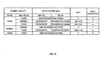
- Embodiment 1 when multiplexing schemes such as CDM and SDM are used in communications between the MS and the RS, it is also possible to use the table shown in FIG.19 instead of the table in FIG.17 .
- the table shown in FIG.19 as in Embodiment 1, non-regenerative relay is adopted only when the RS-BS channel quality in regenerative relay is the same as the MS-RS-BS channel quality in non-regenerative relay.
- the MS2 is present in the service area of the BS, as in Embodiment 1, it is also possible to use a table as shown in FIG.20 , instead of the table of FIG.17 .
- Embodiment 1 it is possible to improve system throughput, while preventing the user throughput from decreasing. Further, in this Embodiment, the RS determines the MCS for between the MS and the RS in regenerative relay. Therefore, as compared with Embodiment 1, it is possible to decrease the number of pilots that the MS transmits, while the need is eliminated of the RS transmitting the BS-RS channel quality to the BS, and the system throughput can thus be further increased.
- the relay station or mobile station may hold the reference table to determine the relay scheme and MCS.
- Each function block employed in the description of each of the aforementioned embodiments may typically be implemented as an LSI constituted by an integrated circuit. These may be individual chips or partially or totally contained on a single chip.
- LSI is adopted here but this may also be referred to as “IC”, “system LSI”, “super LSI”, or “ultra LSI” depending on differing extents of integration.
- circuit integration is not limited to LSI's, and implementation using dedicated circuitry or general purpose processors is also possible.
- FPGA Field Programmable Gate Array
- reconfigurable processor where connections and settings of circuit cells within an LSI can be reconfigured is also possible.
- the present invention is suitable for use in a mobile communication system using a high-frequency radio band.
Landscapes
- Engineering & Computer Science (AREA)
- Computer Networks & Wireless Communication (AREA)
- Signal Processing (AREA)
- Quality & Reliability (AREA)
- Mobile Radio Communication Systems (AREA)
- Radio Relay Systems (AREA)
Description
- The present invention relates to a wireless communication system.
- In recent years, wireless cellular systems typified by cellular telephone systems and the like have diversified their service patterns, and have been demanded to transmit large-capacity data such as static images, moving pictures and the like as well as speech data. To meet such demands, it has been studied actively to transmit large-capacity data using a high-frequency radio band.
- In using high-frequency radio band, the degree of attenuation due to the transmission distance becomes a problem. In other words, high transmission rates are obtained at locations near the transmitting station, but only low transmission rates are achieved at locations a predetermined distance or more apart from the transmitting station. Accordingly, to consider the actual operations of the communication system, it is necessary to cover a service area by installing a large number of base stations. However, installation of a large number of base stations requires significant cost. From such circumstances, a technique is strongly demanded that implements large-capacity communication service without increasing the number of base stations to install.
- There is multi-hop communication, as one of methods for expanding the service area of a base station. This technique is a communication technique where a relay station installed in the base station service area relays and transmits a signal of a mobile station out of the service area to the base station (for example, see Non-Patent Document 1).
- Multi-hop communication is broadly divided into regenerative relay and non-regenerative relay. In regenerative relay, a relay station once demodulates and decodes a received signal, encodes and modulates the signal again using a modulation scheme and coding rate (Modulation and Coding Scheme: MCS) in accordance with channel quality, and then transmits the result. In contrast, in non-regenerative relay, the relay station amplifies a received signal and transmits the signal without change. In comparison with non-regenerative relay, regenerative relay provides an advantage of enabling a relay using an adequate MCS in accordance with channel quality, yet also has a disadvantage of increasing the delay due to relay. Meanwhile, non-regenerative relay provides an advantage of decreasing the delay due to relay yet also has a disadvantage of making the SNR degrade by amplifying noise. Non-patent Document 1: Hasegawa et al. "Multi-hop System for Adaptive Modulation using Regenerating Fixed Hop Stations" Technical Report of IEICE, October 2004, A/P 2004-189, RCS2004-210, pp.57-61.
-
US 2004/0198467 A1 presents a method for reducing power consumption in a multi-hop wireless communications network including a plurality of nodes. At a source node, a first power requirement for relaying a signal to a destination node through an intermediate node using an amplification mode is determined. A second power requirement for relaying the signal of the destination node through the intermediate node using a regeneration mode is also determined at the source node. A relay request message is transmitted to the intermediate node, wherein the relay request message includes the first and second power requirements. Furthermore, each node includes a transmit block and a receive block, as well as a mode selector. The mode selector controls a switch so as to either activate the regeneration mode or the relay mode. -
WO 2004/107693 A1 presents a method for performing communication in a two-hop wireless communication network, wherein a transmitter, a receiver and at least one relay station are engaged in a communication session. The relay station forwards signals from a first link between the transmitter and the relay stations to a second link between the relay stations and the receiver. The forwarding performed by the at least one relay station is adapted as a response to estimated radio channel characteristics of the first link or both, the first and the second link. - In regenerative relay in multi-hop communication, the throughput may decrease as the number of mobile stations using a single relay station increases. For example, when mobile station 1 (MS1) is communicating with a base station (BS) via a relay station (RS) by regenerative relay as shown in
FIG.1 , and mobile station 2 (MS2) joins in as shown inFIG.2 , since communication occasions ofmobile station 1 decrease due to relay processing formobile station 2, user throughput ofmobile station 1 decreases. Further, as shown inFIG.2 , when the channel quality betweenmobile station 2 and the relay station is poorer than the channel quality betweenmobile station 1 and the relay station, system throughput (average transmission rate of the entire system) is lower than beforemobile station 2 joins in. - In view of these respects, it is an object of the present invention to provide a wireless communication system that maintains system throughput and prevents a decrease in user throughput in multi-hop communication.
- The invention is defined by the independent claims.
- According to the invention, it is possible to maintain system throughput and prevent a decrease in user throughput.
-
-
FIG.1 is a schematic diagram of a conventional multi-hop communication system; -
FIG.2 is another schematic diagram of the conventional multi-hop communication system; -
FIG.3 is an operation sequence in a multi-hop communication system according toEmbodiment 1 of the invention; -
FIG.4 is a block diagram illustrating a configuration of a base station according toEmbodiment 1 of the invention; -
FIG. 5 is classification of channel quality according toEmbodiment 1 of the invention; -
FIG.6 is a reference table according toEmbodiment 1 of the invention; -
FIG.7 is a table showing relationship between the channel quality and MCS in a regenerative relay according toEmbodiment 1 of the invention; -
FIG.8 is a table showing relationship between the channel quality and MCS in a non-regenerative relay according toEmbodiment 1 of the invention; -
FIG.9 is a table obtained by combining the table as shown inFIG.7 and the table as shown inFIG.8 ; -
FIG.10 is a block diagram illustrating a configuration of a relay station according toEmbodiment 1 of the invention; -
FIG.11 is a schematic diagram illustrating the multi-hop communication system according toEmbodiment 1 of the invention; -
FIG.12 is another reference table according toEmbodiment 1 of the invention; -
FIG.13 is another schematic diagram illustrating the multi-hop communication system according toEmbodiment 1 of the invention; -
FIG.14 is still another reference table according toEmbodiment 1 of the invention; -
FIG.15 is an operation sequence in a multi-hop communication system according toEmbodiment 2 of the invention; -
FIG.16 is a block diagram illustrating a configuration of a base station according toEmbodiment 2 of the invention; -
FIG.17 is a reference table according toEmbodiment 2 of the invention; -
FIG.18 is a block diagram illustrating a configuration of a relay station according toEmbodiment 2 of the invention; -
FIG.19 is another reference table according toEmbodiment 2 of the invention; and -
FIG.20 is still another reference table according toEmbodiment 2 of the invention. - Embodiments of the present invention will be descried below in detail with reference to accompanying drawings.
- In this Embodiment, a base station determines the relay scheme and MCS taking into account both the channel quality of regenerative relay and the channel quality of non-regenerative relay.
- Described first is an operation sequence in a multi-hop communication system according to this Embodiment. The operation sequence is shown in
FIG.3. FIG.3 shows a case where MS2 (mobile station 2) joins in where MS1 (mobile station 1) is communicating with a BS (base station) via a RS (relay station). In addition, to avoid complexity in descriptions, the following descriptions are limited to uplink data multi-hop communication, but downlink data multi-hop communication is performed as with uplink data. - Upon newly joining in, the MS2 transmits a pilot signal (non-regenerative relay pilot) for measuring channel quality between the MS2 and the BS via the RS (MS2-RS-BS channel quality) and a pilot signal (regenerative relay pilot 1) for measuring channel quality between the MS2 and the RS (MS2-RS channel quality), to the RS. At this point, the MS2 adds a flag indicative of non-regenerative relay pilot and a flag indicative of
regenerative relay pilot 1 to these pilot signals. In addition, the transmission order of non-regenerative relay pilot andregenerative relay pilot 1 is not limited. - The RS receiving these two kinds of pilot signals performs non-regenerative relay pilot processing on non-regenerative relay pilot to transmit to the BS. In other words, the RS maintains the MCS and amplifies the non-regenerative relay pilot and transmits the result to the BS. Further, the RS measures the received quality (MS2-RS channel quality) of
regenerative relay pilot 1, and transmits channel quality information to the BS. Furthermore, the RS transmits a new pilot signal (regenerative relay pilot 2) for measurement of channel quality of a channel between the RS and the BS (RS-BS channel quality) to the BS. At this point, the RS adds a flag indicative ofregenerative relay pilot 2 toregenerative relay pilot 2. - Next, the BS measures the received quality (MS2-RS-BS channel quality) of the non-regenerative relay pilot. Further, the BS measures the received quality (RS-BS channel quality) of
regenerative relay pilot 2. By this means, the BS obtains the MS2-RS-BS channel quality as the channel quality of non-regenerative relay, and obtains the RS-BS channel quality as the channel quality of regenerative relay. Furthermore, the BS obtains the MS2-RS channel quality as the channel quality of regenerative relay from the received channel quality information. Then, based on these three kinds of channel quality, the BS determines the relay scheme of the RS (whether the RS performs regenerative relay or non-regenerative relay) and MCS in multi-hop communication. The determination results are transmitted to the RS as relay information. Further, this relay information is also transmitted to the MS2 via the RS. - The MS2 encodes and modulates uplink data with the MCS based on the relay information and transmits the result to the RS.
- The RS switches between non-regenerative relay and regenerative relay based on the relay information and relays uplink data. In other words, in the case of non-regenerative relay, the RS maintains the MCS, and amplifies uplink data and transmits the result to the BS. Meanwhile, in the case of regenerative relay, the RS once demodulates and decodes uplink data, and encodes and modulates the uplink data again with the MCS based on the relay information and transmits the result to the BS.
- Described next is a configuration of the BS (base station) according to this Embodiment.
FIG.4 illustrates the configuration of the BS. - In
BS 200 shown inFIG.4 , non-regenerative relay pilot,regenerative relay pilot 2, channel quality information and uplink data, received viaantenna 101, are subjected to radio processing such as down-conversion inRF receiving section 102. After the radio processing, non-regenerative relay pilot andregenerative relay pilot 2 are inputted to receivedquality measuring section 103, and the channel quality information and uplink data are inputted todemodulation section 105. - The channel quality information and the uplink data are demodulated in
demodulation section 105 and decoded indecoding section 106 according to the MCS determined in determining section 104. The received data is thereby obtained. Further, the decoded channel quality information (MS2-RS channel quality) is inputted to determining section 104. - Meanwhile, received
quality measuring section 103 measures the received quality of non-regenerative relay pilot andregenerative relay pilot 2, and obtains the MS2-RS-BS channel quality and RS-BS channel quality. These kinds of channel quality are inputted to determining section 104. In addition, receivedquality measuring section 103 is able to distinguish between the non-regenerative relay pilot andregenerative relay pilot 2 by the flags added to the pilot signals. - Determining section 104 determines the relay scheme of the RS and MCS in multi-hop communication from the MS2-RS-BS channel quality, MS2-RS channel quality and RS-BSchannelquality. The determination method will be described later. The determination results (the relay scheme and MCS) are inputted to
coding section 107 as relay information. - The relay information and the transmission data (downlink data) are encoded in
coding section 107 and modulated inmodulation section 108 according to the MCS determined in determining section 104. The modulated relay information and the downlink data are subjected to radio processing such as up-conversion inRF transmitting section 109 and then transmitted viaantenna 101. - Described next is the method of determining the relay scheme and MCS. In addition, the received SNR is used as channel quality in the following descriptions.
- First, determining section 104 classifies channel quality into three stages of "good", "normal", and "poor," as shown in
FIG. 5 . For the modulation scheme capable of communication in each state, 16QAM is "good", QPSK is "normal", and BPSK is "poor". - Next, determining section 104 refers to a table as shown in
FIG.6 , and determines the relay scheme and MCS according to the combination of the MS2-RS channel quality, RS-BS channel quality and MS2-RS-BS channel quality. Determination results are given as relay information of one of "0" to "5" (information of three bits between "000" and "101"). In addition, the table ofFIG.6 shows modulation schemes alone as MCS, without spreading factors, for ease of explanation. - In
FIG.6 , for example, when the MS2-RS channel quality is "good", RS-BS channel quality is "good" and MS2-RS-BS channel quality is "normal", it is determined that the relay scheme is non-regenerative relay, and that the modulation scheme is QPSK, and relay information "1" corresponding to this determination result is transmitted. Further, for example, when the MS2-RS channel quality is "normal", RS-BS channel quality is "good" and MS2-RS-BS channel quality is "poor", it is determined that the relay scheme is regenerative relay, and that the modulation scheme is QPSK between the MS2 and RS (MS2-RS), while being 16QAM between the R2 and BS (RS-BS), and the relay information "3" corresponding to this determination result is transmitted. - Described herein are grounds for generation of the table as shown in
FIG.6 . - First, the relationships between channel quality and MCS in regenerative relay are shown in the table of
FIG.7 . According to these relationships between the channel quality and MCS, "good" refers to 16QAM, "normal" refers to QPSK and "poor" refers to BPSK. Further, the transmission rate "bit/T" indicates the number of bits that can be transmitted per unit time T. Herein, the transmission rate is assumed to be 1 bit/T in the case that QPSK is used both in MS2-RS and RS-BS. Since the number of bits that can be transmitted per symbol in 16QAM is twice that in QPSK, the transmission rate is 2 bits/T when in both MS2-RS and RS-BS 16QAM is used. Furthermore, since the number of bits that can be transmitted per symbol in BPSK is half that in QPSK, the transmission rate is 0.5 bits/T when in both MS2-RS and RS-BS BPSK is used. - Similarly, the relationships between channel quality and MCS in non-regenerative relay are shown in the table of
FIG.8 . As described above, regenerative relay has defects that the relay processing needs much time and that the delay by the relay is large as compared with non-regenerative relay. Herein, it is assumed that regenerative relay requires the processing time twice that of non-regenerative relay. Accordingly, when the MCS of MS2-RS-BS is QPSK, the transmission rate is 2 bits/T, and is twice the bit rate in the case of QPSK both in MS2-RS and RS-BS in regenerative relay. In other words, when the same modulation scheme is selected in regenerative relay and non-regenerative relay, the number of bits that can be transmitted per unit time in regenerative relay is half that in non-regenerative relay. - Herein, by comparing
FIG.7 withFIG.8 , it is understood that it is possible to secure the transmission rate at or greater than optimal transmission rates (2 bits/T) of regenerative relay when the channel quality of non-regenerative relay is "normal" or more, and it is possible to combine the table ofFIG.7 and the table ofFIG.8 into a table as shown inFIG.9 . However, the table ofFIG.9 is prepared on the premise that poorer channel quality in regenerative relay is not poorer than channel quality in non-regenerative relay because, in non-regenerative relay, noise is also amplified, while, in regenerative relay, recoding and remodulation are performed in accordance with channel quality. For example, when the MS2-RS channel quality is "good" and the RS-BS channel quality is "poor" in regenerative relay, the MS2-RS-BS channel quality is unlikely to be "normal" or better in non-regenerative relay. Therefore, when the MS-RS channel quality is "good" and the RS-BS channel is "poor" in non-regenerative relay, the table ofFIG.9 omits "good" and "normal" for the MS2-RS-BS channel quality in non-regenerative relay. - Then, based on the table of
FIG.9 , the table ofFIG.6 collectively shows selected combinations of relay schemes and MCS that obtain better transmission rates among the same combinations of three kinds of channel quality. In addition, when the transmission rate is the same in the same combinations of channel quality (for example, in the table ofFIG.9 , in the case where the MS2-RS channel quality is "good", the RS-BS channel quality is "good", the MS2-RS-BS channel quality is "normal" and the transmission rate is 2 bits/T in regenerative relay and in non-regenerative relay), non-regenerative relay is selected taking into account the fact that the processing load of the relay station is less in non-regenerative relay than in regenerative relay. - Accordingly, by selecting the combinations of relay schemes and MCS based on the table shown in
FIG.6 and by switching the relay schemes and MCS appropriately and performing relay, it is possible to perform multi-hop communication using optimal combinations in accordance with three kinds of channel quality for MS2-RS, RS-BS and MS2-RS-BS, that is, using combinations of relay scheme and MCS that can achieve optimal transmission rates in accordance with three kids of channel quality, so that, compared to conventional multi-hop communication where relay is always performed using only one relay scheme of either regenerative relay or non-regenerative relay, user throughput can be improved. - The configuration of the relay station (RS) according to this Embodiment will be described below.
FIG.10 illustrates the configuration of the RS. - In RS200 as shown in
FIG.10 , the relay information (information indicative of the combination of the relay scheme and MCS), pilot signals (regenerative relay pilot 1 and non-regenerative relay pilot) and uplink data received inantenna 201 are subjected to radio processing such as down-conversion and the like inRF receiving section 202. In addition, the relay information is received from the BS, and the pilot signals and uplink data are received from the MS2. After the radio processing, the pilot signals are inputted to pilotdecision section 203, and the relay information and uplink data are inputted to switchingsection 205. - Based on the flags added to the pilot signals,
decision section 203 determines whether the pilot isregenerative relay pilot 1 or non-regenerative pilot, and inputsregenerative relay pilot 1 to receivedquality measuring section 204, while inputting non-regenerative relay pilot to amplifyingsection 206. - Received
quality measuring section 204 measures the received quality ofregenerative relay pilot 1, and obtains the MS2-RS channel quality. Then, the channel quality information indicating the obtained channel quality is inputted tocoding section 209. -
Switching section 205 has a table (part of the table ofFIG.6 ) indicative of the relationships between relay information and relay schemes/MCS, and, according to input relay information, selects a combination of the relay scheme and MCS and switches regenerative relay and non-regenerative relay. For example, referring to the table ofFIG.6 , when relay information is "1", the RS relays data by non-regenerative relay, and QPSK is used both in MS2-RS and RS-BS. Accordingly, when relay information is "1", since the RS relays data by non-regenerative relay, uplink data is inputted to amplifyingsection 206. Meanwhile, for example, when relay information is "4", since the RS relays data by regenerative relay, and 16QAM is used in MS2-RS while QPSK is used in RS-BS, uplink data is inputted todemodulation section 207. Further, switchingsection 205 inputs information about the selected MCS todemodulation section 207, decodingsection 208,coding section 209 andmodulation section 210. - Amplifying
section 206 amplifies the uplink data and non-regenerative relay pilot to inputted toRF transmitting section 211. - Meanwhile, the uplink data inputted to
demodulation section 207 is demodulated indemodulation section 207 and decoded in decoding 208 according to the MCS of MS2-RS designated by switchingsection 205. The result is encoded again incoding section 209 and modulated again inmodulation section 210 according to the MCS of RS-BS designated by switchingsection 205. The modulated uplink data is inputted toRF transmitting section 211. - Meanwhile, channel quality information and
regenerative relay pilot 2 are encoded incoding section 209, modulated inmodulation section 210, and then inputted toRF transmitting section 211. - The uplink data (to be relayed in regenerative relay) inputted
frommodulation section 210 and the uplink data (to be relayed in non-regenerative relay) inputted from amplifyingsection 206 are subjected to radio processing such as up-conversion inRF transmitting section 211 and then transmitted to the BS viaantenna 201. Further, channel quality information,regenerative relay pilot 2 and non-regenerative relay pilot are also subjected to radio processing such as up-conversion inRF transmitting section 211, and then transmitted to the BS viaantenna 201. In addition, the relay information is transmitted to the MS2 in the relay scheme for the downlink data switched in the same way as uplink data. - As shown in
FIG.11 , with the above-described BS and RS, when a MS2 newly joins in while communication is in progress between a MS1 and a BS via a RS by regenerative relay, multi-hop communication is made possible for the MS2 using the combination (non-regenerative relay/QPSK inFIG.11 ) of a relay scheme and MCS capable of obtaining optimal transmission rates according to three kinds of channel quality, MS2-RS, RS-BS and MS2-RS-BS channel quality. Thus, by performing a relay capable of obtaining optimal transmission rates to the MS2, it is possible to maintain system throughput even when the MS2 newly joins in. Further, in particular, when non-regenerative relay is performed with the MS2, since the processing delay of non-regenerative relay is less than that of regenerative relay, communication occasions for the MS1 increase compared to the case of performing regenerative relay with the MS2, so that it is possible to prevent user throughput of the MS1 from decreasing. Furthermore, by decreases in the processing delay due to application of non-regenerative relay to the MS2, the system throughput can be increased. - In addition, when multiplexing schemes such as code division multiplex (CDM) and space division multiplex (SDM) are used in communications between the MS and RS, it is also possible to use the table shown in
FIG.12 instead of the table inFIG.6 . - In the table shown in
FIG.12 , non-regenerative relay is adopted only when the RS-BS channel quality in regenerative relay is the same as the MS-RS-BS channel quality in non-regenerative relay. By using such a table, when the RS-BS channel quality is better than the MS-RS channel quality when regenerative relay is employed, it is possible to make the transmission rate between the RS and BS better than the transmission rate between the MS and the RS. Accordingly, as shown inFIG.13 , it is possible to multiplex the data of MS1-RS and the data of MS2-RS and transmit, and, as a result, it is possible to reduce the resources used between the RS and the BS. Further, by reducing the resources used between the RS and the BS, resources that can be used by another MS (MS3) connecting with the BS increase, and it is thus possible to further improve system throughput. - Further, when the MS2 is present in the service area of the BS, it is also possible to use a table as shown in
FIG.14 , instead of the table ofFIG.6 . - In the table shown in
FIG.14 , in addition to the channel quality (MS2-RS channel quality and RS-BS channel quality) in regenerative relay and the channel quality (MS-RS-BS channel quality) in non-regenerative relay, channel quality (MS2-BS channel quality) in the case of direct connection between the MS2 and the BS without using the RS is also notified to the BS, and, from these kinds of channel quality, the BS determines one of direct connection, regenerative relay and non-regenerative relay to perform between the MS2 and B2 and MCS. In addition, in the case of direct connection, relay information is set for "0" irrespective of the MCS. By using such a table, when the channel quality is poor in communications via the RS, by directly connecting between the MS2 and the BS, it is possible to further improve system throughput. - In this Embodiment, in regenerative relay, the RS determines MCS between the MS and the RS.
- Described first is an operation sequence in a multi-hop communication system according to this Embodiment. The operation sequence is shown in
FIG.15. FIG.15 shows a case where the MS2 newly joins in while communication is in progress between the MS1 and the BS via the RS. In addition, to avoid complexity in descriptions, the following descriptions will be limited to uplink data multi-hop communication, but downlink data multi-hop communication is performed in the same manner as with uplink data. - Upon newly joining in, the MS2 transmits a pilot signal to measure both the MS2-RS channel quality and MS2-RS-BS channel quality to the RS. This pilot signal is a pilot shared between regenerative relay and non-regenerative relay, and so the flag for distinguishing between the regenerative relay pilot and the non-regenerative relay pilot is not added.
- The RS receiving this pilot signal performs non-regenerative relay processing on the pilot to transmit to the BS as a non-regenerative relay pilot. In other words, the RS maintains the MCS and amplifies the pilot and transmits the result to the BS. At this point, the RS adds a flag indicative of non-regenerative relay pilot to non-regenerative relay pilot. Further, the RS measures the received quality (MS2-RS channel quality) of the received pilot, and, according to the channel quality, selects the MCS for between the MS2 and the RS in regenerative relay. The RS selects 16QAM when the channel quality is "good", QPSK when the channel quality is "normal", or BPSK when the channel quality is "poor". The selection result is transmitted to the MS2 as MCS information. Further, the RS transmits a new pilot signal (regenerative relay pilot) to measure the RS-BS channel quality to the BS. At this point, the RS adds a flag indicative of regenerative relay pilot to regenerative relay pilot.
- Next, the BS measures the received quality (MS2-RS-BS channel quality) of non-regenerative relay pilot. Further, the BS measures the received quality (RS-BS channel quality) of regenerative relay pilot. By this means, the BS obtains the MS2-RS-BS channel quality as the channel quality of non-regenerative relay, and further obtains the RS-BS channel quality as the channel quality of regenerative relay. Then, based on these two kinds of channel quality, the BS determines the relay scheme for the RS (whether the RS performs regenerative relay or non-regenerative relay), and further determines the MCS for between the RS and the BS in regenerative relay or determines the MCS for between the MS2 and the BS via the RS in non-regenerative relay. The determination result is transmitted to the RS as relay information. Further, this relay information is also transmitted to the MS2 via the RS.
- In the case of regenerative relay, the MS2 performs coding and modulation on the uplink data with the MCS based on the MCS information transmitted from the RS to transmit to the RS. Meanwhile, in the case of non-regenerative relay, the MS2 performs coding and modulation on the uplink data with the MCS based on the relay information transmitted from the BS to transmit to the RS.
- The RS switches non-regenerative relay and regenerative relay based on the relay information to relay the uplink data. In other words, in the case of non-regenerative relay, the RS maintains the MCS and amplifies the uplink data and transmits the result to the BS. Meanwhile, in the case of regenerative relay, the RS once demodulates and decodes the uplink data with the MCS determined by the RS, and performs coding and modulation again on the uplink data with the MCS based on the relay information to transmit to the BS. In addition, for the downlink data, in the case of regenerative relay, the RS once demodulates and decodes the downlink data from the BS, and performs coding and modulation again on the downlink data with the MCS determined by the RS to transmit to the MS2.
- Described next is a configuration of the BS (base station) according to this Embodiment.
FIG.16 illustrates the configuration of the BS. - In
BS 300 as shown inFIG.16 , non-regenerative relay pilot, regenerative relay pilot and uplink data received viaantenna 301 are subjected to radio processing such as down-conversion inRF receiving section 302. After the radio processing, non-regenerative relay pilot and regenerative relay pilot are inputted to receivedquality measuring section 303, and the uplink data is inputted todemodulation section 305. - The uplink data is demodulated in
demodulation section 305 and decoded indecoding section 306 according to MCS determined in determiningsection 304. The received data is thereby obtained. - Meanwhile, received
quality measuring section 303 measures the received quality of non-regenerative relay pilot and regenerative relay pilot, and obtains the MS2-RS-BS channel quality and RS-BS channel quality. These kinds of channel quality are inputted to determiningsection 304. In addition, receivedquality measuring section 303 is capable of distinguishing between the non-regenerative relay pilot and the regenerative relay pilot by the flag added to each pilot. - Determining
section 304 determines the relay scheme of the RS and MCS from the MS2-RS-BS channel quality and RS-BSchannelquality. The determination method will be described later. The determination results (relay scheme and MCS) are inputted tocoding section 307 as relay information. - The relay information and transmission data (downlink data) are encoded in
coding section 307 and modulated inmodulation section 308 according to the MCS determined in determiningsection 304. The modulated relay information and downlink data are subjected to radio processing such as up-conversion inRF transmitting section 309, and transmitted viaantenna 301. - Described next is the method of determining the relay scheme and MCS. In addition, the received SNR is used as channel quality in the following descriptions.
- First, determining
section 304 classifies channel quality into three stages, "good", "normal", and "poor," as shown inFIG.5 . For the modulation scheme capable of communication in each state, 16QAM is "good", QPSK is "normal" and BPSK is "poor". - Next, determining
section 304 refers to the table shown inFIG.17 , and determines the relay scheme and MCS corresponding according to the combination of the RS-BS channel quality and MS2-RS-BS channel quality. Determination results are given as relay information of one of "0" to "4" (information of three bits between "000" and "100"). In addition, the table ofFIG.17 shows modulation schemes alone as MCS, without spreading factors, for ease of explanation. - Based on the table of
FIG.9 , the table ofFIG.17 collectively shows selected combinations of the relay scheme and MCS that obtain optimal transmission rates for combinations of the RS-BS channel quality and the MS2-RS-BS channel quality. In addition, whenaplurality of optimal transmission rates exist for the same combination of channel quality (for example, in the table ofFIG.9 , in the case where the RS-BS channel quality is "good", the MS2-RS-BS channel quality is "normal", and the optimal transmission rate is 2 bits/T in both regenerative relay and non-regenerative relay), non-regenerative relay is selected taking into account the fact that the processing load of the relay station is less in non-regenerative relay than in regenerative relay. - Further, when regenerative relay is selected as the relay scheme that obtains optimal transmission rates based on
FIG.9 , inFIG.17 , the RS determines the MCS for between the MS2 and the RS according to the MS2-RS channel quality. For example, when the RS-BS channel quality is "good" or "normal", and the MS2-RS-BS channel quality is "poor", the optimal transmission rate is obtained in regenerative relay. In addition, in this case, inFIG.17 , in contrast to the MCS for between the RS and the BS being selected based onFIG.9 , the MCS for between the MS2 and the RS is determined by the RS according to the MS2-RS channel quality. - The configuration of the RS (relay station) according to this Embodiment will be described below.
FIG.18 illustrates the configuration of the RS. - In RS400 as shown in
FIG.18 , the relay information, pilot signal and uplink data received inantenna 401 are subjected to radio processing such as down-conversion inRF receiving section 402. After the radio processing, the pilot signal is inputted to receivedquality measuring section 403 and amplifyingsection 406, and the relay information and uplink data are inputted to switchingsection 405. In addition, the relay information is received from the BS, and the pilot and uplink data are received from the MS2. - Received
quality measuring section 403 measures the received quality of the pilot, and obtains the MS2-RS channel quality. - Based on the MS2-RS channel quality,
MCS determining section 404 determines the MCS for between the MS2 and the RS, and inputs MCS information todemodulation section 407 anddecoding section 408. Further, the MCS information for between the MS2 and the RS is inputted tocoding section 409 to be notified to the MS2. -
Switching section 405 has a table (part of the table ofFIG.17 ) indicative of the relationships between relay information and relay schemes/MCS, and, according to input relay information, selects a combination of a relay scheme and MCS to switch regenerative relay and non-regenerative relay. In the case of non-regenerative relay, uplink data is inputted to amplifyingsection 406. In the case of regenerative relay, uplink data is inputted todemodulation section 407. - Amplifying
section 406 amplifies uplink data and pilot to input toRF transmitting section 411. - Meanwhile, the uplink data inputted to
demodulation section 407 is demodulated indemodulation section 407 and decoded in decoding 408 according to the MCS of MS2-RS designated byMCS determining section 404. The result is encoded again incoding section 409 and modulated again inmodulation section 410 according to the MCS of RS-BS designated by switchingsection 405. The modulated uplink data is inputted toRF transmitting section 411. - Meanwhile, regenerative relay pilot and the MCS information of MS2-RS are encoded in
coding section 409, modulated inmodulation section 410, and inputted toRF transmitting section 411. - The uplink data (to be relayed in regenerative relay) inputted
frommodulation section 410 and the uplink data (to be relayed in non-regenerative relay) inputted from amplifyingsection 406 are subjected to radio processing such as up-conversion inRF transmitting section 411, and transmitted to the BS viaantenna 401. Further, regenerative relay pilot, and the pilot (non-regenerative relay pilot) amplified in amplifyingsection 406 are also subjected to the radio processing such as up-conversion inRF transmitting section 411, and transmitted to the BS viaantenna 401. Furthermore, the MCS information of MS2-RS is subjected to the radio processing such as up-conversion inRF transmitting section 411, and transmitted to the MS2 viaantenna 401. In addition, the relay information is transmitted to the MS2 in the relay scheme of the downlink data switched in the same way as in the uplink data. - In addition, as in
Embodiment 1, when multiplexing schemes such as CDM and SDM are used in communications between the MS and the RS, it is also possible to use the table shown inFIG.19 instead of the table inFIG.17 . In the table shown inFIG.19 , as inEmbodiment 1, non-regenerative relay is adopted only when the RS-BS channel quality in regenerative relay is the same as the MS-RS-BS channel quality in non-regenerative relay. Further, when the MS2 is present in the service area of the BS, as inEmbodiment 1, it is also possible to use a table as shown inFIG.20 , instead of the table ofFIG.17 . - Thus, according to this Embodiment, as in
Embodiment 1, it is possible to improve system throughput, while preventing the user throughput from decreasing. Further, in this Embodiment, the RS determines the MCS for between the MS and the RS in regenerative relay. Therefore, as compared withEmbodiment 1, it is possible to decrease the number of pilots that the MS transmits, while the need is eliminated of the RS transmitting the BS-RS channel quality to the BS, and the system throughput can thus be further increased. - In addition, in the above-mentioned Embodiment, each table is generated so as to maximize the transmission rate, but it is possible to generate each table according to various requirements of the communication system, such as "meeting a data rate of minimum 1 Mbps", "transmission rate that meets BER=0.01 at SNR=15dB", and so on.
- Further, although examples have been explained in the above-mentioned Embodiments where the base station determines the relay scheme and MCS, the relay station or mobile station may hold the reference table to determine the relay scheme and MCS.
- Although with the above embodiments cases have been described where the present invention is configured by hardware, the present invention may be implemented by software.
- Each function block employed in the description of each of the aforementioned embodiments may typically be implemented as an LSI constituted by an integrated circuit. These may be individual chips or partially or totally contained on a single chip.
- "LSI" is adopted here but this may also be referred to as "IC", "system LSI", "super LSI", or "ultra LSI" depending on differing extents of integration.
- Further, the method of circuit integration is not limited to LSI's, and implementation using dedicated circuitry or general purpose processors is also possible. After LSI manufacture, utilization of an FPGA (Field Programmable Gate Array) or a reconfigurable processor where connections and settings of circuit cells within an LSI can be reconfigured is also possible.
- Further, if integrated circuit technology comes out to replace LSI's as a result of the advancement of semiconductor technology or a derivative other technology, it is naturally also possible to carry out function block integration using this technology. Application of biotechnology is also possible.
- The present application is based on Japanese Patent Application No.
2005-071775, filed on March 14, 2005 - The present invention is suitable for use in a mobile communication system using a high-frequency radio band.
Claims (10)
- A communication method performed by a relay station apparatus, the communication method selecting from two relay schemes of a non-regenerative relay for amplifying a signal transmitted from a transmission apparatus without regenerating the signal with a decoding-reencoding process and performing a relay transmission of the amplified signal to a reception apparatus, and a regenerative relay for regenerating a signal transmitted from the transmission apparatus with a decoding-reencoding process and performing a relay transmission of the regenerated signal to the reception apparatus, the communication method comprising:amplifying the signal transmitted from the transmission apparatus when the non-regenerative relay is employed;decoding the signal transmitted from the transmission apparatus when the regenerative relay is employed; andreencoding the decoded signal to generate a regenerated signal,characterized bytransmitting the amplified signal or the regenerated signal to the reception apparatus based on a first channel quality in the non-regenerative relay and a second channel quality in the regenerative relay, the first channel quality being a channel quality in the non-regenerative relay between the transmitting apparatus and the reception apparatus via the relay station apparatus, and the second channel quality being a channel quality in the regenerative relay between the relay station apparatus and the reception apparatus.
- The communication method according to claim 1, further comprising:receiving a pilot signal for employment in channel quality measurement from the transmission apparatus; andmeasuring a channel quality between the transmission apparatus and the relay station apparatus from the pilot signal as the second channel quality in the regenerative relay,
- The communication method according to claim 2, further comprising:transmitting the pilot signal to the reception apparatus in the non-regenerative relay,andtransmitting a new pilot signal for employment in the channel quality measurement to the reception apparatus.
- The communication method according to claim 2, further comprising:transmitting information indicating the measured channel quality to the reception apparatus.
- The communication method according to claim 1, wherein, when the regenerative relay is employed, a modulation scheme for a communication between the transmission apparatus and the relay station apparatus is determined.
- The communication method according to claim 1, further comprising:receiving relay information indicating a relay scheme determined based on a relationship between the combination of the first channel quality in the non-regenerative relay and the second channel quality in the regenerative relay and the two relay schemes, and wherein one of the two relay schemes is selected according to the relayinformation.
- The communication method according to claim 6, wherein one of the two relay schemes is selected with reference to a table providing a relationship between the relay information and the two relay schemes.
- A base station apparatus (100) configured to communicate with a mobile station apparatus via a relay station apparatus, the base station apparatus comprising:a measuring section (103) that measure a first channel quality using a first pilot signal transmitted in a non-regenerative relay, and measure a second channel quality using a second pilot signal transmitted in a regenerative relay, wherein the non-regenerative relay is for amplifying a signal without regenerating the signal with a decoding-reencoding process at the relay station apparatus, and the regenerative relay is for regenerating a signal with a decoding-reencoding process at the relay station apparatus,characterized bya determining section (104) configured to determine a relay scheme from among the non-regenerative relay and the regenerative relaybased on the first channel quality in the non-regenerative relay and the second channel quality in the regenerative relay, the first channel quality being a channel quality in the non-regenerative relay between the mobile station apparatus and the base station apparatus via the relay station apparatus, and the second channel quality being a channel quality in the regenerative relay between the relay station apparatus and the base station apparatus.
- The base station apparatus according to claim 8, further comprising a table providing a relationship between a combination of the first channel quality in the non-regenerative relay and the second channel quality in the regenerative relay and two relay schemes of the non-regenerative relay and the regenerative relay,
wherein the relay scheme is determined with reference to the table. - A communication method performed by a base station apparatus that communicates with a mobile station apparatus via a relay station apparatus, the communication method comprising:measuring a first channel quality using a first pilot signal transmitted in a non-regenerative relay, and measure a second channel quality using a second pilot signal transmitted in a regenerative relay, wherein the non-regenerative relay is for amplifying a signal without regenerating the signal with a decoding-reencoding process at the relay station apparatus, and the regenerative relayis for regenerating a signal with a decoding-reencoding process at the relay station apparatus,characterized bydetermining a relay scheme from among the non-regenerative relay and the regenerative relay, based on the first channel quality in the non-regenerative relay and the second channel quality in the regenerative relay, the first channel quality being a channel quality in the non-regenerative relay between the mobile station apparatus and the base station apparatus via the relay station apparatus, and the second channel quality being a channel quality in the regenerative relay between the relay station apparatus and the base station apparatus.
Applications Claiming Priority (2)
| Application Number | Priority Date | Filing Date | Title |
|---|---|---|---|
| JP2005071775 | 2005-03-14 | ||
| EP06728966A EP1852986B1 (en) | 2005-03-14 | 2006-03-13 | Wireless communication system |
Related Parent Applications (2)
| Application Number | Title | Priority Date | Filing Date |
|---|---|---|---|
| EP06728966A Division EP1852986B1 (en) | 2005-03-14 | 2006-03-13 | Wireless communication system |
| EP06728966.0 Division | 2006-03-13 |
Publications (2)
| Publication Number | Publication Date |
|---|---|
| EP2541803A1 EP2541803A1 (en) | 2013-01-02 |
| EP2541803B1 true EP2541803B1 (en) | 2015-01-21 |
Family
ID=36991615
Family Applications (2)
| Application Number | Title | Priority Date | Filing Date |
|---|---|---|---|
| EP12186353.4A Active EP2541803B1 (en) | 2005-03-14 | 2006-03-13 | Wireless communication system based on regenerative and non-regenerative relay operation |
| EP06728966A Active EP1852986B1 (en) | 2005-03-14 | 2006-03-13 | Wireless communication system |
Family Applications After (1)
| Application Number | Title | Priority Date | Filing Date |
|---|---|---|---|
| EP06728966A Active EP1852986B1 (en) | 2005-03-14 | 2006-03-13 | Wireless communication system |
Country Status (6)
| Country | Link |
|---|---|
| US (4) | USRE45171E1 (en) |
| EP (2) | EP2541803B1 (en) |
| JP (1) | JP4657290B2 (en) |
| CN (1) | CN101142768B (en) |
| BR (1) | BRPI0608435A2 (en) |
| WO (1) | WO2006098273A1 (en) |
Families Citing this family (66)
| Publication number | Priority date | Publication date | Assignee | Title |
|---|---|---|---|---|
| EP1860796A4 (en) * | 2005-03-30 | 2012-01-25 | Panasonic Corp | Wireless communication apparatus and wireless communication method |
| JP4952135B2 (en) * | 2006-08-17 | 2012-06-13 | 富士通株式会社 | Wireless terminal, relay station, wireless base station, and communication method |
| US8725066B2 (en) * | 2006-08-23 | 2014-05-13 | Samsung Electronics Co., Ltd. | Apparatus and method for allocating resource to mobile station connected to relay station in broadband wireless communication system |
| US20080049678A1 (en) * | 2006-08-24 | 2008-02-28 | Siemens Corporate Research, Inc. | Relay-Assisted Channel Condition Measurements For Connection Setup and Maintenance |
| KR101210332B1 (en) * | 2006-09-27 | 2012-12-10 | 삼성전자주식회사 | Apparatus for controlling power of relay in amplify-forward relay system and method using the same |
| EP2075929A4 (en) * | 2006-10-18 | 2014-01-15 | Fujitsu Ltd | Wireless base station, relay station, wireless relay system and wireless relay method |
| EP2115925B1 (en) * | 2007-03-06 | 2017-05-03 | Telefonaktiebolaget LM Ericsson (publ) | A method and a device for improved data transmissions |
| US8417255B2 (en) * | 2007-03-16 | 2013-04-09 | Qualcomm Incorporated | Data transmission and power control in a multihop relay communication system |
| US8670704B2 (en) * | 2007-03-16 | 2014-03-11 | Qualcomm Incorporated | Pilot transmission by relay stations in a multihop relay communication system |
| WO2008142837A1 (en) * | 2007-05-11 | 2008-11-27 | Panasonic Corporation | Radio communication method and radio communication device |
| JP4865655B2 (en) * | 2007-08-22 | 2012-02-01 | 日本電信電話株式会社 | Wireless communication method |
| KR100943175B1 (en) * | 2007-11-30 | 2010-02-19 | 한국전자통신연구원 | A wireless sensor network structure and the control method thereof using dynamic message routing algorithm |
| JP5067427B2 (en) | 2007-12-05 | 2012-11-07 | 富士通株式会社 | Parameter collection method, radio base station, and relay station |
| KR101406321B1 (en) | 2007-12-17 | 2014-06-12 | 한국전자통신연구원 | The method for transmitting signals and relay station |
| US8462743B2 (en) | 2008-01-25 | 2013-06-11 | Nokia Siemens Networks Oy | Method, apparatus and computer program for signaling channel quality information in a network that employs relay nodes |
| JP5038924B2 (en) * | 2008-01-25 | 2012-10-03 | 株式会社エヌ・ティ・ティ・ドコモ | Relay transmission system, base station, relay station and method |
| WO2009118780A1 (en) * | 2008-03-26 | 2009-10-01 | 富士通株式会社 | Wireless relay method, base station device, and relay station device |
| WO2009125948A2 (en) * | 2008-04-06 | 2009-10-15 | 엘지전자 주식회사 | Emergency communications support method |
| US8743769B2 (en) | 2008-05-21 | 2014-06-03 | Panasonic Corporation | Radio communication device and radio communication system |
| JP5091778B2 (en) * | 2008-06-19 | 2012-12-05 | シャープ株式会社 | Base station apparatus, relay station apparatus, and communication system |
| JPWO2009153941A1 (en) * | 2008-06-19 | 2011-11-24 | パナソニック株式会社 | Wireless communication device |
| JP5036870B2 (en) * | 2008-06-20 | 2012-09-26 | 三菱電機株式会社 | Communication apparatus and radio communication system |
| WO2010029828A1 (en) * | 2008-09-11 | 2010-03-18 | 日本電気株式会社 | Relay station device, multi-hop system, and relay method |
| US8279794B2 (en) * | 2008-09-24 | 2012-10-02 | Qualcomm Incorporated | Opportunistic data forwarding and dynamic reconfiguration in wireless local area networks |
| WO2010036809A2 (en) * | 2008-09-25 | 2010-04-01 | Alcatel-Lucent Usa Inc. | Method and apparatus for relaying information |
| CN101729121A (en) * | 2008-10-23 | 2010-06-09 | 中兴通讯股份有限公司 | Mixing relay method and relay station thereof |
| JP5230360B2 (en) * | 2008-10-31 | 2013-07-10 | 三菱電機株式会社 | Wireless communication system and wireless communication apparatus |
| CN101389140B (en) * | 2008-10-31 | 2012-05-09 | 中兴通讯股份有限公司 | Switching method between semi-duplex and multicast collaboration relay scheme and corresponding based station |
| WO2010067524A1 (en) * | 2008-12-11 | 2010-06-17 | 日本電気株式会社 | Radio relay system, relay apparatus, transmitter apparatus, receiver apparatus, data relaying method, data transmitting method, and data receiving method |
| JP5201264B2 (en) * | 2009-05-21 | 2013-06-05 | 富士通株式会社 | Adaptive modulation control method, communication system, and relay apparatus |
| JP5435027B2 (en) * | 2009-05-25 | 2014-03-05 | 富士通株式会社 | Relay device, transmission device, communication system, and communication method |
| CN101959205B (en) * | 2009-07-14 | 2015-04-01 | 中兴通讯股份有限公司 | Uplink measurement method and system for relay network |
| US20110170474A1 (en) * | 2009-07-15 | 2011-07-14 | Ji Tingfang | Method and apparatus for transparent relay hybrid automatic repeat request (harq) |
| JP5365692B2 (en) * | 2009-07-15 | 2013-12-11 | 富士通株式会社 | Wireless communication system, base station apparatus, terminal apparatus, relay station apparatus, and wireless communication method in wireless communication system |
| CN102474733B (en) * | 2009-07-16 | 2015-08-05 | 富士通株式会社 | Wireless communication system, relay station and wireless communications method |
| WO2011013355A1 (en) * | 2009-07-28 | 2011-02-03 | パナソニック株式会社 | Wireless relay device and wireless relay method |
| WO2011033630A1 (en) * | 2009-09-16 | 2011-03-24 | 富士通株式会社 | Relay station, communication system, and communication method |
| WO2011033944A1 (en) * | 2009-09-18 | 2011-03-24 | ソニー株式会社 | Relay station, relay method, and wireless communication device |
| JP5482068B2 (en) | 2009-10-01 | 2014-04-23 | ソニー株式会社 | Relay station, relay method, radio communication system, and radio communication apparatus |
| WO2011042970A1 (en) * | 2009-10-07 | 2011-04-14 | 富士通株式会社 | Base station, relay station and method |
| JP5446857B2 (en) * | 2009-12-28 | 2014-03-19 | 富士通株式会社 | Relay device, wireless relay method |
| US8416731B2 (en) * | 2010-04-27 | 2013-04-09 | Research In Motion Limited | Transmission in a relay node-based wireless communication system |
| JP5441172B2 (en) * | 2010-05-19 | 2014-03-12 | 日本電気株式会社 | Wireless network relay device, modulation method of wireless network relay device, and computer program |
| JP5672779B2 (en) * | 2010-06-08 | 2015-02-18 | ソニー株式会社 | Transmission control apparatus and transmission control method |
| CN102377470B (en) * | 2010-08-13 | 2015-08-12 | 中兴通讯股份有限公司 | Reconfigurable radio node and the method with the collaborative work of macrocell WAP (wireless access point) |
| EP2676467B1 (en) | 2011-02-17 | 2018-08-29 | BlackBerry Limited | Packet delay optimization in the uplink of a multi-hop cooperative relay-enabled wireless network |
| US9184827B2 (en) | 2011-03-04 | 2015-11-10 | Mitsubishi Electric Corporation | Relay device and auxiliary relay device |
| WO2012144205A1 (en) * | 2011-04-19 | 2012-10-26 | パナソニック株式会社 | Signal generating method and signal generating device |
| US8873950B2 (en) * | 2011-10-04 | 2014-10-28 | Fujitsu Limited | Method and system of automatic regeneration of optical signals |
| CN102724154B (en) * | 2011-12-31 | 2017-04-05 | 慕福奇 | A kind of multi-hop wireless communication system self adaptation relay transmission method |
| IN2014CN04643A (en) * | 2012-01-16 | 2015-09-18 | Ericsson Telefon Ab L M | |
| JP5387711B2 (en) * | 2012-03-21 | 2014-01-15 | 富士通株式会社 | Wireless communication system |
| WO2014014165A1 (en) * | 2012-07-15 | 2014-01-23 | Lg Electronics Inc. | Method for transmitting downlink signal at a relay node in a wireless communication system and appatatus therefor |
| US9288719B2 (en) * | 2012-09-28 | 2016-03-15 | Optis Cellular Technology, Llc | Link adaptation for a multi-hop route in a wireless mesh network |
| US9686165B2 (en) * | 2013-04-25 | 2017-06-20 | Control4 Corporation | Systems and methods for indicating link quality |
| EP2835927B1 (en) * | 2013-08-07 | 2016-11-30 | Samsung Electronics Co., Ltd | Method and apparatus for scheduling resources at relay station (RS) in mobile communication network |
| KR102095493B1 (en) * | 2014-01-16 | 2020-04-16 | 삼성전자주식회사 | Method and apparatus for forwarding signal in multi-hop wireless communication |
| US9544116B2 (en) | 2014-02-14 | 2017-01-10 | Qualcomm Incorporated | Pilot transmission by relay stations in a multihop relay communication system |
| WO2016206709A1 (en) | 2015-06-22 | 2016-12-29 | Telefonaktiebolaget Lm Ericsson (Publ) | Path selection in wireless mesh networks |
| US9973257B1 (en) * | 2015-08-19 | 2018-05-15 | Sprint Spectrum L.P. | RF slave repeater management |
| US10116377B2 (en) * | 2016-01-06 | 2018-10-30 | Google Llc | Dynamic forward error correction bypass in a digital communications system |
| JP6618448B2 (en) * | 2016-09-30 | 2019-12-11 | Kddi株式会社 | COMMUNICATION CONTROL DEVICE, COMMUNICATION SYSTEM, AND COMMUNICATION METHOD |
| US10827043B2 (en) * | 2018-04-04 | 2020-11-03 | Hall Labs Llc | Normalization of communication between devices |
| WO2019203964A1 (en) * | 2018-04-17 | 2019-10-24 | Kyocera Corporation | Robust relaying information transmitted to origination device |
| WO2023055413A1 (en) * | 2021-09-29 | 2023-04-06 | Nokia Technologies Oy | Smart integrated access backhaul that supports repeater mode |
| JP2024049186A (en) * | 2022-09-28 | 2024-04-09 | トヨタ自動車株式会社 | Communication system, control device, and communication method |
Family Cites Families (11)
| Publication number | Priority date | Publication date | Assignee | Title |
|---|---|---|---|---|
| JPH0728250B2 (en) | 1989-05-09 | 1995-03-29 | 日本電気株式会社 | Wireless repeater transmission method |
| JPH04196626A (en) | 1990-11-26 | 1992-07-16 | Nippon Telegr & Teleph Corp <Ntt> | Mobile communication system |
| JP2003018059A (en) | 2001-06-29 | 2003-01-17 | Communication Research Laboratory | Input level measurement method and device for regenerative repeating device |
| DE10228103A1 (en) | 2002-06-24 | 2004-01-15 | Bayer Cropscience Ag | Fungicidal active ingredient combinations |
| JP4196626B2 (en) | 2002-09-25 | 2008-12-17 | セイコーエプソン株式会社 | Cutting apparatus and tape processing apparatus having the same |
| JP2004208242A (en) * | 2002-12-26 | 2004-07-22 | Yokogawa Electric Corp | Regenerative relay repeating device and communication system using the same |
| US6996368B2 (en) | 2003-01-21 | 2006-02-07 | Mitsubishi Electric Research Labs., Inc. | System and method for reducing power consumption in a wireless communications network |
| CN1219410C (en) * | 2003-05-07 | 2005-09-14 | 深圳市一通金泰科技股份有限公司 | Intelligent base station signal relay amplifying and transmitting device and method |
| EP1627511B1 (en) * | 2003-05-28 | 2008-02-27 | Telefonaktiebolaget LM Ericsson (publ) | Method and architecture for wireless communication networks using cooperative relaying |
| JP4443167B2 (en) | 2003-08-25 | 2010-03-31 | 株式会社日立製作所 | Scanning electron microscope |
| SE0303602D0 (en) * | 2003-12-30 | 2003-12-30 | Ericsson Telefon Ab L M | Method and arrangement in self-organizing cooperative network |
-
2006
- 2006-03-13 US US13/802,109 patent/USRE45171E1/en active Active
- 2006-03-13 WO PCT/JP2006/304901 patent/WO2006098273A1/en active Application Filing
- 2006-03-13 JP JP2007508124A patent/JP4657290B2/en active Active
- 2006-03-13 EP EP12186353.4A patent/EP2541803B1/en active Active
- 2006-03-13 EP EP06728966A patent/EP1852986B1/en active Active
- 2006-03-13 US US11/908,486 patent/US7912423B2/en not_active Ceased
- 2006-03-13 CN CN200680008284.2A patent/CN101142768B/en active Active
- 2006-03-13 US US13/444,664 patent/USRE44200E1/en active Active
- 2006-03-13 US US13/802,120 patent/USRE45125E1/en active Active
- 2006-03-13 BR BRPI0608435-4A patent/BRPI0608435A2/en not_active Application Discontinuation
Also Published As
| Publication number | Publication date |
|---|---|
| USRE45125E1 (en) | 2014-09-09 |
| US20090227201A1 (en) | 2009-09-10 |
| EP1852986A1 (en) | 2007-11-07 |
| BRPI0608435A2 (en) | 2009-12-29 |
| JPWO2006098273A1 (en) | 2008-08-21 |
| EP1852986B1 (en) | 2013-01-16 |
| WO2006098273A9 (en) | 2007-10-25 |
| EP2541803A1 (en) | 2013-01-02 |
| EP1852986A4 (en) | 2010-05-26 |
| USRE45171E1 (en) | 2014-09-30 |
| JP4657290B2 (en) | 2011-03-23 |
| USRE44200E1 (en) | 2013-05-07 |
| CN101142768B (en) | 2014-07-30 |
| US7912423B2 (en) | 2011-03-22 |
| CN101142768A (en) | 2008-03-12 |
| WO2006098273A1 (en) | 2006-09-21 |
Similar Documents
| Publication | Publication Date | Title |
|---|---|---|
| EP2541803B1 (en) | Wireless communication system based on regenerative and non-regenerative relay operation | |
| JP4772038B2 (en) | Wireless communication apparatus and wireless communication method | |
| EP2239898B1 (en) | Pilot transmission by relay stations in a multihop relay communication system | |
| US8270337B2 (en) | Method and apparatus for allocating peer-to-peer resource in relay-based wireless communication system | |
| JP5145991B2 (en) | Wireless relay station | |
| KR100969147B1 (en) | Method and system for operating cooperative receive diversity, selective cooperative relaying | |
| US7912116B2 (en) | Apparatus and method for transmitting data using relay station in a broadband wireless communication system | |
| JP4800378B2 (en) | Wireless communication apparatus and relay transmission method | |
| US7920825B2 (en) | Method and apparatus for transmitting and receiving data using multi-user superposition coding in a wireless relay system | |
| US8228841B2 (en) | Method and system for transmitting resource allocation information in a communication system | |
| US7940728B2 (en) | Wireless communication apparatus and wireless communication method | |
| EP3149866B1 (en) | Method for relaying user data orthogonally for different users | |
| US20100103869A1 (en) | Transferring data in a mobile telephony network | |
| JP2010004190A (en) | Base station apparatus, relay station device, and communication system | |
| JPWO2007097449A1 (en) | Wireless communication apparatus and relay transmission method | |
| JP2008193240A (en) | Radio communication equipment and radio communication method | |
| Sultan et al. | Spectral efficiency evaluation of downlink mobile multi-hop relay systems employing macro diversity handover technique | |
| Yomo et al. | Spectral efficiency enhancement with interference cancellation for wireless relay network | |
| WO2011099289A1 (en) | Wireless relay device and wireless relay method | |
| KR20100035432A (en) | Method for enhancing throughput in decode-and-forward relay system | |
| CN101156331A (en) | Wireless communication apparatus and wireless communication method | |
| Cho et al. | Multi-hop Relay System for Multicast and Broadcast Service over Mobile WiMAX |
Legal Events
| Date | Code | Title | Description |
|---|---|---|---|
| PUAI | Public reference made under article 153(3) epc to a published international application that has entered the european phase |
Free format text: ORIGINAL CODE: 0009012 |
|
| 17P | Request for examination filed |
Effective date: 20120927 |
|
| AC | Divisional application: reference to earlier application |
Ref document number: 1852986 Country of ref document: EP Kind code of ref document: P |
|
| AK | Designated contracting states |
Kind code of ref document: A1 Designated state(s): AT BE BG CH CY CZ DE DK EE ES FI FR GB GR HU IE IS IT LI LT LU LV MC NL PL PT RO SE SI SK TR |
|
| 17Q | First examination report despatched |
Effective date: 20130809 |
|
| RAP1 | Party data changed (applicant data changed or rights of an application transferred) |
Owner name: PANASONIC INTELLECTUAL PROPERTY CORPORATION OF AME |
|
| GRAP | Despatch of communication of intention to grant a patent |
Free format text: ORIGINAL CODE: EPIDOSNIGR1 |
|
| INTG | Intention to grant announced |
Effective date: 20140819 |
|
| GRAS | Grant fee paid |
Free format text: ORIGINAL CODE: EPIDOSNIGR3 |
|
| GRAA | (expected) grant |
Free format text: ORIGINAL CODE: 0009210 |
|
| AC | Divisional application: reference to earlier application |
Ref document number: 1852986 Country of ref document: EP Kind code of ref document: P |
|
| AK | Designated contracting states |
Kind code of ref document: B1 Designated state(s): AT BE BG CH CY CZ DE DK EE ES FI FR GB GR HU IE IS IT LI LT LU LV MC NL PL PT RO SE SI SK TR |
|
| REG | Reference to a national code |
Ref country code: GB Ref legal event code: FG4D |
|
| REG | Reference to a national code |
Ref country code: CH Ref legal event code: EP |
|
| REG | Reference to a national code |
Ref country code: IE Ref legal event code: FG4D |
|
| REG | Reference to a national code |
Ref country code: DE Ref legal event code: R096 Ref document number: 602006044407 Country of ref document: DE Effective date: 20150305 |
|
| REG | Reference to a national code |
Ref country code: AT Ref legal event code: REF Ref document number: 709565 Country of ref document: AT Kind code of ref document: T Effective date: 20150315 |
|
| REG | Reference to a national code |
Ref country code: FR Ref legal event code: PLFP Year of fee payment: 10 |
|
| REG | Reference to a national code |
Ref country code: NL Ref legal event code: VDEP Effective date: 20150121 |
|
| REG | Reference to a national code |
Ref country code: AT Ref legal event code: MK05 Ref document number: 709565 Country of ref document: AT Kind code of ref document: T Effective date: 20150121 |
|
| REG | Reference to a national code |
Ref country code: LT Ref legal event code: MG4D |
|
| PG25 | Lapsed in a contracting state [announced via postgrant information from national office to epo] |
Ref country code: FI Free format text: LAPSE BECAUSE OF FAILURE TO SUBMIT A TRANSLATION OF THE DESCRIPTION OR TO PAY THE FEE WITHIN THE PRESCRIBED TIME-LIMIT Effective date: 20150121 Ref country code: LT Free format text: LAPSE BECAUSE OF FAILURE TO SUBMIT A TRANSLATION OF THE DESCRIPTION OR TO PAY THE FEE WITHIN THE PRESCRIBED TIME-LIMIT Effective date: 20150121 Ref country code: ES Free format text: LAPSE BECAUSE OF FAILURE TO SUBMIT A TRANSLATION OF THE DESCRIPTION OR TO PAY THE FEE WITHIN THE PRESCRIBED TIME-LIMIT Effective date: 20150121 Ref country code: BG Free format text: LAPSE BECAUSE OF FAILURE TO SUBMIT A TRANSLATION OF THE DESCRIPTION OR TO PAY THE FEE WITHIN THE PRESCRIBED TIME-LIMIT Effective date: 20150421 Ref country code: SE Free format text: LAPSE BECAUSE OF FAILURE TO SUBMIT A TRANSLATION OF THE DESCRIPTION OR TO PAY THE FEE WITHIN THE PRESCRIBED TIME-LIMIT Effective date: 20150121 |
|
| PG25 | Lapsed in a contracting state [announced via postgrant information from national office to epo] |
Ref country code: PL Free format text: LAPSE BECAUSE OF FAILURE TO SUBMIT A TRANSLATION OF THE DESCRIPTION OR TO PAY THE FEE WITHIN THE PRESCRIBED TIME-LIMIT Effective date: 20150121 Ref country code: IS Free format text: LAPSE BECAUSE OF FAILURE TO SUBMIT A TRANSLATION OF THE DESCRIPTION OR TO PAY THE FEE WITHIN THE PRESCRIBED TIME-LIMIT Effective date: 20150521 Ref country code: NL Free format text: LAPSE BECAUSE OF FAILURE TO SUBMIT A TRANSLATION OF THE DESCRIPTION OR TO PAY THE FEE WITHIN THE PRESCRIBED TIME-LIMIT Effective date: 20150121 Ref country code: AT Free format text: LAPSE BECAUSE OF FAILURE TO SUBMIT A TRANSLATION OF THE DESCRIPTION OR TO PAY THE FEE WITHIN THE PRESCRIBED TIME-LIMIT Effective date: 20150121 Ref country code: GR Free format text: LAPSE BECAUSE OF FAILURE TO SUBMIT A TRANSLATION OF THE DESCRIPTION OR TO PAY THE FEE WITHIN THE PRESCRIBED TIME-LIMIT Effective date: 20150422 Ref country code: LV Free format text: LAPSE BECAUSE OF FAILURE TO SUBMIT A TRANSLATION OF THE DESCRIPTION OR TO PAY THE FEE WITHIN THE PRESCRIBED TIME-LIMIT Effective date: 20150121 |
|
| REG | Reference to a national code |
Ref country code: DE Ref legal event code: R097 Ref document number: 602006044407 Country of ref document: DE |
|
| PG25 | Lapsed in a contracting state [announced via postgrant information from national office to epo] |
Ref country code: EE Free format text: LAPSE BECAUSE OF FAILURE TO SUBMIT A TRANSLATION OF THE DESCRIPTION OR TO PAY THE FEE WITHIN THE PRESCRIBED TIME-LIMIT Effective date: 20150121 Ref country code: RO Free format text: LAPSE BECAUSE OF FAILURE TO SUBMIT A TRANSLATION OF THE DESCRIPTION OR TO PAY THE FEE WITHIN THE PRESCRIBED TIME-LIMIT Effective date: 20150121 Ref country code: DK Free format text: LAPSE BECAUSE OF FAILURE TO SUBMIT A TRANSLATION OF THE DESCRIPTION OR TO PAY THE FEE WITHIN THE PRESCRIBED TIME-LIMIT Effective date: 20150121 Ref country code: MC Free format text: LAPSE BECAUSE OF FAILURE TO SUBMIT A TRANSLATION OF THE DESCRIPTION OR TO PAY THE FEE WITHIN THE PRESCRIBED TIME-LIMIT Effective date: 20150121 Ref country code: LU Free format text: LAPSE BECAUSE OF FAILURE TO SUBMIT A TRANSLATION OF THE DESCRIPTION OR TO PAY THE FEE WITHIN THE PRESCRIBED TIME-LIMIT Effective date: 20150313 Ref country code: SK Free format text: LAPSE BECAUSE OF FAILURE TO SUBMIT A TRANSLATION OF THE DESCRIPTION OR TO PAY THE FEE WITHIN THE PRESCRIBED TIME-LIMIT Effective date: 20150121 Ref country code: CZ Free format text: LAPSE BECAUSE OF FAILURE TO SUBMIT A TRANSLATION OF THE DESCRIPTION OR TO PAY THE FEE WITHIN THE PRESCRIBED TIME-LIMIT Effective date: 20150121 |
|
| REG | Reference to a national code |
Ref country code: CH Ref legal event code: PL |
|
| PLBE | No opposition filed within time limit |
Free format text: ORIGINAL CODE: 0009261 |
|
| STAA | Information on the status of an ep patent application or granted ep patent |
Free format text: STATUS: NO OPPOSITION FILED WITHIN TIME LIMIT |
|
| 26N | No opposition filed |
Effective date: 20151022 |
|
| PG25 | Lapsed in a contracting state [announced via postgrant information from national office to epo] |
Ref country code: IT Free format text: LAPSE BECAUSE OF FAILURE TO SUBMIT A TRANSLATION OF THE DESCRIPTION OR TO PAY THE FEE WITHIN THE PRESCRIBED TIME-LIMIT Effective date: 20150121 |
|
| REG | Reference to a national code |
Ref country code: IE Ref legal event code: MM4A |
|
| PG25 | Lapsed in a contracting state [announced via postgrant information from national office to epo] |
Ref country code: CH Free format text: LAPSE BECAUSE OF NON-PAYMENT OF DUE FEES Effective date: 20150331 Ref country code: LI Free format text: LAPSE BECAUSE OF NON-PAYMENT OF DUE FEES Effective date: 20150331 Ref country code: IE Free format text: LAPSE BECAUSE OF NON-PAYMENT OF DUE FEES Effective date: 20150313 |
|
| PG25 | Lapsed in a contracting state [announced via postgrant information from national office to epo] |
Ref country code: SI Free format text: LAPSE BECAUSE OF FAILURE TO SUBMIT A TRANSLATION OF THE DESCRIPTION OR TO PAY THE FEE WITHIN THE PRESCRIBED TIME-LIMIT Effective date: 20150121 |
|
| REG | Reference to a national code |
Ref country code: FR Ref legal event code: PLFP Year of fee payment: 11 |
|
| PG25 | Lapsed in a contracting state [announced via postgrant information from national office to epo] |
Ref country code: BE Free format text: LAPSE BECAUSE OF FAILURE TO SUBMIT A TRANSLATION OF THE DESCRIPTION OR TO PAY THE FEE WITHIN THE PRESCRIBED TIME-LIMIT Effective date: 20150121 |
|
| REG | Reference to a national code |
Ref country code: FR Ref legal event code: PLFP Year of fee payment: 12 |
|
| PG25 | Lapsed in a contracting state [announced via postgrant information from national office to epo] |
Ref country code: HU Free format text: LAPSE BECAUSE OF FAILURE TO SUBMIT A TRANSLATION OF THE DESCRIPTION OR TO PAY THE FEE WITHIN THE PRESCRIBED TIME-LIMIT; INVALID AB INITIO Effective date: 20060313 |
|
| PG25 | Lapsed in a contracting state [announced via postgrant information from national office to epo] |
Ref country code: CY Free format text: LAPSE BECAUSE OF FAILURE TO SUBMIT A TRANSLATION OF THE DESCRIPTION OR TO PAY THE FEE WITHIN THE PRESCRIBED TIME-LIMIT Effective date: 20150121 |
|
| PG25 | Lapsed in a contracting state [announced via postgrant information from national office to epo] |
Ref country code: PT Free format text: LAPSE BECAUSE OF FAILURE TO SUBMIT A TRANSLATION OF THE DESCRIPTION OR TO PAY THE FEE WITHIN THE PRESCRIBED TIME-LIMIT Effective date: 20150521 |
|
| PG25 | Lapsed in a contracting state [announced via postgrant information from national office to epo] |
Ref country code: TR Free format text: LAPSE BECAUSE OF FAILURE TO SUBMIT A TRANSLATION OF THE DESCRIPTION OR TO PAY THE FEE WITHIN THE PRESCRIBED TIME-LIMIT Effective date: 20150121 |
|
| REG | Reference to a national code |
Ref country code: FR Ref legal event code: PLFP Year of fee payment: 13 |
|
| PGFP | Annual fee paid to national office [announced via postgrant information from national office to epo] |
Ref country code: DE Payment date: 20240320 Year of fee payment: 19 Ref country code: GB Payment date: 20240320 Year of fee payment: 19 |
|
| PGFP | Annual fee paid to national office [announced via postgrant information from national office to epo] |
Ref country code: FR Payment date: 20240327 Year of fee payment: 19 |