EP2541650A1 - Rechargeable battery having improved gasket and terminal structure - Google Patents
Rechargeable battery having improved gasket and terminal structure Download PDFInfo
- Publication number
- EP2541650A1 EP2541650A1 EP11188533A EP11188533A EP2541650A1 EP 2541650 A1 EP2541650 A1 EP 2541650A1 EP 11188533 A EP11188533 A EP 11188533A EP 11188533 A EP11188533 A EP 11188533A EP 2541650 A1 EP2541650 A1 EP 2541650A1
- Authority
- EP
- European Patent Office
- Prior art keywords
- gasket
- rivet
- flange part
- flange
- rechargeable battery
- Prior art date
- Legal status (The legal status is an assumption and is not a legal conclusion. Google has not performed a legal analysis and makes no representation as to the accuracy of the status listed.)
- Granted
Links
- 230000008878 coupling Effects 0.000 claims description 65
- 238000010168 coupling process Methods 0.000 claims description 65
- 238000005859 coupling reaction Methods 0.000 claims description 65
- 230000000295 complement effect Effects 0.000 claims description 2
- 239000008151 electrolyte solution Substances 0.000 description 19
- 239000012466 permeate Substances 0.000 description 4
- 239000011149 active material Substances 0.000 description 3
- 230000000712 assembly Effects 0.000 description 3
- 238000000429 assembly Methods 0.000 description 3
- 235000015110 jellies Nutrition 0.000 description 2
- 239000008274 jelly Substances 0.000 description 2
- 238000004804 winding Methods 0.000 description 2
- WHXSMMKQMYFTQS-UHFFFAOYSA-N Lithium Chemical compound [Li] WHXSMMKQMYFTQS-UHFFFAOYSA-N 0.000 description 1
- HBBGRARXTFLTSG-UHFFFAOYSA-N Lithium ion Chemical group [Li+] HBBGRARXTFLTSG-UHFFFAOYSA-N 0.000 description 1
- 230000000903 blocking effect Effects 0.000 description 1
- 230000000052 comparative effect Effects 0.000 description 1
- 239000003792 electrolyte Substances 0.000 description 1
- 238000005516 engineering process Methods 0.000 description 1
- 239000011888 foil Substances 0.000 description 1
- 229910052744 lithium Inorganic materials 0.000 description 1
- 229910001416 lithium ion Inorganic materials 0.000 description 1
- 229910052751 metal Inorganic materials 0.000 description 1
- 239000002184 metal Substances 0.000 description 1
- 230000004048 modification Effects 0.000 description 1
- 238000012986 modification Methods 0.000 description 1
- 239000011255 nonaqueous electrolyte Substances 0.000 description 1
- 229920000642 polymer Polymers 0.000 description 1
- 238000007789 sealing Methods 0.000 description 1
Images


Classifications
-
- H—ELECTRICITY
- H01—ELECTRIC ELEMENTS
- H01M—PROCESSES OR MEANS, e.g. BATTERIES, FOR THE DIRECT CONVERSION OF CHEMICAL ENERGY INTO ELECTRICAL ENERGY
- H01M50/00—Constructional details or processes of manufacture of the non-active parts of electrochemical cells other than fuel cells, e.g. hybrid cells
- H01M50/10—Primary casings, jackets or wrappings of a single cell or a single battery
- H01M50/147—Lids or covers
- H01M50/148—Lids or covers characterised by their shape
- H01M50/15—Lids or covers characterised by their shape for prismatic or rectangular cells
-
- H—ELECTRICITY
- H01—ELECTRIC ELEMENTS
- H01M—PROCESSES OR MEANS, e.g. BATTERIES, FOR THE DIRECT CONVERSION OF CHEMICAL ENERGY INTO ELECTRICAL ENERGY
- H01M50/00—Constructional details or processes of manufacture of the non-active parts of electrochemical cells other than fuel cells, e.g. hybrid cells
- H01M50/10—Primary casings, jackets or wrappings of a single cell or a single battery
- H01M50/183—Sealing members
- H01M50/186—Sealing members characterised by the disposition of the sealing members
-
- H—ELECTRICITY
- H01—ELECTRIC ELEMENTS
- H01M—PROCESSES OR MEANS, e.g. BATTERIES, FOR THE DIRECT CONVERSION OF CHEMICAL ENERGY INTO ELECTRICAL ENERGY
- H01M50/00—Constructional details or processes of manufacture of the non-active parts of electrochemical cells other than fuel cells, e.g. hybrid cells
- H01M50/10—Primary casings, jackets or wrappings of a single cell or a single battery
- H01M50/147—Lids or covers
-
- H—ELECTRICITY
- H01—ELECTRIC ELEMENTS
- H01M—PROCESSES OR MEANS, e.g. BATTERIES, FOR THE DIRECT CONVERSION OF CHEMICAL ENERGY INTO ELECTRICAL ENERGY
- H01M50/00—Constructional details or processes of manufacture of the non-active parts of electrochemical cells other than fuel cells, e.g. hybrid cells
- H01M50/10—Primary casings, jackets or wrappings of a single cell or a single battery
- H01M50/172—Arrangements of electric connectors penetrating the casing
- H01M50/174—Arrangements of electric connectors penetrating the casing adapted for the shape of the cells
- H01M50/176—Arrangements of electric connectors penetrating the casing adapted for the shape of the cells for prismatic or rectangular cells
-
- H—ELECTRICITY
- H01—ELECTRIC ELEMENTS
- H01M—PROCESSES OR MEANS, e.g. BATTERIES, FOR THE DIRECT CONVERSION OF CHEMICAL ENERGY INTO ELECTRICAL ENERGY
- H01M50/00—Constructional details or processes of manufacture of the non-active parts of electrochemical cells other than fuel cells, e.g. hybrid cells
- H01M50/10—Primary casings, jackets or wrappings of a single cell or a single battery
- H01M50/183—Sealing members
- H01M50/184—Sealing members characterised by their shape or structure
-
- H—ELECTRICITY
- H01—ELECTRIC ELEMENTS
- H01M—PROCESSES OR MEANS, e.g. BATTERIES, FOR THE DIRECT CONVERSION OF CHEMICAL ENERGY INTO ELECTRICAL ENERGY
- H01M50/00—Constructional details or processes of manufacture of the non-active parts of electrochemical cells other than fuel cells, e.g. hybrid cells
- H01M50/50—Current conducting connections for cells or batteries
- H01M50/531—Electrode connections inside a battery casing
- H01M50/538—Connection of several leads or tabs of wound or folded electrode stacks
-
- H—ELECTRICITY
- H01—ELECTRIC ELEMENTS
- H01M—PROCESSES OR MEANS, e.g. BATTERIES, FOR THE DIRECT CONVERSION OF CHEMICAL ENERGY INTO ELECTRICAL ENERGY
- H01M50/00—Constructional details or processes of manufacture of the non-active parts of electrochemical cells other than fuel cells, e.g. hybrid cells
- H01M50/50—Current conducting connections for cells or batteries
- H01M50/543—Terminals
- H01M50/547—Terminals characterised by the disposition of the terminals on the cells
- H01M50/55—Terminals characterised by the disposition of the terminals on the cells on the same side of the cell
-
- H—ELECTRICITY
- H01—ELECTRIC ELEMENTS
- H01M—PROCESSES OR MEANS, e.g. BATTERIES, FOR THE DIRECT CONVERSION OF CHEMICAL ENERGY INTO ELECTRICAL ENERGY
- H01M50/00—Constructional details or processes of manufacture of the non-active parts of electrochemical cells other than fuel cells, e.g. hybrid cells
- H01M50/50—Current conducting connections for cells or batteries
- H01M50/543—Terminals
- H01M50/552—Terminals characterised by their shape
- H01M50/553—Terminals adapted for prismatic, pouch or rectangular cells
-
- H—ELECTRICITY
- H01—ELECTRIC ELEMENTS
- H01M—PROCESSES OR MEANS, e.g. BATTERIES, FOR THE DIRECT CONVERSION OF CHEMICAL ENERGY INTO ELECTRICAL ENERGY
- H01M50/00—Constructional details or processes of manufacture of the non-active parts of electrochemical cells other than fuel cells, e.g. hybrid cells
- H01M50/50—Current conducting connections for cells or batteries
- H01M50/543—Terminals
- H01M50/564—Terminals characterised by their manufacturing process
- H01M50/567—Terminals characterised by their manufacturing process by fixing means, e.g. screws, rivets or bolts
-
- H—ELECTRICITY
- H01—ELECTRIC ELEMENTS
- H01M—PROCESSES OR MEANS, e.g. BATTERIES, FOR THE DIRECT CONVERSION OF CHEMICAL ENERGY INTO ELECTRICAL ENERGY
- H01M10/00—Secondary cells; Manufacture thereof
- H01M10/05—Accumulators with non-aqueous electrolyte
- H01M10/058—Construction or manufacture
-
- Y—GENERAL TAGGING OF NEW TECHNOLOGICAL DEVELOPMENTS; GENERAL TAGGING OF CROSS-SECTIONAL TECHNOLOGIES SPANNING OVER SEVERAL SECTIONS OF THE IPC; TECHNICAL SUBJECTS COVERED BY FORMER USPC CROSS-REFERENCE ART COLLECTIONS [XRACs] AND DIGESTS
- Y02—TECHNOLOGIES OR APPLICATIONS FOR MITIGATION OR ADAPTATION AGAINST CLIMATE CHANGE
- Y02E—REDUCTION OF GREENHOUSE GAS [GHG] EMISSIONS, RELATED TO ENERGY GENERATION, TRANSMISSION OR DISTRIBUTION
- Y02E60/00—Enabling technologies; Technologies with a potential or indirect contribution to GHG emissions mitigation
- Y02E60/10—Energy storage using batteries
-
- Y—GENERAL TAGGING OF NEW TECHNOLOGICAL DEVELOPMENTS; GENERAL TAGGING OF CROSS-SECTIONAL TECHNOLOGIES SPANNING OVER SEVERAL SECTIONS OF THE IPC; TECHNICAL SUBJECTS COVERED BY FORMER USPC CROSS-REFERENCE ART COLLECTIONS [XRACs] AND DIGESTS
- Y02—TECHNOLOGIES OR APPLICATIONS FOR MITIGATION OR ADAPTATION AGAINST CLIMATE CHANGE
- Y02P—CLIMATE CHANGE MITIGATION TECHNOLOGIES IN THE PRODUCTION OR PROCESSING OF GOODS
- Y02P70/00—Climate change mitigation technologies in the production process for final industrial or consumer products
- Y02P70/50—Manufacturing or production processes characterised by the final manufactured product
Definitions
- Embodiments of the present invention generally relate to a rechargeable battery, and more particularly, to a rechargeable battery having an improved gasket and terminal structure.
- a rechargeable battery is a battery that can be recharged, unlike a primary battery that cannot be recharged.
- a low-capacity rechargeable battery may be used for small portable electronic devices such as a mobile phone, a notebook computer, and a camcorder and a large-capacity battery may be used as a power supply for driving a motor such as a hybrid or electric car or a large-capacity power storage device.
- the high-output rechargeable battery is configured of a large-capacity battery module in which a plurality of rechargeable batteries are connected to each other in series so as to be used to motors for devices requiring large power, for example, an electric car, a hybrid car, or the like.
- the rechargeable battery may be configured to have a cylindrical shape, a square shape, or the like.
- the electrolyte solution in a case of the rechargeable battery infiltrates between an electrode terminal and a cap plate, thereby causing an electrical short between the electrode terminal and the cap plate.
- the electrolyte solution in the case of the rechargeable battery may leak outside of the case.
- aspects of embodiments of the present invention are directed toward a rechargeable battery capable of preventing or reducing the likelihood of an electrical short between an electrode terminal and a cap plate by blocking an electrolyte solution in a case of the rechargeable battery from infiltrating between the electrode terminal and the cap plate.
- the rechargeable battery includes an electrode assembly in a case; a cap plate coupled to an opening of the case; and a rivet electrically connected to the electrode assembly, wherein the rivet comprises a rivet flange; and further including a gasket between the rivet flange and the cap plate, wherein the gasket comprises a gasket body and connected to the gasket body a gasket flange coupled with the rivet flange in a contacting area Ac; wherein a through hole extends through the gasket, wherein the rivet flange comprises a first rivet flange part and a second rivet flange part, and the gasket flange comprises a first gasket flange part configured to be coupled with the first rivet flange part; and a second gasket flange part configured to be coupled with the second rivet flange part.
- the first gasket flange part projects in a direction perpendicular to the longitudinal axis of the through hole of the gasket body
- the second gasket flange part projects in a direction perpendicular to the longitudinal axis of the through hole of the gasket body as well as perpendicular to the direction of the first gasket flange part.
- the contacting area Ac and the cross-sectional area of the through hole Ath should meet the condition Ac ⁇ 3*Ath, in particular Ac ⁇ 5*Ath, and in a preferred embodiment Act 10*Ath.
- the cross-sectional area of the gasket flange Agf is defined as the cross-sectional area of the gasket less cross-sectional area of the gasket body; and the cross-sectional area of the rivet flange Arf is defined as the cross-sectional area of the rivet less cross-sectional area of the rivet pillar part;
- the cross-sectional area of the gasket body Agb and the cross-sectional area of the through hole Ath of the gasket may meet the condition Ath ⁇ 1,2* Agb, in particular Ath ⁇ 1,2 to 1,6* Agb; and in a preferred embodiment Ath >2* Agb.
- the surface of the rivet flange facing the gasket flange may be stepped, and the surface of the gasket flange facing the rivet flange may be stepped complementary.
- the first rivet flange part projects in a first direction perpendicular to the longitudinal axis of the pillar part; and the second rivet flange part projects in a second direction perpendicular to the longitudinal axis of the pillar part as well as perpendicular to the direction of the first rivet flange part; wherein the contacting area includes the areas in which the first rivet flange part contacts the first gasket flange part and in which the second rivet flange part contacts the second gasket flange part.
- the cross-sectional area of the first gasket flange part is bigger than the cross-sectional area of the first rivet flange part, and/or the cross-sectional area of the second gasket flange part is bigger than the cross-sectional area of the second rivet flange part.
- the rivet flange may comprise a third rivet flange part
- the gasket flange may comprise a third gasket flange part, wherein the contacting area includes the areas in which the first rivet flange part contacts the first gasket flange part; in which the second rivet flange part contacts the second gasket flange part and in which the third rivet flange part contacts the third gasket flange part.
- the third rivet flange part extends in the second direction opposite to the second rivet flange part, and/or the third gasket flange part extends in the second direction opposite to the second gasket flange part.
- the cross-sectional area of the third gasket flange part is bigger than the cross-sectional area of the third rivet flange part.
- the rechargeable battery further comprises an insulating member having a through hole, wherein the gasket body extends through the through hole of the insulating member.
- the gasket flange may comprise a bent portion extending in a third direction perpendicular to the first and second direction, wherein the bent portion covers at least a part of a brim of the rivet flange.
- the rechargeable battery includes a current collector, wherein the rivet is electrically coupled to the electrode assembly via the current collector, wherein the current collector comprises a terminal coupling part and an electrode coupling part.
- the insulating member includes a cavity in which the gasket, the rivet flange as well as the terminal coupling part is positioned.
- the insulating member may further include a coupling ring at a side of the insulating member, wherein the coupling ring embraces a portion of the electrode coupling part.
- at least one of the battery parts insulating member and cap plate includes at least one cavity or hole and the respective other part includes at least one fixing protrusion coupled with the cavity or hole.
- the rechargeable battery includes: an electrode assembly in a case; a cap plate coupled to an opening of the case; a rivet electrically connected to the electrode assembly, the rivet including: a first rivet flange part; and a second rivet flange part; and a gasket between the rivet flange and the cap plate, the gasket including: a first gasket flange part configured to be coupled with the first rivet flange part; and a second gasket flange part configured to be coupled with the second rivet flange part.
- the first gasket flange part may be greater than or equal to the first rivet flange part in size.
- the second gasket flange part may be greater than or equal to the second rivet flange part in size.
- the rivet may further include a pillar part extending through the cap plate.
- the gasket may have a through hole and the pillar part of the rivet may extend through the through hole of the gasket.
- the first rivet flange part may extend in a first direction and a second direction perpendicular to the first direction
- the second rivet flange part may extend in the second direction
- the second rivet flange part may extend from a side edge of the first rivet flange part
- the first gasket flange part may extend in the first direction and the second direction
- the second gasket flange part may extend in the second direction
- the second gasket flange part may extend from a side edge of the first gasket
- the gasket may include a gasket body extending in a third direction perpendicular to the first and second directions
- the through hole of the gasket may be formed through the gasket body in the third direction.
- the rechargeable battery may further include an insulating member having a through hole, and the gasket body may extend through the through hole of the insulating member.
- the first rivet flange part may extend in a first direction and a second direction perpendicular to the first direction, the second rivet flange part may extend in the second direction, the second rivet flange part may extend from a side edge of the first rivet flange part, the first gasket flange part may extend in the first direction and the second direction, the second gasket flange part may extend in the second direction, and the second gasket flange part may extend from a side edge of the first gasket.
- the second gasket flange part may include a bent portion extending in a third direction perpendicular to the first and second directions and covering an end of the second rivet flange part.
- the rivet may further include: a third rivet flange part extending in the second direction, the third rivet flange part extending from another side edge of the first rivet flange part facing oppositely away from the side edge from which the second rivet flange part extends.
- the gasket may further include: a third gasket flange part extending in the second direction, the third gasket flange part extending from another side edge of the first gasket flange part facing oppositely away from the side edge from which the second gasket flange part extends and configured to be coupled with the third rivet flange part.
- the third gasket flange part may be greater than or equal to the third rivet flange part in size.
- the third gasket flange part may include a bent portion extending in a third direction perpendicular to the first and second directions and covering an end of the third rivet flange part.
- the gasket may further include a rivet flange coupling part including: a first rivet flange part coupling lip extending from the first gasket flange part in a third direction perpendicular to the first and second directions; and a second rivet flange part coupling lip extending from the second gasket flange part in the third direction.
- a rivet flange coupling part including: a first rivet flange part coupling lip extending from the first gasket flange part in a third direction perpendicular to the first and second directions; and a second rivet flange part coupling lip extending from the second gasket flange part in the third direction.
- the second gasket flange part may be thinner than the first gasket flange part.
- the rechargeable battery may further include an insulating member having a coupling groove configured to house the rivet flange and the gasket, wherein the insulating member may be between the gasket and the cap plate, and the gasket and the first and second rivet flange parts are between the cap plate and the insulating member.
- the rechargeable battery may further include a current collector, wherein the rivet may be electrically coupled to the electrode assembly via the current collector, the current collector comprising a terminal coupling part and an electrode coupling part.
- the insulating member may include a coupling groove configured to house the terminal coupling part between the coupling groove and the rivet flange.
- the insulating member may further include a coupling ring at a side edge of the insulating member, the coupling ring encircling a portion of the electrode coupling part.
- the cap plate may include a plurality of grooves, preferably in form of cavities or holes, and the insulating member may include fixing protrusions configured to be respectively coupled with the grooves.
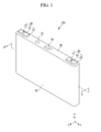
- FIG. 1 is a perspective view of a rechargeable battery according to a first exemplary embodiment of the present invention.
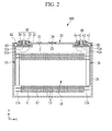
- FIG. 2 is a cross-sectional view taken along line 11-11 in FIG. 1 .
- FIG. 3 is a exploded perspective view of a part of a rechargeable battery according to the first exemplary embodiment of the present invention.
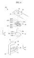
- FIG. 4 is a exploded perspective view of a part of a rechargeable battery according to a modified example of the first exemplary embodiment of the present invention.
- FIG. 5 is a exploded perspective view of a part of a rechargeable battery according to a second exemplary embodiment of the present invention.
- FIG. 6 is a exploded perspective view of a part of a rechargeable battery according to a third exemplary embodiment of the present invention.
- FIG. 7 is a partial cross-sectional view according to a coupling state of the rechargeable battery of FIG. 6 .
- FIG. 8 is a exploded perspective view of a part of a rechargeable battery according to a modified example of the third exemplary embodiment of the present invention.
- FIG. 1 is a perspective view of a rechargeable battery according to a first exemplary embodiment of the present invention and FIG. 2 is a cross-sectional view taken along line II-II of FIG. 1 .
- a rechargeable battery 100 includes a plurality of electrode assemblies 10 formed by winding a first electrode 11 and a second electrode 12 together, having a separator 13 disposed between the first electrode 11 and the second electrode 12, a case 26 in which the electrode assemblies 10 are embedded (or housed), a first terminal part 30 and a second terminal part 40 electrically connected with the electrode assemblies 10, a cap plate 20 coupled with an opening formed in the case 26, and first and second insulating members 60 and 80 installed in the case 26.
- the rechargeable battery 100 is a lithium ion rechargeable battery.
- a squared rechargeable battery will be described by way of example.
- embodiments of the present invention are not limited thereto and the present invention may be applied to a battery such as a lithium polymer battery, or the like.
- first electrode 11 may be a negative electrode and the second electrode 12 may be a positive electrode, or vice versa.
- first electrode 11 and the second electrode 12 will be described instead of the negative electrode and the positive electrode, respectively, but embodiments of the present invention are not limited thereto.
- the electrode assembly 10 is formed by winding the first electrode 11, the second electrode 12, and the separator 13 together to form a jelly roll structure.
- the first electrode 11 and the second electrode 12 each include a current collector formed of a thin metal foil and an active material coated on a surface of the current collector.
- the first electrode 11 and the second electrode 12 may be partitioned into a coated part in which an active material is coated on the current collector and a first electrode non-coated part 11 a and a second electrode non-coated part 12a in which the active material is not coated on the current collector.
- the coated part forms a substantial portion of the first electrode 11 and the second electrode 12 in the electrode assembly 10, and each of the first electrode non-coated part and the second non-coated part 11 a and 12a is disposed at a respective side (e.g., opposite ends) of the coated part in the jelly roll structure.
- the above-described electrode assembly 10 may be formed in a stacked structure, having the separator 13 between the first electrode 11 and the second electrode 12 formed of a plurality of sheets.
- the first electrode non-coated part 11a of the electrode assembly 10 is electrically connected to the first terminal part 30 via a first electrode current collecting member (or current collector) 50
- the second electrode non-coated part 12a is electrically connected to the second terminal part 40 via a second electrode current collecting member (or current collector) 70. Therefore, the first terminal part 30 may include a first electrode terminal, and the second terminal part 40 may include a second electrode terminal.
- the case 26 is formed in an approximately rectangular parallelepiped (or rectangular prism or cuboid) shape, and one surface thereof is provided with an opened opening.
- embodiments of the present invention are not limited thereto, and the case may be formed in various suitable shapes, such as a cylindrical shape, a pouch shape, or the like.
- the cap plate 26 is formed of a thin plate and is coupled with the opening of the case 26 to seal the opening. Further, the cap plate 20 is provided with an electrolyte solution inlet 21 through which the electrolyte solution may be injected into the sealed case 26, wherein the electrolyte solution inlet 21 is sealed by a sealing closure 22 after the electrolyte solution is injected. In addition, the cap plate 20 is provided with a vent hole 23 mounted with a vent plate 24 which is adapted to fracture when an internal pressure of the sealed case 26 exceeds a pressure (e.g., a set pressure).
- a pressure e.g., a set pressure
- the first and second terminal parts 30 and 40 include first and second rivets 31 and 41, first and second terminal plates 32 and 42, a first terminal insulating member 33 disposed between the first and second terminal plates 32 and 42 and the cap plate 20, a conductive connection member 43, and first and second gaskets 34 and 44.
- the first and second rivets 31 and 41 include first and second pillar parts 31 a and 41 a and first and second flange 31 b and 41 b.
- the cap plate 20 may have the polarity of the positive electrode or the negative electrode.
- first and second electrode current collecting members 50 and 70 include first and second electrode coupling parts 52 (see, e.g., FIG. 3 ) coupled with the first and second electrodes 11 and 12, and first and second terminal coupling parts 51 (see, e.g., FIG. 3 ) coupled with the first and second terminal parts 30 and 40.
- the structure of the first and second terminal parts 30 and 40, and the structure of the first and second electrode current collecting members 50 and 70 and first and second insulating members 60 and 80 are substantially the same. Therefore, the description of the second terminal part 40, the second electrode current collecting member 70, and the second insulating member 80 will be omitted.
- the first terminal part 30 may include a cylindrically-shaped terminal rather than a plate-shaped terminal.
- an insulating connection member may be disposed between the cap plate 20 and the second rivet 41. Therefore, in some embodiments of the present invention, the cap plate 20 is not be electrically connected to the second terminal part 40.
- FIG. 3 is a exploded perspective view of a part of a rechargeable battery according to the first exemplary embodiment of the present invention.
- the first rivet 31 includes a pillar part 31 a and a rivet flange 31 b.
- the rivet flange 31 b may include a first rivet flange part 311 b and second and third rivet flange parts 312b and 313b.
- the first rivet flange part 311b may protrude in a direction (z-axis direction) approximately perpendicular to a height direction (y-axis direction) of the pillar part 31 a at one end of the pillar part 31 a.
- the second rivet flange part 312b protrudes in a direction (x-axis direction) approximately perpendicular to a height direction (y-axis direction) of the pillar part 31 a at one end of the first rivet flange part 311 b.
- a third rivet flange part 313b may protrude from the other end of the first rivet flange part 311 b to the side opposite to the second rivet flange part 312b.
- the first gasket 34 may include a body 34a in which a through hole is formed and a gasket flange 34b.
- the gasket flange 34b may include a first gasket flange part 341 b and second and third gasket flange parts 342b and 343b.
- the first gasket flange part 341 b may protrude in a direction (z-axis direction) approximately perpendicular to a height direction (y-axis direction) of the body 34a at one end of the body 34a.
- the second gasket flange part 342b protrudes in a direction (x-axis direction) approximately perpendicular to a height direction (y-axis direction) of the body 34a at one end of the first gasket flange part 341 b.
- the third gasket flange part 343b protrudes from the other end of the first gasket flange part 341 b (e.g., positioned opposite to the second gasket flange part 342b).
- a first insulating member 60 includes a coupling groove 61, a plurality of fixing protrusions 62 fixed to a plurality of grooves 25 or cavities or holes formed in the cap plate 20, and a through hole 63 through which the first rivet 31 penetrates.
- the coupling groove 61 may be formed on one surface of the first insulating member 60 opposite to (e.g., facing) the electrode assembly 10, as shown in FIG. 2 .
- the first electrode current collecting member 50 may include a first electrode coupling part 52 and a first terminal coupling part 51 that are coupled with the first electrode 11.
- the fixing protrusions 62 may be fixed to the grooves 25 formed in the cap plate 20.
- first gasket 34 may be inserted into the coupling groove 61 formed on the bottom of the first insulating member 60.
- the body 34a of the gasket 34 is inserted into the through hole 63 and the coupling groove 61 may receive the first gasket flange part 341 b and the second gasket flange part 342b formed in the first gasket 34.
- the second gasket flange part 342b of the first gasket 34 may be disposed in parallel with the length direction (x-axis direction) of the cap plate 20.
- the pillar part 31 a of the first rivet 31 may be disposed to penetrate through the body 34a of the first gasket 34, the through hole 63 of the first insulating member 60, and the terminal hole 26 formed on the cap plate 20, and the first rivet flange part 311 b, the second rivet flange part 312b, and the third rivet flange part 313b may be received in the coupling groove 61.
- the second rivet flange part 312b and the third rivet flange part 313b are closely disposed to the second gasket flange part 342b and the third gasket flange part 343b, respectively, so as to be disposed in the coupling groove 61.
- the first rivet flange part 311 b of the first rivet 31, the first gasket flange part 341 b of the first gasket 34, the second and third rivet flange parts 312b and 313b of the first rivet, and the second and third gasket flange parts 342b and 343b of the first gasket 34 may be closely disposed to each other in the coupling groove 61.
- the size of the first gasket flange part 341 b may be greater than or equal to the size of the first rivet flange part 311 b
- the size of the second gasket flange part 342b may be greater than or equal to the size of the second rivet flange part 312b
- the size of the third gasket flange part 343b may be greater than or equal to the size of the third rivet flange part 313b.
- the size of the gasket flange 34b of the first gasket 34 may be greater than or equal to the size of the rivet flange 31 b of the first rivet 31.
- the end of the pillar part 31a of the first rivet 31 may be coupled with the first terminal plate 32 by the rivet, and the first terminal coupling part 51 of the first electrode current collecting member 50 may be inserted into the coupling groove 61 to be coupled with the first rivet 31 by a weld, or the like.
- the first insulating member 60 is disposed between the electrode current collector 10 and the cap plate 20 by fixing the rivet flange 31 b of the first rivet 31 to the coupling groove 61.
- the electrolyte solution injected into the case of the rechargeable battery 100 may permeate into the coupling groove 61 of the first insulating member 60 or between the first insulating member 60 and the cap plate 20, such that an electrical short is formed between the cap plate 20 and the first rivet 31.
- the size of the gasket flange 34b according to the exemplary embodiment may be greater than or equal to the size of the rivet flange 31 b, the adhesion between the gasket flange 34b and the rivet flange 31 b may be more improved compared to a comparative example in which the size of the gasket flange 34b is smaller than the size of the rivet flange 31 b.
- the electrolyte solution permeating into the first insulating member 60 passes between the second gasket flange part 342b and the first insulating member 60 so as to reach the cap plate 20.
- the adhesion between the rivet flange 31 b and the first gasket 34 is improved by the gasket flange 34b of the first gasket 34 according to the exemplary embodiment, and the length of the entire path through which the electrolyte needs to permeate into the first insulating member 60 to reach the cap plate 20 is increased, such that the risk of an electrical short between the cap plate 20 and the first rivet 31 due to the electrolyte solution can be reduced.
- FIG. 4 is a partially exploded perspective view of a rechargeable battery according to another embodiment of the present invention.
- the rechargeable battery 101 according to the exemplary embodiment of FIG. 4 has the same structure as the rechargeable battery 100 according to the first exemplary embodiment, except for the first gasket 34', and therefore, a description of the same structure will be omitted.
- the first gasket 34' may include a body 34'a in which a through hole is formed and a gasket flange part 34'b.
- the gasket flange part 34'b may include a first gasket flange part 341'b, a second gasket flange part 342'b, and a third gasket flange part 343'b.
- the first gasket flange part 341'b may protrude in a direction (z-axis direction) approximately perpendicular to a height direction (y-axis direction) of the body 34'a at one end of the body 34'a.
- the second gasket flange part 342'b may protrude in a direction (x-axis direction) approximately perpendicular to a height direction (y-axis direction) of the body 34'a at one end of the first gasket flange part 341'b and the third gasket flange part 343'b may protrude from the other end of the first gasket flange 341'b and may be positioned at an opposite side of the one end thereof.
- the end of the second gasket flange part 342'b may be bent downwardly to form a bent portion 342'b1 of the second gasket flange part 342'b.
- the end of the third gasket flange part 343'b may be bent downwardly to form a bent portion 343'b1.
- the second and third gasket flange parts 342'b and 343'b may also be closely disposed at the side of the second rivet flange part 312b and the third rivet flange part 313b, respectively.
- the entire path through which the electrolyte solution permeates into the first insulating member 60 to reach the cap plate 20 is increased, the risk of an electrical short between the cap plate 20 and the first rivet 31 due to the electrolyte solution can be reduced.
- FIG. 5 is a exploded perspective view of a part of a rechargeable battery according to a second exemplary embodiment of the present invention.
- the rechargeable battery 200 according to the second exemplary embodiment has substantially the same structure as the rechargeable battery 100 according to the first exemplary embodiment, except for the first gasket 34", and therefore, the description of structures that are substantially the same will be omitted.
- a first gasket 34" includes a body 34"a in which a through hole is formed, a gasket flange part 34"b, and a rivet flange coupling lip 34"c.
- the gasket flange part 34"b includes a first gasket flange part 341"b, a second gasket flange part 342"b, and a third gasket flange part 343"b.
- first gasket flange part 341"b, the second gasket flange part 342"b, and the third gasket flange part 343"b according to the exemplary embodiment have substantially the same structure as the first gasket flange part 341 b and the second gasket flange part 342b of the first gasket 34 according to the first exemplary embodiment and therefore, the descriptions of the substantially similar structures will be omitted.
- a rivet flange coupling lip 34"c is disposed on the bottom (e.g., in a direction facing toward the first and second rivet flange parts 31 b of rivet (31) of the gasket flange 34"b.
- the rivet flange coupling lip 34"c includes a first rivet flange part coupling lip 341"c formed on the bottom of the first gasket flange part 341"b, a second rivet flange part coupling lip 342"c formed on the bottom of the second gasket flange part 342"b, and a third rivet flange part coupling lip 343"c formed on the bottom of the third gasket flange part 343"b.
- the first rivet flange part 311 b is coupled with the first rivet flange part coupling lip 341 "c
- the second rivet flange part 312b is coupled with the second rivet flange part coupling lip 342"c
- the third rivet flange part 313b is coupled with the third rivet flange part coupling lip 343"c.
- the rivet flange 31 b is inserted into the rivet flange coupling lip 34"c, such that the sides of the rivet flange 31 b are also closely disposed to the gasket flange part 34"b.
- the adhesion between the gasket flange 34"b and the rivet flange 31 b may be more improved.
- the risk of an electrical short between the cap plate 20 and the first rivet 31 due to the electrolyte solution may be reduced.
- FIG. 6 is a exploded perspective view of a part of a rechargeable battery according to a third exemplary embodiment and FIG. 7 is a partial cross-sectional view according to a coupling state of the rechargeable battery of FIG. 6 .
- a rechargeable battery 300 according to the exemplary embodiment has substantially the same structure as the rechargeable battery 200 according to the second exemplary embodiment, except for a first insulating member 90, and therefore, the description of the substantially similar structures will be omitted.
- the first insulating member 90 includes a coupling groove 91 with which the first electrode current collecting member (or current collector) 50 is coupled and a plurality of fixing protrusions 92 fixed to the plurality of grooves 25 formed in the cap plate 20.
- the coupling groove 91 is formed in a surface of the first insulating member 90 that is opposite to (e.g., facing) the cap plate 20.
- the first electrode coupling part 52 of the first electrode current collecting member 50 is received in the coupling groove 91 formed in the first insulating member 90.
- first rivet 31 and the first gasket 34" are sequentially stacked in the coupling groove 91.
- the first insulating member 90 may prevent or mitigate the contact between the first electrode coupling part 52 and the electrolyte solution. Therefore, it is possible to prevent or reduce the risk of an electrical short between the cap plate 20 and the first rivet 31.
- FIG. 8 is a exploded perspective view of a part of a rechargeable battery according to a modified example of a third exemplary embodiment.
- a rechargeable battery 301 according to the modified third exemplary embodiment has substantially the same structure as the rechargeable battery 300 according to the third exemplary embodiment, except for a first electrode current collecting member coupling ring 93 of the first insulating member 90 and therefore, the description of substantially similar structures will be omitted.
- the first insulating member 90 includes a first electrode current collecting member coupling ring 93 that extends from one side of the first insulating member 90.
- one side of the first electrode current collecting member 50 is fixed by the first electrode current collecting member coupling ring 93.
- the first electrode current collecting member 50 may be more stably coupled with the first insulating member 90 by the first electrode current collecting member coupling ring 93.
- the first, second, and third rivet flange parts and first, second, and third gasket flange parts have substantially rectangular shapes.
- embodiments of the present invention are not limited thereto.
- the first, second, and third rivet flange parts may be circular, oval, or triangular in shape and the first, second, and third gasket flange parts may have corresponding shapes.
- Rivet flange 311b First rivet flange part
- Second rivet flange part 34a Body
- 343b, 343'b, 343"b Third gasket flange part
Abstract
Description
- Embodiments of the present invention generally relate to a rechargeable battery, and more particularly, to a rechargeable battery having an improved gasket and terminal structure.
- A rechargeable battery is a battery that can be recharged, unlike a primary battery that cannot be recharged. A low-capacity rechargeable battery may be used for small portable electronic devices such as a mobile phone, a notebook computer, and a camcorder and a large-capacity battery may be used as a power supply for driving a motor such as a hybrid or electric car or a large-capacity power storage device.
- Recently, a high-output rechargeable battery using a non-aqueous electrolyte solution having high energy density has been developed. The high-output rechargeable battery is configured of a large-capacity battery module in which a plurality of rechargeable batteries are connected to each other in series so as to be used to motors for devices requiring large power, for example, an electric car, a hybrid car, or the like.
- The rechargeable battery may be configured to have a cylindrical shape, a square shape, or the like.
- However, in some circumstances, the electrolyte solution in a case of the rechargeable battery infiltrates between an electrode terminal and a cap plate, thereby causing an electrical short between the electrode terminal and the cap plate.
- In addition, the electrolyte solution in the case of the rechargeable battery may leak outside of the case.
- The above information disclosed in this Background section is only for enhancement of understanding of the background of the described technology and therefore it may contain information that does not form the prior art that is already known in this country to a person of ordinary skill in the art.
- Aspects of embodiments of the present invention are directed toward a rechargeable battery capable of preventing or reducing the likelihood of an electrical short between an electrode terminal and a cap plate by blocking an electrolyte solution in a case of the rechargeable battery from infiltrating between the electrode terminal and the cap plate.
- In addition, aspects of embodiments of the present invention are directed toward a rechargeable battery capable of preventing or protecting an electrolyte solution from being leaked to the outside of a case.
According to an embodiment of the present invention, the rechargeable battery includes an electrode assembly in a case; a cap plate coupled to an opening of the case; and a rivet electrically connected to the electrode assembly, wherein the rivet comprises a rivet flange;
and further including a gasket between the rivet flange and the cap plate, wherein the gasket comprises a gasket body and connected to the gasket body a gasket flange coupled with the rivet flange in a contacting area Ac; wherein a through hole extends through the gasket,
wherein the rivet flange comprises a first rivet flange part and a second rivet flange part, and the gasket flange comprises a first gasket flange part configured to be coupled with the first rivet flange part; and a second gasket flange part configured to be coupled with the second rivet flange part.
Preferably, the first gasket flange part projects in a direction perpendicular to the longitudinal axis of the through hole of the gasket body, and the second gasket flange part projects in a direction perpendicular to the longitudinal axis of the through hole of the gasket body as well as perpendicular to the direction of the first gasket flange part.
The contacting area Ac and the cross-sectional area of the through hole Ath should meet the condition Ac ≥ 3*Ath, in particular Ac ≥ 5*Ath, and in a preferredembodiment Act 10*Ath.
In a preferred embodiment, the rivet comprises a pillar part, wherein the rivet flange is provided on one end of the pillar part, wherein the pillar part extends through the through hole of the gasket and through the cap plate, and the cross-sectional area of the gasket flange Agf and the cross-sectional area of the rivet flange Arf meet the condition Agf ≥ Arf, in particular
In the present invention, the cross-sectional area of the gasket flange Agf is defined as the cross-sectional area of the gasket less cross-sectional area of the gasket body; and the cross-sectional area of the rivet flange Arf is defined as the cross-sectional area of the rivet less cross-sectional area of the rivet pillar part;
The cross-sectional area of the gasket body Agb and the cross-sectional area of the through hole Ath of the gasket may meet the condition Ath ≥1,2* Agb, in particular Ath ≥1,2 to 1,6* Agb; and in a preferred embodiment Ath >2* Agb.
The surface of the rivet flange facing the gasket flange may be stepped, and the surface of the gasket flange facing the rivet flange may be stepped complementary.
In a further preferred embodiment, the first rivet flange part projects in a first direction perpendicular to the longitudinal axis of the pillar part; and the second rivet flange part projects in a second direction perpendicular to the longitudinal axis of the pillar part as well as perpendicular to the direction of the first rivet flange part; wherein the contacting area includes the areas in which the first rivet flange part contacts the first gasket flange part and in which the second rivet flange part contacts the second gasket flange part. Preferably, the cross-sectional area of the first gasket flange part is bigger than the cross-sectional area of the first rivet flange part, and/or the cross-sectional area of the second gasket flange part is bigger than the cross-sectional area of the second rivet flange part.
Further, the rivet flange may comprise a third rivet flange part, and the gasket flange may comprise a third gasket flange part, wherein the contacting area includes the areas in which the first rivet flange part contacts the first gasket flange part; in which the second rivet flange part contacts the second gasket flange part and in which the third rivet flange part contacts the third gasket flange part.
In that case, the third rivet flange part extends in the second direction opposite to the second rivet flange part, and/or the third gasket flange part extends in the second direction opposite to the second gasket flange part.
Preferably, the cross-sectional area of the third gasket flange part is bigger than the cross-sectional area of the third rivet flange part.
In a further preferred embodiment, the rechargeable battery further comprises an insulating member having a through hole, wherein the gasket body extends through the through hole of the insulating member.
The gasket flange may comprise a bent portion extending in a third direction perpendicular to the first and second direction, wherein the bent portion covers at least a part of a brim of the rivet flange.
Further, the rechargeable battery includes a current collector, wherein the rivet is electrically coupled to the electrode assembly via the current collector, wherein the current collector comprises a terminal coupling part and an electrode coupling part.
Preferably, the insulating member includes a cavity in which the gasket, the rivet flange as well as the terminal coupling part is positioned.
The insulating member may further include a coupling ring at a side of the insulating member, wherein the coupling ring embraces a portion of the electrode coupling part.
Preferably, at least one of the battery parts insulating member and cap plate includes at least one cavity or hole and the respective other part includes at least one fixing protrusion coupled with the cavity or hole. - That is, according to an embodiment of the present invention, the rechargeable battery includes: an electrode assembly in a case; a cap plate coupled to an opening of the case; a rivet electrically connected to the electrode assembly, the rivet including: a first rivet flange part; and a second rivet flange part; and a gasket between the rivet flange and the cap plate, the gasket including: a first gasket flange part configured to be coupled with the first rivet flange part; and a second gasket flange part configured to be coupled with the second rivet flange part.
- The first gasket flange part may be greater than or equal to the first rivet flange part in size.
- The second gasket flange part may be greater than or equal to the second rivet flange part in size.
- The rivet may further include a pillar part extending through the cap plate.
- The gasket may have a through hole and the pillar part of the rivet may extend through the through hole of the gasket.
- The first rivet flange part may extend in a first direction and a second direction perpendicular to the first direction, the second rivet flange part may extend in the second direction, the second rivet flange part may extend from a side edge of the first rivet flange part, the first gasket flange part may extend in the first direction and the second direction, the second gasket flange part may extend in the second direction, and the second gasket flange part may extend from a side edge of the first gasket, the gasket may include a gasket body extending in a third direction perpendicular to the first and second directions, and the through hole of the gasket may be formed through the gasket body in the third direction.
- The rechargeable battery may further include an insulating member having a through hole, and the gasket body may extend through the through hole of the insulating member.
- The first rivet flange part may extend in a first direction and a second direction perpendicular to the first direction, the second rivet flange part may extend in the second direction, the second rivet flange part may extend from a side edge of the first rivet flange part, the first gasket flange part may extend in the first direction and the second direction, the second gasket flange part may extend in the second direction, and the second gasket flange part may extend from a side edge of the first gasket.
- The second gasket flange part may include a bent portion extending in a third direction perpendicular to the first and second directions and covering an end of the second rivet flange part.
- The rivet may further include: a third rivet flange part extending in the second direction, the third rivet flange part extending from another side edge of the first rivet flange part facing oppositely away from the side edge from which the second rivet flange part extends.
- The gasket may further include: a third gasket flange part extending in the second direction, the third gasket flange part extending from another side edge of the first gasket flange part facing oppositely away from the side edge from which the second gasket flange part extends and configured to be coupled with the third rivet flange part.
- The third gasket flange part may be greater than or equal to the third rivet flange part in size.
- The third gasket flange part may include a bent portion extending in a third direction perpendicular to the first and second directions and covering an end of the third rivet flange part.
- The gasket may further include a rivet flange coupling part including: a first rivet flange part coupling lip extending from the first gasket flange part in a third direction perpendicular to the first and second directions; and a second rivet flange part coupling lip extending from the second gasket flange part in the third direction.
- The second gasket flange part may be thinner than the first gasket flange part.
- The rechargeable battery may further include an insulating member having a coupling groove configured to house the rivet flange and the gasket, wherein the insulating member may be between the gasket and the cap plate, and the gasket and the first and second rivet flange parts are between the cap plate and the insulating member.
- The rechargeable battery may further include a current collector, wherein the rivet may be electrically coupled to the electrode assembly via the current collector, the current collector comprising a terminal coupling part and an electrode coupling part.
- The insulating member may include a coupling groove configured to house the terminal coupling part between the coupling groove and the rivet flange.
- The insulating member may further include a coupling ring at a side edge of the insulating member, the coupling ring encircling a portion of the electrode coupling part.
- The cap plate may include a plurality of grooves, preferably in form of cavities or holes, and the insulating member may include fixing protrusions configured to be respectively coupled with the grooves.
-
FIG. 1 is a perspective view of a rechargeable battery according to a first exemplary embodiment of the present invention. -
FIG. 2 is a cross-sectional view taken along line 11-11 inFIG. 1 . -
FIG. 3 is a exploded perspective view of a part of a rechargeable battery according to the first exemplary embodiment of the present invention. -
FIG. 4 is a exploded perspective view of a part of a rechargeable battery according to a modified example of the first exemplary embodiment of the present invention. -
FIG. 5 is a exploded perspective view of a part of a rechargeable battery according to a second exemplary embodiment of the present invention. -
FIG. 6 is a exploded perspective view of a part of a rechargeable battery according to a third exemplary embodiment of the present invention. -
FIG. 7 is a partial cross-sectional view according to a coupling state of the rechargeable battery ofFIG. 6 . -
FIG. 8 is a exploded perspective view of a part of a rechargeable battery according to a modified example of the third exemplary embodiment of the present invention. - Embodiments of the present invention will be described more fully hereinafter with reference to the accompanying drawings, in which exemplary embodiments of the invention are shown. As those skilled in the art would realize, the described embodiments may be modified in various different ways, all without departing from the spirit or scope of the present invention.
- In the drawings, dimensions of layers, regions, etc., are exaggerated for clarity. It will be understood that when one layer or one element is considered to as being "on" another element, it can be directly on the other element or intervening elements may also be present therebetween. Further, it will be understood that when one layer or one element is considered to as being "under" another element, it can be directly on (under) the other element or at least one intervening element may also be present therebetween. In addition, it will be understood that when one layer is considered to as being "between" two layers, it can be a unique layer between two layers or at least one other layer may also be present therebetween. Like reference numerals designate like elements throughout the specification and the drawings.
-
FIG. 1 is a perspective view of a rechargeable battery according to a first exemplary embodiment of the present invention andFIG. 2 is a cross-sectional view taken along line II-II ofFIG. 1 . - Referring to
FIGS. 1 and2 , arechargeable battery 100 according to an exemplary embodiment of the present invention includes a plurality ofelectrode assemblies 10 formed by winding afirst electrode 11 and asecond electrode 12 together, having aseparator 13 disposed between thefirst electrode 11 and thesecond electrode 12, acase 26 in which theelectrode assemblies 10 are embedded (or housed), a firstterminal part 30 and a secondterminal part 40 electrically connected with theelectrode assemblies 10, acap plate 20 coupled with an opening formed in thecase 26, and first and second insulatingmembers case 26. - The
rechargeable battery 100 according to one exemplary embodiment is a lithium ion rechargeable battery. Herein, a squared rechargeable battery will be described by way of example. However, embodiments of the present invention are not limited thereto and the present invention may be applied to a battery such as a lithium polymer battery, or the like. - In addition, the
first electrode 11 may be a negative electrode and thesecond electrode 12 may be a positive electrode, or vice versa. However, for the sake of convenience, in the exemplary embodiment, thefirst electrode 11 and thesecond electrode 12 will be described instead of the negative electrode and the positive electrode, respectively, but embodiments of the present invention are not limited thereto. - The
electrode assembly 10 is formed by winding thefirst electrode 11, thesecond electrode 12, and theseparator 13 together to form a jelly roll structure. Thefirst electrode 11 and thesecond electrode 12 each include a current collector formed of a thin metal foil and an active material coated on a surface of the current collector. In addition, thefirst electrode 11 and thesecond electrode 12 may be partitioned into a coated part in which an active material is coated on the current collector and a first electrodenon-coated part 11 a and a second electrodenon-coated part 12a in which the active material is not coated on the current collector. The coated part forms a substantial portion of thefirst electrode 11 and thesecond electrode 12 in theelectrode assembly 10, and each of the first electrode non-coated part and the secondnon-coated part - However, embodiments of the present invention are not limited thereto. The above-described
electrode assembly 10 may be formed in a stacked structure, having theseparator 13 between thefirst electrode 11 and thesecond electrode 12 formed of a plurality of sheets. - The first electrode
non-coated part 11a of theelectrode assembly 10 is electrically connected to the firstterminal part 30 via a first electrode current collecting member (or current collector) 50, and the second electrodenon-coated part 12a is electrically connected to the secondterminal part 40 via a second electrode current collecting member (or current collector) 70. Therefore, the firstterminal part 30 may include a first electrode terminal, and the secondterminal part 40 may include a second electrode terminal. - The
case 26 is formed in an approximately rectangular parallelepiped (or rectangular prism or cuboid) shape, and one surface thereof is provided with an opened opening. - However, embodiments of the present invention are not limited thereto, and the case may be formed in various suitable shapes, such as a cylindrical shape, a pouch shape, or the like.
- According to one embodiment of the present invention, the
cap plate 26 is formed of a thin plate and is coupled with the opening of thecase 26 to seal the opening. Further, thecap plate 20 is provided with anelectrolyte solution inlet 21 through which the electrolyte solution may be injected into the sealedcase 26, wherein theelectrolyte solution inlet 21 is sealed by a sealingclosure 22 after the electrolyte solution is injected. In addition, thecap plate 20 is provided with avent hole 23 mounted with avent plate 24 which is adapted to fracture when an internal pressure of the sealedcase 26 exceeds a pressure (e.g., a set pressure). - The first and second
terminal parts second rivets terminal plates member 33 disposed between the first and secondterminal plates cap plate 20, aconductive connection member 43, and first andsecond gaskets second rivets second pillar parts second flange - According to one exemplary embodiment of the present invention, because the
cap plate 20 is electrically connected to the secondterminal part 40 by theconductive connection member 43, thecap plate 20 may have the polarity of the positive electrode or the negative electrode. - Further, the first and second electrode
current collecting members FIG. 3 ) coupled with the first andsecond electrodes FIG. 3 ) coupled with the first and secondterminal parts - In this configuration, according to one exemplary embodiment of the present invention, the structure of the first and second
terminal parts current collecting members members terminal part 40, the second electrodecurrent collecting member 70, and the second insulatingmember 80 will be omitted. - However, the first
terminal part 30 according to one exemplary embodiment of the present invention may include a cylindrically-shaped terminal rather than a plate-shaped terminal. - Instead of the
conductive connection member 43, an insulating connection member may be disposed between thecap plate 20 and thesecond rivet 41. Therefore, in some embodiments of the present invention, thecap plate 20 is not be electrically connected to the secondterminal part 40. -
FIG. 3 is a exploded perspective view of a part of a rechargeable battery according to the first exemplary embodiment of the present invention. - Referring to
FIG. 3 , according to one exemplary embodiment of the present invention, thefirst rivet 31 includes apillar part 31 a and arivet flange 31 b. - In more detail, the
rivet flange 31 b may include a firstrivet flange part 311 b and second and thirdrivet flange parts rivet flange part 311b may protrude in a direction (z-axis direction) approximately perpendicular to a height direction (y-axis direction) of thepillar part 31 a at one end of thepillar part 31 a. Further, the secondrivet flange part 312b protrudes in a direction (x-axis direction) approximately perpendicular to a height direction (y-axis direction) of thepillar part 31 a at one end of the firstrivet flange part 311 b. A thirdrivet flange part 313b may protrude from the other end of the firstrivet flange part 311 b to the side opposite to the secondrivet flange part 312b. - In addition, the
first gasket 34 according to the exemplary embodiment may include abody 34a in which a through hole is formed and agasket flange 34b. - In more detail, the
gasket flange 34b may include a firstgasket flange part 341 b and second and thirdgasket flange parts gasket flange part 341 b may protrude in a direction (z-axis direction) approximately perpendicular to a height direction (y-axis direction) of thebody 34a at one end of thebody 34a. Further, the secondgasket flange part 342b protrudes in a direction (x-axis direction) approximately perpendicular to a height direction (y-axis direction) of thebody 34a at one end of the firstgasket flange part 341 b. The thirdgasket flange part 343b protrudes from the other end of the firstgasket flange part 341 b (e.g., positioned opposite to the secondgasket flange part 342b). - In addition, a first insulating
member 60 according to one embodiment of the present invention includes acoupling groove 61, a plurality of fixingprotrusions 62 fixed to a plurality ofgrooves 25 or cavities or holes formed in thecap plate 20, and a throughhole 63 through which thefirst rivet 31 penetrates. In this configuration, thecoupling groove 61 may be formed on one surface of the first insulatingmember 60 opposite to (e.g., facing) theelectrode assembly 10, as shown inFIG. 2 . - Moreover, the first electrode
current collecting member 50 may include a firstelectrode coupling part 52 and a firstterminal coupling part 51 that are coupled with thefirst electrode 11. - Hereinafter, the coupling relationship between the
first rivet 31 and thefirst gasket 34 according to the exemplary embodiment will be described in more detail. - In the first insulating
member 60, the fixingprotrusions 62 may be fixed to thegrooves 25 formed in thecap plate 20. - Further, the
first gasket 34 may be inserted into thecoupling groove 61 formed on the bottom of the first insulatingmember 60. In this configuration, thebody 34a of thegasket 34 is inserted into the throughhole 63 and thecoupling groove 61 may receive the firstgasket flange part 341 b and the secondgasket flange part 342b formed in thefirst gasket 34. - In this case, the second
gasket flange part 342b of thefirst gasket 34 may be disposed in parallel with the length direction (x-axis direction) of thecap plate 20. - In addition, the
pillar part 31 a of thefirst rivet 31 may be disposed to penetrate through thebody 34a of thefirst gasket 34, the throughhole 63 of the first insulatingmember 60, and theterminal hole 26 formed on thecap plate 20, and the firstrivet flange part 311 b, the secondrivet flange part 312b, and the thirdrivet flange part 313b may be received in thecoupling groove 61. In this case, the secondrivet flange part 312b and the thirdrivet flange part 313b are closely disposed to the secondgasket flange part 342b and the thirdgasket flange part 343b, respectively, so as to be disposed in thecoupling groove 61. - Therefore, the first
rivet flange part 311 b of thefirst rivet 31, the firstgasket flange part 341 b of thefirst gasket 34, the second and thirdrivet flange parts gasket flange parts first gasket 34 may be closely disposed to each other in thecoupling groove 61. - In this configuration, the size of the first
gasket flange part 341 b may be greater than or equal to the size of the firstrivet flange part 311 b, the size of the secondgasket flange part 342b may be greater than or equal to the size of the secondrivet flange part 312b, and the size of the thirdgasket flange part 343b may be greater than or equal to the size of the thirdrivet flange part 313b. - Consequently, the size of the
gasket flange 34b of thefirst gasket 34 may be greater than or equal to the size of therivet flange 31 b of thefirst rivet 31. - Referring again to
FIG. 2 , the end of thepillar part 31a of thefirst rivet 31 may be coupled with the firstterminal plate 32 by the rivet, and the firstterminal coupling part 51 of the first electrodecurrent collecting member 50 may be inserted into thecoupling groove 61 to be coupled with thefirst rivet 31 by a weld, or the like. - Therefore, in one embodiment of the present invention, the first insulating
member 60 is disposed between the electrodecurrent collector 10 and thecap plate 20 by fixing therivet flange 31 b of thefirst rivet 31 to thecoupling groove 61. - The electrolyte solution injected into the case of the
rechargeable battery 100 according to one exemplary embodiment may permeate into thecoupling groove 61 of the first insulatingmember 60 or between the first insulatingmember 60 and thecap plate 20, such that an electrical short is formed between thecap plate 20 and thefirst rivet 31. In this case, since the size of thegasket flange 34b according to the exemplary embodiment may be greater than or equal to the size of therivet flange 31 b, the adhesion between thegasket flange 34b and therivet flange 31 b may be more improved compared to a comparative example in which the size of thegasket flange 34b is smaller than the size of therivet flange 31 b. - Therefore, it is possible to prevent or reduce the risk of the electrolyte solution in the
case 26 from leaking outside of thecase 26. - In addition, because the second
gasket flange part 342b extending from one end of the firstgasket flange part 341 b is disposed close to the secondrivet flange part 312b and because the thirdgasket flange part 343b extending from an opposite end of the firstgasket flange part 341 b is disposed close to the thirdrivet flange part 313b, the electrolyte solution permeating into the first insulatingmember 60 passes between the secondgasket flange part 342b and the first insulatingmember 60 so as to reach thecap plate 20. - Therefore, the adhesion between the
rivet flange 31 b and thefirst gasket 34 is improved by thegasket flange 34b of thefirst gasket 34 according to the exemplary embodiment, and the length of the entire path through which the electrolyte needs to permeate into the first insulatingmember 60 to reach thecap plate 20 is increased, such that the risk of an electrical short between thecap plate 20 and thefirst rivet 31 due to the electrolyte solution can be reduced. -
FIG. 4 is a partially exploded perspective view of a rechargeable battery according to another embodiment of the present invention. - In this case, the
rechargeable battery 101 according to the exemplary embodiment ofFIG. 4 has the same structure as therechargeable battery 100 according to the first exemplary embodiment, except for the first gasket 34', and therefore, a description of the same structure will be omitted. - Referring to
FIG. 4 , the first gasket 34' according to the exemplary embodiment may include a body 34'a in which a through hole is formed and a gasket flange part 34'b. - In more detail, the gasket flange part 34'b may include a first gasket flange part 341'b, a second gasket flange part 342'b, and a third gasket flange part 343'b.
- In this configuration, the first gasket flange part 341'b may protrude in a direction (z-axis direction) approximately perpendicular to a height direction (y-axis direction) of the body 34'a at one end of the body 34'a.
- Further, the second gasket flange part 342'b may protrude in a direction (x-axis direction) approximately perpendicular to a height direction (y-axis direction) of the body 34'a at one end of the first gasket flange part 341'b and the third gasket flange part 343'b may protrude from the other end of the first gasket flange 341'b and may be positioned at an opposite side of the one end thereof.
- In this configuration, the end of the second gasket flange part 342'b may be bent downwardly to form a bent portion 342'b1 of the second gasket flange part 342'b. Similarly, the end of the third gasket flange part 343'b may be bent downwardly to form a bent portion 343'b1.
- Therefore, the second and third gasket flange parts 342'b and 343'b may also be closely disposed at the side of the second
rivet flange part 312b and the thirdrivet flange part 313b, respectively. - As a result, it is possible to further improve the adhesion between the
rivet flange 31 b and the first gasket 34' by bent portions 342'b1 and 343'b1 of the second and third gasket flange parts 342'b and 343'b according to the exemplary embodiment. Therefore, it is possible to prevent or protect the electrolyte solution in thecase 26 from being leaked to the outside of thecase 26. - In addition, according to one exemplary embodiment, because the entire path through which the electrolyte solution permeates into the first insulating
member 60 to reach thecap plate 20 is increased, the risk of an electrical short between thecap plate 20 and thefirst rivet 31 due to the electrolyte solution can be reduced. -
FIG. 5 is a exploded perspective view of a part of a rechargeable battery according to a second exemplary embodiment of the present invention. - The
rechargeable battery 200 according to the second exemplary embodiment has substantially the same structure as therechargeable battery 100 according to the first exemplary embodiment, except for thefirst gasket 34", and therefore, the description of structures that are substantially the same will be omitted. - Referring to
FIG. 5 , afirst gasket 34" according to the exemplary embodiment includes abody 34"a in which a through hole is formed, agasket flange part 34"b, and a rivetflange coupling lip 34"c. - According to the exemplary embodiment, the
gasket flange part 34"b includes a firstgasket flange part 341"b, a secondgasket flange part 342"b, and a thirdgasket flange part 343"b. - However, the first
gasket flange part 341"b, the secondgasket flange part 342"b, and the thirdgasket flange part 343"b according to the exemplary embodiment have substantially the same structure as the firstgasket flange part 341 b and the secondgasket flange part 342b of thefirst gasket 34 according to the first exemplary embodiment and therefore, the descriptions of the substantially similar structures will be omitted. - Further, a rivet
flange coupling lip 34"c according to the exemplary embodiment is disposed on the bottom (e.g., in a direction facing toward the first and secondrivet flange parts 31 b of rivet (31) of thegasket flange 34"b. - In more detail, the rivet
flange coupling lip 34"c includes a first rivet flangepart coupling lip 341"c formed on the bottom of the firstgasket flange part 341"b, a second rivet flangepart coupling lip 342"c formed on the bottom of the secondgasket flange part 342"b, and a third rivet flangepart coupling lip 343"c formed on the bottom of the thirdgasket flange part 343"b. - Therefore, the first
rivet flange part 311 b is coupled with the first rivet flangepart coupling lip 341 "c, the secondrivet flange part 312b is coupled with the second rivet flangepart coupling lip 342"c, and the thirdrivet flange part 313b is coupled with the third rivet flangepart coupling lip 343"c. - Therefore, according to the exemplary embodiment, the
rivet flange 31 b is inserted into the rivetflange coupling lip 34"c, such that the sides of therivet flange 31 b are also closely disposed to thegasket flange part 34"b. - Therefore, the adhesion between the
gasket flange 34"b and therivet flange 31 b may be more improved. - As a result, it is possible to prevent or reduce the risk of the electrolyte solution in the
case 26 from being leaked outside of thecase 26. - In addition, because the entire path through which the electrolyte solution must permeate into the first insulating
member 60 to reach thecap plate 20 is increased, the risk of an electrical short between thecap plate 20 and thefirst rivet 31 due to the electrolyte solution may be reduced. -
FIG. 6 is a exploded perspective view of a part of a rechargeable battery according to a third exemplary embodiment andFIG. 7 is a partial cross-sectional view according to a coupling state of the rechargeable battery ofFIG. 6 . - In this embodiment, a
rechargeable battery 300 according to the exemplary embodiment has substantially the same structure as therechargeable battery 200 according to the second exemplary embodiment, except for a first insulatingmember 90, and therefore, the description of the substantially similar structures will be omitted. - Referring to
FIGS. 6 and7 , the first insulatingmember 90 according to the third exemplary embodiment includes acoupling groove 91 with which the first electrode current collecting member (or current collector) 50 is coupled and a plurality of fixingprotrusions 92 fixed to the plurality ofgrooves 25 formed in thecap plate 20. - In this configuration, the
coupling groove 91 according to the third exemplary embodiment is formed in a surface of the first insulatingmember 90 that is opposite to (e.g., facing) thecap plate 20. - Therefore, as shown in
FIG. 7 , the firstelectrode coupling part 52 of the first electrodecurrent collecting member 50 is received in thecoupling groove 91 formed in the first insulatingmember 90. - In addition, the
first rivet 31 and thefirst gasket 34" are sequentially stacked in thecoupling groove 91. - Therefore, it is possible to more easily couple the first electrode
current collecting member 50, thefirst rivet 31, and thefirst gasket 34". - Moreover, because the first
electrode coupling part 52 of the first electrodecurrent collecting member 50 is received in thecoupling groove 91, the first insulatingmember 90 according to the third exemplary embodiment may prevent or mitigate the contact between the firstelectrode coupling part 52 and the electrolyte solution. Therefore, it is possible to prevent or reduce the risk of an electrical short between thecap plate 20 and thefirst rivet 31. -
FIG. 8 is a exploded perspective view of a part of a rechargeable battery according to a modified example of a third exemplary embodiment. - In this case, a
rechargeable battery 301 according to the modified third exemplary embodiment has substantially the same structure as therechargeable battery 300 according to the third exemplary embodiment, except for a first electrode current collectingmember coupling ring 93 of the first insulatingmember 90 and therefore, the description of substantially similar structures will be omitted. - Referring to
FIG. 8 , the first insulatingmember 90 according to the exemplary embodiment includes a first electrode current collectingmember coupling ring 93 that extends from one side of the first insulatingmember 90. - Therefore, one side of the first electrode
current collecting member 50 is fixed by the first electrode current collectingmember coupling ring 93. - As a result, the first electrode
current collecting member 50 may be more stably coupled with the first insulatingmember 90 by the first electrode current collectingmember coupling ring 93. - As shown in
FIGS. 3 ,4 ,5 ,6 , and8 , the first, second, and third rivet flange parts and first, second, and third gasket flange parts have substantially rectangular shapes. However, embodiments of the present invention are not limited thereto. For example, in other embodiments of the present invention, the first, second, and third rivet flange parts may be circular, oval, or triangular in shape and the first, second, and third gasket flange parts may have corresponding shapes. - While this disclosure has been described in connection with what is presently considered to be practical exemplary embodiments, it is to be understood that the invention is not limited to the disclosed embodiments, but, on the contrary, is intended to cover various modifications and equivalent arrangements included within the scope of the appended claims.
- 100, 101, 200, 300, 301: Rechargeable battery
- 10: Electrode assembly
- 11: First electrode 12: Second electrode
- 13: Separator 30: First terminal part
- 31:
First rivet 31a: Pillar part - 31b:
Rivet flange 311b: First rivet flange part - 312b: Second
rivet flange part 34a: Body - 313b: Third rivet flange part
- 34, 34', 34": First gasket
- 34b, 34'b, 34"b: Gasket flange
- 341 b, 341'b, 341"b: First gasket flange part
- 342b, 342'b, 342"b: Second gasket flange part
- 343b, 343'b, 343"b: Third gasket flange part
- 60, 90: First insulating member
- 80: Second insulating member
- 93: First electrode current collecting member coupling ring
Claims (15)
- A rechargeable battery (100, 101, 200, 300, 301) including an electrode assembly (10) in a case (26); a cap plate (20) coupled to an opening of the case (26); and a rivet (31) electrically connected to the electrode assembly (10), wherein the rivet (31) comprises a rivet flange (31 b);
and further including a gasket (34) between the rivet flange (31 b) and the cap plate (20), wherein the gasket (34) comprises a gasket body (34a) and connected to the gasket body (34a) a gasket flange (34b) coupled with the rivet flange (31 b) in a contacting area; wherein a through hole extends through the gasket(34),
characterized in that
the rivet flange (31 b) comprises a first rivet flange part (311b) and a second rivet flange part (312b), wherein the gasket flange (34b) comprises a first gasket flange part (341 b) configured to be coupled with the first rivet flange part (311 b); and a second gasket flange part (342b) configured to be coupled with the second rivet flange part (312b). - The rechargeable battery according to claim 1, wherein the contacting area Ac and the cross-sectional area of the through hole Ath meet the following condition:

- The rechargeable battery according to any one of the preceding claims, wherein the rivet (31) comprises a pillar part (31 a), wherein the rivet flange (31 b) is provided on one end of the pillar part (31 a), and wherein the pillar part (31 a) extends through the through hole of the gasket (34) and through the cap plate (20).
- The rechargeable battery according to any one of the preceding claims, wherein the cross-sectional area of the gasket flange Agf and the cross-sectional area of the rivet flange Arf meet the following condition:

- The rechargeable battery according to any one of the preceding claims, wherein the surface of the rivet flange (31b) facing the gasket flange (34b) is stepped, and wherein the surface of the gasket flange (34b) facing the rivet flange (31b) is stepped complementary.
- The rechargeable battery according to any one of the claims 2 to 5, wherein the first rivet flange part (311b) projects in a first direction perpendicular to the longitudinal axis of the pillar part (31 a); and the second rivet flange part (312b) projects in a second direction perpendicular to the longitudinal axis of the pillar part (31a) as well as perpendicular to the direction of the first rivet flange part (311b); and
wherein the contacting area includes the areas in which the first rivet flange part (311 b) contacts the first gasket flange part (341b) and in which the second rivet flange part (312b) contacts the second gasket flange part (342b). - The rechargeable battery according to claim 6, wherein
the cross-sectional area of the first gasket flange part (341b) is bigger than the cross-sectional area of the first rivet flange part (311b), and/or
the cross-sectional area of the second gasket flange part (342b) is bigger than the cross-sectional area of the second rivet flange part (312b). - The rechargeable battery according to any one of the preceding claims, wherein the rivet flange (31 b) comprises a third rivet flange part (313b), and
wherein the gasket flange (34b) comprises a third gasket flange part (343b),
and wherein the contacting area includes the areas in which the first rivet flange part (311 b) contacts the first gasket flange part (341 b); in which the second rivet flange part (312b) contacts the second gasket flange part (342b) and in which the third rivet flange part (313b) contacts the third gasket flange part (343b). - The rechargeable battery according to claim 8, wherein the third rivet flange part (313b) extends in the second direction opposite to the second rivet flange part (312b), and/or wherein the third gasket flange part (343b) extends in the second direction opposite to the second gasket flange part (342b).
- The rechargeable battery according to claim 8, wherein
the cross-sectional area of the third gasket flange part (343b) is bigger than the cross-sectional area of the third rivet flange part (313b). - The rechargeable battery according to any one of the preceding claims, further comprising an insulating member (60) having a through hole (63),
wherein the gasket body (34a) extends through the through hole (63) of the insulating member (60). - The rechargeable battery according to any one of the claims 6 to 11, wherein the gasket flange (34b) comprises a bent portion (342'b1; 343'b1) extending in a third direction perpendicular to the first and second direction, wherein the bent portion (342'b1; 343'b1) covers at least a part of a brim of the rivet flange (31 b).
- The rechargeable battery according to any one of the preceding claims, further including a current collector (50), wherein the rivet (31) is electrically coupled to the electrode assembly (10) via the current collector (50), wherein the current collector (50) comprises a terminal coupling part (51) and an electrode coupling part (52).
- The rechargeable battery according to any one of the claims 11 to 13, wherein the insulating member (60) includes a cavity in which the gasket (34), the rivet flange (31 b) as well as the terminal coupling part (51) is positioned.
- The rechargeable battery according to any one of the claims 13 and 14, wherein the insulating member (60) further includes a coupling ring (93) at a side of the insulating member (60), wherein the coupling ring (93) embraces a portion of the electrode coupling part (51).
Applications Claiming Priority (2)
| Application Number | Priority Date | Filing Date | Title |
|---|---|---|---|
| US201161503160P | 2011-06-30 | 2011-06-30 | |
| US13/244,381 US9236596B2 (en) | 2011-06-30 | 2011-09-24 | Rechargeable battery |
Publications (2)
| Publication Number | Publication Date |
|---|---|
| EP2541650A1 true EP2541650A1 (en) | 2013-01-02 |
| EP2541650B1 EP2541650B1 (en) | 2016-01-27 |
Family
ID=45065702
Family Applications (1)
| Application Number | Title | Priority Date | Filing Date |
|---|---|---|---|
| EP11188533.1A Active EP2541650B1 (en) | 2011-06-30 | 2011-11-10 | Rechargeable battery having improved gasket and terminal structure |
Country Status (5)
| Country | Link |
|---|---|
| US (1) | US9236596B2 (en) |
| EP (1) | EP2541650B1 (en) |
| JP (1) | JP6226354B2 (en) |
| KR (1) | KR101649137B1 (en) |
| CN (1) | CN102856523B (en) |
Cited By (9)
| Publication number | Priority date | Publication date | Assignee | Title |
|---|---|---|---|---|
| EP2581968A1 (en) * | 2011-10-14 | 2013-04-17 | Samsung SDI Co., Ltd. | Rechargeable battery |
| EP2876720A1 (en) * | 2013-11-22 | 2015-05-27 | Samsung SDI Co., Ltd. | Secondary battery |
| DE102017200390A1 (en) * | 2017-01-11 | 2018-07-12 | Elringklinger Ag | Electrochemical cell, electrochemical device, process for producing an electrochemical cell |
| EP3386004A1 (en) * | 2017-04-07 | 2018-10-10 | Contemporary Amperex Technology Co., Limited | Secondary battery |
| DE102020200063A1 (en) | 2020-01-07 | 2021-07-08 | Elringklinger Ag | Electrochemical cell, electrochemical system and method for making an electrochemical cell |
| DE102020216364A1 (en) | 2020-12-21 | 2022-06-23 | Elringklinger Ag | Device, electrochemical cell and method of making a device |
| DE102021203995A1 (en) | 2021-04-21 | 2022-10-27 | Elringklinger Ag | Electrochemical cell and method of making an electrochemical cell |
| DE102021207011A1 (en) | 2021-07-05 | 2023-01-05 | Elringklinger Ag | Electrochemical cell, electrochemical system and method of making an electrochemical cell |
| EP4191760A1 (en) * | 2021-12-03 | 2023-06-07 | Samsung SDI Co., Ltd. | Secondary battery |
Families Citing this family (16)
| Publication number | Priority date | Publication date | Assignee | Title |
|---|---|---|---|---|
| JP6115084B2 (en) * | 2011-11-29 | 2017-04-19 | 株式会社Gsユアサ | Electricity storage element |
| JP6175758B2 (en) * | 2011-11-29 | 2017-08-09 | 株式会社Gsユアサ | Electricity storage element |
| JP6048333B2 (en) * | 2013-07-19 | 2016-12-21 | 株式会社豊田自動織機 | Power storage device |
| KR101720611B1 (en) * | 2013-11-15 | 2017-03-28 | 삼성에스디아이 주식회사 | Rechargeable battery |
| JP6094503B2 (en) * | 2014-01-31 | 2017-03-15 | トヨタ自動車株式会社 | Secondary battery |
| KR102221802B1 (en) | 2014-02-07 | 2021-03-02 | 삼성에스디아이 주식회사 | Secondary battery |
| WO2017115859A1 (en) * | 2015-12-28 | 2017-07-06 | 株式会社Gsユアサ | Power storage element |
| JP6627547B2 (en) * | 2016-02-03 | 2020-01-08 | 株式会社Gsユアサ | Storage element |
| JP6578974B2 (en) * | 2016-02-03 | 2019-09-25 | 株式会社Gsユアサ | Electricity storage element |
| WO2017135404A1 (en) * | 2016-02-03 | 2017-08-10 | 株式会社Gsユアサ | Capacitor element |
| KR101959565B1 (en) | 2017-01-18 | 2019-07-02 | 삼육구 주식회사 | Secondary Battery and Manufacturing Method For it |
| KR102013490B1 (en) | 2017-08-23 | 2019-08-22 | 삼육구 주식회사 | Method For assembling eletrode terminal of secondary Battery assembly and eletrode terminal assembled by it |
| CN107946497A (en) * | 2017-12-20 | 2018-04-20 | 天津锦泰勤业精密电子有限公司 | Battery cover board electrode assemblie, battery cover board assembly and battery |
| CN111106304B9 (en) * | 2018-10-30 | 2021-06-11 | 宁德时代新能源科技股份有限公司 | Secondary battery |
| CN112864542A (en) * | 2019-11-27 | 2021-05-28 | 江苏海四达电源股份有限公司 | Pole structure and lithium ion battery |
| CN114614171A (en) * | 2022-04-12 | 2022-06-10 | 浙江极氪智能科技有限公司 | Battery assembly and method for connecting tab and cover plate |
Citations (4)
| Publication number | Priority date | Publication date | Assignee | Title |
|---|---|---|---|---|
| US6248470B1 (en) * | 1997-11-20 | 2001-06-19 | Alps Electric Co., Ltd. | Pressure sensitive ciruit breaker |
| JP2005302625A (en) * | 2004-04-15 | 2005-10-27 | Toyota Motor Corp | Battery |
| JP2006324178A (en) * | 2005-05-20 | 2006-11-30 | Kyushu Electric Power Co Inc | Secondary battery |
| EP2330661A1 (en) * | 2009-12-07 | 2011-06-08 | SB LiMotive Co., Ltd. | Rechargeable battery |
Family Cites Families (14)
| Publication number | Priority date | Publication date | Assignee | Title |
|---|---|---|---|---|
| KR970015352A (en) | 1995-09-12 | 1997-04-28 | 조래승 | Flap Frame Structure for Bus |
| KR19990027311A (en) * | 1997-09-29 | 1999-04-15 | 손욱 | 켑 assembly of square battery |
| KR19990031352A (en) * | 1997-10-10 | 1999-05-06 | 손욱 | Battery safety device |
| JP5173095B2 (en) * | 2001-04-25 | 2013-03-27 | パナソニック株式会社 | Sealed battery |
| JP2003173767A (en) | 2001-12-04 | 2003-06-20 | Nec Tokin Tochigi Ltd | Sealed battery |
| JP4304919B2 (en) * | 2002-06-04 | 2009-07-29 | 株式会社ジーエス・ユアサコーポレーション | battery |
| KR100821858B1 (en) * | 2006-01-17 | 2008-04-11 | 주식회사 엘지화학 | No-welding Inserting Type Battery Pack |
| CN2935481Y (en) | 2006-07-12 | 2007-08-15 | 深圳市雄韬电源科技有限公司 | Sealed structure of accumulator electrode column |
| JP2008300319A (en) * | 2007-06-04 | 2008-12-11 | Yuasa Kasei Kk | Terminal structure of storage battery |
| JP5326125B2 (en) * | 2008-05-16 | 2013-10-30 | エリーパワー株式会社 | Nonaqueous electrolyte secondary battery |
| JP5561848B2 (en) | 2009-07-13 | 2014-07-30 | トヨタ自動車株式会社 | Batteries, vehicles, and equipment using batteries |
| US8268478B2 (en) | 2009-08-17 | 2012-09-18 | Sb Limotive Co., Ltd. | Rechargeable battery having anti-vibration member |
| JP5449961B2 (en) * | 2009-09-30 | 2014-03-19 | 三洋電機株式会社 | Secondary battery |
| US8263255B2 (en) * | 2009-10-01 | 2012-09-11 | Sb Limotive Co., Ltd. | Rechargeable battery and battery module |
-
2011
- 2011-09-24 US US13/244,381 patent/US9236596B2/en active Active
- 2011-11-10 EP EP11188533.1A patent/EP2541650B1/en active Active
- 2011-12-31 CN CN201110459824.1A patent/CN102856523B/en active Active
-
2012
- 2012-02-03 KR KR1020120011422A patent/KR101649137B1/en active IP Right Grant
- 2012-06-14 JP JP2012134962A patent/JP6226354B2/en active Active
Patent Citations (4)
| Publication number | Priority date | Publication date | Assignee | Title |
|---|---|---|---|---|
| US6248470B1 (en) * | 1997-11-20 | 2001-06-19 | Alps Electric Co., Ltd. | Pressure sensitive ciruit breaker |
| JP2005302625A (en) * | 2004-04-15 | 2005-10-27 | Toyota Motor Corp | Battery |
| JP2006324178A (en) * | 2005-05-20 | 2006-11-30 | Kyushu Electric Power Co Inc | Secondary battery |
| EP2330661A1 (en) * | 2009-12-07 | 2011-06-08 | SB LiMotive Co., Ltd. | Rechargeable battery |
Cited By (20)
| Publication number | Priority date | Publication date | Assignee | Title |
|---|---|---|---|---|
| US20130095374A1 (en) * | 2011-10-14 | 2013-04-18 | Duk-Jung Kim | Rechargeable battery |
| US9065129B2 (en) * | 2011-10-14 | 2015-06-23 | Samsung Sdi Co., Ltd. | Rechargeable battery including first and second covers |
| EP2581968A1 (en) * | 2011-10-14 | 2013-04-17 | Samsung SDI Co., Ltd. | Rechargeable battery |
| EP2876720A1 (en) * | 2013-11-22 | 2015-05-27 | Samsung SDI Co., Ltd. | Secondary battery |
| CN104659373A (en) * | 2013-11-22 | 2015-05-27 | 三星Sdi株式会社 | Secondary battery |
| US9634300B2 (en) | 2013-11-22 | 2017-04-25 | Samsung Sdi Co., Ltd. | Secondary battery comprising reinforcement part and gasket |
| CN104659373B (en) * | 2013-11-22 | 2019-03-01 | 三星Sdi株式会社 | Secondary cell |
| DE102017200390A1 (en) * | 2017-01-11 | 2018-07-12 | Elringklinger Ag | Electrochemical cell, electrochemical device, process for producing an electrochemical cell |
| US11335979B2 (en) | 2017-04-07 | 2022-05-17 | Contemporary Amperex Technology Co., Limited | Secondary battery |
| EP3386004A1 (en) * | 2017-04-07 | 2018-10-10 | Contemporary Amperex Technology Co., Limited | Secondary battery |
| US10573872B2 (en) | 2017-04-07 | 2020-02-25 | Contemporary Amperex Technology Co., Limited | Secondary battery |
| DE102020200063A1 (en) | 2020-01-07 | 2021-07-08 | Elringklinger Ag | Electrochemical cell, electrochemical system and method for making an electrochemical cell |
| WO2021140083A1 (en) | 2020-01-07 | 2021-07-15 | Elringklinger Ag | Electrochemical cell, electrochemical system, and method for producing an electrochemical cell |
| DE102020216364A1 (en) | 2020-12-21 | 2022-06-23 | Elringklinger Ag | Device, electrochemical cell and method of making a device |
| WO2022135873A1 (en) | 2020-12-21 | 2022-06-30 | Elringklinger Ag | Component, electrochemical cell and method for producing a component |
| DE102021203995A1 (en) | 2021-04-21 | 2022-10-27 | Elringklinger Ag | Electrochemical cell and method of making an electrochemical cell |
| WO2022223395A1 (en) | 2021-04-21 | 2022-10-27 | Elringklinger Ag | Electrochemical cell and method for producing an electrochemical cell |
| DE102021207011A1 (en) | 2021-07-05 | 2023-01-05 | Elringklinger Ag | Electrochemical cell, electrochemical system and method of making an electrochemical cell |
| WO2023280604A1 (en) | 2021-07-05 | 2023-01-12 | Elringklinger Ag | Electrochemical cell, electrochemical system, and method for producing an electrochemical cell |
| EP4191760A1 (en) * | 2021-12-03 | 2023-06-07 | Samsung SDI Co., Ltd. | Secondary battery |
Also Published As
| Publication number | Publication date |
|---|---|
| US9236596B2 (en) | 2016-01-12 |
| CN102856523A (en) | 2013-01-02 |
| KR101649137B1 (en) | 2016-08-30 |
| EP2541650B1 (en) | 2016-01-27 |
| US20130004833A1 (en) | 2013-01-03 |
| CN102856523B (en) | 2016-12-07 |
| JP2013016478A (en) | 2013-01-24 |
| KR20130004041A (en) | 2013-01-09 |
| JP6226354B2 (en) | 2017-11-08 |
Similar Documents
| Publication | Publication Date | Title |
|---|---|---|
| EP2541650B1 (en) | Rechargeable battery having improved gasket and terminal structure | |
| US10050241B2 (en) | Rechargeable battery | |
| US9251986B2 (en) | Rechargeable battery | |
| US9136555B2 (en) | Rechargeable battery | |
| US8945758B2 (en) | Secondary battery having cap plate assembly with short circuit safety member | |
| US9819002B2 (en) | Rechargeable battery and rechargeable battery module including the same | |
| US10826048B2 (en) | Secondary battery | |
| US9543612B2 (en) | Rechargeable battery | |
| KR102578860B1 (en) | Rechargeable battery | |
| KR102422084B1 (en) | Secondary Battery | |
| EP3128571B1 (en) | Secondary battery | |
| CN106356490B (en) | Rechargeable battery and battery module including the same | |
| US9263723B2 (en) | Secondary battery having a collecting plate | |
| EP3503250A1 (en) | Rechargeable battery | |
| KR20160134236A (en) | Secondary Battery | |
| JP2016004777A (en) | Secondary battery | |
| EP3174126A1 (en) | Rechargeable battery | |
| US11600845B2 (en) | Secondary battery | |
| KR20120115439A (en) | Secondary battery | |
| US11522249B2 (en) | Pouch-type battery cell including venting member and battery pack including the same | |
| US9166208B2 (en) | Rechargeable battery | |
| EP2804234B1 (en) | Rechargeable battery with insulation member having two insulation portions | |
| JP2013222705A (en) | Secondary battery | |
| KR102470495B1 (en) | Secondary Battery and Method for Manufacturing The Same | |
| KR102425219B1 (en) | Secondary Battery |
Legal Events
| Date | Code | Title | Description |
|---|---|---|---|
| PUAI | Public reference made under article 153(3) epc to a published international application that has entered the european phase |
Free format text: ORIGINAL CODE: 0009012 |
|
| 17P | Request for examination filed |
Effective date: 20120328 |
|
| AK | Designated contracting states |
Kind code of ref document: A1 Designated state(s): AL AT BE BG CH CY CZ DE DK EE ES FI FR GB GR HR HU IE IS IT LI LT LU LV MC MK MT NL NO PL PT RO RS SE SI SK SM TR |
|
| AX | Request for extension of the european patent |
Extension state: BA ME |
|
| RAP1 | Party data changed (applicant data changed or rights of an application transferred) |
Owner name: SAMSUNG SDI CO., LTD. Owner name: ROBERT BOSCH GMBH |
|
| GRAP | Despatch of communication of intention to grant a patent |
Free format text: ORIGINAL CODE: EPIDOSNIGR1 |
|
| RIC1 | Information provided on ipc code assigned before grant |
Ipc: H01M 2/30 20060101AFI20150702BHEP Ipc: H01M 10/058 20100101ALN20150702BHEP Ipc: H01M 2/26 20060101ALN20150702BHEP Ipc: H01M 2/04 20060101ALN20150702BHEP |
|
| RIC1 | Information provided on ipc code assigned before grant |
Ipc: H01M 10/058 20100101ALN20150706BHEP Ipc: H01M 2/04 20060101ALN20150706BHEP Ipc: H01M 2/26 20060101ALN20150706BHEP Ipc: H01M 2/30 20060101AFI20150706BHEP |
|
| INTG | Intention to grant announced |
Effective date: 20150731 |
|
| GRAS | Grant fee paid |
Free format text: ORIGINAL CODE: EPIDOSNIGR3 |
|
| GRAA | (expected) grant |
Free format text: ORIGINAL CODE: 0009210 |
|
| AK | Designated contracting states |
Kind code of ref document: B1 Designated state(s): AL AT BE BG CH CY CZ DE DK EE ES FI FR GB GR HR HU IE IS IT LI LT LU LV MC MK MT NL NO PL PT RO RS SE SI SK SM TR |
|
| REG | Reference to a national code |
Ref country code: GB Ref legal event code: FG4D |
|
| REG | Reference to a national code |
Ref country code: CH Ref legal event code: EP |
|
| REG | Reference to a national code |
Ref country code: AT Ref legal event code: REF Ref document number: 773079 Country of ref document: AT Kind code of ref document: T Effective date: 20160215 |
|
| REG | Reference to a national code |
Ref country code: IE Ref legal event code: FG4D |
|
| REG | Reference to a national code |
Ref country code: DE Ref legal event code: R096 Ref document number: 602011022971 Country of ref document: DE |
|
| REG | Reference to a national code |
Ref country code: LT Ref legal event code: MG4D |
|
| REG | Reference to a national code |
Ref country code: NL Ref legal event code: MP Effective date: 20160127 |
|
| REG | Reference to a national code |
Ref country code: AT Ref legal event code: MK05 Ref document number: 773079 Country of ref document: AT Kind code of ref document: T Effective date: 20160127 |
|
| PG25 | Lapsed in a contracting state [announced via postgrant information from national office to epo] |
Ref country code: NL Free format text: LAPSE BECAUSE OF FAILURE TO SUBMIT A TRANSLATION OF THE DESCRIPTION OR TO PAY THE FEE WITHIN THE PRESCRIBED TIME-LIMIT Effective date: 20160127 |
|
| PG25 | Lapsed in a contracting state [announced via postgrant information from national office to epo] |
Ref country code: HR Free format text: LAPSE BECAUSE OF FAILURE TO SUBMIT A TRANSLATION OF THE DESCRIPTION OR TO PAY THE FEE WITHIN THE PRESCRIBED TIME-LIMIT Effective date: 20160127 Ref country code: IT Free format text: LAPSE BECAUSE OF FAILURE TO SUBMIT A TRANSLATION OF THE DESCRIPTION OR TO PAY THE FEE WITHIN THE PRESCRIBED TIME-LIMIT Effective date: 20160127 Ref country code: GR Free format text: LAPSE BECAUSE OF FAILURE TO SUBMIT A TRANSLATION OF THE DESCRIPTION OR TO PAY THE FEE WITHIN THE PRESCRIBED TIME-LIMIT Effective date: 20160428 Ref country code: NO Free format text: LAPSE BECAUSE OF FAILURE TO SUBMIT A TRANSLATION OF THE DESCRIPTION OR TO PAY THE FEE WITHIN THE PRESCRIBED TIME-LIMIT Effective date: 20160427 Ref country code: ES Free format text: LAPSE BECAUSE OF FAILURE TO SUBMIT A TRANSLATION OF THE DESCRIPTION OR TO PAY THE FEE WITHIN THE PRESCRIBED TIME-LIMIT Effective date: 20160127 Ref country code: FI Free format text: LAPSE BECAUSE OF FAILURE TO SUBMIT A TRANSLATION OF THE DESCRIPTION OR TO PAY THE FEE WITHIN THE PRESCRIBED TIME-LIMIT Effective date: 20160127 |
|
| PG25 | Lapsed in a contracting state [announced via postgrant information from national office to epo] |
Ref country code: IS Free format text: LAPSE BECAUSE OF FAILURE TO SUBMIT A TRANSLATION OF THE DESCRIPTION OR TO PAY THE FEE WITHIN THE PRESCRIBED TIME-LIMIT Effective date: 20160527 Ref country code: AT Free format text: LAPSE BECAUSE OF FAILURE TO SUBMIT A TRANSLATION OF THE DESCRIPTION OR TO PAY THE FEE WITHIN THE PRESCRIBED TIME-LIMIT Effective date: 20160127 Ref country code: PL Free format text: LAPSE BECAUSE OF FAILURE TO SUBMIT A TRANSLATION OF THE DESCRIPTION OR TO PAY THE FEE WITHIN THE PRESCRIBED TIME-LIMIT Effective date: 20160127 Ref country code: SE Free format text: LAPSE BECAUSE OF FAILURE TO SUBMIT A TRANSLATION OF THE DESCRIPTION OR TO PAY THE FEE WITHIN THE PRESCRIBED TIME-LIMIT Effective date: 20160127 Ref country code: LT Free format text: LAPSE BECAUSE OF FAILURE TO SUBMIT A TRANSLATION OF THE DESCRIPTION OR TO PAY THE FEE WITHIN THE PRESCRIBED TIME-LIMIT Effective date: 20160127 Ref country code: PT Free format text: LAPSE BECAUSE OF FAILURE TO SUBMIT A TRANSLATION OF THE DESCRIPTION OR TO PAY THE FEE WITHIN THE PRESCRIBED TIME-LIMIT Effective date: 20160527 Ref country code: LV Free format text: LAPSE BECAUSE OF FAILURE TO SUBMIT A TRANSLATION OF THE DESCRIPTION OR TO PAY THE FEE WITHIN THE PRESCRIBED TIME-LIMIT Effective date: 20160127 Ref country code: RS Free format text: LAPSE BECAUSE OF FAILURE TO SUBMIT A TRANSLATION OF THE DESCRIPTION OR TO PAY THE FEE WITHIN THE PRESCRIBED TIME-LIMIT Effective date: 20160127 |
|
| REG | Reference to a national code |
Ref country code: DE Ref legal event code: R097 Ref document number: 602011022971 Country of ref document: DE |
|
| PG25 | Lapsed in a contracting state [announced via postgrant information from national office to epo] |
Ref country code: EE Free format text: LAPSE BECAUSE OF FAILURE TO SUBMIT A TRANSLATION OF THE DESCRIPTION OR TO PAY THE FEE WITHIN THE PRESCRIBED TIME-LIMIT Effective date: 20160127 Ref country code: DK Free format text: LAPSE BECAUSE OF FAILURE TO SUBMIT A TRANSLATION OF THE DESCRIPTION OR TO PAY THE FEE WITHIN THE PRESCRIBED TIME-LIMIT Effective date: 20160127 |
|
| REG | Reference to a national code |
Ref country code: FR Ref legal event code: PLFP Year of fee payment: 6 |
|
| PG25 | Lapsed in a contracting state [announced via postgrant information from national office to epo] |
Ref country code: RO Free format text: LAPSE BECAUSE OF FAILURE TO SUBMIT A TRANSLATION OF THE DESCRIPTION OR TO PAY THE FEE WITHIN THE PRESCRIBED TIME-LIMIT Effective date: 20160127 Ref country code: SK Free format text: LAPSE BECAUSE OF FAILURE TO SUBMIT A TRANSLATION OF THE DESCRIPTION OR TO PAY THE FEE WITHIN THE PRESCRIBED TIME-LIMIT Effective date: 20160127 Ref country code: CZ Free format text: LAPSE BECAUSE OF FAILURE TO SUBMIT A TRANSLATION OF THE DESCRIPTION OR TO PAY THE FEE WITHIN THE PRESCRIBED TIME-LIMIT Effective date: 20160127 Ref country code: SM Free format text: LAPSE BECAUSE OF FAILURE TO SUBMIT A TRANSLATION OF THE DESCRIPTION OR TO PAY THE FEE WITHIN THE PRESCRIBED TIME-LIMIT Effective date: 20160127 |
|
| PLBE | No opposition filed within time limit |
Free format text: ORIGINAL CODE: 0009261 |
|
| STAA | Information on the status of an ep patent application or granted ep patent |
Free format text: STATUS: NO OPPOSITION FILED WITHIN TIME LIMIT |
|
| PG25 | Lapsed in a contracting state [announced via postgrant information from national office to epo] |
Ref country code: BE Free format text: LAPSE BECAUSE OF FAILURE TO SUBMIT A TRANSLATION OF THE DESCRIPTION OR TO PAY THE FEE WITHIN THE PRESCRIBED TIME-LIMIT Effective date: 20160127 |
|
| 26N | No opposition filed |
Effective date: 20161028 |
|
| PG25 | Lapsed in a contracting state [announced via postgrant information from national office to epo] |
Ref country code: BG Free format text: LAPSE BECAUSE OF FAILURE TO SUBMIT A TRANSLATION OF THE DESCRIPTION OR TO PAY THE FEE WITHIN THE PRESCRIBED TIME-LIMIT Effective date: 20160427 Ref country code: SI Free format text: LAPSE BECAUSE OF FAILURE TO SUBMIT A TRANSLATION OF THE DESCRIPTION OR TO PAY THE FEE WITHIN THE PRESCRIBED TIME-LIMIT Effective date: 20160127 |
|
| REG | Reference to a national code |
Ref country code: CH Ref legal event code: PL |
|
| PG25 | Lapsed in a contracting state [announced via postgrant information from national office to epo] |
Ref country code: CH Free format text: LAPSE BECAUSE OF NON-PAYMENT OF DUE FEES Effective date: 20161130 Ref country code: LI Free format text: LAPSE BECAUSE OF NON-PAYMENT OF DUE FEES Effective date: 20161130 |
|
| REG | Reference to a national code |
Ref country code: IE Ref legal event code: MM4A |
|
| PG25 | Lapsed in a contracting state [announced via postgrant information from national office to epo] |
Ref country code: LU Free format text: LAPSE BECAUSE OF NON-PAYMENT OF DUE FEES Effective date: 20161130 |
|
| REG | Reference to a national code |
Ref country code: FR Ref legal event code: PLFP Year of fee payment: 7 |
|
| PG25 | Lapsed in a contracting state [announced via postgrant information from national office to epo] |
Ref country code: IE Free format text: LAPSE BECAUSE OF NON-PAYMENT OF DUE FEES Effective date: 20161110 |
|
| PG25 | Lapsed in a contracting state [announced via postgrant information from national office to epo] |
Ref country code: CY Free format text: LAPSE BECAUSE OF FAILURE TO SUBMIT A TRANSLATION OF THE DESCRIPTION OR TO PAY THE FEE WITHIN THE PRESCRIBED TIME-LIMIT Effective date: 20160127 Ref country code: HU Free format text: LAPSE BECAUSE OF FAILURE TO SUBMIT A TRANSLATION OF THE DESCRIPTION OR TO PAY THE FEE WITHIN THE PRESCRIBED TIME-LIMIT; INVALID AB INITIO Effective date: 20111110 |
|
| PG25 | Lapsed in a contracting state [announced via postgrant information from national office to epo] |
Ref country code: MC Free format text: LAPSE BECAUSE OF FAILURE TO SUBMIT A TRANSLATION OF THE DESCRIPTION OR TO PAY THE FEE WITHIN THE PRESCRIBED TIME-LIMIT Effective date: 20160127 Ref country code: MK Free format text: LAPSE BECAUSE OF FAILURE TO SUBMIT A TRANSLATION OF THE DESCRIPTION OR TO PAY THE FEE WITHIN THE PRESCRIBED TIME-LIMIT Effective date: 20160127 Ref country code: TR Free format text: LAPSE BECAUSE OF FAILURE TO SUBMIT A TRANSLATION OF THE DESCRIPTION OR TO PAY THE FEE WITHIN THE PRESCRIBED TIME-LIMIT Effective date: 20160127 |
|
| PG25 | Lapsed in a contracting state [announced via postgrant information from national office to epo] |
Ref country code: MT Free format text: LAPSE BECAUSE OF NON-PAYMENT OF DUE FEES Effective date: 20161110 |
|
| REG | Reference to a national code |
Ref country code: FR Ref legal event code: PLFP Year of fee payment: 8 |
|
| PG25 | Lapsed in a contracting state [announced via postgrant information from national office to epo] |
Ref country code: AL Free format text: LAPSE BECAUSE OF FAILURE TO SUBMIT A TRANSLATION OF THE DESCRIPTION OR TO PAY THE FEE WITHIN THE PRESCRIBED TIME-LIMIT Effective date: 20160127 |
|
| REG | Reference to a national code |
Ref country code: DE Ref legal event code: R079 Ref document number: 602011022971 Country of ref document: DE Free format text: PREVIOUS MAIN CLASS: H01M0002300000 Ipc: H01M0050543000 |
|
| P01 | Opt-out of the competence of the unified patent court (upc) registered |
Effective date: 20230530 |
|
| PGFP | Annual fee paid to national office [announced via postgrant information from national office to epo] |
Ref country code: GB Payment date: 20231102 Year of fee payment: 13 |
|
| PGFP | Annual fee paid to national office [announced via postgrant information from national office to epo] |
Ref country code: FR Payment date: 20231108 Year of fee payment: 13 Ref country code: DE Payment date: 20231031 Year of fee payment: 13 |