EP2541387A2 - A method for indicating a cursor location on a flight deck having multiple flight displays - Google Patents
A method for indicating a cursor location on a flight deck having multiple flight displays Download PDFInfo
- Publication number
- EP2541387A2 EP2541387A2 EP12173107A EP12173107A EP2541387A2 EP 2541387 A2 EP2541387 A2 EP 2541387A2 EP 12173107 A EP12173107 A EP 12173107A EP 12173107 A EP12173107 A EP 12173107A EP 2541387 A2 EP2541387 A2 EP 2541387A2
- Authority
- EP
- European Patent Office
- Prior art keywords
- cursor
- display
- flight
- displays
- location
- Prior art date
- Legal status (The legal status is an assumption and is not a legal conclusion. Google has not performed a legal analysis and makes no representation as to the accuracy of the status listed.)
- Ceased
Links
Images


Classifications
-
- G—PHYSICS
- G06—COMPUTING OR CALCULATING; COUNTING
- G06F—ELECTRIC DIGITAL DATA PROCESSING
- G06F3/00—Input arrangements for transferring data to be processed into a form capable of being handled by the computer; Output arrangements for transferring data from processing unit to output unit, e.g. interface arrangements
- G06F3/01—Input arrangements or combined input and output arrangements for interaction between user and computer
- G06F3/048—Interaction techniques based on graphical user interfaces [GUI]
- G06F3/0481—Interaction techniques based on graphical user interfaces [GUI] based on specific properties of the displayed interaction object or a metaphor-based environment, e.g. interaction with desktop elements like windows or icons, or assisted by a cursor's changing behaviour or appearance
- G06F3/04812—Interaction techniques based on cursor appearance or behaviour, e.g. being affected by the presence of displayed objects
-
- G—PHYSICS
- G06—COMPUTING OR CALCULATING; COUNTING
- G06F—ELECTRIC DIGITAL DATA PROCESSING
- G06F3/00—Input arrangements for transferring data to be processed into a form capable of being handled by the computer; Output arrangements for transferring data from processing unit to output unit, e.g. interface arrangements
- G06F3/01—Input arrangements or combined input and output arrangements for interaction between user and computer
- G06F3/048—Interaction techniques based on graphical user interfaces [GUI]
- G06F3/0481—Interaction techniques based on graphical user interfaces [GUI] based on specific properties of the displayed interaction object or a metaphor-based environment, e.g. interaction with desktop elements like windows or icons, or assisted by a cursor's changing behaviour or appearance
-
- G—PHYSICS
- G01—MEASURING; TESTING
- G01C—MEASURING DISTANCES, LEVELS OR BEARINGS; SURVEYING; NAVIGATION; GYROSCOPIC INSTRUMENTS; PHOTOGRAMMETRY OR VIDEOGRAMMETRY
- G01C23/00—Combined instruments indicating more than one navigational value, e.g. for aircraft; Combined measuring devices for measuring two or more variables of movement, e.g. distance, speed or acceleration
-
- G—PHYSICS
- G06—COMPUTING OR CALCULATING; COUNTING
- G06F—ELECTRIC DIGITAL DATA PROCESSING
- G06F3/00—Input arrangements for transferring data to be processed into a form capable of being handled by the computer; Output arrangements for transferring data from processing unit to output unit, e.g. interface arrangements
- G06F3/01—Input arrangements or combined input and output arrangements for interaction between user and computer
-
- G—PHYSICS
- G06—COMPUTING OR CALCULATING; COUNTING
- G06F—ELECTRIC DIGITAL DATA PROCESSING
- G06F3/00—Input arrangements for transferring data to be processed into a form capable of being handled by the computer; Output arrangements for transferring data from processing unit to output unit, e.g. interface arrangements
- G06F3/01—Input arrangements or combined input and output arrangements for interaction between user and computer
- G06F3/048—Interaction techniques based on graphical user interfaces [GUI]
- G06F3/0487—Interaction techniques based on graphical user interfaces [GUI] using specific features provided by the input device, e.g. functions controlled by the rotation of a mouse with dual sensing arrangements, or of the nature of the input device, e.g. tap gestures based on pressure sensed by a digitiser
- G06F3/0489—Interaction techniques based on graphical user interfaces [GUI] using specific features provided by the input device, e.g. functions controlled by the rotation of a mouse with dual sensing arrangements, or of the nature of the input device, e.g. tap gestures based on pressure sensed by a digitiser using dedicated keyboard keys or combinations thereof
- G06F3/04892—Arrangements for controlling cursor position based on codes indicative of cursor displacements from one discrete location to another, e.g. using cursor control keys associated to different directions or using the tab key
-
- G—PHYSICS
- G09—EDUCATION; CRYPTOGRAPHY; DISPLAY; ADVERTISING; SEALS
- G09G—ARRANGEMENTS OR CIRCUITS FOR CONTROL OF INDICATING DEVICES USING STATIC MEANS TO PRESENT VARIABLE INFORMATION
- G09G3/00—Control arrangements or circuits, of interest only in connection with visual indicators other than cathode-ray tubes
- G09G3/20—Control arrangements or circuits, of interest only in connection with visual indicators other than cathode-ray tubes for presentation of an assembly of a number of characters, e.g. a page, by composing the assembly by combination of individual elements arranged in a matrix no fixed position being assigned to or needed to be assigned to the individual characters or partial characters
- G09G3/34—Control arrangements or circuits, of interest only in connection with visual indicators other than cathode-ray tubes for presentation of an assembly of a number of characters, e.g. a page, by composing the assembly by combination of individual elements arranged in a matrix no fixed position being assigned to or needed to be assigned to the individual characters or partial characters by control of light from an independent source
- G09G3/36—Control arrangements or circuits, of interest only in connection with visual indicators other than cathode-ray tubes for presentation of an assembly of a number of characters, e.g. a page, by composing the assembly by combination of individual elements arranged in a matrix no fixed position being assigned to or needed to be assigned to the individual characters or partial characters by control of light from an independent source using liquid crystals
-
- G—PHYSICS
- G09—EDUCATION; CRYPTOGRAPHY; DISPLAY; ADVERTISING; SEALS
- G09G—ARRANGEMENTS OR CIRCUITS FOR CONTROL OF INDICATING DEVICES USING STATIC MEANS TO PRESENT VARIABLE INFORMATION
- G09G5/00—Control arrangements or circuits for visual indicators common to cathode-ray tube indicators and other visual indicators
- G09G5/08—Cursor circuits
-
- B—PERFORMING OPERATIONS; TRANSPORTING
- B64—AIRCRAFT; AVIATION; COSMONAUTICS
- B64D—EQUIPMENT FOR FITTING IN OR TO AIRCRAFT; FLIGHT SUITS; PARACHUTES; ARRANGEMENT OR MOUNTING OF POWER PLANTS OR PROPULSION TRANSMISSIONS IN AIRCRAFT
- B64D43/00—Arrangements or adaptations of instruments
-
- G—PHYSICS
- G06—COMPUTING OR CALCULATING; COUNTING
- G06F—ELECTRIC DIGITAL DATA PROCESSING
- G06F2203/00—Indexing scheme relating to G06F3/00 - G06F3/048
- G06F2203/048—Indexing scheme relating to G06F3/048
- G06F2203/04801—Cursor retrieval aid, i.e. visual aspect modification, blinking, colour changes, enlargement or other visual cues, for helping user do find the cursor in graphical user interfaces
-
- G—PHYSICS
- G06—COMPUTING OR CALCULATING; COUNTING
- G06F—ELECTRIC DIGITAL DATA PROCESSING
- G06F2203/00—Indexing scheme relating to G06F3/00 - G06F3/048
- G06F2203/048—Indexing scheme relating to G06F3/048
- G06F2203/04803—Split screen, i.e. subdividing the display area or the window area into separate subareas
-
- G—PHYSICS
- G06—COMPUTING OR CALCULATING; COUNTING
- G06F—ELECTRIC DIGITAL DATA PROCESSING
- G06F3/00—Input arrangements for transferring data to be processed into a form capable of being handled by the computer; Output arrangements for transferring data from processing unit to output unit, e.g. interface arrangements
- G06F3/01—Input arrangements or combined input and output arrangements for interaction between user and computer
- G06F3/03—Arrangements for converting the position or the displacement of a member into a coded form
-
- G—PHYSICS
- G09—EDUCATION; CRYPTOGRAPHY; DISPLAY; ADVERTISING; SEALS
- G09G—ARRANGEMENTS OR CIRCUITS FOR CONTROL OF INDICATING DEVICES USING STATIC MEANS TO PRESENT VARIABLE INFORMATION
- G09G2354/00—Aspects of interface with display user
Definitions
- Contemporary aircraft cockpits include a flight deck having a display and control system that the pilot and flight crew may use in the operation and control of the aircraft.
- the aircraft display and control system may include among other things a processor, a cursor control and selection device, a multifunction keyboard, and multiple flight displays.
- the pilot and flight crew may perform flight plan entry and modification by manipulating graphical and textual information on the multiple flight displays using the cursor control device and the multifunction keyboard.
- a pilot commands their cursor to jump from one display to another using the cursor control device, the cursor will disappear from its old location and reappear at its new location requiring the pilot to search the expected display area in order to visually reacquire the cursor.
- a method of indicating a location of a cursor on a flight deck of an aircraft having multiple flight displays includes detecting when the cursor is jumped from a first location on a first flight display of the multiple flight displays to a second location on a second flight display of the multiple flight displays and displaying a comet tail on at least one of the first flight display and the second flight display directed toward the second location in response to the detected jump.
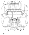
- FIG. 1 illustrates a portion of a prior art aircraft 8 having a cockpit 10 with a flight deck 12 having multiple flight displays 14 and a control system 16, which may be used by the pilot and flight crew to perform flight plan entry and modification by manipulating graphical and textual information on the multiple flight displays 14.
- the flight deck 12 may also include various instruments 18, which may be of conventional type, such as an altimeter, airspeed indicator, attitude indicator, and instrument landing system indicator.
- the multiple flight displays 14 have been illustrated as including physically separate displays 20, 22, 24, and 26, which are separated by physical dividers in the form of both housings 28 around the displays 20-26 and portions of the flight deck 12.
- Each flight display 20-26 is illustrated as including two display devices such as, by way of non-limiting example, color flat-panel LCD screens. Each of the two display devices are separated by a virtual divider 30 located between each of the display devices in each flight display 20-26.
- the display 20 has a left display component 32 and a right display component 34, which is virtually separate from the left display component 32.
- the display 22 has left and right display components 36 and 38
- the display 24 has left and right display components 40 and 42
- the display 26 has left and right display components 44 and 46.
- the displays 20-26 may include information used by the flight crew in flying the aircraft 8.
- the displays 20 and 24 may each be outboard displays which constitute Primary Flight Displays (PFD).
- PFD Primary Flight Displays
- display 20 and display 24 will show substantially identical information, such that the pilot and the co-pilot have access to the same information.
- the displays 22 and 26 may each be inboard displays and may each constitute a Multi-Function Display (MFD).
- the displays 22 and 26 may be used for, among other things, managing the flight plan and carrying out flight path modification.
- a user for example a pilot
- another user for example a co-pilot
- Displays 22 and 26 may be used by more than one person.
- Displays 20-26 need not be coplanar and need not be the same size. Further, it is contemplated that the multiple flight displays 14 may be laid out in any manner.
- One or more cursor control devices 54 and one or more multifunction keyboards 56 may be included in the control system 16 and may be used by one or more flight crew members, including the pilot and co-pilot, to provide input to a processor (not shown) through the cursor control device(s) 54, and receive visual feedback via a graphical display produced on one or more of the multiple flight displays 14.
- a suitable cursor control device 54 may include any device suitable to accept input from the user and to convert that input to a graphical position on any of the multiple flight displays 14.
- Various joysticks, multi-way rockers switches, mice, trackballs, and the like are suitable for this purpose and each user may have separate cursor control devices 54 and keyboards 56.
- a multi-way rocker 58 and trackball 60 have been illustrated as being portions of the cursor control device 54 and various keys and buttons 62 have been illustrated as forming the keyboards 56.
- the pilot and co-pilot may interact with the data elements graphically and textually in accordance with feedback provided by the multiple displays 14.
- the multiple flight displays 14 may thus include one or more cursors 64 positioned in accordance with input from one or more users received via the one or more cursor control devices 54.
- the cursors 64 may be suitably positioned by the one or more users in order to select and graphically edit data elements appearing on any of the multiple flight displays 14.
- the trackball 60 may be operated by a user to move a cursor 64 within a single display device or to move the cursor 64 amongst the multiple displays 14. It is contemplated that the rocker 58 may be a single control for moving the cursor 64 amongst the multiple displays 14 and may do so in multiple directions. More specifically, the rocker 58 may allow the user to move the cursor 64 up a display, down a display, left one or more multiple displays, and right one or more multiple displays as well as combinations of those movements including up-left, up-right, down-left, down-right with a single actuation of the rocker 58.
- both the pilot and copilot may access both of the displays 22 and 26 from each of their respective seats 50 and 52, using distinctive cursors 64.
- Both displays provide the same options and are synchronized by the aircraft display and control system such that, for example, when the pilot is working on, for example, an enroute, high-altitude chart on display 22, the copilot may work on the same chart on display 26, using a different range scale or type of format.
- the pilot and copilot can also work together on the same panel, on the same display, each one using a separate multifunction keyboard 56 and a separate cursor control device 54 to interact with the display system. It is also contemplated that only one cursor 64 may be active within a given display device or window at a time.
- Access to and between the displays 20-26 may be implemented by a "cursor jump" function, which selectively permits each cursor 64 to move about each of the displays 20-26.
- the cursor jump function may be implemented to control movement of the cursor 64 based on a dedicated jump button or buttons, which in the illustrated example is the rocker 58.
- the cursor 64 may jump to another display.
- the cursor 64 may jump to the display immediately left of the display it was previously in.
- the user may select both the left and up option on the rocker 58 and the cursor 64 may move to a display that is up and left from its previous location.
- the cursor jump function may be implemented by cursor location using the trackball 60. For example, if a pilot operates the trackball 60 to move the cursor 64 to the bottom of display 22, and continues the movement of the cursor 64 downwards the cursor 64 will "jump" to display 26. The pilot may then use the cursor 64 and related buttons, knobs, and/or keys to implement any feature available on display 26. It is also contemplated that some combination of the two implementations, that is both the movement of the cursor 64 based on its location and dedicated buttons may be combined to give the user the most control.
- the cursor 64 when a user commands the cursor 64 to jump from one display area to another, the cursor 64 will disappear from its old location and reappear at its new location. The pilot will have to search the expected display area in order to visually re-acquire their cursor 64, especially if the new location is a significant distance from the old one. It is contemplated that the jumping of the cursor 64 to another display may automatically jump the cursor 64 to the center of the second display. Alternatively, it is contemplated that the jumping of the cursor 64 may automatically jump the cursor 64 to a portion of the display. By way of non-limiting example, this may include one of the bottom-left, bottom-right, top-left, or top-right.
- the cursor 64 may be jumped across either the virtual divide 30 and/or the physical divide created by the housing 28 and flight deck 12. In both such instances the cursor 64 may automatically jump to a portion of the next display. These various ways of jumping the cursor 64 may make it even harder for a user to keep track of the cursor 64. For example, if the cursor 64 is jumped across the virtual divide a user may not expect the cursor 64 to then appear at the center of the second display.
- the inventive method may be used in the above described aircraft 8 or any aircraft having multiple flight displays.
- the inventive method uses an indicator or comet tail to help guide the visual scan of the user towards the new cursor location.
- the term "comet tail” as used herein may be any visual indicator capable of indicating a direction of movement of the cursor 64 from its current location to the jump location and is in no way meant to be a limiting term.
- FIGS. 2A-2C graphically illustrate the inventive method of indicating the location of a cursor 64 after the cursor 64 is jumped.
- FIG. 2A illustrates the cursor 64 on the display 34, which may be considered a first flight display.
- the method begins with detecting when the cursor 64 is jumped from a first location on the first flight display 34 to a second location on a second flight display 32.
- FIG. 2B the cursor 64 is illustrated as having been jumped from the first flight display 34 to the upper-left of the display 32, which may be thought of as a second flight display.
- the inventive method includes displaying a comet tail 70 directed toward the second location of the cursor 64 in response to the detected jump.
- the comet tail 70 may be displayed on both the first flight display 34 and second flight display 32 and the comet tail 70 may extend between the first location of the cursor 64, before it jumped, and the second location of the cursor, after the jump.
- the comet tail 70 may be located along a line extending between such first and second locations. It is contemplated that the comet tail 70 may not extend completely between the first and second locations. For example, the comet tail 70 may be displayed on the second flight display only.
- the comet tail 70 may be removed from the flight displays leaving only the cursor 64 in the display 32 as illustrated in FIG. 2C . In this manner, the comet tail 70 may be thought of as being temporarily displayed. Alternatively, it is contemplated that the comet tail 70 may be displayed until the user moves the cursor through operation of one of the cursor control devices 54 or until the user begins to enter information by way of the keyboard 56.
- FIG. 3 is a front view of a portion of the flight deck 12, which is illustrated as including a cursor 64, a second cursor 72, a comet tail 74, a residual cursor marking 76, a third cursor 78, and a comet tail 80 and illustrates a second embodiment of the invention, which contemplates interaction of the multiple cursors 64, 72, and 78 on the multiple flight displays 20-26.
- the cursors 64 and 72 may be understood to be used by the pilot while the third cursor 78 may be thought of as being used by the co-pilot.
- any number of cursors may be located on the multiple flight displays 20-26 at any one time and that those cursors may be used by any of the various users in the aircraft 8.
- the second cursor 72 has been illustrated as having been jumped from the flight display 44 across a portion of the flight deck 12 to a center of the flight display 34.
- the comet tail 74 illustrates the direction of travel of the cursor 72 to the flight display 34.
- the residual cursor 76 may be an optional indicator that may be displayed to illustrate where the cursor 72 jumped from. Such an additional indicator may be particularly helpful where the jump is made across several screens or larger portions of the flight deck 12.
- the cursor 64 may be thought of as being an active cursor, which is being used in the display 38.
- the third cursor 78 is jumped from the first flight display 36 to the second flight display 40 it is also jumped over the third flight display 38 located between the two flight displays 36 and 40.
- comet tail 80 is illustrated in both the first and second flight displays 36 and 40 but not the third flight display 38 having the active cursor 64.
- the comet tail 80 is not displayed in the third display 38 so as to not distract the user using the active cursor 64 or otherwise detract from the flight display 38 having the active cursor 64. It is contemplated that the comet tail may 80 may otherwise be displayed across the third flight display 38 if the cursor 64 was not present or if the cursor 64 was not active.
- the comet tail 80 may be displayed on the third display 38.
- the comet tail may be displayed on additional flight displays the cursor may cross while being jumped.
- the display of the above described comet tails may build upon each other.
- the multiple jumps may be treated as a single jump and the comet tail may be extended through all three displays.
- the three displays may not be linearly aligned it is contemplated the single comet tail through the multiple displays may change directions to indicated the path of travel. Such directional changes may be illustrated as a single continuous comet tail having a smooth curve or a sharp angle.
- a separate comet tail may be shown for the first jump between the first and second display and a second comet tail may be shown for the second jump between the second display and the third display. If additional successive jumps are made additional comet tails may be displayed.
- displaying the comet tail directed toward the second location in response to the detected jump may include displaying an image that visually indicates a direction of travel of the cursor.
- FIGS 4A-4H illustrate additional examples of images, which may be displayed after a cursor 82 jumps from a first location on the flight display 34 to a second location on a flight display 32 in order to visually indicate the direction of travel of the cursor. These examples are non-limiting and are shown for illustrative purposes only as it is contemplated that any image(s) that may visually indicate the direction of travel of the cursor 82 may be used.
- the image displayed may include a comet tail 84 in the form of a pair of lines converging towards the new location of the cursor 82.
- FIG. 4B illustrates a comet tail 86 in the form of two lines both having a decreasing thickness in the direction of travel of the cursor 82.
- FIG. 4C illustrates that the image may include a plurality of shapes having decreasing sizes in the direction of travel of the cursor 82.
- FIG. 4D illustrates a comet tail 90 in the form of plurality of lines having both decreasing size and an increase in frequency in the direction of travel of the cursor 82.
- FIG. 4E illustrates a comet tail 92 in the form of a plurality of arrow heads pointed in the direction of travel of the cursor 82.
- the comet tail 92 also illustrates the arrow heads have an increasing frequency in the direction of travel of the cursor 82 although this need not be the case
- FIG. 4F illustrates a comet tail 94 in the form of a phantom shape having a decreasing thickness in the direction of travel of the cursor 82.
- the comet tail 94 may have a variety of attributes to increase the awareness of the user as to location of the cursor 82 and the direction of travel of the cursor 82.
- the comet tail 94 may have one of a decreasing transparency in the direction of travel, an increasing brightness in the direction of travel, a variation in color in the direction of travel, or any combination thereof.
- comet tails having multiple shapes and lines may also exhibit such features.
- comet tail 96 in the form of a wave having decreasing amplitudes in the direction of travel of the cursor 82. It is contemplated that alternative comet tails may include an image having some pattern, which is not a wave and has either a decreasing amplitude in the direction of travel or an increasing frequency in the direction of travel.
- the display of the image which visually indicates the direction of travel of the cursor, may occur in a variety of manners in order to draw the attention of the user.
- the complete image forming the comet tail may be displayed all at once, that portions of the image may be sequentially displayed, or that portions of the image may be sequentially removed. It is further contemplated, that the comet tail may be only temporarily displayed so as to aid the user in finding the cursor and then not hinder the view of the user.
- displaying the image may also include flashing the displayed image, fading out all or a portion of the displayed image, fading in all or a portion of the displayed image, and varying the image or propagating one or more variations or portions of the image in the direction of travel.
- FIG 4H illustrates a comet tail 98 in the form of two parallel lines having various projections 100. It is contemplated that the projections 100 may be moved along or propagated along the comet tail 98 in the direction of travel of the cursor 82.
- the above described inventive embodiments provide means for a user to visually track the sudden relocation of a cursor when the cursor is jumped from one display to another.
- the described embodiments help guide the visual scan of the user toward the new cursor location and requires less searching by the user to visually reacquire the cursor. This allows the user to find the cursor more quickly and focus on other aspects of flying the plane instead of spending time searching for the jumped cursor.
Landscapes
- Engineering & Computer Science (AREA)
- Theoretical Computer Science (AREA)
- General Engineering & Computer Science (AREA)
- Physics & Mathematics (AREA)
- General Physics & Mathematics (AREA)
- Human Computer Interaction (AREA)
- Computer Hardware Design (AREA)
- Radar, Positioning & Navigation (AREA)
- Remote Sensing (AREA)
- Aviation & Aerospace Engineering (AREA)
- Chemical & Material Sciences (AREA)
- Crystallography & Structural Chemistry (AREA)
- User Interface Of Digital Computer (AREA)
- Position Input By Displaying (AREA)
- Traffic Control Systems (AREA)
Abstract
Description
- Contemporary aircraft cockpits include a flight deck having a display and control system that the pilot and flight crew may use in the operation and control of the aircraft. The aircraft display and control system may include among other things a processor, a cursor control and selection device, a multifunction keyboard, and multiple flight displays. The pilot and flight crew may perform flight plan entry and modification by manipulating graphical and textual information on the multiple flight displays using the cursor control device and the multifunction keyboard. When a pilot commands their cursor to jump from one display to another using the cursor control device, the cursor will disappear from its old location and reappear at its new location requiring the pilot to search the expected display area in order to visually reacquire the cursor.
- In one embodiment, a method of indicating a location of a cursor on a flight deck of an aircraft having multiple flight displays includes detecting when the cursor is jumped from a first location on a first flight display of the multiple flight displays to a second location on a second flight display of the multiple flight displays and displaying a comet tail on at least one of the first flight display and the second flight display directed toward the second location in response to the detected jump.
- In the drawings:
-
FIG. 1 is a perspective view of a portion of a prior art aircraft cockpit with a flight deck having multiple display devices in which the invention may be implemented. -
FIGS. 2A-2C are sequential front views of a flight display ofFIG. 1 showing movement of a cursor and the display of a comet tail in accordance with an embodiment of the present invention. -
FIG. 3 is a front view of a portion of a flight deck ofFIG. 1 illustrating multiple cursors and comet tails in accordance with a second embodiment of the present invention. -
FIGS. 4A-4H are front views of a flight display ofFIG. 1 showing exemplary images forming comet tails in accordance with additional embodiments of the invention. -
FIG. 1 illustrates a portion of a prior art aircraft 8 having acockpit 10 with aflight deck 12 having multiple flight displays 14 and a control system 16, which may be used by the pilot and flight crew to perform flight plan entry and modification by manipulating graphical and textual information on themultiple flight displays 14. Theflight deck 12 may also includevarious instruments 18, which may be of conventional type, such as an altimeter, airspeed indicator, attitude indicator, and instrument landing system indicator. - The multiple flight displays 14 have been illustrated as including physically
separate displays housings 28 around the displays 20-26 and portions of theflight deck 12. Each flight display 20-26 is illustrated as including two display devices such as, by way of non-limiting example, color flat-panel LCD screens. Each of the two display devices are separated by avirtual divider 30 located between each of the display devices in each flight display 20-26. Thus, it may be understood that thedisplay 20 has aleft display component 32 and aright display component 34, which is virtually separate from theleft display component 32. Similarly, thedisplay 22 has left andright display components display 24 has left andright display components 40 and 42, and thedisplay 26 has left andright display components - It is contemplated that the displays 20-26 may include information used by the flight crew in flying the aircraft 8. By way of non-limiting example the
displays display 20 anddisplay 24 will show substantially identical information, such that the pilot and the co-pilot have access to the same information. Thedisplays displays - It will be understood that a user (not shown), for example a pilot, may be present in a seat 50 at the left side of the cockpit, in front of
display 20 and adjacent to display 26, while another user (not shown), for example a co-pilot, may be present at the right side of the cockpit in a seat 52, in front ofdisplay 24 and adjacent to display 26.Displays - One or more
cursor control devices 54 and one or more multifunction keyboards 56 may be included in the control system 16 and may be used by one or more flight crew members, including the pilot and co-pilot, to provide input to a processor (not shown) through the cursor control device(s) 54, and receive visual feedback via a graphical display produced on one or more of themultiple flight displays 14. A suitablecursor control device 54 may include any device suitable to accept input from the user and to convert that input to a graphical position on any of the multiple flight displays 14. Various joysticks, multi-way rockers switches, mice, trackballs, and the like are suitable for this purpose and each user may have separatecursor control devices 54 and keyboards 56. - By way of a non-limiting example, a multi-way rocker 58 and trackball 60 have been illustrated as being portions of the
cursor control device 54 and various keys and buttons 62 have been illustrated as forming the keyboards 56. Through use of the cursor control device(s) 54 and multifunction keyboard(s) 56, the pilot and co-pilot may interact with the data elements graphically and textually in accordance with feedback provided by themultiple displays 14. In this manner it will be understood that the multiple flight displays 14 may thus include one or more cursors 64 positioned in accordance with input from one or more users received via the one or morecursor control devices 54. In general, the cursors 64 may be suitably positioned by the one or more users in order to select and graphically edit data elements appearing on any of the multiple flight displays 14. The trackball 60 may be operated by a user to move a cursor 64 within a single display device or to move the cursor 64 amongst themultiple displays 14. It is contemplated that the rocker 58 may be a single control for moving the cursor 64 amongst themultiple displays 14 and may do so in multiple directions. More specifically, the rocker 58 may allow the user to move the cursor 64 up a display, down a display, left one or more multiple displays, and right one or more multiple displays as well as combinations of those movements including up-left, up-right, down-left, down-right with a single actuation of the rocker 58. - It is contemplated that both the pilot and copilot may access both of the
displays display 22, the copilot may work on the same chart ondisplay 26, using a different range scale or type of format. The pilot and copilot can also work together on the same panel, on the same display, each one using a separate multifunction keyboard 56 and a separatecursor control device 54 to interact with the display system. It is also contemplated that only one cursor 64 may be active within a given display device or window at a time. - Access to and between the displays 20-26 may be implemented by a "cursor jump" function, which selectively permits each cursor 64 to move about each of the displays 20-26. In one example, the cursor jump function may be implemented to control movement of the cursor 64 based on a dedicated jump button or buttons, which in the illustrated example is the rocker 58. When a user operates the rocker 58 the cursor 64 may jump to another display. By way of a non-limiting example, if the left portion of the rocker 58 is selected by the user, the cursor 64 may jump to the display immediately left of the display it was previously in. By way of an additional non-limiting example, the user may select both the left and up option on the rocker 58 and the cursor 64 may move to a display that is up and left from its previous location. Alternatively, the cursor jump function may be implemented by cursor location using the trackball 60. For example, if a pilot operates the trackball 60 to move the cursor 64 to the bottom of
display 22, and continues the movement of the cursor 64 downwards the cursor 64 will "jump" to display 26. The pilot may then use the cursor 64 and related buttons, knobs, and/or keys to implement any feature available ondisplay 26. It is also contemplated that some combination of the two implementations, that is both the movement of the cursor 64 based on its location and dedicated buttons may be combined to give the user the most control. - Regardless of the manner in which the cursor 64 is jumped by the user, when a user commands the cursor 64 to jump from one display area to another, the cursor 64 will disappear from its old location and reappear at its new location. The pilot will have to search the expected display area in order to visually re-acquire their cursor 64, especially if the new location is a significant distance from the old one. It is contemplated that the jumping of the cursor 64 to another display may automatically jump the cursor 64 to the center of the second display. Alternatively, it is contemplated that the jumping of the cursor 64 may automatically jump the cursor 64 to a portion of the display. By way of non-limiting example, this may include one of the bottom-left, bottom-right, top-left, or top-right. It is also contemplated that the cursor 64 may be jumped across either the
virtual divide 30 and/or the physical divide created by thehousing 28 andflight deck 12. In both such instances the cursor 64 may automatically jump to a portion of the next display. These various ways of jumping the cursor 64 may make it even harder for a user to keep track of the cursor 64. For example, if the cursor 64 is jumped across the virtual divide a user may not expect the cursor 64 to then appear at the center of the second display. - The inventive method may be used in the above described aircraft 8 or any aircraft having multiple flight displays. The inventive method uses an indicator or comet tail to help guide the visual scan of the user towards the new cursor location. The term "comet tail" as used herein may be any visual indicator capable of indicating a direction of movement of the cursor 64 from its current location to the jump location and is in no way meant to be a limiting term.
-
FIGS. 2A-2C graphically illustrate the inventive method of indicating the location of a cursor 64 after the cursor 64 is jumped.FIG. 2A illustrates the cursor 64 on thedisplay 34, which may be considered a first flight display. The method begins with detecting when the cursor 64 is jumped from a first location on thefirst flight display 34 to a second location on asecond flight display 32. InFIG. 2B the cursor 64 is illustrated as having been jumped from thefirst flight display 34 to the upper-left of thedisplay 32, which may be thought of as a second flight display. When it is detected that a jump of the cursor 64 has occurred, the inventive method includes displaying acomet tail 70 directed toward the second location of the cursor 64 in response to the detected jump. - As illustrated, the
comet tail 70 may be displayed on both thefirst flight display 34 andsecond flight display 32 and thecomet tail 70 may extend between the first location of the cursor 64, before it jumped, and the second location of the cursor, after the jump. Thecomet tail 70 may be located along a line extending between such first and second locations. It is contemplated that thecomet tail 70 may not extend completely between the first and second locations. For example, thecomet tail 70 may be displayed on the second flight display only. - After the
comet tail 70 has been displayed for some increment of time it may be removed from the flight displays leaving only the cursor 64 in thedisplay 32 as illustrated inFIG. 2C . In this manner, thecomet tail 70 may be thought of as being temporarily displayed. Alternatively, it is contemplated that thecomet tail 70 may be displayed until the user moves the cursor through operation of one of thecursor control devices 54 or until the user begins to enter information by way of the keyboard 56. -
FIG. 3 is a front view of a portion of theflight deck 12, which is illustrated as including a cursor 64, a second cursor 72, a comet tail 74, a residual cursor marking 76, athird cursor 78, and acomet tail 80 and illustrates a second embodiment of the invention, which contemplates interaction of themultiple cursors 64, 72, and 78 on the multiple flight displays 20-26. For illustrative purposes, the cursors 64 and 72 may be understood to be used by the pilot while thethird cursor 78 may be thought of as being used by the co-pilot. Such an example will be understood to be non-limiting as it is contemplated that any number of cursors may be located on the multiple flight displays 20-26 at any one time and that those cursors may be used by any of the various users in the aircraft 8. - The second cursor 72 has been illustrated as having been jumped from the
flight display 44 across a portion of theflight deck 12 to a center of theflight display 34. The comet tail 74 illustrates the direction of travel of the cursor 72 to theflight display 34. It is contemplated that theresidual cursor 76 may be an optional indicator that may be displayed to illustrate where the cursor 72 jumped from. Such an additional indicator may be particularly helpful where the jump is made across several screens or larger portions of theflight deck 12. - The cursor 64 may be thought of as being an active cursor, which is being used in the
display 38. When thethird cursor 78 is jumped from thefirst flight display 36 to the second flight display 40 it is also jumped over thethird flight display 38 located between the twoflight displays 36 and 40. It is illustrated thatcomet tail 80 is illustrated in both the first and second flight displays 36 and 40 but not thethird flight display 38 having the active cursor 64. Thecomet tail 80 is not displayed in thethird display 38 so as to not distract the user using the active cursor 64 or otherwise detract from theflight display 38 having the active cursor 64. It is contemplated that the comet tail may 80 may otherwise be displayed across thethird flight display 38 if the cursor 64 was not present or if the cursor 64 was not active. Further, if the cursor 64 on thethird display 38 was controlled by the same user as thecursor 78, which was being jumped over thatdisplay 38, then it is contemplated that thecomet tail 80 may be displayed on thethird display 38. Thus, it is contemplated that the comet tail may be displayed on additional flight displays the cursor may cross while being jumped. - Further, if it will be understood that the display of the above described comet tails may build upon each other. By way of non-limiting example, if a cursor is jumped from a first display to a second display and then to a third display in succession the multiple jumps may be treated as a single jump and the comet tail may be extended through all three displays. As the three displays may not be linearly aligned it is contemplated the single comet tail through the multiple displays may change directions to indicated the path of travel. Such directional changes may be illustrated as a single continuous comet tail having a smooth curve or a sharp angle. By way of a second non-limiting example, if the cursor makes the same successive jumps from the first display to the third display a separate comet tail may be shown for the first jump between the first and second display and a second comet tail may be shown for the second jump between the second display and the third display. If additional successive jumps are made additional comet tails may be displayed.
- It may be understood that displaying the comet tail directed toward the second location in response to the detected jump may include displaying an image that visually indicates a direction of travel of the cursor.
FIGS 4A-4H illustrate additional examples of images, which may be displayed after acursor 82 jumps from a first location on theflight display 34 to a second location on aflight display 32 in order to visually indicate the direction of travel of the cursor. These examples are non-limiting and are shown for illustrative purposes only as it is contemplated that any image(s) that may visually indicate the direction of travel of thecursor 82 may be used. - As illustrated in
FIG. 4A when thecursor 82 is jumped, the image displayed may include acomet tail 84 in the form of a pair of lines converging towards the new location of thecursor 82.FIG. 4B illustrates acomet tail 86 in the form of two lines both having a decreasing thickness in the direction of travel of thecursor 82.FIG. 4C illustrates that the image may include a plurality of shapes having decreasing sizes in the direction of travel of thecursor 82.FIG. 4D illustrates acomet tail 90 in the form of plurality of lines having both decreasing size and an increase in frequency in the direction of travel of thecursor 82.FIG. 4E illustrates acomet tail 92 in the form of a plurality of arrow heads pointed in the direction of travel of thecursor 82. Thecomet tail 92 also illustrates the arrow heads have an increasing frequency in the direction of travel of thecursor 82 although this need not be the case -
FIG. 4F illustrates acomet tail 94 in the form of a phantom shape having a decreasing thickness in the direction of travel of thecursor 82. It is contemplated that thecomet tail 94 may have a variety of attributes to increase the awareness of the user as to location of thecursor 82 and the direction of travel of thecursor 82. For example, thecomet tail 94 may have one of a decreasing transparency in the direction of travel, an increasing brightness in the direction of travel, a variation in color in the direction of travel, or any combination thereof. It is also contemplated that comet tails having multiple shapes and lines may also exhibit such features.FIG. 4G illustrates acomet tail 96 in the form of a wave having decreasing amplitudes in the direction of travel of thecursor 82. It is contemplated that alternative comet tails may include an image having some pattern, which is not a wave and has either a decreasing amplitude in the direction of travel or an increasing frequency in the direction of travel. - There may also be a multitude of ways to display the images forming the various comet tails. By way of non-limiting examples, it is contemplated that the display of the image, which visually indicates the direction of travel of the cursor, may occur in a variety of manners in order to draw the attention of the user. By way of non-limiting examples, it is contemplated that the complete image forming the comet tail may be displayed all at once, that portions of the image may be sequentially displayed, or that portions of the image may be sequentially removed. It is further contemplated, that the comet tail may be only temporarily displayed so as to aid the user in finding the cursor and then not hinder the view of the user. It is further contemplated that displaying the image may also include flashing the displayed image, fading out all or a portion of the displayed image, fading in all or a portion of the displayed image, and varying the image or propagating one or more variations or portions of the image in the direction of travel. For example,
FIG 4H illustrates acomet tail 98 in the form of two parallel lines havingvarious projections 100. It is contemplated that theprojections 100 may be moved along or propagated along thecomet tail 98 in the direction of travel of thecursor 82. - The above described inventive embodiments provide means for a user to visually track the sudden relocation of a cursor when the cursor is jumped from one display to another. The described embodiments help guide the visual scan of the user toward the new cursor location and requires less searching by the user to visually reacquire the cursor. This allows the user to find the cursor more quickly and focus on other aspects of flying the plane instead of spending time searching for the jumped cursor.
- This written description uses examples to disclose the invention, including the best mode, and also to enable any person skilled in the art to practice the invention, including making and using any devices or systems and performing any incorporated methods. The patentable scope of the invention is defined by the claims, and may include other examples that occur to those skilled in the art. Such other examples are intended to be within the scope of the claims if they have structural elements that do not differ from the literal language of the claims, or if they include equivalent structural elements with insubstantial differences from the literal languages of the claims.
Claims (14)
- A method of indicating a location of a cursor (64) on a flight deck (12) of an aircraft (8) having multiple flight displays, the method comprising:detecting when the cursor is jumped from a first location on a first flight display (34) of the multiple flight displays to a second location on a second flight display (32) of the multiple flight displays; anddisplaying a comet tail (70) on at least one of the first flight display and the second flight display directed toward the second location in response to the detected jump.
- The method of claim 1 wherein the comet tail (70) is displayed on both the first flight display (34) and the second flight display (32).
- The method of claim 2 wherein the comet tail (70) extends between the first location and the second location.
- The method of any preceding claim, wherein the comet tail (70) is temporarily displayed.
- The method of any preceding claim, wherein the comet tail (70) is located along a line extending between the first and second locations.
- The method of any preceding claim, wherein the second location is in the center of the second display (32).
- The method of any preceding claim, wherein at least two of the multiple flight displays (32,34) are a single physical display with a virtual divider (30) and the cursor (64) is jumped across the virtual divider.
- The method of any preceding claim, wherein at least two of the multiple flight displays are separate physical displays with a physical divider and the cursor is jumped across the physical divider.
- The method of any preceding claim, wherein when the cursor (78) is jumped over a third flight display (38) located between the first (36) and second flight displays (40).
- The method of claim 9 wherein the comet tail (80) is displayed across the third flight display (38) when it is does not contain a second cursor (64) of a second pilot.
- The method of any preceding claim, wherein the displaying of the comet tail (70) comprises displaying an image that visually indicates direction of travel of the cursor (64).
- The method of any preceding claim, wherein the image comprises at least one of:a) a line and a shape (86) having a decreasing thickness in the direction of travel;b) a plurality of arrow heads (92);c) a plurality of lines (90);d) a plurality of shapes;e) a line and a shape (94) having a decreasing transparency in the direction of travel;f) a line and a shape having an increasing brightness in the direction of travel;g) a line and a shape having a variation in color in the direction of travel;h) a wave and a pattern (96) of decreasing amplitude in the direction of travel; andi) a wave and pattern of increasing frequency in the direction of travel.
- The method of any preceding claim, wherein the display of the image comprises at least one of:a) displaying the complete image all at once;b) sequentially displaying portions of the image; andc) sequentially removing portions of the image.
- The method of claim 13 wherein displaying the image further comprises at least one of:a) flashing the displayed image;b) fading out the displayed image;c) fading in the displayed image; andd) varying the displayed image in the direction of travel.
Applications Claiming Priority (1)
| Application Number | Priority Date | Filing Date | Title |
|---|---|---|---|
| US13/169,821 US9201567B2 (en) | 2011-06-27 | 2011-06-27 | Method for indicating a cursor location on a flight deck having multiple flight displays |
Publications (2)
| Publication Number | Publication Date |
|---|---|
| EP2541387A2 true EP2541387A2 (en) | 2013-01-02 |
| EP2541387A3 EP2541387A3 (en) | 2015-09-23 |
Family
ID=46465048
Family Applications (1)
| Application Number | Title | Priority Date | Filing Date |
|---|---|---|---|
| EP12173107.9A Ceased EP2541387A3 (en) | 2011-06-27 | 2012-06-22 | A method for indicating a cursor location on a flight deck having multiple flight displays |
Country Status (6)
| Country | Link |
|---|---|
| US (1) | US9201567B2 (en) |
| EP (1) | EP2541387A3 (en) |
| JP (1) | JP6027350B2 (en) |
| CN (1) | CN102915175B (en) |
| BR (1) | BR102012015793A2 (en) |
| CA (1) | CA2781035C (en) |
Cited By (1)
| Publication number | Priority date | Publication date | Assignee | Title |
|---|---|---|---|---|
| EP3418873A4 (en) * | 2016-02-18 | 2019-01-16 | Sony Corporation | INFORMATION PROCESSING DEVICE, INFORMATION PROCESSING METHOD, AND PROGRAM |
Families Citing this family (22)
| Publication number | Priority date | Publication date | Assignee | Title |
|---|---|---|---|---|
| JPH0628632Y2 (en) | 1986-08-30 | 1994-08-03 | 立川ブラインド工業株式会社 | Folding Shutter |
| JPH0616075Y2 (en) | 1987-06-12 | 1994-04-27 | 立川ブラインド工業株式会社 | Folding shutter |
| CN108230988B (en) * | 2012-02-08 | 2022-02-01 | 三星电子株式会社 | Display device |
| CN104603732B (en) * | 2012-08-28 | 2018-12-04 | Eizo株式会社 | Display control method, computer program, display control unit and image display system |
| US9542147B2 (en) * | 2013-12-16 | 2017-01-10 | Lockheed Martin Corporation | Peripheral vision hover drift cueing |
| US9366546B2 (en) | 2014-02-24 | 2016-06-14 | Lockheed Martin Corporation | Projected synthetic vision |
| US9563276B2 (en) | 2014-03-26 | 2017-02-07 | Lockheed Martin Corporation | Tactile and peripheral vision combined modality hover drift cueing |
| WO2016018331A1 (en) * | 2014-07-31 | 2016-02-04 | Hewlett-Packard Development Company, L.P. | Cursor locator |
| JP2016103173A (en) * | 2014-11-28 | 2016-06-02 | アイシン・エィ・ダブリュ株式会社 | Screen display system, method, and program |
| EP3046012A1 (en) * | 2015-01-15 | 2016-07-20 | Siemens Schweiz AG | Method for highlighting a mouse pointer in a screen display |
| US10474315B2 (en) * | 2015-06-26 | 2019-11-12 | The Boeing Company | Cursor enhancement effects |
| US20180107358A1 (en) * | 2016-10-17 | 2018-04-19 | International Business Machines Corporation | Multiple-display unification system and method |
| JP6508173B2 (en) * | 2016-11-25 | 2019-05-08 | トヨタ自動車株式会社 | Vehicle display device |
| WO2018227623A1 (en) * | 2017-06-16 | 2018-12-20 | 深圳市大疆创新科技有限公司 | Control method, aircraft system, and display terminal |
| US11440675B2 (en) * | 2018-05-21 | 2022-09-13 | Gulfstream Aerospace Corporation | Aircraft flight guidance panels with a display disposed between two input portions |
| US11010013B2 (en) | 2018-10-29 | 2021-05-18 | International Business Machines Corporation | Providing visual control guidance on a display |
| US10901570B2 (en) * | 2018-11-26 | 2021-01-26 | International Business Machines Corporation | Input placement control guidance on a display |
| USD907565S1 (en) * | 2019-01-03 | 2021-01-12 | Bell Textron Inc. | Instrument panel |
| US10866654B1 (en) * | 2019-08-28 | 2020-12-15 | Lenovo (Singapore) Pte. Ltd. | Presentation of indication of location of mouse cursor based on jiggling of mouse cursor |
| US11893541B2 (en) * | 2020-10-15 | 2024-02-06 | Prezi, Inc. | Meeting and collaborative canvas with image pointer |
| CN116974496A (en) * | 2022-04-21 | 2023-10-31 | 华为技术有限公司 | A multi-screen interaction method and electronic device |
| US12380865B2 (en) * | 2023-05-18 | 2025-08-05 | AUO Corporation | Cockpit display system |
Citations (2)
| Publication number | Priority date | Publication date | Assignee | Title |
|---|---|---|---|---|
| US6774886B2 (en) * | 2000-12-14 | 2004-08-10 | Matsushita Electric Industrial Co., Ltd. | Display system, cursor position indication method, and recording medium |
| US20090284532A1 (en) * | 2008-05-16 | 2009-11-19 | Apple Inc. | Cursor motion blurring |
Family Cites Families (18)
| Publication number | Priority date | Publication date | Assignee | Title |
|---|---|---|---|---|
| US5214414A (en) * | 1991-04-12 | 1993-05-25 | International Business Machines Corp. | Cursor for lcd displays |
| WO1993022758A1 (en) * | 1992-05-07 | 1993-11-11 | Kensington Microware Limited | Method and apparatus for cursor positioning |
| JPH1173294A (en) * | 1997-08-25 | 1999-03-16 | Internatl Business Mach Corp <Ibm> | Pointing device and method therefor |
| US6392675B1 (en) * | 1999-02-24 | 2002-05-21 | International Business Machines Corporation | Variable speed cursor movement |
| US6381519B1 (en) * | 2000-09-19 | 2002-04-30 | Honeywell International Inc. | Cursor management on a multiple display electronic flight instrumentation system |
| US7724240B2 (en) | 2000-10-06 | 2010-05-25 | Honeywell International Inc. | Multifunction keyboard for advanced cursor driven avionic flight decks |
| US6784869B1 (en) * | 2000-11-15 | 2004-08-31 | The Boeing Company | Cursor and display management system for multi-function control and display system |
| US20020063740A1 (en) * | 2000-11-30 | 2002-05-30 | Forlenza Randolph Michael | Method to unobscure vision caused by the mouse pointer positioning within a document being displayed by a computer system |
| US7385584B2 (en) * | 2001-02-07 | 2008-06-10 | International Business Machines Corporation | Automated keyboard mouse switch |
| US7142192B2 (en) * | 2002-12-12 | 2006-11-28 | Nvidia Corporation | Cursor locator for multi-monitor systems |
| US7730430B2 (en) * | 2003-01-24 | 2010-06-01 | Microsoft Corporation | High density cursor system and method |
| US7365738B2 (en) * | 2003-12-02 | 2008-04-29 | International Business Machines Corporation | Guides and indicators for eye movement monitoring systems |
| US20060143580A1 (en) * | 2004-12-20 | 2006-06-29 | International Business Machines Corporation | Method and system for quick screen switching in a multi-monitor environment |
| JP2007087211A (en) * | 2005-09-22 | 2007-04-05 | Toshiba Tec Corp | IC tag communication system |
| US8681109B2 (en) | 2007-02-28 | 2014-03-25 | Honeywell International Inc. | Display system and method including a stimuli-sensitive multi-function display with consolidated control functions |
| US8403753B2 (en) * | 2008-09-30 | 2013-03-26 | Nintendo Co., Ltd. | Computer-readable storage medium storing game program, game apparatus, and processing method |
| JP5509757B2 (en) * | 2009-09-17 | 2014-06-04 | セイコーエプソン株式会社 | Information processing apparatus, display control method, and program |
| US20110083108A1 (en) * | 2009-10-05 | 2011-04-07 | Microsoft Corporation | Providing user interface feedback regarding cursor position on a display screen |
-
2011
- 2011-06-27 US US13/169,821 patent/US9201567B2/en not_active Expired - Fee Related
-
2012
- 2012-06-22 CA CA2781035A patent/CA2781035C/en not_active Expired - Fee Related
- 2012-06-22 EP EP12173107.9A patent/EP2541387A3/en not_active Ceased
- 2012-06-26 BR BRBR102012015793-4A patent/BR102012015793A2/en active Search and Examination
- 2012-06-26 JP JP2012142553A patent/JP6027350B2/en not_active Expired - Fee Related
- 2012-06-27 CN CN201210323681.6A patent/CN102915175B/en not_active Expired - Fee Related
Patent Citations (2)
| Publication number | Priority date | Publication date | Assignee | Title |
|---|---|---|---|---|
| US6774886B2 (en) * | 2000-12-14 | 2004-08-10 | Matsushita Electric Industrial Co., Ltd. | Display system, cursor position indication method, and recording medium |
| US20090284532A1 (en) * | 2008-05-16 | 2009-11-19 | Apple Inc. | Cursor motion blurring |
Cited By (1)
| Publication number | Priority date | Publication date | Assignee | Title |
|---|---|---|---|---|
| EP3418873A4 (en) * | 2016-02-18 | 2019-01-16 | Sony Corporation | INFORMATION PROCESSING DEVICE, INFORMATION PROCESSING METHOD, AND PROGRAM |
Also Published As
| Publication number | Publication date |
|---|---|
| US20120327104A1 (en) | 2012-12-27 |
| JP6027350B2 (en) | 2016-11-16 |
| EP2541387A3 (en) | 2015-09-23 |
| CN102915175A (en) | 2013-02-06 |
| CA2781035C (en) | 2019-09-17 |
| CA2781035A1 (en) | 2012-12-27 |
| US9201567B2 (en) | 2015-12-01 |
| CN102915175B (en) | 2017-04-26 |
| BR102012015793A2 (en) | 2014-12-09 |
| JP2013012199A (en) | 2013-01-17 |
Similar Documents
| Publication | Publication Date | Title |
|---|---|---|
| US9201567B2 (en) | Method for indicating a cursor location on a flight deck having multiple flight displays | |
| EP2698705A2 (en) | Methods for displaying on a graphical user interface | |
| US6980198B1 (en) | Multifunction keyboard for advanced cursor driven avionic flight decks | |
| CN104298232B (en) | Display system and method for providing a display with integrated autonomous driving functionality | |
| US8712605B1 (en) | Apparatus for touch screen avionic device | |
| US6381519B1 (en) | Cursor management on a multiple display electronic flight instrumentation system | |
| US9032319B1 (en) | Methods, systems, and apparatus for handling of flight deck data | |
| EP2362183B1 (en) | Aircraft charting system with multi-touch interaction gestures for managing a route of an aircraft | |
| JP6050040B2 (en) | Simplified user interface for aircraft | |
| US7724240B2 (en) | Multifunction keyboard for advanced cursor driven avionic flight decks | |
| US20140132528A1 (en) | Aircraft haptic touch screen and method for operating same | |
| US20060244636A1 (en) | Multiple miniature avionic displays | |
| EP2431713B1 (en) | Display system and method including a stimuli-sensitive multi-function display with consolidated control functions | |
| EP2587350A2 (en) | Method for determining valid touch screen inputs | |
| US20180181299A1 (en) | Cursor control for aircraft display device | |
| US9128594B1 (en) | Touch interfaces and controls for aviation displays | |
| EP1965174B1 (en) | Stimuli-sensitive display screen with consolidated control functions | |
| Thomas | Performance, characteristics, and error rates of cursor control devices for aircraft cockpit interaction | |
| CN103577039B (en) | For the method in the geographical position for showing airborne vehicle | |
| Dodd et al. | Touch on the flight deck: The impact of display location, size, touch technology & turbulence on pilot performance | |
| GB2514640A (en) | Control panel for use in controlling a large area display | |
| US8223119B1 (en) | System and apparatus for graphical flight display manipulation | |
| Sarter | Information Management on the Flight Deck of Highly Automated Aircraft | |
| EP3023967A1 (en) | Methods, systems, and computer readable media for cursor and text entry for aircraft interface simulation | |
| EP1757520A2 (en) | Multifunction keyboard for cursor driven avionic flight decks |
Legal Events
| Date | Code | Title | Description |
|---|---|---|---|
| PUAI | Public reference made under article 153(3) epc to a published international application that has entered the european phase |
Free format text: ORIGINAL CODE: 0009012 |
|
| AK | Designated contracting states |
Kind code of ref document: A2 Designated state(s): AL AT BE BG CH CY CZ DE DK EE ES FI FR GB GR HR HU IE IS IT LI LT LU LV MC MK MT NL NO PL PT RO RS SE SI SK SM TR |
|
| AX | Request for extension of the european patent |
Extension state: BA ME |
|
| PUAL | Search report despatched |
Free format text: ORIGINAL CODE: 0009013 |
|
| AK | Designated contracting states |
Kind code of ref document: A3 Designated state(s): AL AT BE BG CH CY CZ DE DK EE ES FI FR GB GR HR HU IE IS IT LI LT LU LV MC MK MT NL NO PL PT RO RS SE SI SK SM TR |
|
| AX | Request for extension of the european patent |
Extension state: BA ME |
|
| RIC1 | Information provided on ipc code assigned before grant |
Ipc: G01C 23/00 20060101ALI20150819BHEP Ipc: G06F 3/048 20130101AFI20150819BHEP |
|
| 17P | Request for examination filed |
Effective date: 20160323 |
|
| RBV | Designated contracting states (corrected) |
Designated state(s): AL AT BE BG CH CY CZ DE DK EE ES FI FR GB GR HR HU IE IS IT LI LT LU LV MC MK MT NL NO PL PT RO RS SE SI SK SM TR |
|
| 17Q | First examination report despatched |
Effective date: 20170317 |
|
| STAA | Information on the status of an ep patent application or granted ep patent |
Free format text: STATUS: THE APPLICATION HAS BEEN REFUSED |
|
| 18R | Application refused |
Effective date: 20181213 |