EP2541374A2 - Pointing device - Google Patents
Pointing device Download PDFInfo
- Publication number
- EP2541374A2 EP2541374A2 EP12155120A EP12155120A EP2541374A2 EP 2541374 A2 EP2541374 A2 EP 2541374A2 EP 12155120 A EP12155120 A EP 12155120A EP 12155120 A EP12155120 A EP 12155120A EP 2541374 A2 EP2541374 A2 EP 2541374A2
- Authority
- EP
- European Patent Office
- Prior art keywords
- main body
- fixed base
- pointing device
- hinge portion
- outer covering
- Prior art date
- Legal status (The legal status is an assumption and is not a legal conclusion. Google has not performed a legal analysis and makes no representation as to the accuracy of the status listed.)
- Granted
Links
- 238000006073 displacement reaction Methods 0.000 claims abstract description 31
- 238000012545 processing Methods 0.000 claims abstract description 20
- 230000000149 penetrating effect Effects 0.000 claims description 2
- 230000001960 triggered effect Effects 0.000 claims description 2
- 238000010586 diagram Methods 0.000 description 15
- 208000027418 Wounds and injury Diseases 0.000 description 5
- 230000006378 damage Effects 0.000 description 5
- 238000005516 engineering process Methods 0.000 description 5
- 208000014674 injury Diseases 0.000 description 5
- 210000000707 wrist Anatomy 0.000 description 5
- 238000013461 design Methods 0.000 description 3
- 230000003867 tiredness Effects 0.000 description 3
- 208000016255 tiredness Diseases 0.000 description 3
- 230000000694 effects Effects 0.000 description 2
- 238000004891 communication Methods 0.000 description 1
- 238000012986 modification Methods 0.000 description 1
- 230000004048 modification Effects 0.000 description 1
- 210000003205 muscle Anatomy 0.000 description 1
- 238000012546 transfer Methods 0.000 description 1
Images


Classifications
-
- G—PHYSICS
- G06—COMPUTING; CALCULATING OR COUNTING
- G06F—ELECTRIC DIGITAL DATA PROCESSING
- G06F3/00—Input arrangements for transferring data to be processed into a form capable of being handled by the computer; Output arrangements for transferring data from processing unit to output unit, e.g. interface arrangements
- G06F3/01—Input arrangements or combined input and output arrangements for interaction between user and computer
- G06F3/03—Arrangements for converting the position or the displacement of a member into a coded form
- G06F3/033—Pointing devices displaced or positioned by the user, e.g. mice, trackballs, pens or joysticks; Accessories therefor
- G06F3/0354—Pointing devices displaced or positioned by the user, e.g. mice, trackballs, pens or joysticks; Accessories therefor with detection of 2D relative movements between the device, or an operating part thereof, and a plane or surface, e.g. 2D mice, trackballs, pens or pucks
- G06F3/03543—Mice or pucks
-
- G—PHYSICS
- G06—COMPUTING; CALCULATING OR COUNTING
- G06F—ELECTRIC DIGITAL DATA PROCESSING
- G06F2203/00—Indexing scheme relating to G06F3/00 - G06F3/048
- G06F2203/033—Indexing scheme relating to G06F3/033
- G06F2203/0332—Ergonomic shaped mouse adjustable to suit one of both hands
Definitions
- the present invention relates to a pointing device, and more particularly relates to a pointing device that could depend on the different requirements of users to change to a mouse-operating mode or a holding-a-pen-operating mode.
- a pointing device such as a mouse device is commonly used, and the pointing device is an essential input device for the computer system of nowadays. Therefore, almost all users would use the mouse device configured to input instructions and operate the computer system. In order to make the users utilize the mouse device comfortably, so that the manufacturers are improving its functions, appearance and flexibility. For example, the displacement of the cursor which displayed on the computer screen is operated by sensing module of the mouse device that has replaced the trackball of the mouse device in early periods. Furthermore, a roller wheel is disposed between the two buttons of the mouse device, so as to obtain superior convenience while the users using the mouse device.
- the use of the mouse device at present that is the user puts its palm placing onto the surface of the mouse device and configured to be hold the whole mouse device such the above-mentioned using manner that causes the muscles and joints of the users' hand easily tired after a long time.
- the forgoing using manner that also causes the injury with the user's wrist or hand due to the user's wrist lacks the point of application during the long time.
- the existing mouse device has evolved with ergonomics, or the mouse device is known has evolved with the holding-pen using manner, so as to retard the tiredness of the users' hand.
- the user uses the forgoing mouse device who still maintains the same posture during operation, which causes the problem as injury with the user's wrist and hand yet.
- the present invention is directed to a pointing device for solving the problems of the prior art with tiredness of the users' hand, even injury with the user's wrist due to the user who maintains the same posture during use the existing mouse device after the long time.
- the present invention discloses a pointing device which used with a computer device, and the pointing device includes a fixed base and a main body which is selectively rotated to a first angle or a second angle.
- the fixed base of the pointing device includes a first hinge portion and a sensing displacement module, the first hinge portion is located on one end of the fixed base, and the sensing displacement module is electrically located in the fixed base to generate a displacement signal.
- the main body of the pointing device includes a second hinge portion and a processing unit, the second hinge portion is located on one end of the main body and pivots on the first hinge portion, and the processing unit is electrically located in the main body and is electrically connected to the sensing displacement module for receiving the displacement signal and transmitting the displacement signal to the computer device.
- the pointing device of the present invention further includes an outer covering, wherein the outer covering has an accommodating space for holding the fixed base and the main body in the outer covering.
- the effectiveness of the present invention is that users can able to pivot the fixed base and main body of the pointing device to a first angle or a second angle depending on the users' requirement, so as to change the operating manner of the pointing device. Therefore, the invention effectively avoid the user who maintains the same posture during a long time, so as to protect the users' hand would not injure, even causing sport injury with the user's wrist.
- FIG. 1 and FIG. 2 respectively shows the front view and the rear view of three-dimensional diagrams of the first embodiment of the present invention
- FIG. 3 shows the circuit block diagram of the first embodiment of the present invention.
- a pointing device 100 includes a fixed base 110 and a main body 120.
- one end of the fixed base 110 has a first hinge portion 111
- one end of the main body 120 has a second hinge portion 121.
- the fixed base 110 and the main body 120 pivot each other by the first hinge portion 111 and the second hinge portion 121.
- a sensing displacement module 140 is electrically mounted in the fixed base 110, and the sensing displacement module 140 further includes a light source 143 and a light sensor 145, and additionally, the fixed base 110 has a through hole 141.
- the light source 143 radiates a sensing light penetrating the through hole 141
- the light sensor 145 receives the reflective light of the sensing light to generate a displacement signal.
- a person skilled in the art can generate a displacement signal by utilizing various sensing displacement technologies according to his/her experience or design requirements, those technologies are not limited in the disclosed embodiment.
- the main body 120 has a processing unit 123, and the sensing displacement module 140 is electrically connected to the processing unit 120, such that the processing unit 123 receives the displacement signal generated from the sensing displacement module 140.
- the main body 120 has two buttons 127 which are electrically connected to the processing unit 123 for input control.
- a person skilled in the art can rely on his/her specific requirements and selectively change amount or structure of the button, and those technologies are not limited in the disclosed embodiment.
- the pointing device 100 of the first embodiment further includes a connecting wire 151, and the connecting wire 151 is electrically connected to the pointing device 100 with a computer device 200. Therefore, the processing unit 123 can transfer the displacement signal to the computer device 200 by the connecting wire 151, and users can operate the computer device 200 by the pointing device 100 of the first embodiment.
- the communication between the pointing device 100 and the computer device 200 can also be conducted by cordless manner, so called wireless, such as Bluetooth, satellite etc.
- the pointing device 100 of the first embodiment further includes a holding element 130 which could plug into the hole 125, and the holding element 130 could be a pen in the disclosed embodiment.
- the bore diameter of the hole 125 can be designed substantially same as the rod diameter of the pencil or pen on the market, therefore users could plug a pen, which is carried along by the users into the hole 125.
- the holding element 130 is not limited to a pen, it can be an object which is designed, shaped or manufactured for users to hold.
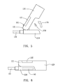
- FIG. 4A and FIG. 5 respectively shows the front view of the three-dimensional diagram and the lateral view of the holding-a-pen-operating module of the first embodiment.
- FIG. 4B is the enlarged exploded view to illustrate the connection of the first hinge portion 111 and the second hinge portion 121 in the FIG. 4A .
- the main body 120 can rotate from the fixed base 110 and form an angle between the main body 120 and the fixed base 110.
- the pointing device 100 when the fixed base 110 and the main body 120 rotate to a second angle 170, so called “holding-a-pen-operating angle", the pointing device 100 is at a holding-a-pen-operating mode, so called “holding-a-pen-operating (HAPO) mode" means users could hold the main body 120 as holding a pen to operate the pointing device 100.
- HAPO holding-a-pen-operating
- first hinge portion 111 includes a protrusion 119
- second hinge portion 121 includes at least one location holes 129, wherein the protrusion 119 could be inserted into one of the location holes 129 for keeping the main body 120 at the second angle (holding-a-pen-operating angle) 170 (as shown in FIG. 4B ).
- the purpose of setting multiple location holes 129 is to give users different option to choose location holes 129 in order to fix the main body 120 and the fixed base 110 depending on the second angle 170.
- the pointing device 100 when the fixed base 110 and the main body 120 are parallel to each other, the pointing device 100 is at a mouse-operating mode.
- the main body 120 further has a recess 150, whereby as the size of the fixed base 110 is smaller than the size of the main body 120, and the fixed base 110 is embedded in the recess 150, as shown in FIG. 6 which is the lateral view of the mouse-operating mode of the first embodiment.
- the forgoing pointing device 100 of the invention make users depending on their requirements to rotate the fixed base 110 and main body 120 to the second angle (holding-a-pen-operating angle) 170 (as shown in FIG. 5 ) or the first angle (mouse-operating angle) (as shown in FIG. 6 ) for changing the operating modes of the pointing device 100 according to their requirements.
- users don't need to maintain the same posture in a long time to operate the pointing device 100, and effectively avoid tiredness of the users' hand, even avoid ergonomic injury.
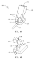
- FIG. 7 and FIG. 8 respectively shows the front view and the rear view of the three-dimensional diagrams of the second embodiment
- FIG. 9 shows the circuit block diagram of the second embodiment.
- a pointing device 100' of the second embodiment includes a fixed base 110, a main body 120 and an outer covering 160, wherein the detailed features and the related connection of the fixed base 110 and main body 120 are approximately similar to the pointing device 100 disclosed in the first embodiment.
- the similar features do not describe again here, and the similar elements use the same reference signs to show for clearing the description.
- FIG. 10 and FIG. 11 respectively shows the front view and a rear view of the three-dimensional diagrams of the combination with an outer covering 160 in the second embodiment.
- the outer covering 160 has an accommodating space 161, further the fixed base 110 and the main body 120 could be disposed to the accommodating space 161 for holding in the outer covering 160.
- the size of the accommodating space 161 is substantially same as the size of the fixed base 110 and the main body 120 at the mouse-operating mode, and the fixed 110 and the main body 120 could be disposed in the forgoing accommodating space 161.
- the outer covering 160 further includes a roller 167 and a first connection port 165.
- the fixed base 110 further has a second connecting port 115, and the second connecting port 115 is electrically connected to the processing unit 123. Therefore, when the fixed base 110 and the main body 120 set in the accommodating space 161 of the outer covering 160, the first connecting port 165 and the second connecting port 115 are couple to each other as the effect as the first connecting port 165 electrically connect to the processing unit 123, wherein the roller 167 electrically connects to the first connecting port 165.
- the roller 167 is selectively triggered to generate a scrolling signal, and the scrolling signal is transferred to the processing unit 123 by the first connecting port 165 and the second connecting port 115.
- the scrolling signal generated from the roller 167 of the outer covering 160 by users can be transferred to the processing unit 123 then transferred to the computer device 200 by the connecting wire 151.
- FIG. 12 shows the cross-section view of A-A' of the second embodiment shown in FIG. 7 .
- the outer covering 160 further includes two pressing portions 163, and the two pressing portions 163 are corresponding to the two buttons 127 of the main body 120 respectively.
- at least one pressing portions 163 is selectively pressed to push the corresponding button 127 that is electrically connected to the processing unit 123, this operating signal can be transferred to the computer device 200 by the processing unit 123.
- the two pressing portions 163 are located corresponding above the two buttons 127 by mechanical manners.
- the pressing portions pushes the corresponding button 127, as the effects as the users press the button 127 directly.
- a person skilled in the art can rely on his/her specific requirements and selectively change amount or structure of the button, and those technologies are not limited in the disclosed embodiment.
- the pointing device 100' disclosed in the second embodiment.
- that assemble the outer covering 160 for adding the holding surface to match the ergonomics so that the users can be used the roller 167 of the outer covering 160 to operate the pointing device 100'.
- the outer covering 160 shows as square shape in the disclosed embodiment, a person skilled in the art can change an arc shape by utilizing various outer shape designs according to ergonomics, his/her experience or design requirements, those technologies are not limited in the disclosed embodiment.
Abstract
Description
- The present invention relates to a pointing device, and more particularly relates to a pointing device that could depend on the different requirements of users to change to a mouse-operating mode or a holding-a-pen-operating mode.
- A pointing device such as a mouse device is commonly used, and the pointing device is an essential input device for the computer system of nowadays. Therefore, almost all users would use the mouse device configured to input instructions and operate the computer system. In order to make the users utilize the mouse device comfortably, so that the manufacturers are improving its functions, appearance and flexibility. For example, the displacement of the cursor which displayed on the computer screen is operated by sensing module of the mouse device that has replaced the trackball of the mouse device in early periods. Furthermore, a roller wheel is disposed between the two buttons of the mouse device, so as to obtain superior convenience while the users using the mouse device.
- However, the use of the mouse device at present that is the user puts its palm placing onto the surface of the mouse device and configured to be hold the whole mouse device, such the above-mentioned using manner that causes the muscles and joints of the users' hand easily tired after a long time. Moreover, the forgoing using manner that also causes the injury with the user's wrist or hand due to the user's wrist lacks the point of application during the long time.
- Nevertheless, the existing mouse device has evolved with ergonomics, or the mouse device is known has evolved with the holding-pen using manner, so as to retard the tiredness of the users' hand. However, the user uses the forgoing mouse device who still maintains the same posture during operation, which causes the problem as injury with the user's wrist and hand yet.
- In view of the forgoing problems, the present invention is directed to a pointing device for solving the problems of the prior art with tiredness of the users' hand, even injury with the user's wrist due to the user who maintains the same posture during use the existing mouse device after the long time.
- The present invention discloses a pointing device which used with a computer device, and the pointing device includes a fixed base and a main body which is selectively rotated to a first angle or a second angle. The fixed base of the pointing device includes a first hinge portion and a sensing displacement module, the first hinge portion is located on one end of the fixed base, and the sensing displacement module is electrically located in the fixed base to generate a displacement signal.
- Further, according to the present invention, the main body of the pointing device includes a second hinge portion and a processing unit, the second hinge portion is located on one end of the main body and pivots on the first hinge portion, and the processing unit is electrically located in the main body and is electrically connected to the sensing displacement module for receiving the displacement signal and transmitting the displacement signal to the computer device.
- The pointing device of the present invention further includes an outer covering, wherein the outer covering has an accommodating space for holding the fixed base and the main body in the outer covering.
- The effectiveness of the present invention is that users can able to pivot the fixed base and main body of the pointing device to a first angle or a second angle depending on the users' requirement, so as to change the operating manner of the pointing device. Therefore, the invention effectively avoid the user who maintains the same posture during a long time, so as to protect the users' hand would not injure, even causing sport injury with the user's wrist.
- The characteristics, realization and functions of the present invention are disclosed in the following description with reference to the preferred exemplified embodiments and the accompanying drawings.
-
-
FIG. 1 is the front view of the three-dimensional diagram of the first embodiment of the present invention. -
FIG. 2 is the rear view of the three-dimensional diagram of the first embodiment of the present invention. -
FIG. 3 is the circuit block diagram of the first embodiment of the present invention. -
FIG. 4A is the front view of the three-dimensional diagram of the holding-a-pen-operating mode of the first embodiment of the present invention. -
FIG. 4B is the enlarged exploded view of the first hinge portion and the second hinge portion of the first embodiment of the present invention. -
FIG. 5 is the lateral view of the holding-a-pen-operating mode of the first embodiment of the present invention. -
FIG. 6 is the lateral view of the mouse-operating mode of the first embodiment of the present invention. -
FIG. 7 is the front view of the three-dimensional diagram of the second embodiment of the present invention. -
FIG. 8 is the rear view of the three-dimensional diagram of the second embodiment of the present invention. -
FIG. 9 is the circuit block diagram of the second embodiment of the present invention. -
FIG. 10 is the front view of the three-dimensional diagram of the combination with an outer covering in the second embodiment of the present invention. -
FIG. 11 is the rear view of the three-dimensional diagram of the combination with the outer covering in the second embodiment of the present invention. -
FIG. 12 is the cross-section view of A-A' of the second embodiment of the present -
FIG. 1 and FIG. 2 respectively shows the front view and the rear view of three-dimensional diagrams of the first embodiment of the present invention, andFIG. 3 shows the circuit block diagram of the first embodiment of the present invention. - In the first embodiment, a
pointing device 100 includes afixed base 110 and amain body 120. In particular, one end of thefixed base 110 has afirst hinge portion 111, and one end of themain body 120 has asecond hinge portion 121. Further, thefixed base 110 and themain body 120 pivot each other by thefirst hinge portion 111 and thesecond hinge portion 121. Asensing displacement module 140 is electrically mounted in thefixed base 110, and thesensing displacement module 140 further includes alight source 143 and a light sensor 145, and additionally, thefixed base 110 has a throughhole 141. Thus, thelight source 143 radiates a sensing light penetrating the throughhole 141, and the light sensor 145 receives the reflective light of the sensing light to generate a displacement signal. However, a person skilled in the art can generate a displacement signal by utilizing various sensing displacement technologies according to his/her experience or design requirements, those technologies are not limited in the disclosed embodiment. - The
main body 120 has aprocessing unit 123, and thesensing displacement module 140 is electrically connected to theprocessing unit 120, such that theprocessing unit 123 receives the displacement signal generated from thesensing displacement module 140. Besides, themain body 120 has twobuttons 127 which are electrically connected to theprocessing unit 123 for input control. However, a person skilled in the art can rely on his/her specific requirements and selectively change amount or structure of the button, and those technologies are not limited in the disclosed embodiment. - The
pointing device 100 of the first embodiment further includes a connectingwire 151, and the connectingwire 151 is electrically connected to thepointing device 100 with acomputer device 200. Therefore, theprocessing unit 123 can transfer the displacement signal to thecomputer device 200 by the connectingwire 151, and users can operate thecomputer device 200 by thepointing device 100 of the first embodiment. However, the communication between thepointing device 100 and thecomputer device 200 can also be conducted by cordless manner, so called wireless, such as Bluetooth, satellite etc. - Another end of the
main body 120 further has ahole 125, and thepointing device 100 of the first embodiment further includes aholding element 130 which could plug into thehole 125, and theholding element 130 could be a pen in the disclosed embodiment. The bore diameter of thehole 125 can be designed substantially same as the rod diameter of the pencil or pen on the market, therefore users could plug a pen, which is carried along by the users into thehole 125. Advantageously, it is convenient for user to hold thepointing device 100. However, theholding element 130 is not limited to a pen, it can be an object which is designed, shaped or manufactured for users to hold. - Subsequently,
FIG. 4A andFIG. 5 respectively shows the front view of the three-dimensional diagram and the lateral view of the holding-a-pen-operating module of the first embodiment.FIG. 4B is the enlarged exploded view to illustrate the connection of thefirst hinge portion 111 and thesecond hinge portion 121 in theFIG. 4A . - Due to the
fixed base 110 andmain body 120 are pivoted by thefirst hinge portion 111 and thesecond hinge portion 121, themain body 120 can rotate from thefixed base 110 and form an angle between themain body 120 and thefixed base 110. In the disclosed embodiment, when thefixed base 110 and themain body 120 rotate to asecond angle 170, so called "holding-a-pen-operating angle", thepointing device 100 is at a holding-a-pen-operating mode, so called "holding-a-pen-operating (HAPO) mode" means users could hold themain body 120 as holding a pen to operate thepointing device 100. - Furthermore, the
first hinge portion 111 includes aprotrusion 119, and thesecond hinge portion 121 includes at least onelocation holes 129, wherein theprotrusion 119 could be inserted into one of thelocation holes 129 for keeping themain body 120 at the second angle (holding-a-pen-operating angle) 170 (as shown inFIG. 4B ). The purpose of setting multiple location holes 129 is to give users different option to chooselocation holes 129 in order to fix themain body 120 and the fixedbase 110 depending on thesecond angle 170. - However, a person skilled in the art can rely on his/her specific requirements and selectively use at least one
protrusion 119 and acorresponding location hole 129. Alternatively, a person skilled in the art can rely on his/her specific requirements and selectively usemultiple protrusions 119 and multiple location holes 129. Even further, a person skilled in the art can rely on his/her specific requirements and selectively use only asingle protrusion 119 and asingle location hole 129. The above-mentioned combinations are used to illustrate the effectiveness of fixing themain body 120 and the fixedbase 110 but the disclosure is not limiting in these. - In the disclosed embodiment, when the fixed
base 110 and themain body 120 are parallel to each other, thepointing device 100 is at a mouse-operating mode. Themain body 120 further has arecess 150, whereby as the size of the fixedbase 110 is smaller than the size of themain body 120, and the fixedbase 110 is embedded in therecess 150, as shown inFIG. 6 which is the lateral view of the mouse-operating mode of the first embodiment. - Therefore, the forgoing
pointing device 100 of the invention make users depending on their requirements to rotate the fixedbase 110 andmain body 120 to the second angle (holding-a-pen-operating angle) 170 (as shown inFIG. 5 ) or the first angle (mouse-operating angle) (as shown inFIG. 6 ) for changing the operating modes of thepointing device 100 according to their requirements. Thus, users don't need to maintain the same posture in a long time to operate thepointing device 100, and effectively avoid tiredness of the users' hand, even avoid ergonomic injury. -
FIG. 7 and FIG. 8 respectively shows the front view and the rear view of the three-dimensional diagrams of the second embodiment, andFIG. 9 shows the circuit block diagram of the second embodiment. - A pointing device 100' of the second embodiment includes a fixed
base 110, amain body 120 and anouter covering 160, wherein the detailed features and the related connection of the fixedbase 110 andmain body 120 are approximately similar to thepointing device 100 disclosed in the first embodiment. Thus, the similar features do not describe again here, and the similar elements use the same reference signs to show for clearing the description. - Subsequently,
FIG. 10 andFIG. 11 respectively shows the front view and a rear view of the three-dimensional diagrams of the combination with anouter covering 160 in the second embodiment. Theouter covering 160 has anaccommodating space 161, further the fixedbase 110 and themain body 120 could be disposed to theaccommodating space 161 for holding in theouter covering 160. In the disclosed embodiment, whereby the size of theaccommodating space 161 is substantially same as the size of the fixedbase 110 and themain body 120 at the mouse-operating mode, and the fixed 110 and themain body 120 could be disposed in the forgoingaccommodating space 161. - The
outer covering 160 further includes aroller 167 and afirst connection port 165. In this disclosed embodiment, and the fixedbase 110 further has a second connectingport 115, and the second connectingport 115 is electrically connected to theprocessing unit 123. Therefore, when the fixedbase 110 and themain body 120 set in theaccommodating space 161 of theouter covering 160, the first connectingport 165 and the second connectingport 115 are couple to each other as the effect as the first connectingport 165 electrically connect to theprocessing unit 123, wherein theroller 167 electrically connects to the first connectingport 165. Thus, theroller 167 is selectively triggered to generate a scrolling signal, and the scrolling signal is transferred to theprocessing unit 123 by the first connectingport 165 and the second connectingport 115. - Therefore, the scrolling signal generated from the
roller 167 of theouter covering 160 by users can be transferred to theprocessing unit 123 then transferred to thecomputer device 200 by the connectingwire 151. -
FIG. 12 shows the cross-section view of A-A' of the second embodiment shown inFIG. 7 . Theouter covering 160 further includes twopressing portions 163, and the twopressing portions 163 are corresponding to the twobuttons 127 of themain body 120 respectively. Thus, at least onepressing portions 163 is selectively pressed to push thecorresponding button 127 that is electrically connected to theprocessing unit 123, this operating signal can be transferred to thecomputer device 200 by theprocessing unit 123. - In this disclosed embodiment, the two
pressing portions 163 are located corresponding above the twobuttons 127 by mechanical manners. When users press one of thepressing portions 163, the pressing portions pushes thecorresponding button 127, as the effects as the users press thebutton 127 directly. A person skilled in the art can rely on his/her specific requirements and selectively change amount or structure of the button, and those technologies are not limited in the disclosed embodiment. - Therefore, users can be used the pointing device 100' disclosed in the second embodiment. At the mouse-operating mode, that assemble the
outer covering 160 for adding the holding surface to match the ergonomics, so that the users can be used theroller 167 of theouter covering 160 to operate the pointing device 100'. Advantageously, it is convenient for user to use the pointing device 100'. It needs to explain that although theouter covering 160 shows as square shape in the disclosed embodiment, a person skilled in the art can change an arc shape by utilizing various outer shape designs according to ergonomics, his/her experience or design requirements, those technologies are not limited in the disclosed embodiment. - The present invention has been disclosed as mentioned-above and it is understood the embodiments are not intended to limit the scope of the present invention. Moreover, as the contents disclosed herein should be readily understood and can be implemented by a person skilled in the art, all equivalent changes or modifications which do not depart from the spirit of the present invention should be encompassed by the appended claims.
Claims (9)
- A pointing device (100, 100'), used with a computer device (200), the pointing device (100, 100') characterized by comprising:a fixed base (110) comprising a first hinge portion (111) and a sensing displacement module (140), the first hinge portion (111) located on one end of the fixed base (110), and the sensing displacement module (140) electrically located in the fixed base (110) to detect displacement and generate a displacement signal; anda main body (120) comprising a second hinge portion (121) and a processing unit (123), the second hinge portion (121) located on one end of the main body (120) and pivoted on the first hinge portion (111), and the processing unit (123) electrically located in the main body (120) and electrically connected to the sensing displacement module (140) for receiving the displacement signal and transmitting the displacement signal to the computer device (200);wherein the main body (120) and the fixed base (110) is selectively rotated to a first angle or a second angle.
- A pointing device (100, 100') as in claim 1, further comprising a holding element (130), and the main body (120) further comprising a hole (125) located on another end of the main body (120), and the holding element (130) plugging into the hole (125).
- A pointing device (100, 100') as in claim 1, wherein the main body (120) further comprises two buttons (127) and the two buttons (127) being electrically connected to the processing unit (123).
- A pointing device (100, 100') as in claim 3, further comprising an outer covering (160), and the outer covering (160) comprising an accommodating space (161) for holding the fixed base (110) and the main body (120) in the outer covering (160).
- A pointing device (100, 100') as in claim 4, wherein the outer covering (160) further comprises two pressing portions (163) corresponding to the two buttons (127) respectively, and at least one of the pressing portions (163) being selectively pressed to push the corresponding button (127).
- A pointing device (100, 100') as in claim 4, wherein the outer covering (160) further comprises a roller (167) and a first connecting port (165), and the fixed base (110) comprises a second connecting port (115) being electrically connected to the processing unit (123); as the fixed base (110) is disposed in the outer covering (160) and the first connecting port (165) and the second connecting port (115) are coupled together, the roller (167) is selectively triggered to generate a scrolling signal, and the scrolling signal is transferred to the processing unit (123) by the first connecting port (165) and the second connecting port (115).
- A pointing device (100, 100') as in claim 1, wherein the sensing displacement module (140) further comprises a light source (143) and a light sensor (145), and the fixed base (110) further comprises a through hole (141); wherein the light source (143) radiates a sensing light penetrating the through hole (141) and the light sensor (145) receives a reflective light of the sensing light to generate the displacement signal.
- A pointing device (100, 100') as in claim 1, wherein the first hinge portion (111) further comprises at least one protrusion (119) and the second hinge portion (121) further comprises at least one location hole (129), and the protrusion (119) is inserted into the location hole (129) for fixing and keeping the main body (120) and the fixed base (110) at the second angle.
- A pointing device (100, 100') as in claim 1, wherein the main body (120) further comprises a recess (150), while the main body (120) is rotated to the first angle, the fixed base (110) is embedded in the recess (150).
Applications Claiming Priority (1)
| Application Number | Priority Date | Filing Date | Title |
|---|---|---|---|
| TW100122729A TWI478011B (en) | 2011-06-29 | 2011-06-29 | Pointing device |
Publications (3)
| Publication Number | Publication Date |
|---|---|
| EP2541374A2 true EP2541374A2 (en) | 2013-01-02 |
| EP2541374A3 EP2541374A3 (en) | 2017-03-08 |
| EP2541374B1 EP2541374B1 (en) | 2020-10-14 |
Family
ID=45655633
Family Applications (1)
| Application Number | Title | Priority Date | Filing Date |
|---|---|---|---|
| EP12155120.4A Active EP2541374B1 (en) | 2011-06-29 | 2012-02-13 | Pointing device |
Country Status (4)
| Country | Link |
|---|---|
| US (1) | US9116556B2 (en) |
| EP (1) | EP2541374B1 (en) |
| JP (1) | JP5514849B2 (en) |
| TW (1) | TWI478011B (en) |
Families Citing this family (4)
| Publication number | Priority date | Publication date | Assignee | Title |
|---|---|---|---|---|
| WO2017127451A1 (en) * | 2016-01-18 | 2017-07-27 | Anoop Molly Joseph | Multipurpose computer mouse |
| TWI606371B (en) * | 2017-03-03 | 2017-11-21 | 致伸科技股份有限公司 | Mouse with joysick mode |
| CN111381692B (en) * | 2018-12-28 | 2023-02-28 | 技嘉科技股份有限公司 | Pen type folding mouse |
| TWI705358B (en) | 2018-12-28 | 2020-09-21 | 技嘉科技股份有限公司 | Pen-shaped folding mouse |
Family Cites Families (26)
| Publication number | Priority date | Publication date | Assignee | Title |
|---|---|---|---|---|
| US4319488A (en) * | 1980-08-01 | 1982-03-16 | Systron-Donner | Accelerometer |
| US4780707A (en) * | 1985-07-18 | 1988-10-25 | Selker Edwin J | Analog input device for a computer |
| JPH04270408A (en) * | 1991-02-26 | 1992-09-25 | Oki Electric Ind Co Ltd | Pointing device |
| US5805143A (en) * | 1996-04-12 | 1998-09-08 | Myers; Paula J. | Stylus mount for a computer mouse |
| JPH10198511A (en) * | 1997-01-14 | 1998-07-31 | Yukiyasu Nishio | Track ball type mouse for computer in which outside shape part is exchangeable |
| JPH10269017A (en) * | 1997-03-26 | 1998-10-09 | Takehisa Higuchi | Pointing device |
| US6031522A (en) | 1997-08-04 | 2000-02-29 | International Business Machines Corporation | Ergonomic computer mouse based on hand size and preference |
| US6714188B1 (en) * | 1999-06-11 | 2004-03-30 | An Ounce Of Invention, Inc | Stick to ergonomically manipulate mouse buttons |
| SE521526C2 (en) | 1999-06-24 | 2003-11-11 | Johan Ullman | Ergonomic pointing device for computer |
| US6784870B2 (en) * | 2001-05-14 | 2004-08-31 | Hewlett-Packard Development Company, L.P. | Portable computer system including detachable peripheral device and combined mouse/joystick for use with same |
| JP5180026B2 (en) | 2002-01-17 | 2013-04-10 | 美恵子 露崎 | Information processing device |
| TWI257567B (en) * | 2003-12-02 | 2006-07-01 | Benq Corp | Folder-type computer mouse |
| TWI228678B (en) * | 2003-12-02 | 2005-03-01 | Benq Corp | Dual mode computer mouse |
| JP2005309685A (en) | 2004-04-20 | 2005-11-04 | Fujitsu Ltd | Attachment for mouse |
| EP1615096B2 (en) * | 2004-07-09 | 2019-10-30 | Gylling Invest AB | Computer input device |
| US7733326B1 (en) * | 2004-08-02 | 2010-06-08 | Prakash Adiseshan | Combination mouse, pen-input and pen-computer device |
| US8648805B2 (en) * | 2004-11-05 | 2014-02-11 | Ftm Computer Products | Fingertip mouse and base |
| JP2007080141A (en) * | 2005-09-16 | 2007-03-29 | Seiko Epson Corp | Keyboard and mouse |
| WO2007114807A1 (en) * | 2006-03-30 | 2007-10-11 | Razer Usa Ltd | Modular computer mouse |
| DE102007049304B4 (en) * | 2007-02-01 | 2020-09-03 | Wera Werkzeuge Gmbh | Wrench with freewheel gear |
| JP4107346B1 (en) | 2007-02-22 | 2008-06-25 | 富士ゼロックス株式会社 | Reading apparatus, writing information processing system, and program |
| US7924266B2 (en) | 2007-04-09 | 2011-04-12 | Microsoft Corporation | Stand alone module mouse with replaceable cover |
| JP4378399B2 (en) * | 2007-07-25 | 2009-12-02 | シャープ株式会社 | Opening / closing door opening / closing control method in drawer-type heating cooker, and drawer-type heating cooker |
| TW201122940A (en) * | 2009-12-22 | 2011-07-01 | Sunplus Innovation Technology Inc | Optical mouse SOC with 8-pins |
| US20120026091A1 (en) * | 2010-08-02 | 2012-02-02 | Brent Harper | Pen-type mouse |
| TWM400614U (en) * | 2010-10-22 | 2011-03-21 | Univ Far East | Mouse device |
-
2011
- 2011-06-29 TW TW100122729A patent/TWI478011B/en not_active IP Right Cessation
-
2012
- 2012-01-13 US US13/350,702 patent/US9116556B2/en not_active Expired - Fee Related
- 2012-02-13 EP EP12155120.4A patent/EP2541374B1/en active Active
- 2012-03-06 JP JP2012048654A patent/JP5514849B2/en not_active Expired - Fee Related
Non-Patent Citations (1)
| Title |
|---|
| None |
Also Published As
| Publication number | Publication date |
|---|---|
| JP2013012174A (en) | 2013-01-17 |
| TW201301089A (en) | 2013-01-01 |
| US20130002547A1 (en) | 2013-01-03 |
| US9116556B2 (en) | 2015-08-25 |
| EP2541374B1 (en) | 2020-10-14 |
| JP5514849B2 (en) | 2014-06-04 |
| TWI478011B (en) | 2015-03-21 |
| EP2541374A3 (en) | 2017-03-08 |
Similar Documents
| Publication | Publication Date | Title |
|---|---|---|
| US10963070B2 (en) | Fingertip mouse and base | |
| US20020171625A1 (en) | Pistol-grip trackball mouse | |
| JP6649503B2 (en) | Wireless positioning pen with pressure-sensitive tip | |
| US9116556B2 (en) | Dual mode mouse device | |
| US10691204B2 (en) | Finger mounted computer input device and method for making the same | |
| JP2010503108A (en) | Finger computer mouse | |
| US20060164392A1 (en) | Integrated mouse and the keyboard device | |
| TWI492104B (en) | Optical mini-mouse | |
| US20110298713A1 (en) | Mouse device with movable button | |
| GB2442973A (en) | Finger worn computer mouse with an optical sensor on a pivoting arm | |
| US20060227101A1 (en) | Hand-held screen-interface device | |
| US10296107B2 (en) | Hand held manipulation apparatus comprising buttons, directional control lever and a flexible conduit | |
| US8599136B2 (en) | Combination mouse and touch input device | |
| US20120026091A1 (en) | Pen-type mouse | |
| CN205563491U (en) | Formula wireless mouse is held to side | |
| KR101625066B1 (en) | Wearable mouse | |
| US20120206346A1 (en) | Finger control device | |
| EP2400376A1 (en) | Combination mouse and touch input device | |
| CN202494989U (en) | Left-and-right hand separate-controlled mouse | |
| JP6593851B1 (en) | pointing device | |
| KR101992993B1 (en) | Wireless mouse | |
| US20190174643A1 (en) | Touch pen and display device using touch pen | |
| KR100960674B1 (en) | Mouse for computer | |
| JP4436244B2 (en) | pointing device | |
| JP2011204183A (en) | Electronic pen |
Legal Events
| Date | Code | Title | Description |
|---|---|---|---|
| PUAI | Public reference made under article 153(3) epc to a published international application that has entered the european phase |
Free format text: ORIGINAL CODE: 0009012 |
|
| AK | Designated contracting states |
Kind code of ref document: A2 Designated state(s): AL AT BE BG CH CY CZ DE DK EE ES FI FR GB GR HR HU IE IS IT LI LT LU LV MC MK MT NL NO PL PT RO RS SE SI SK SM TR |
|
| AX | Request for extension of the european patent |
Extension state: BA ME |
|
| RAP1 | Party data changed (applicant data changed or rights of an application transferred) |
Owner name: GIGA-BYTE TECHNOLOGY CO., LTD. |
|
| PUAL | Search report despatched |
Free format text: ORIGINAL CODE: 0009013 |
|
| AK | Designated contracting states |
Kind code of ref document: A3 Designated state(s): AL AT BE BG CH CY CZ DE DK EE ES FI FR GB GR HR HU IE IS IT LI LT LU LV MC MK MT NL NO PL PT RO RS SE SI SK SM TR |
|
| AX | Request for extension of the european patent |
Extension state: BA ME |
|
| RIC1 | Information provided on ipc code assigned before grant |
Ipc: G06F 3/033 20130101AFI20170130BHEP |
|
| STAA | Information on the status of an ep patent application or granted ep patent |
Free format text: STATUS: REQUEST FOR EXAMINATION WAS MADE |
|
| 17P | Request for examination filed |
Effective date: 20170616 |
|
| RBV | Designated contracting states (corrected) |
Designated state(s): AL AT BE BG CH CY CZ DE DK EE ES FI FR GB GR HR HU IE IS IT LI LT LU LV MC MK MT NL NO PL PT RO RS SE SI SK SM TR |
|
| STAA | Information on the status of an ep patent application or granted ep patent |
Free format text: STATUS: EXAMINATION IS IN PROGRESS |
|
| 17Q | First examination report despatched |
Effective date: 20171130 |
|
| GRAP | Despatch of communication of intention to grant a patent |
Free format text: ORIGINAL CODE: EPIDOSNIGR1 |
|
| STAA | Information on the status of an ep patent application or granted ep patent |
Free format text: STATUS: GRANT OF PATENT IS INTENDED |
|
| INTG | Intention to grant announced |
Effective date: 20200508 |
|
| GRAS | Grant fee paid |
Free format text: ORIGINAL CODE: EPIDOSNIGR3 |
|
| GRAA | (expected) grant |
Free format text: ORIGINAL CODE: 0009210 |
|
| STAA | Information on the status of an ep patent application or granted ep patent |
Free format text: STATUS: THE PATENT HAS BEEN GRANTED |
|
| AK | Designated contracting states |
Kind code of ref document: B1 Designated state(s): AL AT BE BG CH CY CZ DE DK EE ES FI FR GB GR HR HU IE IS IT LI LT LU LV MC MK MT NL NO PL PT RO RS SE SI SK SM TR |
|
| REG | Reference to a national code |
Ref country code: GB Ref legal event code: FG4D |
|
| REG | Reference to a national code |
Ref country code: AT Ref legal event code: REF Ref document number: 1324216 Country of ref document: AT Kind code of ref document: T Effective date: 20201015 Ref country code: CH Ref legal event code: EP |
|
| REG | Reference to a national code |
Ref country code: DE Ref legal event code: R096 Ref document number: 602012072762 Country of ref document: DE |
|
| REG | Reference to a national code |
Ref country code: IE Ref legal event code: FG4D |
|
| REG | Reference to a national code |
Ref country code: AT Ref legal event code: MK05 Ref document number: 1324216 Country of ref document: AT Kind code of ref document: T Effective date: 20201014 |
|
| REG | Reference to a national code |
Ref country code: NL Ref legal event code: MP Effective date: 20201014 |
|
| PG25 | Lapsed in a contracting state [announced via postgrant information from national office to epo] |
Ref country code: RS Free format text: LAPSE BECAUSE OF FAILURE TO SUBMIT A TRANSLATION OF THE DESCRIPTION OR TO PAY THE FEE WITHIN THE PRESCRIBED TIME-LIMIT Effective date: 20201014 Ref country code: FI Free format text: LAPSE BECAUSE OF FAILURE TO SUBMIT A TRANSLATION OF THE DESCRIPTION OR TO PAY THE FEE WITHIN THE PRESCRIBED TIME-LIMIT Effective date: 20201014 Ref country code: NO Free format text: LAPSE BECAUSE OF FAILURE TO SUBMIT A TRANSLATION OF THE DESCRIPTION OR TO PAY THE FEE WITHIN THE PRESCRIBED TIME-LIMIT Effective date: 20210114 Ref country code: PT Free format text: LAPSE BECAUSE OF FAILURE TO SUBMIT A TRANSLATION OF THE DESCRIPTION OR TO PAY THE FEE WITHIN THE PRESCRIBED TIME-LIMIT Effective date: 20210215 Ref country code: NL Free format text: LAPSE BECAUSE OF FAILURE TO SUBMIT A TRANSLATION OF THE DESCRIPTION OR TO PAY THE FEE WITHIN THE PRESCRIBED TIME-LIMIT Effective date: 20201014 Ref country code: GR Free format text: LAPSE BECAUSE OF FAILURE TO SUBMIT A TRANSLATION OF THE DESCRIPTION OR TO PAY THE FEE WITHIN THE PRESCRIBED TIME-LIMIT Effective date: 20210115 |
|
| REG | Reference to a national code |
Ref country code: LT Ref legal event code: MG4D |
|
| PG25 | Lapsed in a contracting state [announced via postgrant information from national office to epo] |
Ref country code: IS Free format text: LAPSE BECAUSE OF FAILURE TO SUBMIT A TRANSLATION OF THE DESCRIPTION OR TO PAY THE FEE WITHIN THE PRESCRIBED TIME-LIMIT Effective date: 20210214 Ref country code: ES Free format text: LAPSE BECAUSE OF FAILURE TO SUBMIT A TRANSLATION OF THE DESCRIPTION OR TO PAY THE FEE WITHIN THE PRESCRIBED TIME-LIMIT Effective date: 20201014 Ref country code: BG Free format text: LAPSE BECAUSE OF FAILURE TO SUBMIT A TRANSLATION OF THE DESCRIPTION OR TO PAY THE FEE WITHIN THE PRESCRIBED TIME-LIMIT Effective date: 20210114 Ref country code: AT Free format text: LAPSE BECAUSE OF FAILURE TO SUBMIT A TRANSLATION OF THE DESCRIPTION OR TO PAY THE FEE WITHIN THE PRESCRIBED TIME-LIMIT Effective date: 20201014 Ref country code: SE Free format text: LAPSE BECAUSE OF FAILURE TO SUBMIT A TRANSLATION OF THE DESCRIPTION OR TO PAY THE FEE WITHIN THE PRESCRIBED TIME-LIMIT Effective date: 20201014 Ref country code: PL Free format text: LAPSE BECAUSE OF FAILURE TO SUBMIT A TRANSLATION OF THE DESCRIPTION OR TO PAY THE FEE WITHIN THE PRESCRIBED TIME-LIMIT Effective date: 20201014 Ref country code: LV Free format text: LAPSE BECAUSE OF FAILURE TO SUBMIT A TRANSLATION OF THE DESCRIPTION OR TO PAY THE FEE WITHIN THE PRESCRIBED TIME-LIMIT Effective date: 20201014 |
|
| PG25 | Lapsed in a contracting state [announced via postgrant information from national office to epo] |
Ref country code: HR Free format text: LAPSE BECAUSE OF FAILURE TO SUBMIT A TRANSLATION OF THE DESCRIPTION OR TO PAY THE FEE WITHIN THE PRESCRIBED TIME-LIMIT Effective date: 20201014 |
|
| REG | Reference to a national code |
Ref country code: DE Ref legal event code: R097 Ref document number: 602012072762 Country of ref document: DE |
|
| PG25 | Lapsed in a contracting state [announced via postgrant information from national office to epo] |
Ref country code: LT Free format text: LAPSE BECAUSE OF FAILURE TO SUBMIT A TRANSLATION OF THE DESCRIPTION OR TO PAY THE FEE WITHIN THE PRESCRIBED TIME-LIMIT Effective date: 20201014 Ref country code: RO Free format text: LAPSE BECAUSE OF FAILURE TO SUBMIT A TRANSLATION OF THE DESCRIPTION OR TO PAY THE FEE WITHIN THE PRESCRIBED TIME-LIMIT Effective date: 20201014 Ref country code: SK Free format text: LAPSE BECAUSE OF FAILURE TO SUBMIT A TRANSLATION OF THE DESCRIPTION OR TO PAY THE FEE WITHIN THE PRESCRIBED TIME-LIMIT Effective date: 20201014 Ref country code: EE Free format text: LAPSE BECAUSE OF FAILURE TO SUBMIT A TRANSLATION OF THE DESCRIPTION OR TO PAY THE FEE WITHIN THE PRESCRIBED TIME-LIMIT Effective date: 20201014 Ref country code: CZ Free format text: LAPSE BECAUSE OF FAILURE TO SUBMIT A TRANSLATION OF THE DESCRIPTION OR TO PAY THE FEE WITHIN THE PRESCRIBED TIME-LIMIT Effective date: 20201014 Ref country code: SM Free format text: LAPSE BECAUSE OF FAILURE TO SUBMIT A TRANSLATION OF THE DESCRIPTION OR TO PAY THE FEE WITHIN THE PRESCRIBED TIME-LIMIT Effective date: 20201014 |
|
| PLBE | No opposition filed within time limit |
Free format text: ORIGINAL CODE: 0009261 |
|
| STAA | Information on the status of an ep patent application or granted ep patent |
Free format text: STATUS: NO OPPOSITION FILED WITHIN TIME LIMIT |
|
| PG25 | Lapsed in a contracting state [announced via postgrant information from national office to epo] |
Ref country code: DK Free format text: LAPSE BECAUSE OF FAILURE TO SUBMIT A TRANSLATION OF THE DESCRIPTION OR TO PAY THE FEE WITHIN THE PRESCRIBED TIME-LIMIT Effective date: 20201014 |
|
| 26N | No opposition filed |
Effective date: 20210715 |
|
| PG25 | Lapsed in a contracting state [announced via postgrant information from national office to epo] |
Ref country code: MC Free format text: LAPSE BECAUSE OF FAILURE TO SUBMIT A TRANSLATION OF THE DESCRIPTION OR TO PAY THE FEE WITHIN THE PRESCRIBED TIME-LIMIT Effective date: 20201014 |
|
| REG | Reference to a national code |
Ref country code: BE Ref legal event code: MM Effective date: 20210228 |
|
| PG25 | Lapsed in a contracting state [announced via postgrant information from national office to epo] |
Ref country code: CH Free format text: LAPSE BECAUSE OF NON-PAYMENT OF DUE FEES Effective date: 20210228 Ref country code: AL Free format text: LAPSE BECAUSE OF FAILURE TO SUBMIT A TRANSLATION OF THE DESCRIPTION OR TO PAY THE FEE WITHIN THE PRESCRIBED TIME-LIMIT Effective date: 20201014 Ref country code: IT Free format text: LAPSE BECAUSE OF FAILURE TO SUBMIT A TRANSLATION OF THE DESCRIPTION OR TO PAY THE FEE WITHIN THE PRESCRIBED TIME-LIMIT Effective date: 20201014 Ref country code: LU Free format text: LAPSE BECAUSE OF NON-PAYMENT OF DUE FEES Effective date: 20210213 Ref country code: LI Free format text: LAPSE BECAUSE OF NON-PAYMENT OF DUE FEES Effective date: 20210228 |
|
| PG25 | Lapsed in a contracting state [announced via postgrant information from national office to epo] |
Ref country code: SI Free format text: LAPSE BECAUSE OF FAILURE TO SUBMIT A TRANSLATION OF THE DESCRIPTION OR TO PAY THE FEE WITHIN THE PRESCRIBED TIME-LIMIT Effective date: 20201014 |
|
| PG25 | Lapsed in a contracting state [announced via postgrant information from national office to epo] |
Ref country code: IE Free format text: LAPSE BECAUSE OF NON-PAYMENT OF DUE FEES Effective date: 20210213 Ref country code: FR Free format text: LAPSE BECAUSE OF NON-PAYMENT OF DUE FEES Effective date: 20210228 |
|
| PGFP | Annual fee paid to national office [announced via postgrant information from national office to epo] |
Ref country code: GB Payment date: 20211223 Year of fee payment: 11 |
|
| PGFP | Annual fee paid to national office [announced via postgrant information from national office to epo] |
Ref country code: DE Payment date: 20211222 Year of fee payment: 11 |
|
| PG25 | Lapsed in a contracting state [announced via postgrant information from national office to epo] |
Ref country code: IS Free format text: LAPSE BECAUSE OF FAILURE TO SUBMIT A TRANSLATION OF THE DESCRIPTION OR TO PAY THE FEE WITHIN THE PRESCRIBED TIME-LIMIT Effective date: 20210214 |
|
| PG25 | Lapsed in a contracting state [announced via postgrant information from national office to epo] |
Ref country code: BE Free format text: LAPSE BECAUSE OF NON-PAYMENT OF DUE FEES Effective date: 20210228 |
|
| PG25 | Lapsed in a contracting state [announced via postgrant information from national office to epo] |
Ref country code: HU Free format text: LAPSE BECAUSE OF FAILURE TO SUBMIT A TRANSLATION OF THE DESCRIPTION OR TO PAY THE FEE WITHIN THE PRESCRIBED TIME-LIMIT; INVALID AB INITIO Effective date: 20120213 Ref country code: CY Free format text: LAPSE BECAUSE OF FAILURE TO SUBMIT A TRANSLATION OF THE DESCRIPTION OR TO PAY THE FEE WITHIN THE PRESCRIBED TIME-LIMIT Effective date: 20201014 |
|
| REG | Reference to a national code |
Ref country code: DE Ref legal event code: R119 Ref document number: 602012072762 Country of ref document: DE |
|
| GBPC | Gb: european patent ceased through non-payment of renewal fee |
Effective date: 20230213 |
|
| PG25 | Lapsed in a contracting state [announced via postgrant information from national office to epo] |
Ref country code: GB Free format text: LAPSE BECAUSE OF NON-PAYMENT OF DUE FEES Effective date: 20230213 |
|
| PG25 | Lapsed in a contracting state [announced via postgrant information from national office to epo] |
Ref country code: GB Free format text: LAPSE BECAUSE OF NON-PAYMENT OF DUE FEES Effective date: 20230213 Ref country code: DE Free format text: LAPSE BECAUSE OF NON-PAYMENT OF DUE FEES Effective date: 20230901 |